EP4349656A1 - Dachschienenanordnung zur positionierung auf einem fahrzeugdach - Google Patents
Dachschienenanordnung zur positionierung auf einem fahrzeugdach Download PDFInfo
- Publication number
- EP4349656A1 EP4349656A1 EP23200230.3A EP23200230A EP4349656A1 EP 4349656 A1 EP4349656 A1 EP 4349656A1 EP 23200230 A EP23200230 A EP 23200230A EP 4349656 A1 EP4349656 A1 EP 4349656A1
- Authority
- EP
- European Patent Office
- Prior art keywords
- bar
- feet
- fixing
- pair
- roof
- Prior art date
- Legal status (The legal status is an assumption and is not a legal conclusion. Google has not performed a legal analysis and makes no representation as to the accuracy of the status listed.)
- Granted
Links
Images


Classifications
-
- B—PERFORMING OPERATIONS; TRANSPORTING
- B60—VEHICLES IN GENERAL
- B60R—VEHICLES, VEHICLE FITTINGS, OR VEHICLE PARTS, NOT OTHERWISE PROVIDED FOR
- B60R9/00—Supplementary fittings on vehicle exterior for carrying loads, e.g. luggage, sports gear or the like
- B60R9/04—Carriers associated with vehicle roof
- B60R9/045—Carriers being adjustable or transformable, e.g. expansible, collapsible
Definitions
- the present invention relates to a set of roof bars intended to be positioned on the roof of a vehicle.
- roof bars to support, for example, a roof box or a bicycle rack on the roof of a vehicle.
- transverse roof bars are hung on longitudinal bars attached to the vehicle.
- the fixing of the transverse roof bars to the longitudinal bars is often carried out by means of a screw-nut assembly passing through the transverse roof bar and the longitudinal bar.
- adjustable jaws positioned at each end of the transverse roof bar and configured to each clamp a longitudinal bar.
- the roof bars are close to the roof.
- the roof bars are further away from the roof (in a direction normal to the plane of the roof) to allow the passage of an accessory attachment system.
- a solution known from the document US2016243994 consists of using foldable roof bars which can be fixed on support rails secured to the roof in two specific positions, a non-operating position, in which each roof bar is fixed on one of the support rails at the level of a first pair of fixing points, and an operating position, in which each roof bar is fixed on each of the support rails at a second pair of fixing points.
- the roof bars are attached to the support rails using mounting elements that can be removed without tools.
- This solution requires that the roof bars be successively dismantled and reassembled on the support rails so as to move from the non-operating position to the operating position and vice versa.
- the present invention aims to provide a roof bar assembly which limits assembly time while reducing manufacturing costs.
- the roof bar assembly of the invention will reduce manufacturing costs due to the use of a single fixing point on one of the feet of fixing to achieve the fixing of both the second bar in its longitudinal position and the first bar in its transverse position.
- the term “longitudinal” refers to a direction parallel to the direction of the length of the vehicle and the term “transverse” refers to a direction parallel to the direction of the width of the vehicle.
- the terms “front”, “rear” and “lateral” are used in relation to the direction of travel of the vehicle.
- the term “horizontal” refers to a direction or surface parallel to the ground when the vehicle wheels are in contact with the ground and the term “vertical” refers to a direction or surface perpendicular to the ground when the vehicle wheels are in contact with the ground. in contact with the ground.
- the terms “lower” and “upper”, or “bottom” and “top” refer to relative positions in the vertical direction.
- the terms “inward facing” and “outward facing” refer to orientations respectively directed towards the center of the vehicle and away from the center of the vehicle.
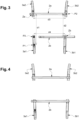
- a set 1 of roof bars according to a first alternative embodiment of the invention, the roof bars being in a longitudinal position.
- the set 1 of roof bars comprises in particular two pairs of fixing feet intended to be fixed on each side of a vehicle roof, respectively a first pair of fixing feet 3a1, 3a2 intended to be fixed on the left side of the roof, and a second pair of fixing feet 3b1, 3b2 intended to be fixed on the right side of the vehicle.
- Each pair of fixing feet comprises a rear fixing foot, respectively the fixing feet 3a1 and 3b1, arranged at the rear relative to the direction of travel of the vehicle and a front fixing foot, respectively the fixing feet 3a2 and 3b2, arranged at the front relative to the direction of travel of the vehicle.
- the front and rear fixing feet of each of the pairs are aligned in a direction parallel to a longitudinal axis X defined by the vehicle,
- the set 1 of roof bars further comprises a pair of roof bars extending respectively between the rear and front fixing feet of one of the pairs of fixing feet, respectively a first roof bar 2a extending between the rear fixing foot 3a1 and the front fixing foot 3a2 and a second roof bar 2b extending between the rear fixing foot 3b1 and the front fixing foot 3b2.
- Each roof bar 2a, 2b is connected to one of the fixing feet of one of the pairs of fixing feet by means of an articulation so as to be able to be positioned in at least two specific use positions, respectively a longitudinal position, represented in particular on the figure 2 , in which it is parallel to the longitudinal axis X, and a transverse position, represented in particular on the figure 4 , in which it is oriented perpendicular to said longitudinal axis X.
- the roof bars 2a, 2b first pivot around a pivot axis to position themselves at right angles to their longitudinal position, as shown in the figure.
- Figure 3 In the configuration shown on the Figure 3 , the pivot axis Za of the first roof bar 2a is positioned at the level of the front fixing foot 3a2 and the pivot axis Zb of the second roof bar 2b is positioned at the level of the rear fixing foot 3b1. It should be noted that the relative position of the pivot axes Za and Zb does not allow the roof bars 2a, 2b to reach specific fixing points, referenced P2 and P3 on the Figure 3 , positioned respectively on the front fixing foot 3b2 and on the rear fixing foot 3a1.
- These fixing points P2 and P3 respectively correspond to the positions in which locking means integrated in the first roof bar 2a, respectively in the second roof bar 2b, can cooperate with complementary locking means integrated in the front fixing foot 3b2, respectively in the rear fixing foot 3a1, so as to ensure removable fixing of said roof bars 2a, 2b on said fixing feet 3b2, 3a1 when they are in their transverse position.
- the first roof bar 2a is configured such that the pivot axis Za of the first roof bar roof 2a is distant by a distance d1 from a fixing point P1 positioned on the rear fixing foot 3a1, said fixing point P1 corresponding to the position in which the locking means integrated in the first roof bar 2a can cooperate with complementary locking means integrated into the rear fixing foot 3a1 so as to ensure removable fixing of the first roof bar 2a on said rear fixing foot 3a1 when it is in its longitudinal position.
- this distance d1 is less than the distance d3 separating the pivot axis Za from the attachment point P2.
- the second roof bar 2b is configured such that the pivot axis Zb of the second roof bar 2b is distant by a distance d2 from the fixing point P2 positioned on the front fixing foot 3b2, said fixing point P2 corresponding to the position in which the locking means integrated in the second roof bar 2b can cooperate with complementary locking means integrated in the front fixing foot 3b2 so as to ensure removable fixing of the second roof bar roof 2b on said front fixing foot 3b2 when it is in its longitudinal position.
- this distance d2 is less than the distance d4 separating the pivot axis Zb from the attachment point P3.
- the set 1 of roof bars thus configured has the advantage of using the same fixing point, namely the fixing point P2, to fix the first roof bar 2a in its transverse position and the fixing of the second roof bar 2b in its longitudinal position.
- This configuration therefore makes it possible to limit the number of fixing points compared to the sets of roof bars of the prior art which require the presence of four fixing points.
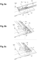
- a specific solution making it possible to achieve this movement of both rotation and translation of the first roof bar 2a is shown on the figures 5a to 5c , as well as on the figure 7a .
- This solution is also used to carry out the rotation and translation movement of the second roof bar 2b.
- the roof bar 2a as shown on the figures 5a to 5c , has had its upper part amputated so as to see the joint around which it pivots.
- This solution consists of providing a lower wall 21 of the roof bar 2a with a slot 4 along which the joint 5 can slide around which the roof bar 2a can pivot relative to the front fixing foot 3a2.
- the slot 4 is rectilinear and oriented parallel to the longitudinal axis X when the roof bar 2a is in its longitudinal position.
- the joint 5 comprises a T-shaped screw 50 provided with a head 51 of rectangular shape.
- the head 51 is arranged above the lower wall 21, being oriented perpendicular to the slot 4.
- the width of the head 51 being greater than the width of the slot 4, the roof bar 2a abuts against the head 51 when it rises.
- the screw 50 is also provided with a threaded rod 52 received partially in the slot 4 and in a bore 32 formed through an upper wall 31 of the front fixing foot 3a2 which faces the lower wall 21 of the roof bar 2a, a nut 53 being screwed to the free end of the threaded rod 52, the nut 53 pressing against a spring washer 54 disposed between said nut 53 and said upper wall 31, thus pressing the head 51 against the lower wall 21 .
- the articulation 5 also comprises a guide element 55 disposed between the roof bar 2a and the front fixing foot 3a2.
- This guide element 55 is provided with a central cavity 56 at least partially housing the screw 50.
- the guide element 55 also comprises two lugs 57 arranged on either side of the head 51 of the screw 50, said lugs 57 being dimensioned to slide without play inside the slot 4.
- the articulation 5 ensures the movement of the roof bar 2a from its longitudinal position, shown on the figure 5a , at the intermediate position, shown on the figure 5b , by a counterclockwise rotation of 90° of the roof bar 2a around the axis Za defined by the T screw 50.
- the lugs 57 of the guide element 55 also pivoted, while retaining their relative position along the slot 4. In this position, they are contiguous to one of the ends of the slot 4.
- the movement of the first roof bar 2a with respect to the front fixing foot 3a2, as described above, can be carried out in a similar manner for the second roof bar 2b with respect to the foot of rear attachment 3b1.
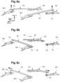
- the roof bars 2a, 2b can advantageously perform a ball joint movement around their articulation so as to position them in a series of intermediate positions in which they will be correctly arranged relative to each other to allow their movement in rotation around their respective pivot axis Za and Zb. Indeed, without this ball joint movement, the roof bars 2a, 2b would be aligned in the same plane and, therefore, would abut against each other during their rotational movement.
- a first intermediate position, represented on the figure 6a is reached when, from the position shown on the figure 1 , the rear end of the first roof bar 2a is raised to move it away in a vertical direction Z from the rear fixing foot 3a1 and the front end of the second roof bar 2b is raised to move it away in a direction vertical Z of the front fixing foot 3b2.
- a second intermediate position, shown on the figure 6b is reached when, from the position shown on the figure 6a , the first roof bar 2a is pivoted around the pivot axis Za so as to orient its rear end towards the front fixing foot 3b2 and the second roof bar 2b is pivoted around the pivot axis Zb so to orient its front end towards the rear fixing foot 3a1.
- a third intermediate position, represented on the figure 6c is reached when, from the position shown on the figure 6b , the first roof bar 2a is translated along a transverse direction Y so as to position its rear end above the front fixing foot 3b2 and the second roof bar 2b is translated along the transverse direction Y of so as to position its front end above the rear fixing foot 3a1.
- a final position, shown on the figure 6d is reached when, from the position shown on the figure 6c , the rear end of the first roof bar 2a is lowered to bring it into contact with the front fixing foot 3b2 and the front end of the second roof bar 2b is lowered to bring it into contact with the fixing foot rear 3a1.
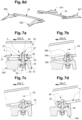
- the internal wall 58 of the guide element 55 which surrounds the central cavity 56 in which the screw 50 is housed has on a high portion 58b, which is located above a central circular zone 58a, a flared conical shape upwards and on a lower portion 58c, which is located below said middle zone 58a, a conical shape flared downwards.
- the internal wall 58 of the guide element 55 forms a cam pattern against which the screw 50 rests during the movement of the first roof bar 2a, respectively of the second roof bar 2b, from its longitudinal position to its transverse position and vice versa, thus allowing the ball joint movement of said roof bars 2a, 2b.
- the guide element 55 pivots relative to the screw 50 around an axis perpendicular to the longitudinal axis X until the guide element 55 abuts against the screw 50 at the level of its internal wall 58c.
- the guide element 55 and the screw 50 pivot together relative to the front fixing foot 3a2 around the pivot axis Za, the guide element 55 being in contact with the screw 50 at the level of the internal face of the lugs 57.
- the figure 7c shows the front fixing foot 3a2 in cross section. This figure shows that the front fixing foot 3a2 is provided with a projecting shape 33 projecting from its upper wall 31. The function of this projecting shape 33 will be specified in the paragraphs which follow.
- the roof bar 2a When moving the roof bar 2a from its second intermediate position, shown on the figure 7c , in its third intermediate position, shown on the figure 7d , the roof bar 2a is translated relative to the front fixing foot 3a2 along the transverse direction Y until the lug 57 which is the most external abuts against the external end of the slot 4, l the guide element 55 always being in contact with the screw 50 at its internal wall 58c.
- the translational movements of the roof bars 2a, 2b can be carried out thanks to a play in the holding mechanism which will be described later with the spring washer 54.
- This spring washer will be put in compression to ensure good fixing of these bars roof 2a, 2b in their transverse position.
- This additional projecting shape 33 could for example be perpendicular to the longitudinal axis X and be located near the joint 5.
- the joint 5 differs from that shown on the figures 7a to 7f by the fact that instead of providing a projecting shape 33 to define the locked state of the joint, the solution consists of arranging the screw 50 eccentrically relative to an axis X' parallel to the longitudinal axis and with respect to an axis Y' perpendicular to the longitudinal axis transversal.
- the lower face 59 of the guide element 55 may have a hemispherical shape intended to cooperate with a corresponding recessed shape of the upper wall 31 of the front fixing foot 3a2 so as to allow the pivoting movement of the guide element 55 around the axis X' or Y'.
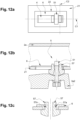
- the joint 5 differs from that shown on the figures 8a and 8b by the fact that instead of providing an eccentric position of the screw 50 to define the locked state of the joint, the solution consists of providing the guide element 55 with two lower lugs 62 projecting under the lower face 59 of the guide element 55, as shown in the figures 9a and 9b , and to provide the upper wall 31 of the front fixing foot 3a2 with a cam path of annular shape along which the lower lugs 62 move during rotational movements of the roof bar 2a. As shown on the figure 9c , the cam path comprises two projecting shapes 35 separated by two hollow shapes 34.
- a zone 22 of the lower wall 21 of the first roof bar 2a, respectively of the second roof bar 2b, which surrounds the slot 4 is covered with a covering part 6 formed of a material with low coefficient of friction, such as polyoxymethylene or polyamide 6.
- This covering part 6 will in particular limit the friction of the head 51 of the screw 50 against the lower face 21 of the first roof bar 2a, respectively of the second roof bar 2b, when sliding the joint 5 along the slot 4.
- the covering part 6 can advantageously be received inside grooves 57a formed along the external periphery of the lugs 57 of the guide element 55.
- the roof bar 2a comprises a threaded male member 7, such as a screw
- the front fixing foot 3b2 comprises a threaded female member 8, such as a nut, intended to cooperate with said threaded male member 7 so as to ensure the fixing of the roof bar 2a on said front fixing foot 3b2.
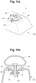
- roof bars 2a and 2b can advantageously be equipped with removable covers 23 as shown in the Figure 13 .
- the locking means integrated in each of the roof bars 2a, 2b comprise a retaining yoke 11 and an asymmetrical core 12 linked in rotation in the retaining yoke 11, and the complementary locking means of the fixing feet 3a1 and 3b2, on which said roof bars 2a, 2b are fixed, comprise a quadrangular opening 13 formed in the upper wall 31 of each of the fixing feet 3a1 and 3b2.
- the retaining yoke 11 and the core 12 are configured such that, upon rotation of the core 12, the retaining yoke 11 passes from a retracted position, in which it is removable from the quadrangular opening 13, to a expanded position, in which it is locked in the quadrangular opening 13.
- This solution has been described in particular in the patent EP 3 124 328 B1 .
- the rear and front fixing feet 3a1 and 3a2 of the first pair of fixing feet may be integrated into the same part so as to form a single support rail.
Landscapes
- Engineering & Computer Science (AREA)
- Mechanical Engineering (AREA)
- Fittings On The Vehicle Exterior For Carrying Loads, And Devices For Holding Or Mounting Articles (AREA)
- Body Structure For Vehicles (AREA)
Applications Claiming Priority (1)
| Application Number | Priority Date | Filing Date | Title |
|---|---|---|---|
| FR2210242A FR3140594A1 (fr) | 2022-10-06 | 2022-10-06 | Ensemble de barres de toit destiné à être positionné sur le toit d’un véhicule |
Publications (2)
| Publication Number | Publication Date |
|---|---|
| EP4349656A1 true EP4349656A1 (de) | 2024-04-10 |
| EP4349656B1 EP4349656B1 (de) | 2025-09-03 |
Family
ID=84820373
Family Applications (1)
| Application Number | Title | Priority Date | Filing Date |
|---|---|---|---|
| EP23200230.3A Active EP4349656B1 (de) | 2022-10-06 | 2023-09-27 | Dachschienenanordnung zur positionierung auf einem fahrzeugdach |
Country Status (2)
| Country | Link |
|---|---|
| EP (1) | EP4349656B1 (de) |
| FR (1) | FR3140594A1 (de) |
Citations (3)
| Publication number | Priority date | Publication date | Assignee | Title |
|---|---|---|---|---|
| US5377890A (en) * | 1993-04-24 | 1995-01-03 | Gebr. Happich Gmbh | Roof rack for vehicles |
| US20160243994A1 (en) | 2015-02-23 | 2016-08-25 | Jac Products, Inc. | System and method for vehicle article carrier having stowable cross bars |
| EP3124328A1 (de) * | 2015-07-29 | 2017-02-01 | MECAPLAST France | Dachlastenträger |
Family Cites Families (2)
| Publication number | Priority date | Publication date | Assignee | Title |
|---|---|---|---|---|
| FR2980423B1 (fr) * | 2011-09-27 | 2013-09-06 | Renault Sa | Dispositif de fixation d'une barre de toit d'un vehicule automobile et agencement de barres de toit assemblees via un tel dispositif suivant plusieurs configurations |
| US10576901B2 (en) * | 2017-01-17 | 2020-03-03 | Jac Products, Inc. | Vehicle article carrier having swing-in-place and stowable cross bars |
-
2022
- 2022-10-06 FR FR2210242A patent/FR3140594A1/fr active Pending
-
2023
- 2023-09-27 EP EP23200230.3A patent/EP4349656B1/de active Active
Patent Citations (4)
| Publication number | Priority date | Publication date | Assignee | Title |
|---|---|---|---|---|
| US5377890A (en) * | 1993-04-24 | 1995-01-03 | Gebr. Happich Gmbh | Roof rack for vehicles |
| US20160243994A1 (en) | 2015-02-23 | 2016-08-25 | Jac Products, Inc. | System and method for vehicle article carrier having stowable cross bars |
| EP3124328A1 (de) * | 2015-07-29 | 2017-02-01 | MECAPLAST France | Dachlastenträger |
| EP3124328B1 (de) | 2015-07-29 | 2019-08-21 | Novares France | Dachlastenträger |
Also Published As
| Publication number | Publication date |
|---|---|
| FR3140594A1 (fr) | 2024-04-12 |
| EP4349656B1 (de) | 2025-09-03 |
Similar Documents
| Publication | Publication Date | Title |
|---|---|---|
| EP3333643B1 (de) | Befestigungsvorrichtung | |
| EP2532271B1 (de) | Tisch mit mindestens einem umdrehbaren Bein | |
| EP1708911A1 (de) | Verbinder zur verbindung eines arms in form eines segments eines profilierten elements mit einer angelenkten struktur eines windschutzscheibenwischerblatts | |
| FR2609411A1 (fr) | Vehicule-jouet a essieu basculant | |
| EP3222476B1 (de) | Adapter zur verbindung mit dem freie ende eines wischarms und anordnung mit einem adapter und einem wischarm | |
| WO2004103652A2 (fr) | Organe prehenseur pour la retenue d’une piece a deplacer par un manipulateur, agence en structure etagee comprenant une poutre sur laquelle sont articules des bras porteurs d’une tete de retenue | |
| EP4349656B1 (de) | Dachschienenanordnung zur positionierung auf einem fahrzeugdach | |
| EP1946991B1 (de) | Zusammenklappbares Fahrgestell für Kinderwagen | |
| EP3170049A1 (de) | Scharnier für brillengestell | |
| EP3251904B1 (de) | Anschlussadapter des freien endabschnitts eines scheibenwischerarms, und anordnung, die einen solchen adapter und einen scheibenwischerarm umfasst | |
| FR3103750A1 (fr) | Dossier de siege de vehicule, siege de vehicule comportant un tel dossier et procede de fabrication d’un tel dossier de siege | |
| EP4425278A1 (de) | Uhrwerkbank und vorderarmstütze für eine uhrwerkbank | |
| EP0451643A2 (de) | Kraftfahrzeugheber | |
| EP0410847A1 (de) | Halterungsvorrichtung für verstellbare Federung und Lagerung, insbesondere für Betten oder Sitze | |
| FR2469249A1 (fr) | Etaux | |
| WO2001094045A1 (fr) | Porte-outil pour le montage d'un outil sur une presse plieuse | |
| WO2017211571A1 (fr) | Charniere pour monture de lunettes comprenant au moins une butee interne | |
| FR3057680B1 (fr) | Charniere tridimensionnelle pour monture de lunettes comprenant une piece de guidage dans laquelle est montee une sphere | |
| FR3005085A1 (fr) | Element d'extremite pour tour d'etaiement comportant une manette et un organe de support | |
| WO2025012547A1 (fr) | Ensemble de barres de toit destine a etre positionne sur le toit d'un vehicule | |
| WO2013034833A1 (fr) | Organe de support destiné à être fixé sur une structure de support d'une caisse de véhicule automobile | |
| FR2561725A1 (fr) | Systeme d'assemblage a articulation et application pour realiser des tables ou etageres repliables | |
| WO2025153784A1 (fr) | Ensemble de barres de toit destine à être positionné sur le toit d'un véhicule | |
| EP3540143A1 (de) | Markise mit regulierbarer seitlicher halterung | |
| FR2725480A1 (fr) | Bati a hauteur ou largeur ajustable |
Legal Events
| Date | Code | Title | Description |
|---|---|---|---|
| PUAI | Public reference made under article 153(3) epc to a published international application that has entered the european phase |
Free format text: ORIGINAL CODE: 0009012 |
|
| STAA | Information on the status of an ep patent application or granted ep patent |
Free format text: STATUS: THE APPLICATION HAS BEEN PUBLISHED |
|
| AK | Designated contracting states |
Kind code of ref document: A1 Designated state(s): AL AT BE BG CH CY CZ DE DK EE ES FI FR GB GR HR HU IE IS IT LI LT LU LV MC ME MK MT NL NO PL PT RO RS SE SI SK SM TR |
|
| STAA | Information on the status of an ep patent application or granted ep patent |
Free format text: STATUS: REQUEST FOR EXAMINATION WAS MADE |
|
| STAA | Information on the status of an ep patent application or granted ep patent |
Free format text: STATUS: EXAMINATION IS IN PROGRESS |
|
| 17P | Request for examination filed |
Effective date: 20240717 |
|
| RBV | Designated contracting states (corrected) |
Designated state(s): AL AT BE BG CH CY CZ DE DK EE ES FI FR GB GR HR HU IE IS IT LI LT LU LV MC ME MK MT NL NO PL PT RO RS SE SI SK SM TR |
|
| 17Q | First examination report despatched |
Effective date: 20240812 |
|
| GRAP | Despatch of communication of intention to grant a patent |
Free format text: ORIGINAL CODE: EPIDOSNIGR1 |
|
| STAA | Information on the status of an ep patent application or granted ep patent |
Free format text: STATUS: GRANT OF PATENT IS INTENDED |
|
| INTG | Intention to grant announced |
Effective date: 20250408 |
|
| GRAS | Grant fee paid |
Free format text: ORIGINAL CODE: EPIDOSNIGR3 |
|
| GRAA | (expected) grant |
Free format text: ORIGINAL CODE: 0009210 |
|
| STAA | Information on the status of an ep patent application or granted ep patent |
Free format text: STATUS: THE PATENT HAS BEEN GRANTED |
|
| AK | Designated contracting states |
Kind code of ref document: B1 Designated state(s): AL AT BE BG CH CY CZ DE DK EE ES FI FR GB GR HR HU IE IS IT LI LT LU LV MC ME MK MT NL NO PL PT RO RS SE SI SK SM TR |
|
| REG | Reference to a national code |
Ref country code: CH Ref legal event code: EP |
|
| REG | Reference to a national code |
Ref country code: DE Ref legal event code: R096 Ref document number: 602023006336 Country of ref document: DE |
|
| REG | Reference to a national code |
Ref country code: IE Ref legal event code: FG4D Free format text: LANGUAGE OF EP DOCUMENT: FRENCH |
|
| PGFP | Annual fee paid to national office [announced via postgrant information from national office to epo] |
Ref country code: AT Payment date: 20251020 Year of fee payment: 3 |
|
| REG | Reference to a national code |
Ref country code: NL Ref legal event code: MP Effective date: 20250903 |
|
| PG25 | Lapsed in a contracting state [announced via postgrant information from national office to epo] |
Ref country code: NO Free format text: LAPSE BECAUSE OF FAILURE TO SUBMIT A TRANSLATION OF THE DESCRIPTION OR TO PAY THE FEE WITHIN THE PRESCRIBED TIME-LIMIT Effective date: 20251203 |
|
| REG | Reference to a national code |
Ref country code: LT Ref legal event code: MG9D |
|
| PG25 | Lapsed in a contracting state [announced via postgrant information from national office to epo] |
Ref country code: FI Free format text: LAPSE BECAUSE OF FAILURE TO SUBMIT A TRANSLATION OF THE DESCRIPTION OR TO PAY THE FEE WITHIN THE PRESCRIBED TIME-LIMIT Effective date: 20250903 |
|
| PG25 | Lapsed in a contracting state [announced via postgrant information from national office to epo] |
Ref country code: HR Free format text: LAPSE BECAUSE OF FAILURE TO SUBMIT A TRANSLATION OF THE DESCRIPTION OR TO PAY THE FEE WITHIN THE PRESCRIBED TIME-LIMIT Effective date: 20250903 |
|
| PGFP | Annual fee paid to national office [announced via postgrant information from national office to epo] |
Ref country code: FR Payment date: 20251027 Year of fee payment: 3 |
|
| PG25 | Lapsed in a contracting state [announced via postgrant information from national office to epo] |
Ref country code: GR Free format text: LAPSE BECAUSE OF FAILURE TO SUBMIT A TRANSLATION OF THE DESCRIPTION OR TO PAY THE FEE WITHIN THE PRESCRIBED TIME-LIMIT Effective date: 20251204 |
|
| PGFP | Annual fee paid to national office [announced via postgrant information from national office to epo] |
Ref country code: TR Payment date: 20251128 Year of fee payment: 3 |
|
| PG25 | Lapsed in a contracting state [announced via postgrant information from national office to epo] |
Ref country code: SE Free format text: LAPSE BECAUSE OF FAILURE TO SUBMIT A TRANSLATION OF THE DESCRIPTION OR TO PAY THE FEE WITHIN THE PRESCRIBED TIME-LIMIT Effective date: 20250903 |
|
| PG25 | Lapsed in a contracting state [announced via postgrant information from national office to epo] |
Ref country code: LV Free format text: LAPSE BECAUSE OF FAILURE TO SUBMIT A TRANSLATION OF THE DESCRIPTION OR TO PAY THE FEE WITHIN THE PRESCRIBED TIME-LIMIT Effective date: 20250903 |
|
| PG25 | Lapsed in a contracting state [announced via postgrant information from national office to epo] |
Ref country code: PL Free format text: LAPSE BECAUSE OF FAILURE TO SUBMIT A TRANSLATION OF THE DESCRIPTION OR TO PAY THE FEE WITHIN THE PRESCRIBED TIME-LIMIT Effective date: 20250903 Ref country code: BG Free format text: LAPSE BECAUSE OF FAILURE TO SUBMIT A TRANSLATION OF THE DESCRIPTION OR TO PAY THE FEE WITHIN THE PRESCRIBED TIME-LIMIT Effective date: 20250903 |
|
| PGFP | Annual fee paid to national office [announced via postgrant information from national office to epo] |
Ref country code: RO Payment date: 20251128 Year of fee payment: 3 |
|
| PG25 | Lapsed in a contracting state [announced via postgrant information from national office to epo] |
Ref country code: RS Free format text: LAPSE BECAUSE OF FAILURE TO SUBMIT A TRANSLATION OF THE DESCRIPTION OR TO PAY THE FEE WITHIN THE PRESCRIBED TIME-LIMIT Effective date: 20251203 |
|
| PG25 | Lapsed in a contracting state [announced via postgrant information from national office to epo] |
Ref country code: ES Free format text: LAPSE BECAUSE OF FAILURE TO SUBMIT A TRANSLATION OF THE DESCRIPTION OR TO PAY THE FEE WITHIN THE PRESCRIBED TIME-LIMIT Effective date: 20250903 |
|
| REG | Reference to a national code |
Ref country code: AT Ref legal event code: MK05 Ref document number: 1832657 Country of ref document: AT Kind code of ref document: T Effective date: 20250903 |
|
| PG25 | Lapsed in a contracting state [announced via postgrant information from national office to epo] |
Ref country code: NL Free format text: LAPSE BECAUSE OF FAILURE TO SUBMIT A TRANSLATION OF THE DESCRIPTION OR TO PAY THE FEE WITHIN THE PRESCRIBED TIME-LIMIT Effective date: 20250903 |
|
| PG25 | Lapsed in a contracting state [announced via postgrant information from national office to epo] |
Ref country code: SM Free format text: LAPSE BECAUSE OF FAILURE TO SUBMIT A TRANSLATION OF THE DESCRIPTION OR TO PAY THE FEE WITHIN THE PRESCRIBED TIME-LIMIT Effective date: 20250903 |
|
| PG25 | Lapsed in a contracting state [announced via postgrant information from national office to epo] |
Ref country code: AT Free format text: LAPSE BECAUSE OF FAILURE TO SUBMIT A TRANSLATION OF THE DESCRIPTION OR TO PAY THE FEE WITHIN THE PRESCRIBED TIME-LIMIT Effective date: 20250903 |
|
| PG25 | Lapsed in a contracting state [announced via postgrant information from national office to epo] |
Ref country code: IT Free format text: LAPSE BECAUSE OF FAILURE TO SUBMIT A TRANSLATION OF THE DESCRIPTION OR TO PAY THE FEE WITHIN THE PRESCRIBED TIME-LIMIT Effective date: 20250903 |
|
| PG25 | Lapsed in a contracting state [announced via postgrant information from national office to epo] |
Ref country code: IS Free format text: LAPSE BECAUSE OF FAILURE TO SUBMIT A TRANSLATION OF THE DESCRIPTION OR TO PAY THE FEE WITHIN THE PRESCRIBED TIME-LIMIT Effective date: 20260103 |