EP4349588A1 - Fiber structure - Google Patents
Fiber structure Download PDFInfo
- Publication number
- EP4349588A1 EP4349588A1 EP22815617.0A EP22815617A EP4349588A1 EP 4349588 A1 EP4349588 A1 EP 4349588A1 EP 22815617 A EP22815617 A EP 22815617A EP 4349588 A1 EP4349588 A1 EP 4349588A1
- Authority
- EP
- European Patent Office
- Prior art keywords
- fiber
- yarn
- layer
- yarns
- fiber layer
- Prior art date
- Legal status (The legal status is an assumption and is not a legal conclusion. Google has not performed a legal analysis and makes no representation as to the accuracy of the status listed.)
- Pending
Links
Images


Classifications
-
- B—PERFORMING OPERATIONS; TRANSPORTING
- B29—WORKING OF PLASTICS; WORKING OF SUBSTANCES IN A PLASTIC STATE IN GENERAL
- B29C—SHAPING OR JOINING OF PLASTICS; SHAPING OF MATERIAL IN A PLASTIC STATE, NOT OTHERWISE PROVIDED FOR; AFTER-TREATMENT OF THE SHAPED PRODUCTS, e.g. REPAIRING
- B29C70/00—Shaping composites, i.e. plastics material comprising reinforcements, fillers or preformed parts, e.g. inserts
- B29C70/04—Shaping composites, i.e. plastics material comprising reinforcements, fillers or preformed parts, e.g. inserts comprising reinforcements only, e.g. self-reinforcing plastics
- B29C70/06—Fibrous reinforcements only
- B29C70/10—Fibrous reinforcements only characterised by the structure of fibrous reinforcements, e.g. hollow fibres
- B29C70/16—Fibrous reinforcements only characterised by the structure of fibrous reinforcements, e.g. hollow fibres using fibres of substantial or continuous length
- B29C70/22—Fibrous reinforcements only characterised by the structure of fibrous reinforcements, e.g. hollow fibres using fibres of substantial or continuous length oriented in at least two directions forming a two-dimensional [2D] structure
-
- B—PERFORMING OPERATIONS; TRANSPORTING
- B32—LAYERED PRODUCTS
- B32B—LAYERED PRODUCTS, i.e. PRODUCTS BUILT-UP OF STRATA OF FLAT OR NON-FLAT, e.g. CELLULAR OR HONEYCOMB, FORM
- B32B5/00—Layered products characterised by the non- homogeneity or physical structure, i.e. comprising a fibrous, filamentary, particulate or foam layer; Layered products characterised by having a layer differing constitutionally or physically in different parts
- B32B5/22—Layered products characterised by the non- homogeneity or physical structure, i.e. comprising a fibrous, filamentary, particulate or foam layer; Layered products characterised by having a layer differing constitutionally or physically in different parts characterised by the presence of two or more layers which are next to each other and are fibrous, filamentary, formed of particles or foamed
- B32B5/24—Layered products characterised by the non- homogeneity or physical structure, i.e. comprising a fibrous, filamentary, particulate or foam layer; Layered products characterised by having a layer differing constitutionally or physically in different parts characterised by the presence of two or more layers which are next to each other and are fibrous, filamentary, formed of particles or foamed one layer being a fibrous or filamentary layer
- B32B5/26—Layered products characterised by the non- homogeneity or physical structure, i.e. comprising a fibrous, filamentary, particulate or foam layer; Layered products characterised by having a layer differing constitutionally or physically in different parts characterised by the presence of two or more layers which are next to each other and are fibrous, filamentary, formed of particles or foamed one layer being a fibrous or filamentary layer another layer next to it also being fibrous or filamentary
-
- B—PERFORMING OPERATIONS; TRANSPORTING
- B29—WORKING OF PLASTICS; WORKING OF SUBSTANCES IN A PLASTIC STATE IN GENERAL
- B29C—SHAPING OR JOINING OF PLASTICS; SHAPING OF MATERIAL IN A PLASTIC STATE, NOT OTHERWISE PROVIDED FOR; AFTER-TREATMENT OF THE SHAPED PRODUCTS, e.g. REPAIRING
- B29C70/00—Shaping composites, i.e. plastics material comprising reinforcements, fillers or preformed parts, e.g. inserts
- B29C70/04—Shaping composites, i.e. plastics material comprising reinforcements, fillers or preformed parts, e.g. inserts comprising reinforcements only, e.g. self-reinforcing plastics
- B29C70/06—Fibrous reinforcements only
- B29C70/08—Fibrous reinforcements only comprising combinations of different forms of fibrous reinforcements incorporated in matrix material, forming one or more layers, and with or without non-reinforced layers
- B29C70/083—Combinations of continuous fibres or fibrous profiled structures oriented in one direction and reinforcements forming a two dimensional structure, e.g. mats
- B29C70/085—Combinations of continuous fibres or fibrous profiled structures oriented in one direction and reinforcements forming a two dimensional structure, e.g. mats the structure being deformed in a three dimensional configuration
-
- B—PERFORMING OPERATIONS; TRANSPORTING
- B29—WORKING OF PLASTICS; WORKING OF SUBSTANCES IN A PLASTIC STATE IN GENERAL
- B29C—SHAPING OR JOINING OF PLASTICS; SHAPING OF MATERIAL IN A PLASTIC STATE, NOT OTHERWISE PROVIDED FOR; AFTER-TREATMENT OF THE SHAPED PRODUCTS, e.g. REPAIRING
- B29C70/00—Shaping composites, i.e. plastics material comprising reinforcements, fillers or preformed parts, e.g. inserts
- B29C70/04—Shaping composites, i.e. plastics material comprising reinforcements, fillers or preformed parts, e.g. inserts comprising reinforcements only, e.g. self-reinforcing plastics
- B29C70/06—Fibrous reinforcements only
- B29C70/10—Fibrous reinforcements only characterised by the structure of fibrous reinforcements, e.g. hollow fibres
- B29C70/16—Fibrous reinforcements only characterised by the structure of fibrous reinforcements, e.g. hollow fibres using fibres of substantial or continuous length
- B29C70/22—Fibrous reinforcements only characterised by the structure of fibrous reinforcements, e.g. hollow fibres using fibres of substantial or continuous length oriented in at least two directions forming a two-dimensional [2D] structure
- B29C70/222—Fibrous reinforcements only characterised by the structure of fibrous reinforcements, e.g. hollow fibres using fibres of substantial or continuous length oriented in at least two directions forming a two-dimensional [2D] structure the structure being shaped to form a three dimensional configuration
-
- B—PERFORMING OPERATIONS; TRANSPORTING
- B29—WORKING OF PLASTICS; WORKING OF SUBSTANCES IN A PLASTIC STATE IN GENERAL
- B29C—SHAPING OR JOINING OF PLASTICS; SHAPING OF MATERIAL IN A PLASTIC STATE, NOT OTHERWISE PROVIDED FOR; AFTER-TREATMENT OF THE SHAPED PRODUCTS, e.g. REPAIRING
- B29C70/00—Shaping composites, i.e. plastics material comprising reinforcements, fillers or preformed parts, e.g. inserts
- B29C70/04—Shaping composites, i.e. plastics material comprising reinforcements, fillers or preformed parts, e.g. inserts comprising reinforcements only, e.g. self-reinforcing plastics
- B29C70/28—Shaping operations therefor
- B29C70/30—Shaping by lay-up, i.e. applying fibres, tape or broadsheet on a mould, former or core; Shaping by spray-up, i.e. spraying of fibres on a mould, former or core
- B29C70/32—Shaping by lay-up, i.e. applying fibres, tape or broadsheet on a mould, former or core; Shaping by spray-up, i.e. spraying of fibres on a mould, former or core on a rotating mould, former or core
-
- B—PERFORMING OPERATIONS; TRANSPORTING
- B29—WORKING OF PLASTICS; WORKING OF SUBSTANCES IN A PLASTIC STATE IN GENERAL
- B29C—SHAPING OR JOINING OF PLASTICS; SHAPING OF MATERIAL IN A PLASTIC STATE, NOT OTHERWISE PROVIDED FOR; AFTER-TREATMENT OF THE SHAPED PRODUCTS, e.g. REPAIRING
- B29C70/00—Shaping composites, i.e. plastics material comprising reinforcements, fillers or preformed parts, e.g. inserts
- B29C70/04—Shaping composites, i.e. plastics material comprising reinforcements, fillers or preformed parts, e.g. inserts comprising reinforcements only, e.g. self-reinforcing plastics
- B29C70/28—Shaping operations therefor
- B29C70/30—Shaping by lay-up, i.e. applying fibres, tape or broadsheet on a mould, former or core; Shaping by spray-up, i.e. spraying of fibres on a mould, former or core
- B29C70/34—Shaping by lay-up, i.e. applying fibres, tape or broadsheet on a mould, former or core; Shaping by spray-up, i.e. spraying of fibres on a mould, former or core and shaping or impregnating by compression, i.e. combined with compressing after the lay-up operation
-
- B—PERFORMING OPERATIONS; TRANSPORTING
- B29—WORKING OF PLASTICS; WORKING OF SUBSTANCES IN A PLASTIC STATE IN GENERAL
- B29C—SHAPING OR JOINING OF PLASTICS; SHAPING OF MATERIAL IN A PLASTIC STATE, NOT OTHERWISE PROVIDED FOR; AFTER-TREATMENT OF THE SHAPED PRODUCTS, e.g. REPAIRING
- B29C70/00—Shaping composites, i.e. plastics material comprising reinforcements, fillers or preformed parts, e.g. inserts
- B29C70/04—Shaping composites, i.e. plastics material comprising reinforcements, fillers or preformed parts, e.g. inserts comprising reinforcements only, e.g. self-reinforcing plastics
- B29C70/28—Shaping operations therefor
- B29C70/40—Shaping or impregnating by compression not applied
- B29C70/42—Shaping or impregnating by compression not applied for producing articles of definite length, i.e. discrete articles
- B29C70/46—Shaping or impregnating by compression not applied for producing articles of definite length, i.e. discrete articles using matched moulds, e.g. for deforming sheet moulding compounds [SMC] or prepregs
- B29C70/48—Shaping or impregnating by compression not applied for producing articles of definite length, i.e. discrete articles using matched moulds, e.g. for deforming sheet moulding compounds [SMC] or prepregs and impregnating the reinforcements in the closed mould, e.g. resin transfer moulding [RTM], e.g. by vacuum
-
- B—PERFORMING OPERATIONS; TRANSPORTING
- B29—WORKING OF PLASTICS; WORKING OF SUBSTANCES IN A PLASTIC STATE IN GENERAL
- B29D—PRODUCING PARTICULAR ARTICLES FROM PLASTICS OR FROM SUBSTANCES IN A PLASTIC STATE
- B29D22/00—Producing hollow articles
- B29D22/003—Containers for packaging, storing or transporting, e.g. bottles, jars, cans, barrels, tanks
-
- B—PERFORMING OPERATIONS; TRANSPORTING
- B32—LAYERED PRODUCTS
- B32B—LAYERED PRODUCTS, i.e. PRODUCTS BUILT-UP OF STRATA OF FLAT OR NON-FLAT, e.g. CELLULAR OR HONEYCOMB, FORM
- B32B1/00—Layered products having a non-planar shape
- B32B1/08—Tubular products
-
- B—PERFORMING OPERATIONS; TRANSPORTING
- B32—LAYERED PRODUCTS
- B32B—LAYERED PRODUCTS, i.e. PRODUCTS BUILT-UP OF STRATA OF FLAT OR NON-FLAT, e.g. CELLULAR OR HONEYCOMB, FORM
- B32B5/00—Layered products characterised by the non- homogeneity or physical structure, i.e. comprising a fibrous, filamentary, particulate or foam layer; Layered products characterised by having a layer differing constitutionally or physically in different parts
- B32B5/02—Layered products characterised by the non- homogeneity or physical structure, i.e. comprising a fibrous, filamentary, particulate or foam layer; Layered products characterised by having a layer differing constitutionally or physically in different parts characterised by structural features of a fibrous or filamentary layer
- B32B5/024—Woven fabric
-
- B—PERFORMING OPERATIONS; TRANSPORTING
- B32—LAYERED PRODUCTS
- B32B—LAYERED PRODUCTS, i.e. PRODUCTS BUILT-UP OF STRATA OF FLAT OR NON-FLAT, e.g. CELLULAR OR HONEYCOMB, FORM
- B32B5/00—Layered products characterised by the non- homogeneity or physical structure, i.e. comprising a fibrous, filamentary, particulate or foam layer; Layered products characterised by having a layer differing constitutionally or physically in different parts
- B32B5/02—Layered products characterised by the non- homogeneity or physical structure, i.e. comprising a fibrous, filamentary, particulate or foam layer; Layered products characterised by having a layer differing constitutionally or physically in different parts characterised by structural features of a fibrous or filamentary layer
- B32B5/08—Layered products characterised by the non- homogeneity or physical structure, i.e. comprising a fibrous, filamentary, particulate or foam layer; Layered products characterised by having a layer differing constitutionally or physically in different parts characterised by structural features of a fibrous or filamentary layer the fibres or filaments of a layer being of different substances, e.g. conjugate fibres, mixture of different fibres
-
- B—PERFORMING OPERATIONS; TRANSPORTING
- B32—LAYERED PRODUCTS
- B32B—LAYERED PRODUCTS, i.e. PRODUCTS BUILT-UP OF STRATA OF FLAT OR NON-FLAT, e.g. CELLULAR OR HONEYCOMB, FORM
- B32B5/00—Layered products characterised by the non- homogeneity or physical structure, i.e. comprising a fibrous, filamentary, particulate or foam layer; Layered products characterised by having a layer differing constitutionally or physically in different parts
- B32B5/02—Layered products characterised by the non- homogeneity or physical structure, i.e. comprising a fibrous, filamentary, particulate or foam layer; Layered products characterised by having a layer differing constitutionally or physically in different parts characterised by structural features of a fibrous or filamentary layer
- B32B5/12—Layered products characterised by the non- homogeneity or physical structure, i.e. comprising a fibrous, filamentary, particulate or foam layer; Layered products characterised by having a layer differing constitutionally or physically in different parts characterised by structural features of a fibrous or filamentary layer characterised by the relative arrangement of fibres or filaments of different layers, e.g. the fibres or filaments being parallel or perpendicular to each other
-
- C—CHEMISTRY; METALLURGY
- C08—ORGANIC MACROMOLECULAR COMPOUNDS; THEIR PREPARATION OR CHEMICAL WORKING-UP; COMPOSITIONS BASED THEREON
- C08J—WORKING-UP; GENERAL PROCESSES OF COMPOUNDING; AFTER-TREATMENT NOT COVERED BY SUBCLASSES C08B, C08C, C08F, C08G or C08H
- C08J5/00—Manufacture of articles or shaped materials containing macromolecular substances
- C08J5/04—Reinforcing macromolecular compounds with loose or coherent fibrous material
-
- D—TEXTILES; PAPER
- D03—WEAVING
- D03D—WOVEN FABRICS; METHODS OF WEAVING; LOOMS
- D03D1/00—Woven fabrics designed to make specified articles
-
- D—TEXTILES; PAPER
- D04—BRAIDING; LACE-MAKING; KNITTING; TRIMMINGS; NON-WOVEN FABRICS
- D04H—MAKING TEXTILE FABRICS, e.g. FROM FIBRES OR FILAMENTARY MATERIAL; FABRICS MADE BY SUCH PROCESSES OR APPARATUS, e.g. FELTS, NON-WOVEN FABRICS; COTTON-WOOL; WADDING ; NON-WOVEN FABRICS FROM STAPLE FIBRES, FILAMENTS OR YARNS, BONDED WITH AT LEAST ONE WEB-LIKE MATERIAL DURING THEIR CONSOLIDATION
- D04H3/00—Non-woven fabrics formed wholly or mainly of yarns or like filamentary material of substantial length
- D04H3/02—Non-woven fabrics formed wholly or mainly of yarns or like filamentary material of substantial length characterised by the method of forming fleeces or layers, e.g. reorientation of yarns or filaments
- D04H3/04—Non-woven fabrics formed wholly or mainly of yarns or like filamentary material of substantial length characterised by the method of forming fleeces or layers, e.g. reorientation of yarns or filaments in rectilinear paths, e.g. crossing at right angles
-
- F—MECHANICAL ENGINEERING; LIGHTING; HEATING; WEAPONS; BLASTING
- F16—ENGINEERING ELEMENTS AND UNITS; GENERAL MEASURES FOR PRODUCING AND MAINTAINING EFFECTIVE FUNCTIONING OF MACHINES OR INSTALLATIONS; THERMAL INSULATION IN GENERAL
- F16J—PISTONS; CYLINDERS; SEALINGS
- F16J12/00—Pressure vessels in general
-
- F—MECHANICAL ENGINEERING; LIGHTING; HEATING; WEAPONS; BLASTING
- F17—STORING OR DISTRIBUTING GASES OR LIQUIDS
- F17C—VESSELS FOR CONTAINING OR STORING COMPRESSED, LIQUEFIED OR SOLIDIFIED GASES; FIXED-CAPACITY GAS-HOLDERS; FILLING VESSELS WITH, OR DISCHARGING FROM VESSELS, COMPRESSED, LIQUEFIED, OR SOLIDIFIED GASES
- F17C1/00—Pressure vessels, e.g. gas cylinder, gas tank, replaceable cartridge
- F17C1/16—Pressure vessels, e.g. gas cylinder, gas tank, replaceable cartridge constructed of plastics materials
-
- B—PERFORMING OPERATIONS; TRANSPORTING
- B29—WORKING OF PLASTICS; WORKING OF SUBSTANCES IN A PLASTIC STATE IN GENERAL
- B29L—INDEXING SCHEME ASSOCIATED WITH SUBCLASS B29C, RELATING TO PARTICULAR ARTICLES
- B29L2031/00—Other particular articles
- B29L2031/712—Containers; Packaging elements or accessories, Packages
- B29L2031/7154—Barrels, drums, tuns, vats
- B29L2031/7156—Pressure vessels
-
- B—PERFORMING OPERATIONS; TRANSPORTING
- B32—LAYERED PRODUCTS
- B32B—LAYERED PRODUCTS, i.e. PRODUCTS BUILT-UP OF STRATA OF FLAT OR NON-FLAT, e.g. CELLULAR OR HONEYCOMB, FORM
- B32B2260/00—Layered product comprising an impregnated, embedded, or bonded layer wherein the layer comprises an impregnation, embedding, or binder material
- B32B2260/02—Composition of the impregnated, bonded or embedded layer
- B32B2260/021—Fibrous or filamentary layer
- B32B2260/023—Two or more layers
-
- B—PERFORMING OPERATIONS; TRANSPORTING
- B32—LAYERED PRODUCTS
- B32B—LAYERED PRODUCTS, i.e. PRODUCTS BUILT-UP OF STRATA OF FLAT OR NON-FLAT, e.g. CELLULAR OR HONEYCOMB, FORM
- B32B2260/00—Layered product comprising an impregnated, embedded, or bonded layer wherein the layer comprises an impregnation, embedding, or binder material
- B32B2260/04—Impregnation, embedding, or binder material
- B32B2260/046—Synthetic resin
-
- D—TEXTILES; PAPER
- D10—INDEXING SCHEME ASSOCIATED WITH SUBLASSES OF SECTION D, RELATING TO TEXTILES
- D10B—INDEXING SCHEME ASSOCIATED WITH SUBLASSES OF SECTION D, RELATING TO TEXTILES
- D10B2505/00—Industrial
- D10B2505/02—Reinforcing materials; Prepregs
-
- D—TEXTILES; PAPER
- D10—INDEXING SCHEME ASSOCIATED WITH SUBLASSES OF SECTION D, RELATING TO TEXTILES
- D10B—INDEXING SCHEME ASSOCIATED WITH SUBLASSES OF SECTION D, RELATING TO TEXTILES
- D10B2505/00—Industrial
- D10B2505/10—Packaging, e.g. bags
-
- F—MECHANICAL ENGINEERING; LIGHTING; HEATING; WEAPONS; BLASTING
- F17—STORING OR DISTRIBUTING GASES OR LIQUIDS
- F17C—VESSELS FOR CONTAINING OR STORING COMPRESSED, LIQUEFIED OR SOLIDIFIED GASES; FIXED-CAPACITY GAS-HOLDERS; FILLING VESSELS WITH, OR DISCHARGING FROM VESSELS, COMPRESSED, LIQUEFIED, OR SOLIDIFIED GASES
- F17C2201/00—Vessel construction, in particular geometry, arrangement or size
- F17C2201/01—Shape
- F17C2201/0104—Shape cylindrical
- F17C2201/0109—Shape cylindrical with exteriorly curved end-piece
-
- F—MECHANICAL ENGINEERING; LIGHTING; HEATING; WEAPONS; BLASTING
- F17—STORING OR DISTRIBUTING GASES OR LIQUIDS
- F17C—VESSELS FOR CONTAINING OR STORING COMPRESSED, LIQUEFIED OR SOLIDIFIED GASES; FIXED-CAPACITY GAS-HOLDERS; FILLING VESSELS WITH, OR DISCHARGING FROM VESSELS, COMPRESSED, LIQUEFIED, OR SOLIDIFIED GASES
- F17C2201/00—Vessel construction, in particular geometry, arrangement or size
- F17C2201/05—Size
- F17C2201/054—Size medium (>1 m3)
-
- F—MECHANICAL ENGINEERING; LIGHTING; HEATING; WEAPONS; BLASTING
- F17—STORING OR DISTRIBUTING GASES OR LIQUIDS
- F17C—VESSELS FOR CONTAINING OR STORING COMPRESSED, LIQUEFIED OR SOLIDIFIED GASES; FIXED-CAPACITY GAS-HOLDERS; FILLING VESSELS WITH, OR DISCHARGING FROM VESSELS, COMPRESSED, LIQUEFIED, OR SOLIDIFIED GASES
- F17C2201/00—Vessel construction, in particular geometry, arrangement or size
- F17C2201/05—Size
- F17C2201/056—Small (<1 m3)
-
- F—MECHANICAL ENGINEERING; LIGHTING; HEATING; WEAPONS; BLASTING
- F17—STORING OR DISTRIBUTING GASES OR LIQUIDS
- F17C—VESSELS FOR CONTAINING OR STORING COMPRESSED, LIQUEFIED OR SOLIDIFIED GASES; FIXED-CAPACITY GAS-HOLDERS; FILLING VESSELS WITH, OR DISCHARGING FROM VESSELS, COMPRESSED, LIQUEFIED, OR SOLIDIFIED GASES
- F17C2201/00—Vessel construction, in particular geometry, arrangement or size
- F17C2201/05—Size
- F17C2201/058—Size portable (<30 l)
-
- F—MECHANICAL ENGINEERING; LIGHTING; HEATING; WEAPONS; BLASTING
- F17—STORING OR DISTRIBUTING GASES OR LIQUIDS
- F17C—VESSELS FOR CONTAINING OR STORING COMPRESSED, LIQUEFIED OR SOLIDIFIED GASES; FIXED-CAPACITY GAS-HOLDERS; FILLING VESSELS WITH, OR DISCHARGING FROM VESSELS, COMPRESSED, LIQUEFIED, OR SOLIDIFIED GASES
- F17C2203/00—Vessel construction, in particular walls or details thereof
- F17C2203/06—Materials for walls or layers thereof; Properties or structures of walls or their materials
- F17C2203/0602—Wall structures; Special features thereof
- F17C2203/0604—Liners
-
- F—MECHANICAL ENGINEERING; LIGHTING; HEATING; WEAPONS; BLASTING
- F17—STORING OR DISTRIBUTING GASES OR LIQUIDS
- F17C—VESSELS FOR CONTAINING OR STORING COMPRESSED, LIQUEFIED OR SOLIDIFIED GASES; FIXED-CAPACITY GAS-HOLDERS; FILLING VESSELS WITH, OR DISCHARGING FROM VESSELS, COMPRESSED, LIQUEFIED, OR SOLIDIFIED GASES
- F17C2203/00—Vessel construction, in particular walls or details thereof
- F17C2203/06—Materials for walls or layers thereof; Properties or structures of walls or their materials
- F17C2203/0602—Wall structures; Special features thereof
- F17C2203/0612—Wall structures
- F17C2203/0614—Single wall
- F17C2203/0621—Single wall with three layers
-
- F—MECHANICAL ENGINEERING; LIGHTING; HEATING; WEAPONS; BLASTING
- F17—STORING OR DISTRIBUTING GASES OR LIQUIDS
- F17C—VESSELS FOR CONTAINING OR STORING COMPRESSED, LIQUEFIED OR SOLIDIFIED GASES; FIXED-CAPACITY GAS-HOLDERS; FILLING VESSELS WITH, OR DISCHARGING FROM VESSELS, COMPRESSED, LIQUEFIED, OR SOLIDIFIED GASES
- F17C2203/00—Vessel construction, in particular walls or details thereof
- F17C2203/06—Materials for walls or layers thereof; Properties or structures of walls or their materials
- F17C2203/0602—Wall structures; Special features thereof
- F17C2203/0612—Wall structures
- F17C2203/0614—Single wall
- F17C2203/0624—Single wall with four or more layers
-
- F—MECHANICAL ENGINEERING; LIGHTING; HEATING; WEAPONS; BLASTING
- F17—STORING OR DISTRIBUTING GASES OR LIQUIDS
- F17C—VESSELS FOR CONTAINING OR STORING COMPRESSED, LIQUEFIED OR SOLIDIFIED GASES; FIXED-CAPACITY GAS-HOLDERS; FILLING VESSELS WITH, OR DISCHARGING FROM VESSELS, COMPRESSED, LIQUEFIED, OR SOLIDIFIED GASES
- F17C2203/00—Vessel construction, in particular walls or details thereof
- F17C2203/06—Materials for walls or layers thereof; Properties or structures of walls or their materials
- F17C2203/0634—Materials for walls or layers thereof
- F17C2203/0658—Synthetics
- F17C2203/066—Plastics
-
- F—MECHANICAL ENGINEERING; LIGHTING; HEATING; WEAPONS; BLASTING
- F17—STORING OR DISTRIBUTING GASES OR LIQUIDS
- F17C—VESSELS FOR CONTAINING OR STORING COMPRESSED, LIQUEFIED OR SOLIDIFIED GASES; FIXED-CAPACITY GAS-HOLDERS; FILLING VESSELS WITH, OR DISCHARGING FROM VESSELS, COMPRESSED, LIQUEFIED, OR SOLIDIFIED GASES
- F17C2203/00—Vessel construction, in particular walls or details thereof
- F17C2203/06—Materials for walls or layers thereof; Properties or structures of walls or their materials
- F17C2203/0634—Materials for walls or layers thereof
- F17C2203/0658—Synthetics
- F17C2203/0663—Synthetics in form of fibers or filaments
- F17C2203/0665—Synthetics in form of fibers or filaments radially wound
-
- F—MECHANICAL ENGINEERING; LIGHTING; HEATING; WEAPONS; BLASTING
- F17—STORING OR DISTRIBUTING GASES OR LIQUIDS
- F17C—VESSELS FOR CONTAINING OR STORING COMPRESSED, LIQUEFIED OR SOLIDIFIED GASES; FIXED-CAPACITY GAS-HOLDERS; FILLING VESSELS WITH, OR DISCHARGING FROM VESSELS, COMPRESSED, LIQUEFIED, OR SOLIDIFIED GASES
- F17C2203/00—Vessel construction, in particular walls or details thereof
- F17C2203/06—Materials for walls or layers thereof; Properties or structures of walls or their materials
- F17C2203/0634—Materials for walls or layers thereof
- F17C2203/0658—Synthetics
- F17C2203/0663—Synthetics in form of fibers or filaments
- F17C2203/0668—Synthetics in form of fibers or filaments axially wound
-
- F—MECHANICAL ENGINEERING; LIGHTING; HEATING; WEAPONS; BLASTING
- F17—STORING OR DISTRIBUTING GASES OR LIQUIDS
- F17C—VESSELS FOR CONTAINING OR STORING COMPRESSED, LIQUEFIED OR SOLIDIFIED GASES; FIXED-CAPACITY GAS-HOLDERS; FILLING VESSELS WITH, OR DISCHARGING FROM VESSELS, COMPRESSED, LIQUEFIED, OR SOLIDIFIED GASES
- F17C2203/00—Vessel construction, in particular walls or details thereof
- F17C2203/06—Materials for walls or layers thereof; Properties or structures of walls or their materials
- F17C2203/0634—Materials for walls or layers thereof
- F17C2203/0658—Synthetics
- F17C2203/0663—Synthetics in form of fibers or filaments
- F17C2203/0673—Polymers
-
- F—MECHANICAL ENGINEERING; LIGHTING; HEATING; WEAPONS; BLASTING
- F17—STORING OR DISTRIBUTING GASES OR LIQUIDS
- F17C—VESSELS FOR CONTAINING OR STORING COMPRESSED, LIQUEFIED OR SOLIDIFIED GASES; FIXED-CAPACITY GAS-HOLDERS; FILLING VESSELS WITH, OR DISCHARGING FROM VESSELS, COMPRESSED, LIQUEFIED, OR SOLIDIFIED GASES
- F17C2209/00—Vessel construction, in particular methods of manufacturing
- F17C2209/21—Shaping processes
- F17C2209/2109—Moulding
- F17C2209/2145—Moulding by rotation
-
- F—MECHANICAL ENGINEERING; LIGHTING; HEATING; WEAPONS; BLASTING
- F17—STORING OR DISTRIBUTING GASES OR LIQUIDS
- F17C—VESSELS FOR CONTAINING OR STORING COMPRESSED, LIQUEFIED OR SOLIDIFIED GASES; FIXED-CAPACITY GAS-HOLDERS; FILLING VESSELS WITH, OR DISCHARGING FROM VESSELS, COMPRESSED, LIQUEFIED, OR SOLIDIFIED GASES
- F17C2209/00—Vessel construction, in particular methods of manufacturing
- F17C2209/21—Shaping processes
- F17C2209/2154—Winding
-
- F—MECHANICAL ENGINEERING; LIGHTING; HEATING; WEAPONS; BLASTING
- F17—STORING OR DISTRIBUTING GASES OR LIQUIDS
- F17C—VESSELS FOR CONTAINING OR STORING COMPRESSED, LIQUEFIED OR SOLIDIFIED GASES; FIXED-CAPACITY GAS-HOLDERS; FILLING VESSELS WITH, OR DISCHARGING FROM VESSELS, COMPRESSED, LIQUEFIED, OR SOLIDIFIED GASES
- F17C2221/00—Handled fluid, in particular type of fluid
- F17C2221/01—Pure fluids
- F17C2221/012—Hydrogen
-
- F—MECHANICAL ENGINEERING; LIGHTING; HEATING; WEAPONS; BLASTING
- F17—STORING OR DISTRIBUTING GASES OR LIQUIDS
- F17C—VESSELS FOR CONTAINING OR STORING COMPRESSED, LIQUEFIED OR SOLIDIFIED GASES; FIXED-CAPACITY GAS-HOLDERS; FILLING VESSELS WITH, OR DISCHARGING FROM VESSELS, COMPRESSED, LIQUEFIED, OR SOLIDIFIED GASES
- F17C2221/00—Handled fluid, in particular type of fluid
- F17C2221/03—Mixtures
- F17C2221/032—Hydrocarbons
- F17C2221/033—Methane, e.g. natural gas, CNG, LNG, GNL, GNC, PLNG
-
- F—MECHANICAL ENGINEERING; LIGHTING; HEATING; WEAPONS; BLASTING
- F17—STORING OR DISTRIBUTING GASES OR LIQUIDS
- F17C—VESSELS FOR CONTAINING OR STORING COMPRESSED, LIQUEFIED OR SOLIDIFIED GASES; FIXED-CAPACITY GAS-HOLDERS; FILLING VESSELS WITH, OR DISCHARGING FROM VESSELS, COMPRESSED, LIQUEFIED, OR SOLIDIFIED GASES
- F17C2223/00—Handled fluid before transfer, i.e. state of fluid when stored in the vessel or before transfer from the vessel
- F17C2223/01—Handled fluid before transfer, i.e. state of fluid when stored in the vessel or before transfer from the vessel characterised by the phase
- F17C2223/0107—Single phase
- F17C2223/0123—Single phase gaseous, e.g. CNG, GNC
-
- F—MECHANICAL ENGINEERING; LIGHTING; HEATING; WEAPONS; BLASTING
- F17—STORING OR DISTRIBUTING GASES OR LIQUIDS
- F17C—VESSELS FOR CONTAINING OR STORING COMPRESSED, LIQUEFIED OR SOLIDIFIED GASES; FIXED-CAPACITY GAS-HOLDERS; FILLING VESSELS WITH, OR DISCHARGING FROM VESSELS, COMPRESSED, LIQUEFIED, OR SOLIDIFIED GASES
- F17C2223/00—Handled fluid before transfer, i.e. state of fluid when stored in the vessel or before transfer from the vessel
- F17C2223/01—Handled fluid before transfer, i.e. state of fluid when stored in the vessel or before transfer from the vessel characterised by the phase
- F17C2223/0146—Two-phase
- F17C2223/0153—Liquefied gas, e.g. LPG, GPL
- F17C2223/0161—Liquefied gas, e.g. LPG, GPL cryogenic, e.g. LNG, GNL, PLNG
-
- F—MECHANICAL ENGINEERING; LIGHTING; HEATING; WEAPONS; BLASTING
- F17—STORING OR DISTRIBUTING GASES OR LIQUIDS
- F17C—VESSELS FOR CONTAINING OR STORING COMPRESSED, LIQUEFIED OR SOLIDIFIED GASES; FIXED-CAPACITY GAS-HOLDERS; FILLING VESSELS WITH, OR DISCHARGING FROM VESSELS, COMPRESSED, LIQUEFIED, OR SOLIDIFIED GASES
- F17C2223/00—Handled fluid before transfer, i.e. state of fluid when stored in the vessel or before transfer from the vessel
- F17C2223/03—Handled fluid before transfer, i.e. state of fluid when stored in the vessel or before transfer from the vessel characterised by the pressure level
- F17C2223/033—Small pressure, e.g. for liquefied gas
-
- F—MECHANICAL ENGINEERING; LIGHTING; HEATING; WEAPONS; BLASTING
- F17—STORING OR DISTRIBUTING GASES OR LIQUIDS
- F17C—VESSELS FOR CONTAINING OR STORING COMPRESSED, LIQUEFIED OR SOLIDIFIED GASES; FIXED-CAPACITY GAS-HOLDERS; FILLING VESSELS WITH, OR DISCHARGING FROM VESSELS, COMPRESSED, LIQUEFIED, OR SOLIDIFIED GASES
- F17C2223/00—Handled fluid before transfer, i.e. state of fluid when stored in the vessel or before transfer from the vessel
- F17C2223/03—Handled fluid before transfer, i.e. state of fluid when stored in the vessel or before transfer from the vessel characterised by the pressure level
- F17C2223/036—Very high pressure (>80 bar)
-
- F—MECHANICAL ENGINEERING; LIGHTING; HEATING; WEAPONS; BLASTING
- F17—STORING OR DISTRIBUTING GASES OR LIQUIDS
- F17C—VESSELS FOR CONTAINING OR STORING COMPRESSED, LIQUEFIED OR SOLIDIFIED GASES; FIXED-CAPACITY GAS-HOLDERS; FILLING VESSELS WITH, OR DISCHARGING FROM VESSELS, COMPRESSED, LIQUEFIED, OR SOLIDIFIED GASES
- F17C2265/00—Effects achieved by gas storage or gas handling
- F17C2265/06—Fluid distribution
- F17C2265/066—Fluid distribution for feeding engines for propulsion
-
- F—MECHANICAL ENGINEERING; LIGHTING; HEATING; WEAPONS; BLASTING
- F17—STORING OR DISTRIBUTING GASES OR LIQUIDS
- F17C—VESSELS FOR CONTAINING OR STORING COMPRESSED, LIQUEFIED OR SOLIDIFIED GASES; FIXED-CAPACITY GAS-HOLDERS; FILLING VESSELS WITH, OR DISCHARGING FROM VESSELS, COMPRESSED, LIQUEFIED, OR SOLIDIFIED GASES
- F17C2270/00—Applications
- F17C2270/01—Applications for fluid transport or storage
- F17C2270/0165—Applications for fluid transport or storage on the road
- F17C2270/0184—Fuel cells
-
- F—MECHANICAL ENGINEERING; LIGHTING; HEATING; WEAPONS; BLASTING
- F17—STORING OR DISTRIBUTING GASES OR LIQUIDS
- F17C—VESSELS FOR CONTAINING OR STORING COMPRESSED, LIQUEFIED OR SOLIDIFIED GASES; FIXED-CAPACITY GAS-HOLDERS; FILLING VESSELS WITH, OR DISCHARGING FROM VESSELS, COMPRESSED, LIQUEFIED, OR SOLIDIFIED GASES
- F17C2270/00—Applications
- F17C2270/07—Applications for household use
Definitions
- the present invention relates to a fiber structure.
- a fiber structure is impregnated with thermosetting resin by Resin Transfer Molding (RTM) to form a fiber-reinforced composite material, for example.
- the fiber structure includes a cylindrical body having a cylindrical shape, for example.
- the cylindrical body has a plurality of fiber layers laminated on top of each other in a laminating direction, for example.
- the fiber layers include a first yarn, and a second yarn that extends in a yarn main axis direction that is different from a yarn main axis direction of the first yarn, for example.
- a fiber structure described in Patent Literature 1 has a structure, i.e., a non-crimp structure, in which the second yarn is not interlaced with the first yarn.
- the first yarn and the second yarn are formed of reinforced fibers. Fewer interlaced sections where the second yarn is interlaced with the first yarn decreases waviness of the second yarn with respect to the first yarn. Accordingly, fewer interlaced sections of the fiber structure increase the strength of the fiber-reinforced composite material formed of the fiber structure.
- Patent Literature 1 United States Patent No. 5952067
- the reinforced fibers of the outermost layer of the fiber structure may be subjected to impregnation resistance and may therefore become wavy. This may decrease the pressure capacity and the fatigue strength of the fiber-reinforced composite material formed of the fiber structure.
- a fiber structure for solving the aforementioned circumstance is a fiber structure impregnated with thermosetting resin by RTM to form a fiber-reinforced composite material, the fiber structure comprising: a cylindrical body having a cylindrical shape, wherein the cylindrical body has a plurality of fiber layers laminated on top of each other in a laminating direction, the plurality of fiber layers includes: a first fiber layer including at least one of a first yarn and a second yarn extending in a yarn main axis direction that is different from a yarn main axis direction of the first yarn; and a second fiber layer including the first yarn and the second yarn, the first yarn and the second yarn are formed of reinforced fibers, the first fiber layer does not include interlaced sections in which the second yarn is interlaced with the first yarn, one of the fiber layers that forms an inner surface of the cylindrical body serves as an innermost layer, and another one of the fiber layers that forms an outer surface of the cylindrical body serves as an outermost layer, and at least one of the innermost layer and the outermost layer is formed of the
- a fiber structure for solving the aforementioned circumstance is a fiber structure impregnated with thermosetting resin by RTM to form a fiber-reinforced composite material, the fiber structure comprising: a cylindrical body having a cylindrical shape, wherein the cylindrical body has a plurality of fiber layers laminated on top of each other in a laminating direction, the plurality of fiber layers includes: a first fiber layer including a first yarn and a second yarn extending in a yarn main axis direction that is different from a yarn main axis direction of the first yarn; and a second fiber layer including the first yarn and the second yarn, the first yarn and the second yarn are formed of reinforced fibers, the first fiber layer and the second fiber layer each include interlaced sections in which the second yarn is interlaced with the first yarn, at least one of the first fiber layer and the second fiber layer is formed of a fabric, one of the fiber layers that forms an inner surface of the cylindrical body serves as an innermost layer, and another one of the fiber layers that forms an outer surface of the cylindrical body serves as an outermost
- the fiber layer as the innermost layer or the outermost layer is subjected to impregnation resistance of the thermosetting resin.
- at least one of the innermost layer and the outermost layer is formed of the second fiber layer.
- the second yarn is interlaced with the first yarn in the interlaced sections, and the number of the interlaced sections of second fiber layer is more than that of the first fiber layer. Accordingly, the reinforced fibers of the second fiber layer are unlikely to become wavy, which may be caused by the impregnation resistance of thermosetting resin. This suppresses a decrease in the pressure capacity and the fatigue strength of the fiber-reinforced composite material formed of the fiber structure.
- the number of the interlaced sections of the first fiber layer is less than that of the second fiber layer. Accordingly, the second yarn of the first fiber layer is less likely to become wavy, which may be caused by interlacement of the second yarn with the first yarn, as compared with the second yarn of the second fiber layer.
- the multiple fiber layers include the first fiber layer, thereby increasing the strength of the fiber-reinforced composite material formed of the fiber structure. This increases the strength of the fiber-reinforced composite material without increasing the number or thickness of the first yarn and the second yarn of the fiber structure, thereby suppressing an increase in weight of the fiber-reinforced composite material. This therefore suppresses a decrease in the pressure capacity and the fatigue strength and an increase in weight of a fiber-reinforced composite material formed of a fiber structure, and increases the strength of the fiber-reinforced composite material.
- the first fiber layer may include the first yarn, and the first yarn may continuously extend between the first fiber layer and the second fiber layer.
- This configuration increases the strength of the fiber structure in the yarn main axis direction of the first yarns, as compared with a configuration in which the first yarn does not continuously extend between the first fiber layer and the second fiber layer. This further increases the strength of the fiber-reinforced composite material formed of the fiber structure.
- the present invention is capable of suppressing a decrease in the pressure capacity and the fatigue strength of a fiber-reinforced composite material formed of a fiber structure and an increase in weight of the fiber-reinforced composite material, and increasing the strength of the fiber-reinforced composite material.
- FIGS. 1 to 11 The following will describe a fiber structure according to a first embodiment with reference to accompanying FIGS. 1 to 11 .
- the following will describe an example of the fiber structure that is used for a pressure container.
- the figures show X-axis, Y-axis, and Z-axis that are perpendicular to each other.
- a direction parallel to the X-axis is referred to as an axial direction X.
- a pressure container 10 includes a fiber-reinforced composite material 11 and a liner 12.
- the pressure container 10 is a high-pressure tank for storing hydrogen gas.
- the liner 12 is made of a resin material, for example.
- the fiber-reinforced composite material 11 includes a fiber structure 19.
- the fiber structure 19 is impregnated with thermosetting resin as a resin matrix Ma.
- the fiber-reinforced composite material 11 is formed by impregnating the fiber structure 19 with thermosetting resin by RTM. Examples of thermosetting resin include epoxy resin, vinyl ester resin, unsaturated polyester resin, and phenolic resin.
- the liner 12 is reinforced by the fiber-reinforced composite material 11 to secure the pressure capacity of the pressure container 10.
- the pressure container precursor 10a includes the fiber structure 19 and the liner 12.
- the fiber structure 19 of the pressure container precursor 10a is a fiber preform 19a for manufacturing the pressure container 10 by impregnating the fiber structure 19 with thermosetting resin.
- the pressure container precursor 10a is different from the pressure container 10 in that the pressure container precursor 10a does not include the fiber-reinforced composite material 11. Excluding this difference, the pressure container precursor 10a has the same configuration as that of the pressure container 10. The following will describe the configuration of the pressure container precursor 10a with reference to FIGS. 2 to 8 , and the following explanation on the configuration of the pressure container precursor 10a is common to that of the pressure container 10 unless otherwise noted.
- the liner 12 includes a body 13 having a cylindrical shape and dome portions 14.
- the body 13 has a circular cylindrical shape.
- the central axis of the body 13 extends in the axial direction X.
- the central axis of the body 13 is simply referred to as a central axis L.
- the central axis L corresponds to the central axis of the liner 12.
- the body 13 has the dome portions 14 respectively at opposite ends of the body 13 in the axial direction X.
- the dome portions 14 have a shape that gradually shrinks toward the top of the dome portion 14.
- the body 13 and the dome portions 14 cooperate to define an inner space of the liner 12.
- the fiber structure 19 covers a liner outer surface 12a that is the outer surface of the liner 12.
- the liner outer surface 12a includes a body outer surface 13a that is the outer surface of the body 13, and dome outer surfaces 14a that are the outer surfaces of the dome portions 14.
- the liner 12 has caps 15 respectively at opposite ends of the liner 12 in the axial direction X.
- the caps 15 are made of a metallic material, for example.
- the caps 15 each include a connecting portion 15a connected to the dome portion 14, and a protruding portion 15b protruding from the connecting portion 15a.
- the connecting portion 15a is disposed at the top of the dome portion 14.
- the protruding portion 15b passes through the fiber structure 19.
- the connecting portion 15a and the protruding portion 15b cooperate to have therein a cap hole 15c.
- the cap hole 15c is formed through the connecting portion 15a and the protruding portion 15b in the axial direction X.
- the inner space of the liner 12 is connected to the outside of the liner 12 through the cap hole 15c.
- one of the cap holes 15c is closed by a valve attached to the corresponding one of the caps 15.
- the other of the cap holes 15c is closed by a screw installed in the other of the caps 15.
- the fiber structure 19 includes a cylindrical body 20 having a cylindrical shape.
- the central axis of the cylindrical body 20 extends in the axial direction X.
- the central axis of the cylindrical body 20 corresponds to the central axis L.
- the cylindrical body 20 includes a plurality of fiber layers 51.
- the fiber layers 51 are laminated on top of each other in a laminating direction LD.
- the fiber layers 51 cover the body outer surface 13a.
- the fiber structure 19 includes dome fiber layers 52.
- the dome fiber layers 52 cover the dome outer surfaces 14a of the dome portions 14.
- the fiber layers 51 are laminated on the body outer surface 13a in the laminating direction LD.
- the laminating direction LD is perpendicular to the liner outer surface 12a.
- the plurality of fiber layers 51 includes a plurality of first fiber layers 61 and a second fiber layer 62.
- the multiple first fiber layers 61 are laminated on the body outer surface 13a in the laminating direction LD.
- One of the fiber layers 51 that forms an inner surface 20a of the cylindrical body 20 serves as an innermost layer 51a.
- One of the fiber layers 51 that forms an outer surface 20b of the cylindrical body 20 serves as an outermost layer 51b.
- the innermost layer 51a is the fiber layer 51 that is closest to the body 13 in the laminating direction LD.
- the outermost layer 51b is the fiber layer 51 that is most distant from the body 13 in the laminating direction LD.
- the outermost layer 51b is formed of the second fiber layer 62.
- the plurality of fiber layers 51 excluding the outermost layer 51b is formed of the first fiber layers 61. That is, in the present embodiment, the innermost layer 51a is formed of the first fiber layer 61.
- the first fiber layer 61 and the second fiber layer 62 may be connected to each other by an interlayer connecting yarn (not illustrated) in the laminating direction LD. Furthermore, the first fiber layers 61 may be connected to each other by an interlayer connecting yarn (not illustrated). In this configuration, the two first fiber layers 61 laminated in the laminating direction LD are connected by the interlayer connecting yarn, for example. Accordingly, the fiber layers 51 may include a plurality of sets of the first fiber layers 61 connected to each other by the interlayer connecting yarn.
- each of the first fiber layers 61 includes a plurality of first yarns 31 and a plurality of second yarns 32.
- the first yarns 31 and the second yarns 32 are formed of reinforced fibers. Examples of the reinforced fibers include carbon fibers and glass fibers.
- the first fiber layer 61 includes the plurality of first yarns 31 and the plurality of second yarns 32.
- the first yarns 31 and the second yarns 32 have a flattened cross section.
- Each of the first yarns 31 and each of the second yarns 32 have approximately the same fineness.
- the first yarn 31 and the second yarn 32 have the same diameter when viewed in cross section.
- the yarn main axis direction of the first yarn 31 is referred to as a first yarn main axis direction W1.
- the first yarn main axis direction W1 corresponds to the circumferential direction around the central axis L.
- the yarn main axis direction of the second yarn 32 on the body outer surface 13a is referred to as a second yarn main axis direction W2.
- the second yarn main axis direction W2 corresponds to the axial direction X. That is, the second yarn 32 extends in the yarn main axis direction different from the yarn main axis direction of the first yarn 31.
- each of the first fiber layers 61 includes a first yarn layer 61a and a second yarn layer 61b.
- the first yarn layer 61a includes the first yarns 31 arranged in the axial direction X.
- the first yarns 31 of the first yarn layer 61a are parallel to each other.
- the second yarn layer 61b includes the second yarns 32 arranged in the circumferential direction of the liner 12.
- the second yarns 32 of the second yarn layer 61b are parallel to each other.
- the first yarn layer 61a and the second yarn layer 61b are unidirectional (UD) sheet that is formed of single directional yarns.
- the first yarn layer 61a of the first fiber layer 61 is laminated on the second yarn layer 61b in the laminating direction LD.
- the first yarns 31 of the first yarn layer 61a are perpendicular to the second yarns 32 of the second yarn layer 61b.
- the first fiber layers 61 are laminated on top of each other in the laminating direction LD, so that the first yarn layers 61a and the second yarn layers 61b are alternately laminated in the laminating direction LD.
- the first yarns 31 of each first yarn layer 61a serve as the first yarns 31 of the first fiber layer 61.
- the second yarns 32 of each second yarn layer 61b serve as the second yarns 32 of the first fiber layer 61.
- the first fiber layer 61 has a structure, i.e., a non-crimp structure, in which the second yarns 32 are not interlaced with the first yarns 31.
- the first fiber layer 61 does not include interlaced sections 63 in which the second yarns 32 are interlaced with the first yarns 31.
- the second fiber layer 62 includes the first yarns 31 and the second yarns 32.
- the second fiber layer 62 is a fabric 60 in which the second yarns 32 are interlaced with the first yarns 31.
- the second fiber layer 62 is a single layer fabric made by plain weaving.
- the second fiber layer 62 includes the first yarns 31 arranged in the axial direction X and the second yarns 32 arranged in the circumferential direction of the liner 12.
- the first yarns 31 of the second fiber layer 62 are parallel to each other.
- the second yarns 32 of the second fiber layer 62 are parallel to each other.
- the first yarns 31 are perpendicular to the second yarns 32 in the second fiber layer 62.
- the first yarns 31 continuously extend between the first fiber layer 61 and the second fiber layer 62.
- the first yarns 31 continuously extend between all the fiber layers 51 laminated in the laminating direction LD.
- the second fiber layer 62 includes the interlaced sections 63 in which the second yarns 32 are interlaced with the first yarns 31.
- the second fiber layer 62 because the second fiber layer 62 is made by plain weaving, the second fiber layer 62 includes the same number of the interlaced sections 63 as the number of intersections of the second yarns 32 and the first yarns 31. Since the first fiber layer 61 does not include the interlaced sections 63, in the present embodiment, the number of the interlaced sections 63 of the second fiber layer 62 is more than that of the first fiber layer 61.
- each of the dome fiber layers 52 is the fabric 60 that includes the first yarns 31 and the second yarns 32.
- the dome fiber layer 52 is a single layer fabric made by plain weaving. The first yarns 31 and the second yarns 32 on the dome outer surface 14a extend in their yarn main axis directions on the body outer surface 13a and are curved along the dome outer surface 14a.
- the dome fiber layers 52 may be connected by an interlayer connecting yarn (not illustrated) in the laminating direction LD. Furthermore, the dome fiber layers 52 may be connected to each other by the interlayer connecting yarn (not illustrated). In this configuration, for example, the two adjacent dome fiber layers 52 laminated in the laminating direction LD are connected by the interlayer connecting yarn. Accordingly, the dome fiber layers 52 may include a plurality of sets of the dome fiber layers 52 that are connected to each other by the interlayer connecting yarn.
- the first yarns 31 continuously extend between all the dome fiber layers 52 laminated in the laminating direction LD.
- the second yarns 32 continuously extend between the fiber layers 51 and the dome fiber layers 52, so that the dome fiber layers 52 are integrated with the fiber layers 51.
- the fiber structure 19 is manufactured such that the liner 12 is rotated about the central axis L. Accordingly, the fiber structure 19 wound around the liner 12 is manufactured.
- the first yarns 31 serve as warp.
- the second yarns 32 serves as weft.
- the first yarns 31 are supplied from a warp beam toward the liner 12.
- the first yarns 31 are moved up and down by a heddle to form a passage between the first yarns 31.
- the first yarns 31 drawn from the warp beam are fixed, at the ends of the first yarns 31, to the body outer surface 13a or the dome outer surface 14a.
- the first yarns 31, the ends of which are fixed to the dome outer surface 14a serve as dome warp yarns 31a.
- each dome fiber layer 52 To form each dome fiber layer 52, firstly, the second yarns 32 are inserted into a passage formed between the dome warp yarns 31a. The second yarns 32 are interlaced with the dome warp yarns 31a. The actions of forming the passage between the dome warp yarns 31a and inserting the second yarns 32 into the passage between the dome warp yarns 31a are repeatedly performed with repetition of beating by a reed. In this way, the dome fiber layer 52 is woven on the dome outer surface 14a. The dome fiber layer 52 is made by plain weaving with the first yarns 31 and the second yarns 32.
- the second yarns 32 are repeatedly inserted into the passage between the dome warp yarns 31a while the liner 12 is rotated. Accordingly, the multiple dome fiber layers 52 are laminated on the dome outer surface 14a in the laminating direction LD. In this way, the dome fiber layers 52 are formed.
- the dome warp yarns 31a are wound around the liner 12 with the rotation of the liner 12.
- the dome warp yarns 31a are used for forming the dome fiber layers 52, so that the first yarns 31 continuously extend between all the dome fiber layers 52.
- the body warp yarns 31b are wound around the liner 12.
- the body warp yarns 31b are used for forming each fiber layer 51. Accordingly, in the present embodiment, the first yarns 31 continuously extend between the first fiber layers 61 and the second fiber layer 62.
- the fiber layer 51 is formed while the dome fiber layer 52 is formed.
- the second yarns 32 inserted into the passage between the dome warp yarns 31a are inserted into a space between the body warp yarns 31b and the body outer surface 13a.
- the second yarns 32 are inserted through the passage between the dome warp yarns 31a of the dome fiber layer 52 on the one dome outer surface 14a into the space between the body warp yarns 31b and the body outer surface 13a, and subsequently inserted into the passage between the dome warp yarns 31a of the dome fiber layer 52 on the other dome outer surface 14a.
- the second yarns 32 are not interlaced with the body warp yarns 31b.
- the second yarns 32 are repeatedly inserted into the space between the body warp yarns 31b and the body outer surface 13a. Accordingly, the second yarn layer 61b is formed on the body outer surface 13a.
- the first yarn layer 61a is laminated on the second yarn layer 61b in the laminating direction LD. In this way, the first fiber layer 61 as the innermost layer 51a is formed.
- the second yarns 32 are repeatedly inserted into a space between the body warp yarns 31b and the first fiber layer 61 previously formed.
- the second yarns 32 which have been inserted through the passage between the dome warp yarns 31a, are inserted into the space between the body warp yarns 31b and the first fiber layer 61.
- the first yarn layer 61a is laminated on the second yarn layer 61b in the laminating direction LD so that the first yarn layers 61a and the second yarn layers 61b are alternately laminated on top of each other.
- the multiple first fiber layers 61 are laminated on the body outer surface 13a in the laminating direction LD. In this way, the fiber layers 51 excluding the outermost layer 51b are formed as the first fiber layers 61.
- the second yarns 32 of each of the fiber layers 51 excluding the outermost layer 51b are illustrated by broken lines.
- the second yarns 32 of the dome fiber layers 52 and the outermost layer 51b are illustrated by solid lines.
- the second yarns 32 are inserted into the passage formed between the body warp yarns 31b.
- the second yarns 32 which have been inserted through the passage between the dome warp yarns 31a, are inserted into the passage between the body warp yarns 31b.
- the second yarns 32 of the outermost layer 51b are interlaced with the body warp yarns 31b.
- the actions of forming the passage between the body warp yarns 31b and inserting the second yarns 32 into the passage between the body warp yarns 31b are repeatedly performed with repetition of beating by a reed.
- the second fiber layer 62 is woven as the outermost layer 51b.
- the second fiber layer 62 is made by plain weaving with the first yarns 31 and the second yarns 32.
- the fiber layers 51 are formed.
- the fiber structure 19 is manufactured by forming the fiber layers 51 and the dome fiber layers 52.
- the pressure container precursor 10a including the fiber structure 19 is placed in a forming mold 70 after the fiber structure 19 is formed on the liner outer surface 12a.
- the fiber structure 19 is impregnated with the resin matrix Ma by RTM. In this way, the pressure container 10 having the liner outer surface 12a covered with the fiber-reinforced composite material 11 is formed.
- the forming mold 70 is formed of a plurality of members.
- the plurality of members assembled define an enclosed space S in the forming mold 70.
- the pressure container precursor 10a is placed in the enclosed space S.
- the forming mold 70 has a resin flow passage 71.
- the resin matrix Ma is injected to the enclosed space S through the resin flow passage 71.
- the resin matrix Ma fills a gap between the forming mold 70 and the pressure container precursor 10a. Accordingly, the dome fiber layers 52 are impregnated with the resin matrix Ma.
- the fiber layers 51 are impregnated with the resin matrix Ma sequentially from the outermost layer 51b to the innermost layer 51a.
- the fiber structure 19 is heated by the forming mold 70 to a temperature sufficient to thermally cure the resin matrix Ma.
- the temperature is set to a curing temperature of epoxy resin, which is used as the resin matrix Ma.
- the resin matrix Ma in the fiber structure 19 is cured with heat by the forming mold 70.
- the whole of the resin matrix Ma in the fiber structure 19 is thermally cured, so that the fiber-reinforced composite material 11 is formed. In this way, the pressure container 10 including the fiber-reinforced composite material 11 is manufactured. The pressure container 10 is cooled and removed from the forming mold 70.
- the second yarns 32 are interlaced with the first yarns 31 in the interlaced sections 63, and the number of the interlaced sections 63 of the second fiber layer 62 is more than that of the first fiber layer 61.
- the first fiber layers 61 form the fiber layers 51 excluding the outermost layer 51b.
- the second fiber layer 62 forms the outermost layer 51b.
- the resin matrix Ma fills the gap between the forming mold 70 and the pressure container precursor 10a.
- the fiber layer 51 as the outermost layer 51b is subjected to impregnation resistance of the resin matrix Ma.
- the outermost layer 51b subjected to the impregnation resistance of the resin matrix Ma, and the number of the interlaced sections 63 of the outermost layer 51b is more than the number of the interlaced sections 63 of each of the fiber layers 51 excluding the outermost layer 51b. Accordingly, the reinforced fibers of the outermost layer 51b are unlikely to become wavy, which may be caused by the impregnation resistance of the resin matrix Ma.
- each of the first fiber layers 61 has a structure, i.e., a non-crimp structure, in which the second yarns 32 are not interlaced with the first yarns 31.
- the number of the interlaced sections 63 of the first fiber layer 61 is less than that of the second fiber layer 62.
- the second yarns 32 in the first fiber layers 61 do not become wavy, which may be caused by the interlacement of the second yarns 32 with the first yarns 31. This increases the strength of the fiber-reinforced composite material 11 without increasing the number or thickness of the first yarns 31 and the second yarns 32 of the fiber structure 19.
- the first fiber layers 61 form the fiber layers 51 excluding the outermost layer 51b, and this configuration suppresses an increase in weight of the fiber-reinforced composite material 11.
- the first embodiment achieves the following advantageous effects.
- each of the first fiber layers 61 does not include the first yarn layers 61a and the second yarn layers 61b.
- the following description will focus on such a difference.
- the same elements as in the first embodiment are denoted by the same reference numbers and are not elaborated here.
- each of the first fiber layers 61 does not include the first yarn layer 61a and the second yarn layer 61b of the first embodiment.
- the first fiber layer 61 is the fabric 60 in which the second yarns 32 are interlaced with the first yarns 31. That is, the first fiber layer 61 and the second fiber layer 62 are each formed of the fabric 60.
- the first fiber layer 61 and the second fiber layer 62 include the interlaced sections 63 in which the second yarns 32 are interlaced with the first yarns 31.
- the first fiber layer 61 is made by twill weaving.
- the second yarns 32 are interlaced with the first yarns 31 by passing over one first yarn 31 then under two first yarns 31.
- the first fiber layer 61 includes the first yarns 31 and the second yarns 32.
- the first yarn main axis direction W1 of the first yarns 31 of the first fiber layer 61 corresponds to the circumferential direction around the central axis L.
- the second yarn main axis direction W2 of the second yarns 32 of the first fiber layer 61 corresponds to the axial direction X. That is, the second yarn 32 extends in the yarn main axis direction different from the yarn main axis direction of the first yarn 31.
- the first yarns 31 of the first fiber layer 61 are arranged parallel to each other in the axial direction X.
- the second yarns 32 of the first fiber layer 61 are arranged parallel to each other in the circumferential direction of the liner 12.
- the first yarns 31 are perpendicular to the second yarns 32 in the first fiber layer 61.
- the first yarns 31 continuously extend between the first fiber layers 61 and the second fiber layer 62.
- each of the dome fiber layers 52 is the fabric 60 that includes the first yarns 31 and the second yarns 32, like the first embodiment.
- the dome fiber layer 52 is a single layer fabric made by plain weaving.
- the first yarns 31 continuously extend between all the dome fiber layers 52 laminated in the laminating direction LD.
- the second yarns 32 continuously extend between the fiber layers 51 and the dome fiber layer 52.
- the second fiber layer 62 is a single layer fabric made by plain weaving, like the first embodiment. Accordingly, in the present embodiment, the second fiber layer 62 includes the same number of the interlaced sections 63 as the number of intersections of the second yarns 32 and the first yarns 31. In the present embodiment, the number of the interlaced sections 63 of the second fiber layer 62 is more than that of the first fiber layer 61.
- the second yarns 32 are repeatedly inserted into the passage formed between the body warp yarns 31b to form each of the first fiber layers 61.
- the first fiber layer 61 as the innermost layer 51a is woven.
- the multiple first fiber layers 61 are laminated on the body outer surface 13a in the laminating direction LD.
- the fiber layers 51 excluding the outermost layer 51b are formed as the first fiber layers 61.
- the second fiber layer 62 and the dome fiber layers 52 are formed in the same manner as those of the first embodiment.
- the fiber structure 19 is manufactured by forming the fiber layers 51 and the dome fiber layers 52.
- the fiber structure 19 is impregnated with the resin matrix Ma by RTM like the first embodiment, so that the pressure container 10 having the liner outer surface 12a covered with the fiber-reinforced composite material 11 is formed.
- the second yarns 32 are interlaced with the first yarns 31 in the interlaced sections 63, and the number of the interlaced sections 63 of the second fiber layer 62 is more than that of each first fiber layer 61.
- the first fiber layers 61 form the fiber layers 51 excluding the outermost layer 51b.
- the second fiber layer 62 forms the outermost layer 51b. Accordingly, the reinforced fibers of the fiber layers 51 are unlikely to become wavy, which may be caused by the impregnation resistance of the resin matrix Ma, like the first embodiment.
- the second yarns 32 of the first fiber layers 61 are less likely to become wavy, which may be caused by interlacement of the second yarns 32 with the first yarns 31, as compared with the second yarns 32 of the second fiber layer 62.
- the first fiber layers 61 form the fiber layers 51 excluding the outermost layer 51b, and this configuration suppresses an increase in weight of the fiber-reinforced composite material 11 and increases the strength of the fiber-reinforced composite material 11.
- the second embodiment achieves the same advantageous effects as those of the first embodiment.
- the fiber structure 19 according to the embodiments may be modified as described below.
- the embodiments may be combined with the following modifications within technically consistent range.
Landscapes
- Engineering & Computer Science (AREA)
- Mechanical Engineering (AREA)
- Chemical & Material Sciences (AREA)
- Textile Engineering (AREA)
- Composite Materials (AREA)
- General Engineering & Computer Science (AREA)
- Health & Medical Sciences (AREA)
- Materials Engineering (AREA)
- Manufacturing & Machinery (AREA)
- Chemical Kinetics & Catalysis (AREA)
- Medicinal Chemistry (AREA)
- Polymers & Plastics (AREA)
- Organic Chemistry (AREA)
- Woven Fabrics (AREA)
- Reinforced Plastic Materials (AREA)
- Laminated Bodies (AREA)
- Moulding By Coating Moulds (AREA)
Abstract
Description
- The present invention relates to a fiber structure.
- It is known that a fiber structure is impregnated with thermosetting resin by Resin Transfer Molding (RTM) to form a fiber-reinforced composite material, for example. The fiber structure includes a cylindrical body having a cylindrical shape, for example. The cylindrical body has a plurality of fiber layers laminated on top of each other in a laminating direction, for example. The fiber layers include a first yarn, and a second yarn that extends in a yarn main axis direction that is different from a yarn main axis direction of the first yarn, for example.
- A fiber structure described in Patent Literature 1 has a structure, i.e., a non-crimp structure, in which the second yarn is not interlaced with the first yarn. The first yarn and the second yarn are formed of reinforced fibers. Fewer interlaced sections where the second yarn is interlaced with the first yarn decreases waviness of the second yarn with respect to the first yarn. Accordingly, fewer interlaced sections of the fiber structure increase the strength of the fiber-reinforced composite material formed of the fiber structure.
- Patent Literature 1:
United States Patent No. 5952067 - If the fiber structure including fewer interlaced sections is impregnated with resin by RTM, the reinforced fibers of the outermost layer of the fiber structure may be subjected to impregnation resistance and may therefore become wavy. This may decrease the pressure capacity and the fatigue strength of the fiber-reinforced composite material formed of the fiber structure.
- A fiber structure for solving the aforementioned circumstance is a fiber structure impregnated with thermosetting resin by RTM to form a fiber-reinforced composite material, the fiber structure comprising: a cylindrical body having a cylindrical shape, wherein the cylindrical body has a plurality of fiber layers laminated on top of each other in a laminating direction, the plurality of fiber layers includes: a first fiber layer including at least one of a first yarn and a second yarn extending in a yarn main axis direction that is different from a yarn main axis direction of the first yarn; and a second fiber layer including the first yarn and the second yarn, the first yarn and the second yarn are formed of reinforced fibers, the first fiber layer does not include interlaced sections in which the second yarn is interlaced with the first yarn, one of the fiber layers that forms an inner surface of the cylindrical body serves as an innermost layer, and another one of the fiber layers that forms an outer surface of the cylindrical body serves as an outermost layer, and at least one of the innermost layer and the outermost layer is formed of the second fiber layer, and the second fiber layer includes the interlaced sections.
- A fiber structure for solving the aforementioned circumstance is a fiber structure impregnated with thermosetting resin by RTM to form a fiber-reinforced composite material, the fiber structure comprising: a cylindrical body having a cylindrical shape, wherein the cylindrical body has a plurality of fiber layers laminated on top of each other in a laminating direction, the plurality of fiber layers includes: a first fiber layer including a first yarn and a second yarn extending in a yarn main axis direction that is different from a yarn main axis direction of the first yarn; and a second fiber layer including the first yarn and the second yarn, the first yarn and the second yarn are formed of reinforced fibers, the first fiber layer and the second fiber layer each include interlaced sections in which the second yarn is interlaced with the first yarn, at least one of the first fiber layer and the second fiber layer is formed of a fabric, one of the fiber layers that forms an inner surface of the cylindrical body serves as an innermost layer, and another one of the fiber layers that forms an outer surface of the cylindrical body serves as an outermost layer, and at least one of the innermost layer and the outermost layer is formed of the second fiber layer, and the number of the interlaced sections of the second fiber layer is more than the number of the interlaced sections of the first fiber layer.
- When the resin impregnation is performed by RTM, the fiber layer as the innermost layer or the outermost layer is subjected to impregnation resistance of the thermosetting resin. According to the aforementioned configurations, at least one of the innermost layer and the outermost layer is formed of the second fiber layer. The second yarn is interlaced with the first yarn in the interlaced sections, and the number of the interlaced sections of second fiber layer is more than that of the first fiber layer. Accordingly, the reinforced fibers of the second fiber layer are unlikely to become wavy, which may be caused by the impregnation resistance of thermosetting resin. This suppresses a decrease in the pressure capacity and the fatigue strength of the fiber-reinforced composite material formed of the fiber structure.
- According to the aforementioned configurations, the number of the interlaced sections of the first fiber layer is less than that of the second fiber layer. Accordingly, the second yarn of the first fiber layer is less likely to become wavy, which may be caused by interlacement of the second yarn with the first yarn, as compared with the second yarn of the second fiber layer. The multiple fiber layers include the first fiber layer, thereby increasing the strength of the fiber-reinforced composite material formed of the fiber structure. This increases the strength of the fiber-reinforced composite material without increasing the number or thickness of the first yarn and the second yarn of the fiber structure, thereby suppressing an increase in weight of the fiber-reinforced composite material. This therefore suppresses a decrease in the pressure capacity and the fatigue strength and an increase in weight of a fiber-reinforced composite material formed of a fiber structure, and increases the strength of the fiber-reinforced composite material.
- In the fiber structure, the first fiber layer may include the first yarn, and the first yarn may continuously extend between the first fiber layer and the second fiber layer.
- This configuration increases the strength of the fiber structure in the yarn main axis direction of the first yarns, as compared with a configuration in which the first yarn does not continuously extend between the first fiber layer and the second fiber layer. This further increases the strength of the fiber-reinforced composite material formed of the fiber structure.
- The present invention is capable of suppressing a decrease in the pressure capacity and the fatigue strength of a fiber-reinforced composite material formed of a fiber structure and an increase in weight of the fiber-reinforced composite material, and increasing the strength of the fiber-reinforced composite material.
-
-
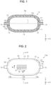
FIG. 1 is a schematic sectional view of a pressure container using a fiber structure according to a first embodiment. -
FIG. 2 is a schematic side view of a pressure container precursor according to the first embodiment. -
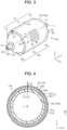
FIG. 3 is a perspective view of the pressure container precursor according to the first embodiment. -
FIG. 4 is a sectional view of the pressure container, taken along line IV-IV inFIG. 2 . -
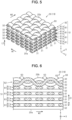
FIG. 5 is a partially enlarged perspective view of the fiber structure according to the first embodiment. -
FIG. 6 is a sectional view of the fiber structure according to the first embodiment. -
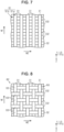
FIG. 7 is a plan view of a first fiber layer according to the first embodiment. -
FIG. 8 is a plan view of a second fiber layer according to the first embodiment. -
FIG. 9 is a schematic view of the fiber structure according to the first embodiment, explaining a method for manufacturing the fiber structure. -
FIG. 10 is a schematic view of the fiber structure according to the first embodiment, explaining the method for manufacturing the fiber structure. -
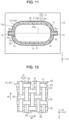
FIG. 11 is a schematic view of the fiber structure according to the first embodiment, explaining impregnation of the fiber structure with resin. -
FIG. 12 is a plan view of a first fiber layer according to a second embodiment. -
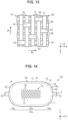
FIG. 13 is a plan view of a first fiber layer according to another embodiment. -
FIG. 14 is a schematic side view of a pressure container precursor using a fiber structure according to another embodiment. -
FIG. 15 is a plan view of a second fiber layer according to another embodiment. - The following will describe a fiber structure according to a first embodiment with reference to accompanying
FIGS. 1 to 11 . The following will describe an example of the fiber structure that is used for a pressure container. For the sake of explanation, the fiber structure will be explained after explanation of the pressure container. The figures show X-axis, Y-axis, and Z-axis that are perpendicular to each other. In the following description, a direction parallel to the X-axis is referred to as an axial direction X. - As illustrated in
FIG. 1 , a pressure container 10 includes a fiber-reinforcedcomposite material 11 and aliner 12. The pressure container 10 according to the present embodiment is a high-pressure tank for storing hydrogen gas. Theliner 12 is made of a resin material, for example. The fiber-reinforcedcomposite material 11 includes afiber structure 19. Thefiber structure 19 is impregnated with thermosetting resin as a resin matrix Ma. The fiber-reinforcedcomposite material 11 is formed by impregnating thefiber structure 19 with thermosetting resin by RTM. Examples of thermosetting resin include epoxy resin, vinyl ester resin, unsaturated polyester resin, and phenolic resin. Theliner 12 is reinforced by the fiber-reinforcedcomposite material 11 to secure the pressure capacity of the pressure container 10. - The following will the configuration of a
pressure container precursor 10a of the pressure container 10. - As illustrated in
FIG. 2 , thepressure container precursor 10a includes thefiber structure 19 and theliner 12. Thefiber structure 19 of thepressure container precursor 10a is afiber preform 19a for manufacturing the pressure container 10 by impregnating thefiber structure 19 with thermosetting resin. - The
pressure container precursor 10a is different from the pressure container 10 in that thepressure container precursor 10a does not include the fiber-reinforcedcomposite material 11. Excluding this difference, thepressure container precursor 10a has the same configuration as that of the pressure container 10. The following will describe the configuration of thepressure container precursor 10a with reference toFIGS. 2 to 8 , and the following explanation on the configuration of thepressure container precursor 10a is common to that of the pressure container 10 unless otherwise noted. - As illustrated in
FIG. 3 , theliner 12 includes abody 13 having a cylindrical shape anddome portions 14. In the present embodiment, thebody 13 has a circular cylindrical shape. The central axis of thebody 13 extends in the axial direction X. The central axis of thebody 13 is simply referred to as a central axis L. The central axis L corresponds to the central axis of theliner 12. Thebody 13 has thedome portions 14 respectively at opposite ends of thebody 13 in the axial direction X. Thedome portions 14 have a shape that gradually shrinks toward the top of thedome portion 14. Thebody 13 and thedome portions 14 cooperate to define an inner space of theliner 12. - The
fiber structure 19 covers a linerouter surface 12a that is the outer surface of theliner 12. The linerouter surface 12a includes a bodyouter surface 13a that is the outer surface of thebody 13, and domeouter surfaces 14a that are the outer surfaces of thedome portions 14. - The
liner 12 hascaps 15 respectively at opposite ends of theliner 12 in the axial direction X. Thecaps 15 are made of a metallic material, for example. Thecaps 15 each include a connectingportion 15a connected to thedome portion 14, and a protrudingportion 15b protruding from the connectingportion 15a. - The connecting
portion 15a is disposed at the top of thedome portion 14. The protrudingportion 15b passes through thefiber structure 19. The connectingportion 15a and the protrudingportion 15b cooperate to have therein acap hole 15c. Thecap hole 15c is formed through the connectingportion 15a and the protrudingportion 15b in the axial direction X. The inner space of theliner 12 is connected to the outside of theliner 12 through thecap hole 15c. - Although not illustrated, one of the
cap holes 15c is closed by a valve attached to the corresponding one of thecaps 15. The other of thecap holes 15c is closed by a screw installed in the other of thecaps 15. - As illustrated in
FIGS. 2 and3 , thefiber structure 19 includes acylindrical body 20 having a cylindrical shape. The central axis of thecylindrical body 20 extends in the axial direction X. The central axis of thecylindrical body 20 corresponds to the central axis L. Thecylindrical body 20 includes a plurality of fiber layers 51. The fiber layers 51 are laminated on top of each other in a laminating direction LD. In the present embodiment, the fiber layers 51 cover the bodyouter surface 13a. In the present embodiment, thefiber structure 19 includes dome fiber layers 52. The dome fiber layers 52 cover the domeouter surfaces 14a of thedome portions 14. - As illustrated in
FIG. 4 , the fiber layers 51 are laminated on the bodyouter surface 13a in the laminating direction LD. The laminating direction LD is perpendicular to the linerouter surface 12a. In the present embodiment, the plurality of fiber layers 51 includes a plurality of first fiber layers 61 and asecond fiber layer 62. In the present embodiment, the multiple first fiber layers 61 are laminated on the bodyouter surface 13a in the laminating direction LD. - One of the fiber layers 51 that forms an
inner surface 20a of thecylindrical body 20 serves as aninnermost layer 51a. One of the fiber layers 51 that forms anouter surface 20b of thecylindrical body 20 serves as anoutermost layer 51b. Theinnermost layer 51a is thefiber layer 51 that is closest to thebody 13 in the laminating direction LD. Theoutermost layer 51b is thefiber layer 51 that is most distant from thebody 13 in the laminating direction LD. In the present embodiment, theoutermost layer 51b is formed of thesecond fiber layer 62. In the present embodiment, the plurality of fiber layers 51 excluding theoutermost layer 51b is formed of the first fiber layers 61. That is, in the present embodiment, theinnermost layer 51a is formed of thefirst fiber layer 61. - The
first fiber layer 61 and thesecond fiber layer 62 may be connected to each other by an interlayer connecting yarn (not illustrated) in the laminating direction LD. Furthermore, the first fiber layers 61 may be connected to each other by an interlayer connecting yarn (not illustrated). In this configuration, the two first fiber layers 61 laminated in the laminating direction LD are connected by the interlayer connecting yarn, for example. Accordingly, the fiber layers 51 may include a plurality of sets of the first fiber layers 61 connected to each other by the interlayer connecting yarn. - As illustrated in
FIGS. 5 and 6 , in the present embodiment, each of the first fiber layers 61 includes a plurality offirst yarns 31 and a plurality ofsecond yarns 32. Thefirst yarns 31 and thesecond yarns 32 are formed of reinforced fibers. Examples of the reinforced fibers include carbon fibers and glass fibers. Thefirst fiber layer 61 includes the plurality offirst yarns 31 and the plurality ofsecond yarns 32. Thefirst yarns 31 and thesecond yarns 32 have a flattened cross section. Each of thefirst yarns 31 and each of thesecond yarns 32 have approximately the same fineness. Thefirst yarn 31 and thesecond yarn 32 have the same diameter when viewed in cross section. - As illustrated in
FIG. 3 , the yarn main axis direction of thefirst yarn 31 is referred to as a first yarn main axis direction W1. The first yarn main axis direction W1 corresponds to the circumferential direction around the central axis L. The yarn main axis direction of thesecond yarn 32 on the bodyouter surface 13a is referred to as a second yarn main axis direction W2. The second yarn main axis direction W2 corresponds to the axial direction X. That is, thesecond yarn 32 extends in the yarn main axis direction different from the yarn main axis direction of thefirst yarn 31. - As illustrated in
FIGS. 6 and7 , each of the first fiber layers 61 includes afirst yarn layer 61a and asecond yarn layer 61b. Thefirst yarn layer 61a includes thefirst yarns 31 arranged in the axial direction X. Thefirst yarns 31 of thefirst yarn layer 61a are parallel to each other. Thesecond yarn layer 61b includes thesecond yarns 32 arranged in the circumferential direction of theliner 12. Thesecond yarns 32 of thesecond yarn layer 61b are parallel to each other. Thefirst yarn layer 61a and thesecond yarn layer 61b are unidirectional (UD) sheet that is formed of single directional yarns. - The
first yarn layer 61a of thefirst fiber layer 61 is laminated on thesecond yarn layer 61b in the laminating direction LD. When thefirst fiber layer 61 is viewed from the laminating direction LD, thefirst yarns 31 of thefirst yarn layer 61a are perpendicular to thesecond yarns 32 of thesecond yarn layer 61b. The first fiber layers 61 are laminated on top of each other in the laminating direction LD, so that thefirst yarn layers 61a and the second yarn layers 61b are alternately laminated in the laminating direction LD. - The
first yarns 31 of eachfirst yarn layer 61a serve as thefirst yarns 31 of thefirst fiber layer 61. Thesecond yarns 32 of eachsecond yarn layer 61b serve as thesecond yarns 32 of thefirst fiber layer 61. In the present embodiment, thefirst fiber layer 61 has a structure, i.e., a non-crimp structure, in which thesecond yarns 32 are not interlaced with thefirst yarns 31. Thefirst fiber layer 61 does not include interlacedsections 63 in which thesecond yarns 32 are interlaced with thefirst yarns 31. - As illustrated in
FIGS. 5 and 6 , thesecond fiber layer 62 includes thefirst yarns 31 and thesecond yarns 32. Thesecond fiber layer 62 is afabric 60 in which thesecond yarns 32 are interlaced with thefirst yarns 31. In the present embodiment, thesecond fiber layer 62 is a single layer fabric made by plain weaving. - As illustrated in
FIGS. 6 and8 , thesecond fiber layer 62 includes thefirst yarns 31 arranged in the axial direction X and thesecond yarns 32 arranged in the circumferential direction of theliner 12. Thefirst yarns 31 of thesecond fiber layer 62 are parallel to each other. Thesecond yarns 32 of thesecond fiber layer 62 are parallel to each other. When thesecond fiber layer 62 is viewed from the laminating direction LD, thefirst yarns 31 are perpendicular to thesecond yarns 32 in thesecond fiber layer 62. - The
first yarns 31 continuously extend between thefirst fiber layer 61 and thesecond fiber layer 62. In the present embodiment, thefirst yarns 31 continuously extend between all the fiber layers 51 laminated in the laminating direction LD. - The
second fiber layer 62 includes the interlacedsections 63 in which thesecond yarns 32 are interlaced with thefirst yarns 31. In the present embodiment, because thesecond fiber layer 62 is made by plain weaving, thesecond fiber layer 62 includes the same number of the interlacedsections 63 as the number of intersections of thesecond yarns 32 and thefirst yarns 31. Since thefirst fiber layer 61 does not include the interlacedsections 63, in the present embodiment, the number of the interlacedsections 63 of thesecond fiber layer 62 is more than that of thefirst fiber layer 61. - As illustrated in
FIG. 3 , the dome fiber layers 52 are laminated on each of the domeouter surfaces 14a in the laminating direction LD. In the present embodiment, each of the dome fiber layers 52 is thefabric 60 that includes thefirst yarns 31 and thesecond yarns 32. In the present embodiment, thedome fiber layer 52 is a single layer fabric made by plain weaving. Thefirst yarns 31 and thesecond yarns 32 on the domeouter surface 14a extend in their yarn main axis directions on the bodyouter surface 13a and are curved along the domeouter surface 14a. - The dome fiber layers 52 may be connected by an interlayer connecting yarn (not illustrated) in the laminating direction LD. Furthermore, the dome fiber layers 52 may be connected to each other by the interlayer connecting yarn (not illustrated). In this configuration, for example, the two adjacent dome fiber layers 52 laminated in the laminating direction LD are connected by the interlayer connecting yarn. Accordingly, the dome fiber layers 52 may include a plurality of sets of the dome fiber layers 52 that are connected to each other by the interlayer connecting yarn.
- In the present embodiment, the
first yarns 31 continuously extend between all the dome fiber layers 52 laminated in the laminating direction LD. Thesecond yarns 32 continuously extend between the fiber layers 51 and the dome fiber layers 52, so that the dome fiber layers 52 are integrated with the fiber layers 51. - The following will describe a method for manufacturing the
fiber structure 19 with reference toFIGS. 9 and 10 . - As illustrated in
FIG. 9 , thefiber structure 19 is manufactured such that theliner 12 is rotated about the central axis L. Accordingly, thefiber structure 19 wound around theliner 12 is manufactured. Thefirst yarns 31 serve as warp. Thesecond yarns 32 serves as weft. Thefirst yarns 31 are supplied from a warp beam toward theliner 12. Thefirst yarns 31 are moved up and down by a heddle to form a passage between thefirst yarns 31. - The
first yarns 31 drawn from the warp beam are fixed, at the ends of thefirst yarns 31, to the bodyouter surface 13a or the domeouter surface 14a. Thefirst yarns 31, the ends of which are fixed to the domeouter surface 14a, serve asdome warp yarns 31a. Thefirst yarns 31, the ends of which are fixed to the bodyouter surface 13a, serve asbody warp yarns 31b. - To form each
dome fiber layer 52, firstly, thesecond yarns 32 are inserted into a passage formed between thedome warp yarns 31a. Thesecond yarns 32 are interlaced with thedome warp yarns 31a. The actions of forming the passage between thedome warp yarns 31a and inserting thesecond yarns 32 into the passage between thedome warp yarns 31a are repeatedly performed with repetition of beating by a reed. In this way, thedome fiber layer 52 is woven on the domeouter surface 14a. Thedome fiber layer 52 is made by plain weaving with thefirst yarns 31 and thesecond yarns 32. - The
second yarns 32 are repeatedly inserted into the passage between thedome warp yarns 31a while theliner 12 is rotated. Accordingly, the multiple dome fiber layers 52 are laminated on the domeouter surface 14a in the laminating direction LD. In this way, the dome fiber layers 52 are formed. - The
dome warp yarns 31a are wound around theliner 12 with the rotation of theliner 12. Thedome warp yarns 31a are used for forming the dome fiber layers 52, so that thefirst yarns 31 continuously extend between all the dome fiber layers 52. - As well as the
dome warp yarns 31a, thebody warp yarns 31b are wound around theliner 12. Thebody warp yarns 31b are used for forming eachfiber layer 51. Accordingly, in the present embodiment, thefirst yarns 31 continuously extend between the first fiber layers 61 and thesecond fiber layer 62. - The
fiber layer 51 is formed while thedome fiber layer 52 is formed. To form thefiber layer 51, in the present embodiment, thesecond yarns 32 inserted into the passage between thedome warp yarns 31a are inserted into a space between thebody warp yarns 31b and the bodyouter surface 13a. Thesecond yarns 32 are inserted through the passage between thedome warp yarns 31a of thedome fiber layer 52 on the one domeouter surface 14a into the space between thebody warp yarns 31b and the bodyouter surface 13a, and subsequently inserted into the passage between thedome warp yarns 31a of thedome fiber layer 52 on the other domeouter surface 14a. Thesecond yarns 32 are not interlaced with thebody warp yarns 31b. - The
second yarns 32 are repeatedly inserted into the space between thebody warp yarns 31b and the bodyouter surface 13a. Accordingly, thesecond yarn layer 61b is formed on the bodyouter surface 13a. Thefirst yarn layer 61a is laminated on thesecond yarn layer 61b in the laminating direction LD. In this way, thefirst fiber layer 61 as theinnermost layer 51a is formed. - After the
innermost layer 51a is formed, thesecond yarns 32 are repeatedly inserted into a space between thebody warp yarns 31b and thefirst fiber layer 61 previously formed. As when theinnermost layer 51a is formed, thesecond yarns 32, which have been inserted through the passage between thedome warp yarns 31a, are inserted into the space between thebody warp yarns 31b and thefirst fiber layer 61. Thefirst yarn layer 61a is laminated on thesecond yarn layer 61b in the laminating direction LD so that thefirst yarn layers 61a and the second yarn layers 61b are alternately laminated on top of each other. The multiple first fiber layers 61 are laminated on the bodyouter surface 13a in the laminating direction LD. In this way, the fiber layers 51 excluding theoutermost layer 51b are formed as the first fiber layers 61. - In
FIGS. 9 and 10 , thesecond yarns 32 of each of the fiber layers 51 excluding theoutermost layer 51b are illustrated by broken lines. Thesecond yarns 32 of the dome fiber layers 52 and theoutermost layer 51b are illustrated by solid lines. - As illustrated in
FIG. 10 , to form theoutermost layer 51b, thesecond yarns 32 are inserted into the passage formed between thebody warp yarns 31b. As when the fiber layers 51 excluding theoutermost layer 51b are formed, thesecond yarns 32, which have been inserted through the passage between thedome warp yarns 31a, are inserted into the passage between thebody warp yarns 31b. Thesecond yarns 32 of theoutermost layer 51b are interlaced with thebody warp yarns 31b. The actions of forming the passage between thebody warp yarns 31b and inserting thesecond yarns 32 into the passage between thebody warp yarns 31b are repeatedly performed with repetition of beating by a reed. In this way, thesecond fiber layer 62 is woven as theoutermost layer 51b. Thesecond fiber layer 62 is made by plain weaving with thefirst yarns 31 and thesecond yarns 32. In this way, the fiber layers 51 are formed. Thefiber structure 19 is manufactured by forming the fiber layers 51 and the dome fiber layers 52. - The following will describe a method for impregnating the
fiber structure 19 with resin with reference toFIG. 11 . - As illustrated in
FIG. 11 , thepressure container precursor 10a including thefiber structure 19 is placed in a formingmold 70 after thefiber structure 19 is formed on the linerouter surface 12a. Thefiber structure 19 is impregnated with the resin matrix Ma by RTM. In this way, the pressure container 10 having the linerouter surface 12a covered with the fiber-reinforcedcomposite material 11 is formed. - Although not illustrated, the forming
mold 70 is formed of a plurality of members. The plurality of members assembled define an enclosed space S in the formingmold 70. Thepressure container precursor 10a is placed in the enclosed space S. - The forming
mold 70 has aresin flow passage 71. The resin matrix Ma is injected to the enclosed space S through theresin flow passage 71. The resin matrix Ma fills a gap between the formingmold 70 and thepressure container precursor 10a. Accordingly, the dome fiber layers 52 are impregnated with the resin matrix Ma. The fiber layers 51 are impregnated with the resin matrix Ma sequentially from theoutermost layer 51b to theinnermost layer 51a. - After the
fiber structure 19 is impregnated with the resin matrix Ma, thefiber structure 19 is heated by the formingmold 70 to a temperature sufficient to thermally cure the resin matrix Ma. The temperature is set to a curing temperature of epoxy resin, which is used as the resin matrix Ma. The resin matrix Ma in thefiber structure 19 is cured with heat by the formingmold 70. - The whole of the resin matrix Ma in the
fiber structure 19 is thermally cured, so that the fiber-reinforcedcomposite material 11 is formed. In this way, the pressure container 10 including the fiber-reinforcedcomposite material 11 is manufactured. The pressure container 10 is cooled and removed from the formingmold 70. - The following will describe the operation according to the present embodiment.
- In the present embodiment, the
second yarns 32 are interlaced with thefirst yarns 31 in the interlacedsections 63, and the number of the interlacedsections 63 of thesecond fiber layer 62 is more than that of thefirst fiber layer 61. The first fiber layers 61 form the fiber layers 51 excluding theoutermost layer 51b. Thesecond fiber layer 62 forms theoutermost layer 51b. - The resin matrix Ma fills the gap between the forming
mold 70 and thepressure container precursor 10a. Thefiber layer 51 as theoutermost layer 51b is subjected to impregnation resistance of the resin matrix Ma. In the present embodiment, theoutermost layer 51b subjected to the impregnation resistance of the resin matrix Ma, and the number of the interlacedsections 63 of theoutermost layer 51b is more than the number of the interlacedsections 63 of each of the fiber layers 51 excluding theoutermost layer 51b. Accordingly, the reinforced fibers of theoutermost layer 51b are unlikely to become wavy, which may be caused by the impregnation resistance of the resin matrix Ma. - In the present embodiment, each of the first fiber layers 61 has a structure, i.e., a non-crimp structure, in which the
second yarns 32 are not interlaced with thefirst yarns 31. In other words, the number of the interlacedsections 63 of thefirst fiber layer 61 is less than that of thesecond fiber layer 62. When thefiber structure 19 is impregnated with the resin matrix Ma, the impregnation resistance of the resin matrix Ma is reduced by theoutermost layer 51b. Then the fiber layers 51 excluding theoutermost layer 51b are subjected to the impregnation resistance of the resin matrix Ma. Accordingly, the reinforced fibers of the fiber layers 51 excluding theoutermost layer 51b are unlikely to become wavy, which may be caused by the impregnation resistance of the resin matrix Ma. - The
second yarns 32 in the first fiber layers 61 do not become wavy, which may be caused by the interlacement of thesecond yarns 32 with thefirst yarns 31. This increases the strength of the fiber-reinforcedcomposite material 11 without increasing the number or thickness of thefirst yarns 31 and thesecond yarns 32 of thefiber structure 19. According to the present embodiment, the first fiber layers 61 form the fiber layers 51 excluding theoutermost layer 51b, and this configuration suppresses an increase in weight of the fiber-reinforcedcomposite material 11. - The first embodiment achieves the following advantageous effects.
- (1) According to the embodiment, the
outermost layer 51b is formed of thesecond fiber layer 62. Thesecond yarns 32 are interlaced with thefirst yarns 31 in the interlacedsections 63, and the number of the interlacedsections 63 of thesecond fiber layer 62 is more than that of thefirst fiber layer 61. Accordingly, the reinforced fibers of thesecond fiber layer 62 are unlikely to become wavy, which may be caused by the impregnation resistance of thermosetting resin. This suppresses a decrease in the pressure capacity and the fatigue strength of the fiber-reinforcedcomposite material 11 formed of thefiber structure 19. According to the embodiment, the number of the interlacedsections 63 of thefirst fiber layer 61 is less than that of thesecond fiber layer 62. Accordingly, thesecond yarns 32 of the first fiber layers 61 are less likely to become wavy, which may be caused by interlacement of thesecond yarns 32 with thefirst yarns 31, as compared with thesecond yarns 32 of thesecond fiber layer 62. The multiple fiber layers 51 include the first fiber layers 61, thereby increasing the strength of the fiber-reinforcedcomposite material 11 formed of thefiber structure 19. This increases the strength of the fiber-reinforcedcomposite material 11 without increasing the number or thickness of thefirst yarns 31 and thesecond yarns 32 of thefiber structure 19, thereby suppressing an increase in weight of the fiber-reinforcedcomposite material 11. This therefore suppresses a decrease in the pressure capacity and the fatigue strength and an increase in weight of a fiber-reinforcedcomposite material 11 formed of afiber structure 19, and increases the strength of the fiber-reinforcedcomposite material 11. - (2) The
first yarns 31 continuously extend between the first fiber layers 61 and thesecond fiber layer 62. This increases the strength of thefiber structure 19 in the yarn main axis direction of thefirst yarns 31, as compared with a configuration in which thefirst yarns 31 do not continuously extend between the first fiber layers 61 and thesecond fiber layer 62. This further increases the strength of the fiber-reinforcedcomposite material 11 formed of thefiber structure 19. - The following will describe a
fiber structure 19 according to a second embodiment with reference to accompanyingFIGS. 4 ,8 , and12 . The second embodiment is different from the first embodiment in that each of the first fiber layers 61 does not include thefirst yarn layers 61a and the second yarn layers 61b. The following description will focus on such a difference. The same elements as in the first embodiment are denoted by the same reference numbers and are not elaborated here. - As illustrated in
FIGS. 4 and12 , in the present embodiment, each of the first fiber layers 61 does not include thefirst yarn layer 61a and thesecond yarn layer 61b of the first embodiment. Thefirst fiber layer 61 is thefabric 60 in which thesecond yarns 32 are interlaced with thefirst yarns 31. That is, thefirst fiber layer 61 and thesecond fiber layer 62 are each formed of thefabric 60. In the present embodiment, thefirst fiber layer 61 and thesecond fiber layer 62 include the interlacedsections 63 in which thesecond yarns 32 are interlaced with thefirst yarns 31. In the present embodiment, thefirst fiber layer 61 is made by twill weaving. For example, in thefirst fiber layer 61, thesecond yarns 32 are interlaced with thefirst yarns 31 by passing over onefirst yarn 31 then under twofirst yarns 31. - The
first fiber layer 61 includes thefirst yarns 31 and thesecond yarns 32. The first yarn main axis direction W1 of thefirst yarns 31 of thefirst fiber layer 61 corresponds to the circumferential direction around the central axis L. The second yarn main axis direction W2 of thesecond yarns 32 of thefirst fiber layer 61 corresponds to the axial direction X. That is, thesecond yarn 32 extends in the yarn main axis direction different from the yarn main axis direction of thefirst yarn 31. Thefirst yarns 31 of thefirst fiber layer 61 are arranged parallel to each other in the axial direction X. Thesecond yarns 32 of thefirst fiber layer 61 are arranged parallel to each other in the circumferential direction of theliner 12. When thefirst fiber layer 61 is viewed from the laminating direction LD, thefirst yarns 31 are perpendicular to thesecond yarns 32 in thefirst fiber layer 61. Thefirst yarns 31 continuously extend between the first fiber layers 61 and thesecond fiber layer 62. - In the present embodiment, each of the dome fiber layers 52 is the
fabric 60 that includes thefirst yarns 31 and thesecond yarns 32, like the first embodiment. In the present embodiment, thedome fiber layer 52 is a single layer fabric made by plain weaving. Thefirst yarns 31 continuously extend between all the dome fiber layers 52 laminated in the laminating direction LD. Thesecond yarns 32 continuously extend between the fiber layers 51 and thedome fiber layer 52. - As illustrated in
FIGS. 8 and12 , in the present embodiment, thesecond fiber layer 62 is a single layer fabric made by plain weaving, like the first embodiment. Accordingly, in the present embodiment, thesecond fiber layer 62 includes the same number of the interlacedsections 63 as the number of intersections of thesecond yarns 32 and thefirst yarns 31. In the present embodiment, the number of the interlacedsections 63 of thesecond fiber layer 62 is more than that of thefirst fiber layer 61. - As illustrated in
FIGS. 4 and12 , in the present embodiment, thesecond yarns 32 are repeatedly inserted into the passage formed between thebody warp yarns 31b to form each of the first fiber layers 61. In this way, thefirst fiber layer 61 as theinnermost layer 51a is woven. The multiple first fiber layers 61 are laminated on the bodyouter surface 13a in the laminating direction LD. In this way, the fiber layers 51 excluding theoutermost layer 51b are formed as the first fiber layers 61. Thesecond fiber layer 62 and the dome fiber layers 52 are formed in the same manner as those of the first embodiment. Thefiber structure 19 is manufactured by forming the fiber layers 51 and the dome fiber layers 52. Thefiber structure 19 is impregnated with the resin matrix Ma by RTM like the first embodiment, so that the pressure container 10 having the linerouter surface 12a covered with the fiber-reinforcedcomposite material 11 is formed. - The following will describe the operation according to the present embodiment.
- In the present embodiment, the
second yarns 32 are interlaced with thefirst yarns 31 in the interlacedsections 63, and the number of the interlacedsections 63 of thesecond fiber layer 62 is more than that of eachfirst fiber layer 61. The first fiber layers 61 form the fiber layers 51 excluding theoutermost layer 51b. Thesecond fiber layer 62 forms theoutermost layer 51b. Accordingly, the reinforced fibers of the fiber layers 51 are unlikely to become wavy, which may be caused by the impregnation resistance of the resin matrix Ma, like the first embodiment. - The
second yarns 32 of the first fiber layers 61 are less likely to become wavy, which may be caused by interlacement of thesecond yarns 32 with thefirst yarns 31, as compared with thesecond yarns 32 of thesecond fiber layer 62. The first fiber layers 61 form the fiber layers 51 excluding theoutermost layer 51b, and this configuration suppresses an increase in weight of the fiber-reinforcedcomposite material 11 and increases the strength of the fiber-reinforcedcomposite material 11. - The second embodiment achieves the same advantageous effects as those of the first embodiment.
- The
fiber structure 19 according to the embodiments may be modified as described below. The embodiments may be combined with the following modifications within technically consistent range. - ∘ As illustrated in
FIG. 13 , each of the first fiber layers 61 according to the second embodiment may be made by satin weaving. For example, in thefirst fiber layer 61 of this modification example, thesecond yarns 32 are interlaced with thefirst yarns 31 by passing over onefirst yarns 31 then under fourfirst yarn 31. In this modification example, thefirst fiber layer 61 is thefabric 60 in which thesecond yarns 32 are interlaced with thefirst yarns 31. That is, thefirst fiber layer 61 and thesecond fiber layer 62 are each formed of thefabric 60. In the present embodiment, thefirst fiber layer 61 and thesecond fiber layer 62 include the interlacedsections 63 in which thesecond yarns 32 are interlaced with thefirst yarns 31. Thesecond fiber layer 62 is a single layer fabric made by plain weaving, like the aforementioned embodiments. Accordingly, thesecond fiber layer 62 includes the same number of the interlacedsections 63 as the number of intersections of thesecond yarns 32 and thefirst yarns 31. In this modification example, the number of the interlacedsections 63 of thesecond fiber layer 62 is more than that of thefirst fiber layer 61. Accordingly, this modification example achieves the same advantageous effects as those of the embodiments. - ∘ The
second fiber layer 62 is made by plain weaving in the second embodiment, but thesecond fiber layer 62 is not limited thereto. For example, thesecond fiber layer 62 may be made by twill weaving. In this case, for example, thefirst fiber layer 61 is made by satin weaving. The number of the interlacedsections 63 of thesecond fiber layer 62 is more than that of thefirst fiber layer 61. - ∘ In the first embodiment, the
first fiber layer 61 has to include at least one of thefirst yarn 31 and thesecond yarn 32. For example, thefirst yarn layer 61a or thesecond yarn layer 61b may be removed from thefirst fiber layer 61. In this configuration, thefirst fiber layer 61 includes either thefirst yarns 31 or thesecond yarns 32. - ∘ The
first yarns 31 may not continuously extend between the first fiber layers 61 and thesecond fiber layer 62. - ∘ In the second embodiment, the first fiber layers 61 may be partly different. For example, the first fiber layers 61 may be partly different in weave or yarns. If the first fiber layers 61 may be partly different in weave, for example, a part of the first fiber layers 61 may be made by twill weaving and the rest of the first fiber layers 61 may be made by satin weaving. In this configuration, the number of the interlaced
sections 63 of thesecond fiber layer 62, which is made by plain weaving, is more than that of eachfirst fiber layer 61. If the first fiber layers 61 may be partly different in yarns, for example, a part of the first fiber layers 61 may include thefirst yarns 31 and thesecond yarns 32 and the rest of the first fiber layers 61 may include either thefirst yarns 31 or thesecond yarns 32. - ∘ As illustrated in
FIGS. 14 and15 , in the first embodiment and the second embodiment, thesecond fiber layer 62 may be abraid 75. That is, thesecond fiber layer 62 is not limited to thefabric 60. Specifically, thesecond fiber layer 62 according to the modification example includes the plurality offirst yarns 31 and the plurality ofsecond yarns 32. Thefirst yarns 31 and thesecond yarns 32 cross each other. For example, thefirst yarns 31 and a center line C, which is parallel to the central axis L, cross each other at a first angle A1. For example, thesecond yarns 32 and the center line C cross each other at a second angle A2. For example, the first angle A1 is 60°. For example, the second angle A2 is -60°. In this modification example, thesecond fiber layer 62 includes the same number of the interlacedsections 63 as the number of intersections of thesecond yarns 32 and thefirst yarns 31. In this modification example, the number of the interlacedsections 63 of thesecond fiber layer 62 is more than that of thefirst fiber layer 61. Accordingly, this modification example achieves the same advantageous effects as those of the embodiments. - ∘ In the first embodiment and the second embodiment, the plurality of dome fiber layers 52 is not limited to plain weave fabric. For example, the dome fiber layers 52 may be formed of
fabrics 60 made by weaving other than plain weaving. For example, the dome fiber layers 52 may be made by twill weaving or satin weaving. For example, the dome fiber layers 52 may include dome fiber layers 52 that are formed of thefabrics 60, and dome fiber layers 52 that are formed ofbraids 75 and externally cover the dome fiber layers 52 formed of thefabrics 60. - ∘ In the first embodiment and the second embodiment, the
innermost layer 51a may be formed of thesecond fiber layer 62. In this configuration, for example, the fiber layers 51 excluding theinnermost layer 51a may be formed of the first fiber layers 61. Examples of the method for impregnating thefiber structure 19 with the resin matrix Ma by RTM include filling the resin matrix Ma into a gap between the linerouter surface 12a and thefiber structure 19. In this method, thecaps 15 of theliner 12 have a resin passage between the linerouter surface 12a and thefiber structure 19. The resin matrix Ma is filled into thefiber structure 19 through the resin passage. Thefiber layer 51 as theinnermost layer 51a is subjected to impregnation resistance of the resin matrix Ma. In this modification example, thesecond fiber layer 62 is formed of theinnermost layer 51a that is subjected to the impregnation resistance of the resin matrix Ma. The number of the interlacedsections 63 of thesecond fiber layer 62 is more than that of thefirst fiber layer 61. Accordingly, the reinforced fibers of theinnermost layer 51a are unlikely to become wavy, which may be caused by the impregnation resistance of the resin matrix Ma. Both of theinnermost layer 51a and theoutermost layer 51b may be formed of thesecond fiber layer 62. In this configuration, for example, the fiber layers 51 excluding theinnermost layer 51a and theoutermost layer 51b may be formed of the first fiber layers 61. - ∘ The
liner 12 may be made of a metallic material. - ∘ The
liner 12 may be integrally formed with thecaps 15. - ∘ The pressure container 10 is not limited to a container that is mounted to a fuel-cell electric vehicle as a hydrogen source, and may be used as a hydrogen source of a hydrogen engine or applicable to a heat pump and the like. The pressure container 10 may be used as a hydrogen source for a fuel cell for household use.
- ∘ The pressure container 10 is not limited to a container for storing hydrogen gas. The pressure container 10 may store gas, such as compressed natural gas (CNG) or liquid natural gas (LNG).
- ∘ The shape of the
fiber structure 19 may be modified except for the shape of thecylindrical body 20. That is, thefiber structure 19 has to include thecylindrical body 20. For example, thefiber structure 19 may not include at least one of the dome fiber layers 52 on one side of thecylindrical body 20 and the dome fiber layers 52 on the other side of thecylindrical body 20 in the axial direction X. For example, in thefiber structure 19, at least one of opposite sides of thecylindrical body 20 in the axial direction X may include fiber layers that are different from the dome fiber layers 52. - ∘ The
fiber structure 19 may be afiber preform 19a used for a purpose other than the pressure container 10. -
- LD Laminating direction
- W1 First yarn main axis direction
- W2 Second yarn main axis direction
- 11 Fiber-reinforced composite material
- 19 Fiber structure
- 20 Cylindrical body
- 20a Inner surface
- 20b Outer surface
- 31 First yarn
- 32 Second yarn
- 51 Fiber layer
- 51a Innermost layer
- 51b Outermost layer
- 60 Fabric
- 61 First fiber layer
- 62 Second fiber layer
- 63 Interlaced section
Claims (3)
- A fiber structure impregnated with thermosetting resin by RTM to form a fiber-reinforced composite material, the fiber structure comprising:a cylindrical body having a cylindrical shape, whereinthe cylindrical body has a plurality of fiber layers laminated on top of each other in a laminating direction,the plurality of fiber layers includes:a first fiber layer including at least one of a first yarn and a second yarn extending in a yarn main axis direction that is different from a yarn main axis direction of the first yarn; anda second fiber layer including the first yarn and the second yarn, the first yarn and the second yarn are formed of reinforced fibers,the first fiber layer does not include interlaced sections in which the second yarn is interlaced with the first yarn,one of the fiber layers that forms an inner surface of the cylindrical body serves as an innermost layer, and another one of the fiber layers that forms an outer surface of the cylindrical body serves as an outermost layer, andat least one of the innermost layer and the outermost layer is formed of the second fiber layer, and the second fiber layer includes the interlaced sections.
- A fiber structure impregnated with thermosetting resin by RTM to form a fiber-reinforced composite material, the fiber structure comprising:a cylindrical body having a cylindrical shape, whereinthe cylindrical body has a plurality of fiber layers laminated on top of each other in a laminating direction,the plurality of fiber layers includes:a first fiber layer including a first yarn and a second yarn extending in a yarn main axis direction that is different from a yarn main axis direction of the first yarn; anda second fiber layer including the first yarn and the second yarn, the first yarn and the second yarn are formed of reinforced fibers,the first fiber layer and the second fiber layer each include interlaced sections in which the second yarn is interlaced with the first yarn,at least one of the first fiber layer and the second fiber layer is formed of a fabric,one of the fiber layers that forms an inner surface of the cylindrical body serves as an innermost layer, and another one of the fiber layers that forms an outer surface of the cylindrical body serves as an outermost layer, andat least one of the innermost layer and the outermost layer is formed of the second fiber layer, and the number of the interlaced sections of the second fiber layer is more than the number of the interlaced sections of the first fiber layer.
- The fiber structure according to claim 1 or 2, whereinthe first fiber layer includes the first yarn, andthe first yarn continuously extends between the first fiber layer and the second fiber layer.
Applications Claiming Priority (2)
| Application Number | Priority Date | Filing Date | Title |
|---|---|---|---|
| JP2021094652A JP7687061B2 (en) | 2021-06-04 | 2021-06-04 | Fiber Structure |
| PCT/JP2022/010357 WO2022254860A1 (en) | 2021-06-04 | 2022-03-09 | Fiber structure |
Publications (2)
| Publication Number | Publication Date |
|---|---|
| EP4349588A1 true EP4349588A1 (en) | 2024-04-10 |
| EP4349588A4 EP4349588A4 (en) | 2024-10-02 |
Family
ID=84324239
Family Applications (1)
| Application Number | Title | Priority Date | Filing Date |
|---|---|---|---|
| EP22815617.0A Pending EP4349588A4 (en) | 2021-06-04 | 2022-03-09 | Fiber structure |
Country Status (5)
| Country | Link |
|---|---|
| US (1) | US20240239056A1 (en) |
| EP (1) | EP4349588A4 (en) |
| JP (1) | JP7687061B2 (en) |
| CN (1) | CN117396543A (en) |
| WO (1) | WO2022254860A1 (en) |
Family Cites Families (14)
| Publication number | Priority date | Publication date | Assignee | Title |
|---|---|---|---|---|
| US5952067A (en) | 1996-12-02 | 1999-09-14 | A&P Technology, Inc. | Braided structure having uncrimped strands |
| US9017814B2 (en) * | 2007-10-16 | 2015-04-28 | General Electric Company | Substantially cylindrical composite articles and fan casings |
| US7905972B2 (en) * | 2007-10-16 | 2011-03-15 | General Electric Company | Methods for making substantially cylindrical articles and fan casings |
| US20140003923A1 (en) * | 2012-07-02 | 2014-01-02 | Peter Finnigan | Functionally graded composite fan containment case |
| US9539789B2 (en) * | 2012-08-21 | 2017-01-10 | Kabushiki Kaisha Toyota Jidoshokki | Three-dimensional fiber-reinforced composite and method for producing three-dimensional fiber-reinforced composite |
| US9415566B2 (en) * | 2012-08-21 | 2016-08-16 | Kabushiki Kaisha Toyota Jidoshokki | Three-dimensional fiber-reinforced composite material |
| WO2014030633A1 (en) * | 2012-08-21 | 2014-02-27 | 株式会社 豊田自動織機 | Three-dimensional fiber-reinforced composite |
| US20160101592A1 (en) * | 2013-06-18 | 2016-04-14 | E I Du Pont De Nemours And Company | Hybrid glass fibers carbon fibers thermoplastic composites |
| FR3037855B1 (en) * | 2015-06-25 | 2017-07-14 | Rehau Entreprise Sarl | REINFORCING BANDS FOR TUBULAR PIECE OF COMPOSITE MATERIAL |
| JP2018178289A (en) * | 2017-04-07 | 2018-11-15 | 株式会社豊田自動織機 | Preform and fiber-reinforced composite material |
| JP6729472B2 (en) * | 2017-04-20 | 2020-07-22 | 株式会社豊田自動織機 | Fiber structure, pressure vessel, and method for manufacturing fiber structure |
| JP2019151072A (en) * | 2018-03-06 | 2019-09-12 | 株式会社豊田自動織機 | Fiber structure and pressure vessel |
| JP2021025164A (en) * | 2019-08-06 | 2021-02-22 | 株式会社豊田自動織機 | Fiber structure and fiber-reinforce composite material |
| US11401631B2 (en) * | 2019-10-28 | 2022-08-02 | Federal-Mogul Powertrain Llc | Impact resistant, wrappable multilayered woven sleeve and method of construction thereof |
-
2021
- 2021-06-04 JP JP2021094652A patent/JP7687061B2/en active Active
-
2022
- 2022-03-09 US US18/290,232 patent/US20240239056A1/en active Pending
- 2022-03-09 EP EP22815617.0A patent/EP4349588A4/en active Pending
- 2022-03-09 CN CN202280037731.6A patent/CN117396543A/en active Pending
- 2022-03-09 WO PCT/JP2022/010357 patent/WO2022254860A1/en not_active Ceased
Also Published As
| Publication number | Publication date |
|---|---|
| US20240239056A1 (en) | 2024-07-18 |
| EP4349588A4 (en) | 2024-10-02 |
| JP2022186431A (en) | 2022-12-15 |
| CN117396543A (en) | 2024-01-12 |
| WO2022254860A1 (en) | 2022-12-08 |
| JP7687061B2 (en) | 2025-06-03 |
Similar Documents
| Publication | Publication Date | Title |
|---|---|---|
| CN110520667B (en) | Fiber structure, pressure vessel, and manufacturing method of fiber structure | |
| US11549643B2 (en) | Pressure vessel and pressure-vessel manufacturing method | |
| CN107850259B (en) | Pressure Vessels with Reinforced Heads | |
| CA2775894C (en) | Woven preform, composite, and method of making thereof | |
| EP2483044B1 (en) | Woven preform, composite, and method of making thereof | |
| US20150314553A1 (en) | Reinforced structural component made of composite material | |
| CN111503265B (en) | High-pressure tank and method for manufacturing high-pressure tank | |
| JP7111049B2 (en) | Textile structures and pressure vessels | |
| WO2019171889A1 (en) | Fiber structure and pressure container | |
| US11427939B2 (en) | FRP tubular body and method for manufacturing FRP tubular body | |
| US20240239056A1 (en) | Fiber structure | |
| US10697094B2 (en) | Fiber structure and fiber reinforced composite material | |
| JP7040347B2 (en) | Pressure vessel and manufacturing method of pressure vessel | |
| JP7040346B2 (en) | Pressure vessel and manufacturing method of pressure vessel | |
| JP7798636B2 (en) | Fiber Structure | |
| WO2012014613A1 (en) | Fiber substrate and fiber-reinforced composite material | |
| JP2021025164A (en) | Fiber structure and fiber-reinforce composite material | |
| JP2021091976A (en) | Fiber structure | |
| WO2012014605A1 (en) | Fiber substrate and fiber-reinforced composite material | |
| JP2021091977A (en) | Fiber structure | |
| JP2021091106A (en) | Fiber preform for pressure vessel |
Legal Events
| Date | Code | Title | Description |
|---|---|---|---|
| STAA | Information on the status of an ep patent application or granted ep patent |
Free format text: STATUS: THE INTERNATIONAL PUBLICATION HAS BEEN MADE |
|
| PUAI | Public reference made under article 153(3) epc to a published international application that has entered the european phase |
Free format text: ORIGINAL CODE: 0009012 |
|
| STAA | Information on the status of an ep patent application or granted ep patent |
Free format text: STATUS: REQUEST FOR EXAMINATION WAS MADE |
|
| 17P | Request for examination filed |
Effective date: 20231009 |
|
| AK | Designated contracting states |
Kind code of ref document: A1 Designated state(s): AL AT BE BG CH CY CZ DE DK EE ES FI FR GB GR HR HU IE IS IT LI LT LU LV MC MK MT NL NO PL PT RO RS SE SI SK SM TR |
|
| P01 | Opt-out of the competence of the unified patent court (upc) registered |
Free format text: CASE NUMBER: APP_38600/2024 Effective date: 20240627 |
|
| DAV | Request for validation of the european patent (deleted) | ||
| DAX | Request for extension of the european patent (deleted) | ||
| A4 | Supplementary search report drawn up and despatched |
Effective date: 20240902 |
|
| RIC1 | Information provided on ipc code assigned before grant |
Ipc: D03D 11/02 20060101ALI20240827BHEP Ipc: C08J 5/04 20060101ALI20240827BHEP Ipc: D03D 1/00 20060101ALI20240827BHEP Ipc: B32B 5/26 20060101AFI20240827BHEP |
|
| GRAP | Despatch of communication of intention to grant a patent |
Free format text: ORIGINAL CODE: EPIDOSNIGR1 |
|
| STAA | Information on the status of an ep patent application or granted ep patent |
Free format text: STATUS: GRANT OF PATENT IS INTENDED |
|
| INTG | Intention to grant announced |
Effective date: 20260401 |