EP4348795B1 - Module for large scale energy storage - Google Patents
Module for large scale energy storage Download PDFInfo
- Publication number
- EP4348795B1 EP4348795B1 EP21730837.8A EP21730837A EP4348795B1 EP 4348795 B1 EP4348795 B1 EP 4348795B1 EP 21730837 A EP21730837 A EP 21730837A EP 4348795 B1 EP4348795 B1 EP 4348795B1
- Authority
- EP
- European Patent Office
- Prior art keywords
- supercapacitors
- module
- terminal
- branch
- bypass
- Prior art date
- Legal status (The legal status is an assumption and is not a legal conclusion. Google has not performed a legal analysis and makes no representation as to the accuracy of the status listed.)
- Active
Links
Images
Classifications
-
- H—ELECTRICITY
- H02—GENERATION; CONVERSION OR DISTRIBUTION OF ELECTRIC POWER
- H02J—ELECTRIC POWER NETWORKS; CIRCUIT ARRANGEMENTS OR SYSTEMS FOR SUPPLYING OR DISTRIBUTING ELECTRIC POWER; SYSTEMS FOR STORING ELECTRIC ENERGY
- H02J7/00—Circuit arrangements for charging or discharging batteries or for supplying loads from batteries
- H02J7/60—Circuit arrangements for charging or discharging batteries or for supplying loads from batteries including safety or protection arrangements
- H02J7/62—Circuit arrangements for charging or discharging batteries or for supplying loads from batteries including safety or protection arrangements against overcurrent
-
- H—ELECTRICITY
- H02—GENERATION; CONVERSION OR DISTRIBUTION OF ELECTRIC POWER
- H02J—ELECTRIC POWER NETWORKS; CIRCUIT ARRANGEMENTS OR SYSTEMS FOR SUPPLYING OR DISTRIBUTING ELECTRIC POWER; SYSTEMS FOR STORING ELECTRIC ENERGY
- H02J7/00—Circuit arrangements for charging or discharging batteries or for supplying loads from batteries
- H02J7/50—Circuit arrangements for charging or discharging batteries or for supplying loads from batteries acting upon multiple batteries simultaneously or sequentially
-
- H—ELECTRICITY
- H02—GENERATION; CONVERSION OR DISTRIBUTION OF ELECTRIC POWER
- H02J—ELECTRIC POWER NETWORKS; CIRCUIT ARRANGEMENTS OR SYSTEMS FOR SUPPLYING OR DISTRIBUTING ELECTRIC POWER; SYSTEMS FOR STORING ELECTRIC ENERGY
- H02J7/00—Circuit arrangements for charging or discharging batteries or for supplying loads from batteries
- H02J7/50—Circuit arrangements for charging or discharging batteries or for supplying loads from batteries acting upon multiple batteries simultaneously or sequentially
- H02J7/52—Circuit arrangements for charging or discharging batteries or for supplying loads from batteries acting upon multiple batteries simultaneously or sequentially for charge balancing, e.g. equalisation of charge between batteries
- H02J7/54—Passive balancing, e.g. using resistors or parallel MOSFETs
-
- H—ELECTRICITY
- H02—GENERATION; CONVERSION OR DISTRIBUTION OF ELECTRIC POWER
- H02J—ELECTRIC POWER NETWORKS; CIRCUIT ARRANGEMENTS OR SYSTEMS FOR SUPPLYING OR DISTRIBUTING ELECTRIC POWER; SYSTEMS FOR STORING ELECTRIC ENERGY
- H02J2207/00—Details of circuit arrangements for charging or discharging batteries or supplying loads from batteries
- H02J2207/50—Charging of capacitors, supercapacitors, ultra-capacitors or double layer capacitors
Definitions
- the present disclosure generally relates to the field of energy storage for power grid stabilization.
- the present disclosure relates to fault handling in an energy storage system.
- a modern electrical power grid may include various forms of energy storages in which energy produced during periods of lower demand may be at least temporally stored and later released during subsequent periods of higher demand.
- Such energy storages may include everything from large scale hydroelectric dams down to smaller battery banks.
- supercapacitors As an alternative to rechargeable batteries, supercapacitors have presented themselves as a viable option. Due to their construction, supercapacitors may both accept and deliver charge faster than rechargeable batteries, and also survive more charging and discharging cycles. To allow for an increased storage capability, multiple supercapacitors may be connected together (in series and/or in parallel) to form large scale energy storage systems.
- the present disclosure provides a module for use in an energy storage system and a method of operating the same, as defined by the independent claims. Further embodiments of the module, energy storage system and the method are defined by the dependent claims.
- a module for use in an energy storage system includes a first terminal and a second terminal, via which the module may be connected to e.g. one or more other modules and/or to an electrical power grid.
- the module further includes a supercapacitor branch, including an arrangement of one or more supercapacitors.
- the module further includes a resistive bypass branch including at least a first bypass switch and a resistance connected in series. In the module, the supercapacitor branch and the resistive bypass branch are connected in parallel between the first terminal and the second terminal.
- the term "supercapacitor” refers to a capacitor having a capacitance value higher than normal capacitors, but with lower voltage limits. Such a supercapacitor bridges a gap between normal (electrolytic) capacitors and rechargeable batteries.
- a supercapacitor may also be referred to as an “ultracapacitor” or “Electrochemical Double Layer Capacitor (EDLC)”.
- the bypass switch may be closed such that a remaining energy of the supercapacitor branch may be discharged/burned via the resistance.
- the fault may be cleared and operation of e.g. an energy storage system in which the module forms part may at least temporally continue to operate as intended.
- a supercapacitor branch 120 is connected between the first terminal 110 and the second terminal 112 and includes an arrangement 122 including at least one supercapacitor 124.
- an arrangement 122 including at least one supercapacitor 124 In the module 100, only a single supercapacitor 124 is illustrated in Figure 1a , but it is envisaged that the arrangement 122 may include also more than one supercapacitor. If that is the case, the supercapacitors 124 in the arrangement 122 in the supercapacitor branch 120 may be connected in series and/or in parallel as needed to meet specific voltage and/or current supply requirements.
- the step S220 includes lowering a remaining energy in the (one or more) supercapacitors of the module by closing the first bypass switch within the resistive bypass branch.
- the supercapacitors may be discharged through the resistance of the resistive bypass branch, and the fault may thereby be handled without negatively affecting other modules within a same energy storage system.
- FIG. 3 schematically illustrates an energy storage system 300, including a plurality 310 of modules 312 connected in series.
- the system 300 also includes control means 320 (such as e.g. a computer implemented controller, or similar) for controlling at least one of the modules 312.
- control means 320 such as e.g. a computer implemented controller, or similar
- the system also 300 includes means necessary for e.g. detecting whether a fault has occurred within a module 312, and the control means 320 is thus such that the module 312 may be controlled in accordance with a method as described herein, for example any one of the methods 200 and 201 described above with reference to Figures 2a and 2b .
- the control means 320 may instead form part of a module 312, and i.e. that each module 312 may have its own internal control means 320.
- the system 300 may be connected e.g. to an electrical power grid 330, in order to provide stabilization of the electrical power grid 330 in times when e.g. a demand for power is high.
- the energy storage system may receive power from the grid 330 in order to charge the supercapacitors in the modules 312.
- the increased demand may be compensated for by the system 300 instead providing power to the grid 330 from the supercapacitors of the modules 312.
- the electrical power grid 330 is an AC power grid
- the connection to the electrical power grid 330 may be provided via an AC/DC conversion stage 332.
- an AC/DC conversion stage 332 may, for control purposes, also be connected to the control means 320.
- the system 300 may also include at least one further plurality 340 of series-connected modules (as e.g. described herein).
- the further plurality 340 may be connected in series with the plurality 310.
- the use of supercapacitors may enable a faster stabilization (due to the faster response time in terms of charging/discharging of the supercapacitors compared to e.g. traditional rechargeable batteries), and also an increased reliability as supercapacitors may handle an increased number of such charging/discharging cycles.
- the modules, control method therefor, as well as the energy storage system as described herein provide an improved reliability in that a fault (e.g. a short circuit) within a module may be properly handled, and the module even completely bypassed, such that the operation of the other modules are not negatively affected by the occurrence of such a fault, and such that the system as a whole may still be available thereafter.
- a fault e.g. a short circuit
- fault handling may be distributed within the energy storage system.
- one or more diodes as described in here provides further protection against negative voltages.
Landscapes
- Engineering & Computer Science (AREA)
- Power Engineering (AREA)
- Charge And Discharge Circuits For Batteries Or The Like (AREA)
- Protection Of Static Devices (AREA)
Description
- The present disclosure generally relates to the field of energy storage for power grid stabilization. In particular, the present disclosure relates to fault handling in an energy storage system.
- As both production and consumption of electrical energy varies with time, stabilizing an electrical power grid may present a challenge. To compensate for various peaks in production and consumption, a modern electrical power grid may include various forms of energy storages in which energy produced during periods of lower demand may be at least temporally stored and later released during subsequent periods of higher demand. Such energy storages may include everything from large scale hydroelectric dams down to smaller battery banks.
- As an alternative to rechargeable batteries, supercapacitors have presented themselves as a viable option. Due to their construction, supercapacitors may both accept and deliver charge faster than rechargeable batteries, and also survive more charging and discharging cycles. To allow for an increased storage capability, multiple supercapacitors may be connected together (in series and/or in parallel) to form large scale energy storage systems.
- However, large scale energy storage based on supercapacitors may also present challenges in terms of both fault protection capabilities and ability to provide uninterrupted service even in the event of a fault.
- An example of prior art may be found in
US2013/009600 relating to an electric energy storage apparatus, a voltage equalization module and a voltage equalization method. - To at least partly overcome the above challenge, the present disclosure provides a module for use in an energy storage system and a method of operating the same, as defined by the independent claims. Further embodiments of the module, energy storage system and the method are defined by the dependent claims.
- According to a first aspect of the present disclosure, a module for use in an energy storage system is provided, as defined in the independent claim 1. Among others, the module includes a first terminal and a second terminal, via which the module may be connected to e.g. one or more other modules and/or to an electrical power grid. The module further includes a supercapacitor branch, including an arrangement of one or more supercapacitors. The module further includes a resistive bypass branch including at least a first bypass switch and a resistance connected in series. In the module, the supercapacitor branch and the resistive bypass branch are connected in parallel between the first terminal and the second terminal.
- As used herein, the term "supercapacitor" refers to a capacitor having a capacitance value higher than normal capacitors, but with lower voltage limits. Such a supercapacitor bridges a gap between normal (electrolytic) capacitors and rechargeable batteries. A supercapacitor may also be referred to as an "ultracapacitor" or "Electrochemical Double Layer Capacitor (EDLC)".
- If a fault (such as e.g. a short circuit across one or more of the supercapacitors in the supercapacitor branch) occurs within the module, the bypass switch may be closed such that a remaining energy of the supercapacitor branch may be discharged/burned via the resistance. By lowering or emptying the energy within the faulty module, the fault may be cleared and operation of e.g. an energy storage system in which the module forms part may at least temporally continue to operate as intended.
- The module further includes a direct bypass branch including at least a second bypass switch. The direct bypass branch may also be connected in parallel with the supercapacitor branch and the resistive bypass branch, between the first terminal and the second terminal. Herein, the word "direct bypass branch" refers to a branch not relying on (or not including) a series connected resistance such as found in the resistive bypass branch.
- The direct bypass branch is activated (by closing the second bypass switch) in order to completely bypass the module and the supercapacitor branch. This takes place e.g. after a sufficient energy has been discharged/burned via the resistance in the resistive bypass branch. It is envisaged e.g. to first close the first bypass switch, discharge energy via the resistance, and then bypass the module/supercapacitor branch by closing the second bypass switch once sufficient energy has been discharged. Herein, that a sufficient energy has been discharged/burned may e.g. correspond to a situation wherein the remaining energy in the supercapacitor branch is low energy such that the closing of the second bypass switch does not introduce any safety risk.
- Herein, a "bypass switch" refers to a switch which is at least sufficient to close a circuit but not necessarily sufficient to open a circuit. Phrased differently, the bypass switch does not have to be a circuit breaker capable of breaking a high-current path.
- In one or more embodiments, the module may be such that there is no fuse, or similar component, connected in series with the arrangement of the one or more supercapacitors and any one of the first terminal and the second terminal.
- The present disclosure provides the insight that the use of supercapacitors instead of e.g. traditional rechargeable batteries may allow to avoid having to insert a fuse or similar within the supercapacitor branch, thereby providing a reduced complexity of the circuit(s) and e.g. a reduced cost of manufacturing.
- In one or more embodiments, the module may be such that there is no switch or circuit breaker connected in series with the arrangement of one or more supercapacitors and any one of the first terminal and the second terminal. This may provide an additional reduction of circuit complexity and manufacturing cost.
- In one or more embodiments, the module may be such that there is neither a fuse, switch nor circuit breaker connected in series with the arrangement of one or more supercapacitors and any one of the first terminal and the second terminal. This may provide even more reduction of complexity and manufacturing cost.
- In one or more embodiments, the module may be such that the arrangement of one or more supercapacitors are connected directly between the first terminal and second terminal, i.e. without any other electrical components (such as switches, breakers, fuses, resistances, etc.) therebetween. This may provide an even further reduction of circuit complexity and manufacturing cost.
- In one or more embodiments, the module may further include an array of diodes. In the array, each diode may be connected in reverse across at least one supercapacitor of the one or more supercapacitors.
- Providing the array of diodes may for example prevent an excessive voltage from being applied across the supercapacitors during e.g. discharge when the first bypass switch is closed. An applied negative voltage may for example be limited by a forward voltage of the diodes.
- In one or more embodiments, the arrangement of one or more supercapacitors may include two or more supercapacitors connected in series. It is envisaged that the number of supercapacitors may be selected to match e.g. a specific requirement in terms of storage voltage capacity, etc., and a higher such voltage may be obtained by series connection of multiple supercapacitors.
- In one or more embodiments, the arrangement of one or more supercapacitors may include two or more supercapacitors connected in parallel. It is envisaged that the number of supercapacitors may be selected to match e.g. a specific requirement in terms of current supply capacity, etc., and a higher such current supply capacity may be obtained by parallel connection of multiple supercapacitors.
- It is of course also envisaged to combine series and parallel connection of multiple supercapacitors. For example, a particular storage voltage may be obtained by a string of a particular number of supercapacitors connected in series. A particular current supply capacity may be obtained by a particular number of such strings connected in parallel. Other variations are of course also envisaged.
- According to a second aspect of the present disclosure, a method of operating a module according to the first aspect (or according to any embodiment thereof) is provided, as defined in the independent claim 9. Among others, the method includes detecting an occurrence of a fault associated with the one or more supercapacitors of the module. The method further includes lowering a remaining energy in the one or more supercapacitors by closing the first bypass switch, thereby discharging the one or more supercapacitors through/via the resistance.
- As described earlier herein, such a method may provide for a reduction of a remaining energy in the supercapacitor branch of the module to be sufficiently reduced, such that the fault in the module may be hindered from negatively affecting other modules within the energy storage system.
- The detection of the fault could for example be performed by a controller or similar, and/or based on supercapacitor internal diagnostics. For example, a short circuit fault may be detected by measuring a voltage across one or more supercapacitors, and indicated by a (sudden) decrease in such a voltage due to the short circuit. Generally herein, a "fault in the module" or a "fault associated with the one or more supercapacitors" may also include other faults than short circuits, such as for example loss of communication with e.g. a control unit, over-temperatures in the supercapacitors or in bus-bars, or similar. Other faults which may be handled by discharging the energy of the supercapacitors by closing the first bypass switch and using the resistance are also envisaged although not explicitly stated herein.
- The method further includes determining whether the remaining energy in the one or more supercapacitors is below a certain threshold. The method may further include to, upon determining that the remaining energy is below the certain threshold, directly bypass the one or more supercapacitors by closing the second bypass switch.
- In one or more embodiments, the fault may be a short-circuit across at least one of the one or more supercapacitors.
- According to a third aspect of the present disclosure, an energy storage system is provided. The energy storage system includes a plurality of modules of the first aspect (or any embodiment thereof), and control means (e.g. a computer implemented controller) for controlling at least one of the modules in accordance with the method of the second aspect (or any embodiment thereof). Herein, it is envisaged that the "control means" includes all means necessary to both detect the fault, and to command and control e.g. the various bypass switches and similar.
- In one or more embodiments, the energy storage system further includes at least a second plurality of modules according to the first aspect (or any embodiment thereof) connected in series. The first plurality of modules and the second plurality of modules are connected in parallel, as described earlier herein.
- Further objects and advantages of the various embodiments of the present disclosure will be described below by means of exemplifying embodiments.
- Exemplifying embodiments will be described below with reference to the accompanying drawings, in which:
-
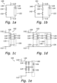
Figures 1a to 1e schematically illustrate various example embodiments of modules for use in an energy storage system, according to the present disclosure, -
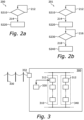
Figures 2a and 2b schematically illustrate flows of various example embodiments of methods of operating a module, according to the present disclosure, and -
Figure 3 schematically illustrates an example embodiment of an energy storage system according to the present disclosure. - In the drawings, like reference numerals will be used for like elements unless stated otherwise. Unless explicitly stated to the contrary, the drawings show only such elements that are necessary to illustrate the example embodiments, while other elements, in the interest of clarity, may be omitted or merely suggested. As illustrated in the figures, the sizes of elements and regions may be exaggerated for illustrative purposes and, thus, are provided to illustrate the general structures of the embodiments.
- With reference to
Figures 1a to 1e , the concept of a module according to the present disclosure will now be described in more detail. -
Figure 1a schematically illustrates an example embodiment of amodule 100 which may be included as part of an energy storage system (not shown). Themodule 100 includes afirst terminal 110 and asecond terminal 112. Theterminals - A
supercapacitor branch 120 is connected between thefirst terminal 110 and thesecond terminal 112 and includes anarrangement 122 including at least onesupercapacitor 124. In themodule 100, only asingle supercapacitor 124 is illustrated inFigure 1a , but it is envisaged that thearrangement 122 may include also more than one supercapacitor. If that is the case, thesupercapacitors 124 in thearrangement 122 in thesupercapacitor branch 120 may be connected in series and/or in parallel as needed to meet specific voltage and/or current supply requirements. - A
resistive bypass branch 130 is also connected between thefirst terminal 110 and thesecond terminal 112, i.e. in parallel with thesupercapacitor branch 120. Theresistive bypass branch 130 includes afirst bypass switch 132 and aresistance 134 which are connected in series as shown inFigure 1a . - As described earlier herein, if a fault (such as e.g. a short circuit) occurs within the
arrangement 122 ofsupercapacitors 124, a remaining energy within thearrangement 122 may be drained/burned via theresistance 134 by closing thefirst bypass switch 132. This procedure may continue at least until a remaining energy in thearrangement 122 is/goes below a certain threshold. -
Figure 1b schematically illustrates another example embodiment of amodule 101. In addition to the elements/components of themodule 100 described with reference toFigure 1a , themodule 101 further includes adirect bypass branch 140 connected between thefirst terminal 110 and thesecond terminal 112, and also in parallel with thesupercapacitor branch 120 and theresistive bypass branch 130. Thedirect bypass branch 140 includes asecond bypass switch 142. It is envisaged that thesecond bypass switch 142 may be closed once the remaining energy of thearrangement 122 has gone below the certain threshold (after draining/burning via theresistance 134 due to the closing of the first bypass switch 132), and thereby fully bypass themodule 100. By so doing, in case of a fault, the module may be bypassed such that it does not interfere with the functionality of e.g. other modules in the energy storage system (not shown) of which themodule 101 forms part. - With reference to
Figures 1a and 1b , it should be noted that a fault in thearrangement 122 of themodules arrangement 122 within thesupercapacitor branch 120. This is a result of the insight that the use ofsupercapacitors 124 instead of e.g. traditional rechargeable batteries as means for energy storage allows to not include such additional components (such as e.g. fuses) in the circuit. As described earlier herein, leaving out such additional components may allow for a less complex circuitry, with e.g. a lower footprint, and with e.g. a reduced cost of manufacturing. - In some embodiments of the
modules arrangement 122 within thesupercapacitor branch 120. In some embodiments, it is envisaged that there is at least no switch (or circuit breaker) connected in series with thearrangement 122 within thesupercapacitor branch 120. In some embodiments, it is envisaged that there is neither a fuse nor a switch (or circuit breaker) connected in series with thearrangement 122 within thesupercapacitor branch 120. Within all such embodiments, "something not in series with the arrangement" is to be interpreted as there being no such "something" between thearrangement 122 and any of thefirst terminal 110 and thesecond terminal 112. In some embodiments, thearrangement 122 of the one ormore supercapacitors 124 may therefore be connected directly between thefirst terminal 110 and thesecond terminal 112. Herein, "directly" of course includes there being e.g. connection wires, bus-bars or similar, but no additional electrical components such as resistors, switches, fuses, or similar. - Herein, a "bypass switch" is envisaged as being e.g. a disconnector, a circuit breaker or an electronic switch. As described earlier, such a bypass switch does not necessarily need to be able to break a larger current, in which case an electronic switch may be enough, reducing the need for more expensive and complex disconnectors and/or circuit breakers.
-
Figure 1c schematically illustrates a further example embodiment of a module 102 (wherein any branch other than thesupercapacitor branch 120 is not illustrated), which further includes anarray 150 ofdiodes 152. Eachdiode 152 is connected in reverse (with respect to polarity) across arespective supercapacitor 124. As described earlier herein, thediode array 150 may help to prevent damage to thesupercapacitors 124 due to a negative voltage which may appear during discharge of the supercapacitors 124 (via the resistance in the resistive bypass branch) during a fault. By connecting thediodes 152 in reverse across thesupercapacitors 124, the generated negative voltage during discharge may turn on thediodes 152 and prevent an amplitude of the negative voltage from increasing to more than a forward voltage of thediodes 152. -
Figures 1d and 1e schematically illustrate further example embodiments ofmodules module 103, thesupercapacitor branch 120 includes twosub-branches supercapacitors 124 connected in series. Each sub-branch 125 and 126 is further provided with arespective diode array diodes 152 connected in reverse across arespective supercapacitor 124. In themodule 104, thesupercapacitor branch 120 includes series-connected blocks of supercapacitors, wherein each block includes one or more parallel strings of series-connectedsupercapacitors 124. For each block, adiode 152 of thediode array 150 is connected in reverse across the block. Here, each diode is connected in reverse across more than a single supercapacitor. - It is also envisaged that, if there are no diodes included, the supercapacitor branch of a module as described herein may still be configured as in the
modules 103 and/or 104 (i.e. with two parallel sub-branches and/or with series connected blocks of parallel strings of series-connected supercapacitors). Other configurations of thesupercapacitor branch 120 are also envisaged, wherein thesupercapacitors 124 in thearrangement 122 are provided and connected in a way which meets required performance in e.g. terms of storage voltage and/or supply current. The idea of using at least a resistive bypass branch (and possibly also a direct bypass branch) applies to all such configurations of thesupercapacitor branch 120 described in the embodiments shown inFigs. 1c-1e . - A method of operating a module as described herein will now be described in more detail with reference to
Figures 2a and 2b . -
Figure 2a schematically illustrates a flow of an example embodiment of amethod 200. In a step S210, themethod 200 includes detecting whether a fault associated with one or more supercapacitors in the module has occurred. If it is determined that no fault has occurred, themethod 200 may continue to monitor the supercapacitors as indicated by thearrow 212. If, on the other hand, it is determined that a fault has occurred, themethod 200 may proceed as indicated by thearrow 214 to a further step S220. - Detecting the fault could for example be either from a supercapacitor cabinet/system, and may for example be based on current and/or voltage measurements, or e.g. by a battery management system (BMS) based on supercapacitor internal diagnostics. A voltage measurement may for example show a sudden decrease in voltage, which may indicate that e.g. a short circuit has occurred. Likewise, a current measurement may for example show a sudden increase in current, which may also indicate e.g. a short circuit fault. Whether a voltage is to be indicative of a fault may for example be figured out in accordance with specifications provided by a manufacturer of the supercapacitors, or similar. As described earlier herein, a fault is not necessarily required to be a short circuit fault. Other types of faults envisaged within the present disclosure include for example loss of BMS communication, supercapacitor over-temperatures, supercapacitor cabinet busbar over-temperatures, etc.
- The step S220 includes lowering a remaining energy in the (one or more) supercapacitors of the module by closing the first bypass switch within the resistive bypass branch. By so doing, the supercapacitors may be discharged through the resistance of the resistive bypass branch, and the fault may thereby be handled without negatively affecting other modules within a same energy storage system.
-
Figure 2b schematically illustrates a flow of another example embodiment of amethod 201. In themethod 201, an additional step S230 includes determining whether the remaining energy in the (one or more) supercapacitors is below a certain threshold. If the remaining energy is determined to still be higher than the certain threshold, themethod 201 may for example wait (as indicated by the arrow 216) until the threshold is reached. If it is determined that the remaining energy is below the certain threshold, themethod 201 may proceed (as indicated by the arrow 218) to a step S240, in which the supercapacitors are then directly bypassed by closing the second bypass switch within a direct bypass branch as described earlier herein. The module may then be fully bypassed, and current no longer required to flow through the resistance of the resistive bypass branch of the module. - An energy storage system according to the present disclosure will now be described with reference to
Figure 3 . -
Figure 3 schematically illustrates anenergy storage system 300, including aplurality 310 ofmodules 312 connected in series. Thesystem 300 also includes control means 320 (such as e.g. a computer implemented controller, or similar) for controlling at least one of themodules 312. Although not illustrated inFigure 3 , it is envisaged that the system also 300 includes means necessary for e.g. detecting whether a fault has occurred within amodule 312, and the control means 320 is thus such that themodule 312 may be controlled in accordance with a method as described herein, for example any one of themethods Figures 2a and 2b . In some embodiments, it is envisaged that the control means 320 may instead form part of amodule 312, and i.e. that eachmodule 312 may have its own internal control means 320. - The
system 300 may be connected e.g. to anelectrical power grid 330, in order to provide stabilization of theelectrical power grid 330 in times when e.g. a demand for power is high. As an example, during times when a demand for power is lower, the energy storage system may receive power from thegrid 330 in order to charge the supercapacitors in themodules 312. During times when the demand for power on thegrid 330 is higher, the increased demand may be compensated for by thesystem 300 instead providing power to thegrid 330 from the supercapacitors of themodules 312. If theelectrical power grid 330 is an AC power grid, the connection to theelectrical power grid 330 may be provided via an AC/DC conversion stage 332. Although not explicitly shown inFigure 3 , it is envisaged that such an AC/DC conversion stage 332 may, for control purposes, also be connected to the control means 320. - As illustrated in
Figure 3 , thesystem 300 may also include at least onefurther plurality 340 of series-connected modules (as e.g. described herein). Thefurther plurality 340 may be connected in series with theplurality 310. - In summary, the use of supercapacitors may enable a faster stabilization (due to the faster response time in terms of charging/discharging of the supercapacitors compared to e.g. traditional rechargeable batteries), and also an increased reliability as supercapacitors may handle an increased number of such charging/discharging cycles. The modules, control method therefor, as well as the energy storage system as described herein, provide an improved reliability in that a fault (e.g. a short circuit) within a module may be properly handled, and the module even completely bypassed, such that the operation of the other modules are not negatively affected by the occurrence of such a fault, and such that the system as a whole may still be available thereafter. As each module has its own means of handling a fault (the one or more bypass branches), fault handling may be distributed within the energy storage system. Additionally, if used, one or more diodes as described in here provides further protection against negative voltages.
- Although features and elements have been described above in particular combinations, each feature or element may be used alone without the other features and elements or in various combinations with or without other features and elements.
- Additionally, variations to the disclosed embodiments may be understood and effected by the skilled person in practicing the claimed invention, from a study of the drawings, the disclosure, and the appended claims. In the claims, the words "comprising" and "including" does not exclude other elements, and the indefinite article "a" or "an" does not exclude a plurality. The mere fact that certain features are recited in mutually different dependent claims does not indicate that a combination of these features cannot be used to advantage. However, the scope of protection is solely defined by the appended claims.
Claims (12)
- A module (100) for use in an energy storage system, including:a first terminal (110) and a second terminal (112);a supercapacitor branch (120) including an arrangement (122) of one or more supercapacitors (124), anda resistive bypass branch (130) including at least a first bypass switch (132) and a resistor (134) connected in series,wherein the supercapacitor branch and the resistive bypass branch are connected in parallel between the first terminal and the second terminal;further including a direct bypass branch (140) including at least a second bypass switch (142), wherein the direct bypass branch is also connected in parallel with the supercapacitor branch and the resistive bypass branch, between the first terminal and the second terminal;characterized in that the direct bypass branch (140) does not rely on or include a series connected resistor and in that the first bypass switch is configured to, upon an occurrence of a fault associated with the one or more supercapacitors, be closed such that the one or more supercapacitors are discharged through the resistor, thereby lowering a remaining energy in the one or more supercapacitors;wherein the second bypass switch is configured to subsequently be closed in order to directly bypass the one or more supercapacitors upon an occurrence of the remaining energy in the one or more supercapacitors being below a certain threshold.
- The module of claim 1, wherein there is no fuse connected in series with the arrangement of one or more supercapacitors and any one of the first terminal and the second terminal.
- The module of any one of claims 1 to 2, wherein there is no switch or circuit breaker connected in series with the arrangement of one or more supercapacitors and any one of the first terminal and the second terminal.
- The module of claim 1, wherein there is no fuse, switch or circuit breaker connected in series with the arrangement of one or more supercapacitors and any one of the first terminal and the second terminal.
- The module of any one of the preceding claims, wherein the arrangement of one or more supercapacitors are connected directly between the first terminal and the second terminal.
- The module (102, 103, 104) of any one of the preceding claims, further including an array (150) of diodes (152), wherein each diode (152) in said array of diodes is connected in reverse across at least one supercapacitor of said one or more supercapacitors.
- The module of any one of the preceding claims, wherein the arrangement of one or more supercapacitors includes two or more supercapacitors connected in series.
- The module of any one of the preceding claims, wherein the arrangement of one or more supercapacitors includes two or more supercapacitors connected in parallel.
- A method (200) of operating a module including a first terminal (110) and a second terminal (112), a supercapacitor branch (120) including an arrangement (122) of one or more supercapacitors (124), and a resistive bypass branch (130) including at least a first bypass switch (132) and a resistor (134) connected in series, wherein the supercapacitor branch and the resistive bypass branch are connected in parallel between the first terminal and the second terminal, wherein the module further includes a direct bypass branch (140) including at least a second bypass switch (142), wherein the direct bypass branch does not rely on or include a series connected resistor and is also connected in parallel with the supercapacitor branch and the resistive bypass branch, between the first terminal and the second terminal, the method including:a) detecting (S210) an occurrence of a fault associated with the one or more supercapacitors;b) lowering (S220) a remaining energy in the one or more supercapacitors by closing the first bypass switch, thereby discharging the one or more supercapacitors through the resistor;c-i) determining (S230) whether the remaining energy in the one or more supercapacitors is below a certain threshold, andc-ii) upon determining that the remaining energy is below the certain threshold, directly bypassing (S240) the one or more supercapacitors by closing the second bypass switch.
- The method of claim 9, wherein the fault is a short-circuit across at least one of the one or more supercapacitors.
- An energy storage system (300) including:a plurality (310) of modules (312) according to any one of claims 1 to 8 connected in series;a controller and/or supercapacitor internal diagnostics means configured to detect an occurrence of a fault associated with the one or more supercapacitors of at least one module of the plurality of modules;control means configured to, for the at least one module of the plurality of modules, close the first bypass switch, thereby discharging the one or more supercapacitors through the resistor, whereby a remaining energy in the one or more supercapacitors is lowered;means configured to, for the at least one module of the plurality of modules, determine whether the remaining energy in the one or more supercapacitors is below a certain threshold,the control means further configured to, for the at least one module of the plurality of modules, close the second bypass switch upon determining that the remaining energy is below the certain threshold, thereby directly bypassing the one or more supercapacitors.
- The energy storage system (301) of claim 11, further including at least a second plurality (340) of modules (312) according to any one of claims 1 to 8 connected in series, wherein the first plurality of modules and the at least a second plurality of modules are connected in parallel.
Applications Claiming Priority (1)
| Application Number | Priority Date | Filing Date | Title |
|---|---|---|---|
| PCT/EP2021/064573 WO2022253407A1 (en) | 2021-05-31 | 2021-05-31 | Module for large scale energy storage |
Publications (2)
| Publication Number | Publication Date |
|---|---|
| EP4348795A1 EP4348795A1 (en) | 2024-04-10 |
| EP4348795B1 true EP4348795B1 (en) | 2025-07-02 |
Family
ID=76325503
Family Applications (1)
| Application Number | Title | Priority Date | Filing Date |
|---|---|---|---|
| EP21730837.8A Active EP4348795B1 (en) | 2021-05-31 | 2021-05-31 | Module for large scale energy storage |
Country Status (5)
| Country | Link |
|---|---|
| US (1) | US12249856B2 (en) |
| EP (1) | EP4348795B1 (en) |
| JP (1) | JP7675217B2 (en) |
| CN (1) | CN117441278A (en) |
| WO (1) | WO2022253407A1 (en) |
Families Citing this family (3)
| Publication number | Priority date | Publication date | Assignee | Title |
|---|---|---|---|---|
| WO2024200298A1 (en) * | 2023-03-24 | 2024-10-03 | Hitachi Energy Ltd | Electrical protection circuit for energy storage unit |
| EP4525258A1 (en) * | 2023-09-13 | 2025-03-19 | Hitachi Energy Ltd | Coordinated triggering of module-level protection and bypass in energy storage systems |
| CN119297973B (en) * | 2024-09-10 | 2025-10-03 | 中国电建集团福建省电力勘测设计院有限公司 | A DC energy consumption device based on supercapacitor |
Citations (4)
| Publication number | Priority date | Publication date | Assignee | Title |
|---|---|---|---|---|
| US20090066291A1 (en) | 2007-09-10 | 2009-03-12 | Jenn-Yang Tien | Distributed energy storage control system |
| US20130009600A1 (en) | 2011-07-08 | 2013-01-10 | Samsung Electro-Mechanics Co., Ltd | Electric energy storage apparatus, voltage equalization module and voltage equalization method |
| WO2016044931A1 (en) | 2014-09-22 | 2016-03-31 | Polyvalor, Limited Partnership | Energy storage device and modular circuit |
| WO2020082660A1 (en) | 2018-10-22 | 2020-04-30 | 南京南瑞继保电气有限公司 | Direct current energy dissipation apparatus and control method therefor |
Family Cites Families (22)
| Publication number | Priority date | Publication date | Assignee | Title |
|---|---|---|---|---|
| JPH0799142A (en) | 1993-09-28 | 1995-04-11 | Okamura Kenkyusho:Kk | Power storage device |
| US5545933A (en) * | 1993-09-28 | 1996-08-13 | Okamura Laboratory Inc. | Electric power storage apparatus |
| US7471068B2 (en) | 2006-11-03 | 2008-12-30 | Ivus Industries, Llc | Ultra-fast ultracapacitor charging method and charger |
| CN201153087Y (en) | 2008-01-04 | 2008-11-19 | 西安交通大学 | A combination device of permanent magnet mechanism vacuum circuit breaker with series resistance |
| CN101217078B (en) | 2008-01-04 | 2011-06-01 | 西安交通大学 | A permanent magnetic actuator vacuum circuit breaker assembly with series resistance |
| DE102009025211A1 (en) | 2009-06-16 | 2010-01-28 | Daimler Ag | Battery cell arrangement for traction battery of battery and hybrid vehicles, has fuse element assigned to serial cells to disconnect cell in case of failure of other cells, where failed cell is separated by fuse element |
| CN103026572B (en) | 2010-07-23 | 2015-07-01 | Abb技术有限公司 | Method and arrangement for capacitor bank protection |
| KR101158214B1 (en) * | 2010-09-27 | 2012-06-19 | 삼성전기주식회사 | Device and method for stabilizing of voltage of energy storage |
| US10536007B2 (en) | 2011-03-05 | 2020-01-14 | Powin Energy Corporation | Battery energy storage system and control system and applications thereof |
| US9559529B1 (en) | 2011-07-28 | 2017-01-31 | The United States Of America As Represented By The Administrator Of National Aeronautics And Space Administration | Modular battery controller |
| DE112013006196T5 (en) | 2012-12-24 | 2015-09-10 | Magna Closures Inc. | Accident management system and method in an electronic lock of a motor vehicle locking device |
| US20150092311A1 (en) | 2013-09-30 | 2015-04-02 | Abb Technology Ag | Methods, systems, and computer readable media for protection of direct current building electrical systems |
| US9525290B2 (en) | 2013-10-25 | 2016-12-20 | Saft | Bypassable battery modules |
| WO2015195321A1 (en) | 2014-06-20 | 2015-12-23 | Ioxus, Inc. | Engine start and battery support module |
| CN105991054A (en) | 2015-03-06 | 2016-10-05 | 南京南瑞继保电气有限公司 | Converter sub module, control method and converter |
| US10050252B2 (en) | 2015-04-17 | 2018-08-14 | The Boeing Company | Fault tolerant battery cell bypass device and system |
| AU2015399888B2 (en) | 2015-06-22 | 2018-05-10 | Kabushiki Kaisha Toshiba | Storage cell system, storage cell module, and method for operating storage cell system |
| CN106229956A (en) | 2016-09-27 | 2016-12-14 | 上海北堃电力科技有限公司 | A kind of capacitor protection equipment and series compensation device |
| US11168663B2 (en) | 2017-06-22 | 2021-11-09 | General Electric Company | Blade pitch system including power source for wind turbine |
| CN108322056B (en) | 2018-03-23 | 2020-03-20 | 南京南瑞继保电气有限公司 | Modular high-voltage direct-current conversion device and control method thereof |
| CN109860741A (en) | 2019-02-27 | 2019-06-07 | 广州宝狮新能源有限公司 | A kind of compatible fault-tolerant large-sized battery series connection and PCS parallel system |
| KR102127888B1 (en) | 2019-10-08 | 2020-06-29 | 주식회사 엠알티 | power short-circuit switch application Energy storage system |
-
2021
- 2021-05-31 WO PCT/EP2021/064573 patent/WO2022253407A1/en not_active Ceased
- 2021-05-31 US US18/565,973 patent/US12249856B2/en active Active
- 2021-05-31 CN CN202180098900.2A patent/CN117441278A/en active Pending
- 2021-05-31 JP JP2023573624A patent/JP7675217B2/en active Active
- 2021-05-31 EP EP21730837.8A patent/EP4348795B1/en active Active
Patent Citations (4)
| Publication number | Priority date | Publication date | Assignee | Title |
|---|---|---|---|---|
| US20090066291A1 (en) | 2007-09-10 | 2009-03-12 | Jenn-Yang Tien | Distributed energy storage control system |
| US20130009600A1 (en) | 2011-07-08 | 2013-01-10 | Samsung Electro-Mechanics Co., Ltd | Electric energy storage apparatus, voltage equalization module and voltage equalization method |
| WO2016044931A1 (en) | 2014-09-22 | 2016-03-31 | Polyvalor, Limited Partnership | Energy storage device and modular circuit |
| WO2020082660A1 (en) | 2018-10-22 | 2020-04-30 | 南京南瑞继保电气有限公司 | Direct current energy dissipation apparatus and control method therefor |
Non-Patent Citations (1)
| Title |
|---|
| MARIN S. HALPER, JAMES C. ELLENBOGEN: "Supercapacitors: A Brief Overview", TECHNICAL REVIEW, MITRE, MCLEAN, VIRGINIA, USA, 1 March 2006 (2006-03-01), McLean, Virginia, USA, pages 1 - 40, XP009566260 |
Also Published As
| Publication number | Publication date |
|---|---|
| JP2024519185A (en) | 2024-05-08 |
| US20240266847A1 (en) | 2024-08-08 |
| EP4348795A1 (en) | 2024-04-10 |
| WO2022253407A1 (en) | 2022-12-08 |
| JP7675217B2 (en) | 2025-05-12 |
| US12249856B2 (en) | 2025-03-11 |
| CN117441278A (en) | 2024-01-23 |
Similar Documents
| Publication | Publication Date | Title |
|---|---|---|
| EP4348795B1 (en) | Module for large scale energy storage | |
| CN103733381A (en) | Secure battery element | |
| KR20140035799A (en) | Battery system, and energy storage system | |
| JP2012122856A (en) | Battery pack device | |
| JP6811019B2 (en) | Rechargeable battery system | |
| US10367187B2 (en) | Storage battery including a disconnector having a fuse and an explosive with a heat bridge providing continuity of service in the event of a malfunction | |
| CN211830332U (en) | Auxiliary power supply device for improving availability of storage battery pack | |
| US6741437B2 (en) | Safety device for electrical storage cell battery and battery equipped with the device | |
| JP4057193B2 (en) | Abnormality detection method when using batteries in parallel | |
| JP2016134962A (en) | Power storage system | |
| KR102848533B1 (en) | Apparatus for detecting battery states and battery protection apparatus | |
| JP6155854B2 (en) | Battery system | |
| CN113904307A (en) | Direct current bus capacitor buffer protection circuit and method | |
| JP2002159135A (en) | Protective circuit for electric double-layer capacitor module | |
| CN216312666U (en) | Direct current bus capacitor buffer protection circuit | |
| CN111342548A (en) | Auxiliary power supply device for improving usability of storage battery pack | |
| JP2018011447A (en) | Large-capacity storage battery system | |
| US20250141244A1 (en) | Discharge resistor arrangement for energy storage cabinets in an energy storage system | |
| JP2011160639A (en) | Instantaneous voltage drop countermeasure apparatus | |
| KR20250177387A (en) | An energy storage circuit with bypass functionality for a high-voltage dc energy management system | |
| JP5962558B2 (en) | Battery monitoring device | |
| EP4607744A1 (en) | Energy storage system and method for operating a protection circuit in an energy storage system | |
| EP4415206A1 (en) | An energy storage segment for an energy storage system and a method for controlling an energy storage system | |
| US20250260245A1 (en) | Battery string pre-charge operation | |
| KR20260033134A (en) | Battery system including power supply and operating method thereof |
Legal Events
| Date | Code | Title | Description |
|---|---|---|---|
| STAA | Information on the status of an ep patent application or granted ep patent |
Free format text: STATUS: UNKNOWN |
|
| STAA | Information on the status of an ep patent application or granted ep patent |
Free format text: STATUS: THE INTERNATIONAL PUBLICATION HAS BEEN MADE |
|
| PUAI | Public reference made under article 153(3) epc to a published international application that has entered the european phase |
Free format text: ORIGINAL CODE: 0009012 |
|
| STAA | Information on the status of an ep patent application or granted ep patent |
Free format text: STATUS: REQUEST FOR EXAMINATION WAS MADE |
|
| 17P | Request for examination filed |
Effective date: 20231102 |
|
| AK | Designated contracting states |
Kind code of ref document: A1 Designated state(s): AL AT BE BG CH CY CZ DE DK EE ES FI FR GB GR HR HU IE IS IT LI LT LU LV MC MK MT NL NO PL PT RO RS SE SI SK SM TR |
|
| DAV | Request for validation of the european patent (deleted) | ||
| DAX | Request for extension of the european patent (deleted) | ||
| RIN1 | Information on inventor provided before grant (corrected) |
Inventor name: SOONG, THEODORE Inventor name: WU, TONG Inventor name: BAI, HAOFENG Inventor name: MENG, LEXUAN Inventor name: SVENSSON, JAN Inventor name: INGESTROEM, GUNNAR Inventor name: STEINKE, JUERGEN Inventor name: HASLER, JEAN-PHILIPPE |
|
| GRAP | Despatch of communication of intention to grant a patent |
Free format text: ORIGINAL CODE: EPIDOSNIGR1 |
|
| STAA | Information on the status of an ep patent application or granted ep patent |
Free format text: STATUS: GRANT OF PATENT IS INTENDED |
|
| INTG | Intention to grant announced |
Effective date: 20250121 |
|
| GRAS | Grant fee paid |
Free format text: ORIGINAL CODE: EPIDOSNIGR3 |
|
| P01 | Opt-out of the competence of the unified patent court (upc) registered |
Free format text: CASE NUMBER: APP_17847/2025 Effective date: 20250411 |
|
| GRAA | (expected) grant |
Free format text: ORIGINAL CODE: 0009210 |
|
| STAA | Information on the status of an ep patent application or granted ep patent |
Free format text: STATUS: THE PATENT HAS BEEN GRANTED |
|
| RIN1 | Information on inventor provided before grant (corrected) |
Inventor name: SOONG, THEODORE Inventor name: WU, TONG Inventor name: BAI, HAOFENG Inventor name: MENG, LEXUAN Inventor name: SVENSSON, JAN Inventor name: INGESTROEM, GUNNAR Inventor name: STEINKE, JUERGEN Inventor name: HASLER, JEAN-PHILIPPE |
|
| AK | Designated contracting states |
Kind code of ref document: B1 Designated state(s): AL AT BE BG CH CY CZ DE DK EE ES FI FR GB GR HR HU IE IS IT LI LT LU LV MC MK MT NL NO PL PT RO RS SE SI SK SM TR |
|
| REG | Reference to a national code |
Ref country code: GB Ref legal event code: FG4D |
|
| REG | Reference to a national code |
Ref country code: CH Ref legal event code: EP |
|
| REG | Reference to a national code |
Ref country code: DE Ref legal event code: R096 Ref document number: 602021033366 Country of ref document: DE |
|
| REG | Reference to a national code |
Ref country code: IE Ref legal event code: FG4D |
|
| REG | Reference to a national code |
Ref country code: NL Ref legal event code: MP Effective date: 20250702 |
|
| PG25 | Lapsed in a contracting state [announced via postgrant information from national office to epo] |
Ref country code: PT Free format text: LAPSE BECAUSE OF FAILURE TO SUBMIT A TRANSLATION OF THE DESCRIPTION OR TO PAY THE FEE WITHIN THE PRESCRIBED TIME-LIMIT Effective date: 20251103 |
|
| PG25 | Lapsed in a contracting state [announced via postgrant information from national office to epo] |
Ref country code: NL Free format text: LAPSE BECAUSE OF FAILURE TO SUBMIT A TRANSLATION OF THE DESCRIPTION OR TO PAY THE FEE WITHIN THE PRESCRIBED TIME-LIMIT Effective date: 20250702 |
|
| REG | Reference to a national code |
Ref country code: AT Ref legal event code: MK05 Ref document number: 1810391 Country of ref document: AT Kind code of ref document: T Effective date: 20250702 |
|
| PG25 | Lapsed in a contracting state [announced via postgrant information from national office to epo] |
Ref country code: IS Free format text: LAPSE BECAUSE OF FAILURE TO SUBMIT A TRANSLATION OF THE DESCRIPTION OR TO PAY THE FEE WITHIN THE PRESCRIBED TIME-LIMIT Effective date: 20251102 |
|
| PG25 | Lapsed in a contracting state [announced via postgrant information from national office to epo] |
Ref country code: NO Free format text: LAPSE BECAUSE OF FAILURE TO SUBMIT A TRANSLATION OF THE DESCRIPTION OR TO PAY THE FEE WITHIN THE PRESCRIBED TIME-LIMIT Effective date: 20251002 |
|
| REG | Reference to a national code |
Ref country code: LT Ref legal event code: MG9D |
|
| PG25 | Lapsed in a contracting state [announced via postgrant information from national office to epo] |
Ref country code: AT Free format text: LAPSE BECAUSE OF FAILURE TO SUBMIT A TRANSLATION OF THE DESCRIPTION OR TO PAY THE FEE WITHIN THE PRESCRIBED TIME-LIMIT Effective date: 20250702 |
|
| PG25 | Lapsed in a contracting state [announced via postgrant information from national office to epo] |
Ref country code: FI Free format text: LAPSE BECAUSE OF FAILURE TO SUBMIT A TRANSLATION OF THE DESCRIPTION OR TO PAY THE FEE WITHIN THE PRESCRIBED TIME-LIMIT Effective date: 20250702 |
|
| PG25 | Lapsed in a contracting state [announced via postgrant information from national office to epo] |
Ref country code: HR Free format text: LAPSE BECAUSE OF FAILURE TO SUBMIT A TRANSLATION OF THE DESCRIPTION OR TO PAY THE FEE WITHIN THE PRESCRIBED TIME-LIMIT Effective date: 20250702 |
|
| PG25 | Lapsed in a contracting state [announced via postgrant information from national office to epo] |
Ref country code: GR Free format text: LAPSE BECAUSE OF FAILURE TO SUBMIT A TRANSLATION OF THE DESCRIPTION OR TO PAY THE FEE WITHIN THE PRESCRIBED TIME-LIMIT Effective date: 20251003 |
|
| PG25 | Lapsed in a contracting state [announced via postgrant information from national office to epo] |
Ref country code: CZ Free format text: LAPSE BECAUSE OF FAILURE TO SUBMIT A TRANSLATION OF THE DESCRIPTION OR TO PAY THE FEE WITHIN THE PRESCRIBED TIME-LIMIT Effective date: 20250702 Ref country code: SE Free format text: LAPSE BECAUSE OF FAILURE TO SUBMIT A TRANSLATION OF THE DESCRIPTION OR TO PAY THE FEE WITHIN THE PRESCRIBED TIME-LIMIT Effective date: 20250702 |
|
| PG25 | Lapsed in a contracting state [announced via postgrant information from national office to epo] |
Ref country code: LV Free format text: LAPSE BECAUSE OF FAILURE TO SUBMIT A TRANSLATION OF THE DESCRIPTION OR TO PAY THE FEE WITHIN THE PRESCRIBED TIME-LIMIT Effective date: 20250702 |
|
| PG25 | Lapsed in a contracting state [announced via postgrant information from national office to epo] |
Ref country code: PL Free format text: LAPSE BECAUSE OF FAILURE TO SUBMIT A TRANSLATION OF THE DESCRIPTION OR TO PAY THE FEE WITHIN THE PRESCRIBED TIME-LIMIT Effective date: 20250702 Ref country code: BG Free format text: LAPSE BECAUSE OF FAILURE TO SUBMIT A TRANSLATION OF THE DESCRIPTION OR TO PAY THE FEE WITHIN THE PRESCRIBED TIME-LIMIT Effective date: 20250702 |
|
| PG25 | Lapsed in a contracting state [announced via postgrant information from national office to epo] |
Ref country code: RS Free format text: LAPSE BECAUSE OF FAILURE TO SUBMIT A TRANSLATION OF THE DESCRIPTION OR TO PAY THE FEE WITHIN THE PRESCRIBED TIME-LIMIT Effective date: 20251002 |
|
| PG25 | Lapsed in a contracting state [announced via postgrant information from national office to epo] |
Ref country code: ES Free format text: LAPSE BECAUSE OF FAILURE TO SUBMIT A TRANSLATION OF THE DESCRIPTION OR TO PAY THE FEE WITHIN THE PRESCRIBED TIME-LIMIT Effective date: 20250702 |
|
| REG | Reference to a national code |
Ref country code: DE Ref legal event code: R026 Ref document number: 602021033366 Country of ref document: DE |
|
| PLBI | Opposition filed |
Free format text: ORIGINAL CODE: 0009260 |
|
| PG25 | Lapsed in a contracting state [announced via postgrant information from national office to epo] |
Ref country code: SM Free format text: LAPSE BECAUSE OF FAILURE TO SUBMIT A TRANSLATION OF THE DESCRIPTION OR TO PAY THE FEE WITHIN THE PRESCRIBED TIME-LIMIT Effective date: 20250702 |
|
| REG | Reference to a national code |
Ref country code: CH Ref legal event code: L11 Free format text: ST27 STATUS EVENT CODE: U-0-0-L10-L11 (AS PROVIDED BY THE NATIONAL OFFICE) Effective date: 20260409 |
|
| PLAB | Opposition data, opponent's data or that of the opponent's representative modified |
Free format text: ORIGINAL CODE: 0009299OPPO |
|
| PG25 | Lapsed in a contracting state [announced via postgrant information from national office to epo] |
Ref country code: DK Free format text: LAPSE BECAUSE OF FAILURE TO SUBMIT A TRANSLATION OF THE DESCRIPTION OR TO PAY THE FEE WITHIN THE PRESCRIBED TIME-LIMIT Effective date: 20250702 |
|
| PG25 | Lapsed in a contracting state [announced via postgrant information from national office to epo] |
Ref country code: IT Free format text: LAPSE BECAUSE OF FAILURE TO SUBMIT A TRANSLATION OF THE DESCRIPTION OR TO PAY THE FEE WITHIN THE PRESCRIBED TIME-LIMIT Effective date: 20250702 |
|
| REG | Reference to a national code |
Ref country code: CH Ref legal event code: L10 Free format text: ST27 STATUS EVENT CODE: U-0-0-L10-L00 (AS PROVIDED BY THE NATIONAL OFFICE) Effective date: 20260416 |
|
| PLAX | Notice of opposition and request to file observation + time limit sent |
Free format text: ORIGINAL CODE: EPIDOSNOBS2 |
|
| PG25 | Lapsed in a contracting state [announced via postgrant information from national office to epo] |
Ref country code: SK Free format text: LAPSE BECAUSE OF FAILURE TO SUBMIT A TRANSLATION OF THE DESCRIPTION OR TO PAY THE FEE WITHIN THE PRESCRIBED TIME-LIMIT Effective date: 20250702 Ref country code: EE Free format text: LAPSE BECAUSE OF FAILURE TO SUBMIT A TRANSLATION OF THE DESCRIPTION OR TO PAY THE FEE WITHIN THE PRESCRIBED TIME-LIMIT Effective date: 20250702 |