EP4348595B1 - Verfahren zum trainieren eines neuronalen netzes - Google Patents
Verfahren zum trainieren eines neuronalen netzes Download PDFInfo
- Publication number
- EP4348595B1 EP4348595B1 EP22728308.2A EP22728308A EP4348595B1 EP 4348595 B1 EP4348595 B1 EP 4348595B1 EP 22728308 A EP22728308 A EP 22728308A EP 4348595 B1 EP4348595 B1 EP 4348595B1
- Authority
- EP
- European Patent Office
- Prior art keywords
- camera
- image
- images
- neural network
- pixels
- Prior art date
- Legal status (The legal status is an assumption and is not a legal conclusion. Google has not performed a legal analysis and makes no representation as to the accuracy of the status listed.)
- Active
Links
Images
Classifications
-
- G—PHYSICS
- G06—COMPUTING OR CALCULATING; COUNTING
- G06V—IMAGE OR VIDEO RECOGNITION OR UNDERSTANDING
- G06V10/00—Arrangements for image or video recognition or understanding
- G06V10/20—Image preprocessing
- G06V10/24—Aligning, centring, orientation detection or correction of the image
-
- G—PHYSICS
- G06—COMPUTING OR CALCULATING; COUNTING
- G06V—IMAGE OR VIDEO RECOGNITION OR UNDERSTANDING
- G06V10/00—Arrangements for image or video recognition or understanding
- G06V10/70—Arrangements for image or video recognition or understanding using pattern recognition or machine learning
- G06V10/77—Processing image or video features in feature spaces; using data integration or data reduction, e.g. principal component analysis [PCA] or independent component analysis [ICA] or self-organising maps [SOM]; Blind source separation
- G06V10/774—Generating sets of training patterns; Bootstrap methods, e.g. bagging or boosting
-
- G—PHYSICS
- G06—COMPUTING OR CALCULATING; COUNTING
- G06T—IMAGE DATA PROCESSING OR GENERATION, IN GENERAL
- G06T7/00—Image analysis
- G06T7/30—Determination of transform parameters for the alignment of images, i.e. image registration
- G06T7/33—Determination of transform parameters for the alignment of images, i.e. image registration using feature-based methods
- G06T7/337—Determination of transform parameters for the alignment of images, i.e. image registration using feature-based methods involving reference images or patches
-
- G—PHYSICS
- G06—COMPUTING OR CALCULATING; COUNTING
- G06V—IMAGE OR VIDEO RECOGNITION OR UNDERSTANDING
- G06V10/00—Arrangements for image or video recognition or understanding
- G06V10/10—Image acquisition
- G06V10/12—Details of acquisition arrangements; Constructional details thereof
- G06V10/14—Optical characteristics of the device performing the acquisition or on the illumination arrangements
-
- G—PHYSICS
- G06—COMPUTING OR CALCULATING; COUNTING
- G06V—IMAGE OR VIDEO RECOGNITION OR UNDERSTANDING
- G06V10/00—Arrangements for image or video recognition or understanding
- G06V10/20—Image preprocessing
- G06V10/28—Quantising the image, e.g. histogram thresholding for discrimination between background and foreground patterns
-
- G—PHYSICS
- G06—COMPUTING OR CALCULATING; COUNTING
- G06V—IMAGE OR VIDEO RECOGNITION OR UNDERSTANDING
- G06V10/00—Arrangements for image or video recognition or understanding
- G06V10/20—Image preprocessing
- G06V10/32—Normalisation of the pattern dimensions
-
- G—PHYSICS
- G06—COMPUTING OR CALCULATING; COUNTING
- G06V—IMAGE OR VIDEO RECOGNITION OR UNDERSTANDING
- G06V10/00—Arrangements for image or video recognition or understanding
- G06V10/70—Arrangements for image or video recognition or understanding using pattern recognition or machine learning
- G06V10/82—Arrangements for image or video recognition or understanding using pattern recognition or machine learning using neural networks
-
- G—PHYSICS
- G06—COMPUTING OR CALCULATING; COUNTING
- G06V—IMAGE OR VIDEO RECOGNITION OR UNDERSTANDING
- G06V20/00—Scenes; Scene-specific elements
- G06V20/50—Context or environment of the image
- G06V20/56—Context or environment of the image exterior to a vehicle by using sensors mounted on the vehicle
-
- G—PHYSICS
- G06—COMPUTING OR CALCULATING; COUNTING
- G06T—IMAGE DATA PROCESSING OR GENERATION, IN GENERAL
- G06T2207/00—Indexing scheme for image analysis or image enhancement
- G06T2207/20—Special algorithmic details
- G06T2207/20081—Training; Learning
-
- G—PHYSICS
- G06—COMPUTING OR CALCULATING; COUNTING
- G06T—IMAGE DATA PROCESSING OR GENERATION, IN GENERAL
- G06T2207/00—Indexing scheme for image analysis or image enhancement
- G06T2207/20—Special algorithmic details
- G06T2207/20084—Artificial neural networks [ANN]
-
- G—PHYSICS
- G06—COMPUTING OR CALCULATING; COUNTING
- G06T—IMAGE DATA PROCESSING OR GENERATION, IN GENERAL
- G06T2207/00—Indexing scheme for image analysis or image enhancement
- G06T2207/20—Special algorithmic details
- G06T2207/20112—Image segmentation details
- G06T2207/20132—Image cropping
-
- G—PHYSICS
- G06—COMPUTING OR CALCULATING; COUNTING
- G06T—IMAGE DATA PROCESSING OR GENERATION, IN GENERAL
- G06T2207/00—Indexing scheme for image analysis or image enhancement
- G06T2207/30—Subject of image; Context of image processing
- G06T2207/30248—Vehicle exterior or interior
- G06T2207/30252—Vehicle exterior; Vicinity of vehicle
Definitions
- the present invention relates to a method for training a neural network.
- the present invention further relates to a method for training a neural network for recognizing an object in an image, to a method for detecting an object in an image using a neural network, and to a method for detecting an object in an image.
- the abovementioned problem is not limited to inconsistencies in color information.
- using cameras that differ in at least one property among the group of properties consisting of maximum pixel resolution, color gamut, use of color or polarization filters, camera manufacturer, camera model, and exposure settings, and the like may also result in the problem that a neural network trained using images obtained with the first camera may display degraded performance when operating on images obtained with the second camera.
- US2018342044 A1 discloses a resolution enhancement technique.
- An apparatus receives first image data at a first resolution, and second image data at a resolution less than the first resolution.
- the second image data may be scaled to the first resolution and compared to the first image data.
- Application of a neural network may scale the first image data to a resolution higher than the first resolution.
- the application of the neural network may incorporate signals based on the scaled second image data.
- the signals may include information obtained by comparing the scaled second image data to the resolution of the first image data.
- US 2020/372282 A1 discloses a system and method for adapting images from different cameras so that a single trained classifier or an analyzer may be used.
- the classifier or analyzer operates on images that include a particular color distribution or characteristic.
- a generative network is used to adapt images from other cameras to have a similar color distribution or characteristic for use by the classifier or analyzer.
- a generative adversarial process is used to train the generative network.
- KR 102242939 B1 provides a camera device that can more efficiently generate high-resolution images.
- the camera device comprises an image sensor generating first Bayer data having a first resolution, and a processor outputting second Bayer data having a second resolution higher than the first resolution by performing deep learning based on the first Bayer data.
- US 2017/185851 A1 discloses a system that includes one or more processors, and a memory including instructions, which when executed by the one or more processors, cause the one or more processors to perform a method.
- the method includes receiving first image data from a first image sensor mounted on a vehicle and second image data from a second image sensor mounted on the vehicle, the vehicle including an element configured to open into a space external to the vehicle.
- the method further includes generating a depth map from a comparison of the first image data and the second image data, the depth map including an object. In accordance with a determination that the object, in the depth map, is within the space into which the element is configured to open, it is determined that the object will interfere with opening of the element into the space. Furthermore, in accordance with a determination that the object, in the depth map, is not within the space into which the element is configured to open, it is determined that the object will not interfere with opening of the element into the space.
- this object is achieved using a method for training a neural network for image transformation, comprising providing a vehicle, such as a car, on which are mounted a first camera and a second camera.
- the first camera and the second camera each have a same orientation relative to the vehicle and are arranged spaced apart in a default moving direction of the vehicle.
- the default moving direction corresponds to a direction in which the steering wheel is in an unturned position.
- the first camera and the second camera are different from each other with respect to at least one property among the group of properties consisting of maximum pixel resolution, color gamut, use of color or polarization filters, camera manufacturer, camera model, and exposure settings.
- the first and second cameras are assumed to have identical properties when these cameras are from the same series and have the same model number. Put differently, process variations that are inevitable when manufacturing multiple cameras that are supposed to be identical, are not taken into account although the invention could be applied to those cameras as well.
- the method according to the present invention further comprises allowing or controlling the vehicle to move along a trajectory.
- This trajectory may correspond to a predefined route through a given area.
- Such trajectories are often used when recording images for applications such as Google ® Street View ® .
- a recording operation is repeatedly performed for obtaining a dataset comprising a plurality of pairs of images, wherein each recording operation comprises triggering the first camera and the second camera at different time instants such that at a time or recording an image, the entrance pupil of the first camera and the entrance pupil of the second camera are at substantially the same position along the trajectory.
- Each pair of images comprises an image recorded by the first camera and an image recorded by the second camera during a given recording operation.
- triggering of that camera among the first camera and second camera of which the entrance pupil reaches said same position the latest is delayed by an amount that is equal to the distance d between the first camera and second camera in the default moving direction divided by the velocity v of the vehicle relative to the triggering of the other camera among the first camera and second camera.
- the triggering should be performed such that a difference between the positions of the entrance pupils at the times of recording the respective images is as small as possible. This particularly holds for a difference in position in a direction perpendicular to the optical axis of the first and second camera as this difference is strongly related to parallax phenomena.
- the obtained dataset is used for training a neural network, such as a convolutional neural network, to learn an image transformation for transforming an image of a scene recorded by the first camera into an image that mimics an image of the scene as it would have been recorded by the second camera.
- a neural network such as a convolutional neural network
- a large variety of different scenes may be imaged.
- Such large variety greatly improves the accuracy of the neural network. Recording the large variety is made possible by the combination of the mounting of the cameras, i.e. both cameras face the same direction for recording the same scene, and the particular triggering of these cameras, i.e. both cameras record an image from substantially the same position in space despite the vehicle being moving.
- the method may further comprise upscaling a pixel resolution of images recorded by the first camera if these images have a lower pixel resolution than the images recorded by the second camera.
- the pixel resolution of images recorded by the second camera may be downscaled if these images have a higher pixel resolution than the images recorded by the first camera.
- Such upscaling or downscaling may be performed before using the dataset for training the neural network.
- the method may further comprise performing an image registration for each pair of images in the dataset for geometrically aligning pixels in the image recorded by the first camera and pixels in the image recorded by the second camera.
- performing the image registration may comprise, for each pair of images, selecting one image in the pair of images as a source image and selecting the other image in the pair of images as a target image, determining a geometrical transformation for mapping the source image onto the target image using at least one of an intensity pattern comparison and an image feature comparison, and applying the determined geometrical transformation to the source image for obtaining a transformed source image.
- the geometrical transformation may be determined by comparing the position of corresponding features in the images. For example, the position of a feature, such as a particular shape, color, or the like, may be determined in the source image and in the target image. The geometrical transformation should ensure that the position of corresponding features in the first and second images should be substantially identical. Instead of feature based comparison, the intensity patterns of the first and second image could be compared.
- the method may further comprise determining at least one region in the transformed source image comprising pixels for which no corresponding pixels are present in the target image, and cropping and/or cutting the transformed source image to exclude the determined at least one region.
- the method may additionally comprise determining at least one region in the target image comprising pixels for which no corresponding pixels are present in the transformed source image, and cropping and/or cutting the target image to exclude the determined at least one region.
- the target image and the source image in the dataset can be replaced by the cropped/cut target image and the cropped/cut transformed source image, respectively.
- the method may further comprise upscaling or downscaling the cropped/cut target image and the cropped/cut transformed source image to a pixel resolution of the original source image or target image.
- the method may further comprise determining at least one region in the transformed source image comprising pixels for which no corresponding pixels are present in the target image, and constructing a binary mask for the transformed source image.
- the binary mask comprises at least one region indicating pixels in the transformed source image that have corresponding pixels in the target image, and comprises at least one region indicating pixels in the transformed source image that have no corresponding pixels in the target image.
- the method may further comprise determining at least one region in the target image comprising pixels for which no corresponding pixels are present in the transformed source image, and constructing a binary mask for the target image.
- the binary mask comprises at least one region indicating pixels in the target image that have corresponding pixels in the transformed source image, and comprises at least one region indicating pixels in the target image that have no corresponding pixels in the transformed source image.
- using the obtained dataset for training a neural network may comprise using the binary mask of the target image and the binary mask of the transformed source image to determine pixels in the target image and the transformed source image that are ignored when training the neural network.
- the training of the neural network may comprise determining in the transformed source image of each pair of images provided to the neural network, pixels for which corresponding pixels exist in the target image of that pair of images, and when training the neural network, taking into account only those pixels in the transformed source images for which corresponding pixels have been found in the corresponding target images.
- the second camera may be a lower resolution camera and the first camera a higher resolution camera, wherein images recorded by the first camera suffer from a parasitic light sensitivity problem and/or purple fringing.
- Parasitic Light Sensitivity is a performance parameter, particularly for CMOS Image Sensors, which quantifies the sensor sensitivity to light when the shutter is supposedly closed.
- Purple fringing refers to an unfocused purple or magenta ghost image appearing in an image. Both these effects are more pronounced in high resolution cameras.
- the method according to the present invention allows these effects to be mitigated by appropriately training the neural network to perform a transformation on the images obtained with the first camera.
- the dataset used for this training comprises high resolution images obtained using the first camera, which images display the abovementioned effects, and low resolution images obtained using the second camera, in which images the abovementioned effects are not present or at least to a lesser extent.
- the neural network is then trained to identify an image transformation that can be used on the images obtained by the first camera to remove the abovementioned effects.
- the high resolution images of the first camera may be downscaled prior to using these images in the training of the neural network.
- the neural network is trained to either apply a virtual polarization filter to the images recorded by the first camera, or to remove the effects of the virtual polarization filter from images recorded by the second camera.
- the present invention provides a method for training a further neural network for recognizing an object, comprising using the method as described above for training a neural network to transform an image.
- the method further comprises providing a further dataset comprising a plurality of images recorded by the first camera and/or one or more cameras substantially identical to the first camera, transforming the images of the further dataset using the trained neural network, and training a further neural network for recognizing objects in an image recorded by the second camera or a camera substantially identical to the second camera using the transformed images of the further dataset.
- a further neural network is used for recognizing an object in an image.
- This further neural network has been trained using images recorded by the first camera and/or one or more cameras substantially identical to the first camera.
- the further neural network will display degraded performance when it is used for recognizing an object in an image recorded by the second camera or a camera substantially identical to the second camera.
- the present invention addresses this problem by training a neural network to learn an image transformation for transforming an image of a scene recorded by the first camera into an image that mimics an image of the scene as it would have been recorded by the second camera, and to use this neural network to transform the further dataset that comprises images recorded by the first camera and/or one or more cameras substantially identical to the first camera.
- This transformed further dataset can then be used to train the further neural network.
- the further neural network trained in this manner will display improved performance when recognizing an object in an image recorded by the second camera or a camera substantially identical to the second camera.
- the present invention provides a method for detecting an object in a first image, comprising using the method described above for training a neural network to transform an image.
- the method further comprises providing a further neural network for recognizing an object, wherein the further neural network has been trained using a dataset of images recorded by the second camera and/or by one or more cameras that are substantially identical to the second camera.
- the method comprises recording a first image using the first camera or a camera that is substantially identical to the first camera, transforming the first image using the trained neural network, and recognizing the object in the transformed first image using the trained further neural network.
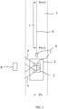
- First camera 1 is directed to the left of vehicle 3 and has a first field-of-view 4.
- second camera 2 is also directed to the left of vehicle 3 and has a second field-of-view 5 which may or may not differ from field-of-view 4 at a time of recording an image.
- Vehicle 3 moves along a trajectory 6 on a road 7. Along this trajectory, several positions Pn, Pn+1, Pn+2 are identified at which first camera 1 and second camera 2 are supposed to record an image.
- vehicle 1 may be equipped with a known positioning system that marks when first camera 1 reaches a particular position, e.g. Pn + 1.
- first camera 1 may be triggered to record an image when vehicle 3 has traversed a given distance s relative to a position at which first camera 1 recorded a previous image.
- the accuracy of the position Pn + 1 is much less important than ensuring that first camera 1 and second camera 2 record an image at substantially the same position in space.
- First camera 1 and second camera 2 are different cameras. More in particular, first camera 1 and second camera 2 are different from each other with respect to at least one property among the group of properties consisting of maximum pixel resolution, color gamut, use of color or polarization filters, camera manufacturer, camera model, and exposure settings.
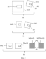
- Figure 2 illustrates several steps for constructing a dataset to be used for training a neural network in accordance with the present invention.
- the dataset comprises a plurality of pairs 11 of images.
- a single pair 11 is indicated comprising an image Im1 recorded by first camera 1 and an image Im2 recorded by second camera 2.
- image Im1 has a lower pixel resolution than image Im2.
- a region 10 can be identified that corresponds to an object, e.g. object 8, in figure 1 .
- image Im1 and image Im2 may be geometrically misaligned.
- images Im1, Im2 may have a mutual rotation and/or translation.
- the relative position and rotation of region 10 in each of the images is different.
- a difference in pixel resolution of images Im1, Im2 may be reduced by upscaling or downscaling.
- image Im2 has been downscaled using known methods.
- image Im1 is subjected to a geometrical transformation for geometrically aligning images Im1, Im2.
- This transformed image is indicated by T(Im1).
- T(Im1) the position of region 10 in these images may not be exactly the same.
- binary masks can be generated that can be used when training the neural network.
- a binary mask M(Im2) can be generated for target image Im2.
- This binary mask has one or more regions m+ that comprise pixels that each have a respective corresponding pixel in transformed source image T(Im1).
- binary mask M(Im2) has one or more regions m- that comprise pixels that each do not have a respective corresponding pixel in transformed source image T(Im1).
- a binary mask M(T(Im1)) can be generated for transformed source image T(Im1).
- This binary mask has one or more regions m+ that comprise pixels that each have a respective corresponding pixel in target image Im2.
- binary mask M(T(Im1)) has one or more regions m- that comprise pixels that each do not have a respective corresponding pixel in target image T(Im2).
- binary masks M(T(Im1)) and M(Im2) can be used for determining which pixels to take or not to take into account.
- the transformed source image (T(Im1)) and the target image (Im2) may be cropped and/or cut to exclude regions in these images in which pixels have no corresponding pixels in the other image.
- the source and target images in the dataset may be replaced by the cropped/cut counterparts.
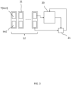
- Figure 3 illustrates the training of a neural network 20 using a dataset 12 constructed in figure 2 in accordance with the present invention.
- Figure 3 illustrates an example in which dataset 12 comprises a plurality of pairs 11 of images. Each pair 11 comprises an image T(Im1), and an image Im2 as discussed in connection in figure 3 .
- Dataset 12 is fed to a neural network 20 to train this network. More in particular, neural network 20 is trained such that images T(Im1) are transformed to mimic images Im2. To this end, a comparison is used, here indicated as being executed by a comparator 21, between images T(Im1) transformed by neural network 20 and the corresponding images Im2. The result of this comparison is used for training neural network 20. Comparator 21 can be embodied using a loss function for providing neural network feedback.
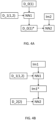
- Figures 4A and 4B illustrate two different methods for recognizing an object in an image in accordance with the present invention.
- Figure 4A illustrates recognition of an object in an image Im2 recorded by the second camera 2 or a camera substantial identical to second camera 2 by a neural network NN2.
- This latter neural network is trained, as indicated by the dashed line, using a data set D_0(1)*.
- first camera 1 may correspond to a well known and widely used camera
- second camera 2 may correspond to a novel camera having a higher resolution, different color gamut, etc.
- the present invention proposes to use vehicle 1, on which a first camera 1 and second camera 2 are mounted, for recording a dataset D_1(1,2) that comprises a plurality of pairs of images, each pair of images comprising an image recorded by first camera 1, and an image recorded by second camera 2.
- This dataset may be modified as shown in figure 3 .
- this dataset is used for training neural network NN1.
- modified dataset D_0(1)* After having trained neural network NN1, it is used for transforming images in dataset D_0(1) into a modified dataset D_0(1)*. This latter dataset mimics a dataset of images that would have been obtained using second camera 2. Furthermore, modified dataset D_0(1)* is used for training neural network NN2. Because it appears that the images of modified dataset D_0(1)* and image Im2 are recorded using the same or substantial identical camera, the performance of neural network NN2 for recognizing an object in an image recorded by second camera 2 or a camera substantially identical to second camera 2 is improved.
- Figure 4B illustrates an example wherein neural network NN2 for recognizing an object in an image is trained using a dataset D_2(2).
- This dataset comprises images that are recorded using second camera 2 and/or one or more cameras substantial identical to second camera 2.
- Neural network NN2 is less suitable for recognizing an object in an image recorded by first camera 1.
- the present invention proposes to use vehicle 1, on which a first camera 1 and second camera 2 are mounted, for recording a dataset D_1(1,2) that comprises a plurality of pairs of images, each pair of images comprising an image recorded by first camera 1, and an image recorded by second camera 2.
- This dataset is used for training neural network NN1.
- This latter network is then used for transforming image Im1, recorded by first camera 1 or a camera substantially identical to first camera 1, into a modified image Im1*.
- This modified image is then fed to neural network NN2 for recognizing an object therein.
- the trained neutral network NN1 can be used for transforming images that suffer from unwanted effects.
- first camera 1 may correspond to a low resolution camera
- second camera 2 may correspond to a high resolution camera that however suffers from a parasitic light sensitivity problem and/or purple fringing.
- neural network NN1 is trained such that an inputted image obtained by second camera 2 is transformed into an image that mimics an image that would have been obtained by first camera 1.
- neural network NN1 is configured for removing the effects of purple fringing and/or the parasitic light sensitivity from an image obtained by second camera 2.
- the images obtained by first camera 1 may be up-scaled to the pixel resolution of the images obtained by second camera 2.
- a problem may occur with reflecting windows, sun reflection, etc. These problems can be mitigated by using a polarization filter.
- having a polarization filter on a camera reduces the light intake, which may not be practical given the shutter times in combination with moving vehicle 3.
- This problem can be addressed by the present invention by using a second camera 2 and a first camera 1 that do and do not have a polarization filter, respectively. It is noted that second camera 2 and first camera 1 may be identical apart from whether the polarization filter is used.
- neural network NN1 is trained to transform an image obtained using first camera 1 or a camera substantially identical to first camera 1 without polarization filter, to an image that mimics the image that would have been obtained by this camera if the polarization filter would have been used.
- a similar approach can be used when using color filters.
Landscapes
- Engineering & Computer Science (AREA)
- Theoretical Computer Science (AREA)
- General Physics & Mathematics (AREA)
- Physics & Mathematics (AREA)
- Multimedia (AREA)
- Evolutionary Computation (AREA)
- Computer Vision & Pattern Recognition (AREA)
- Health & Medical Sciences (AREA)
- Artificial Intelligence (AREA)
- Computing Systems (AREA)
- Databases & Information Systems (AREA)
- General Health & Medical Sciences (AREA)
- Medical Informatics (AREA)
- Software Systems (AREA)
- Image Analysis (AREA)
Claims (15)
- Verfahren zum Trainieren eines neuronalen Netzes (20) zur Bildtransformation, umfassend:Bereitstellen eines Fahrzeugs, wie eines Autos (3), an dem eine erste Kamera (1) und eine zweite Kamera (2) montiert sind, wobei die erste Kamera (1) und die zweite Kamera (2) jeweils die gleiche Ausrichtung relativ zum Fahrzeug (3) aufweisen und in einer Standardbewegungsrichtung (9) des Fahrzeugs (3) um einen Abstand d voneinander beabstandet angeordnet sind, wobei sich die erste Kamera (1) und die zweite Kamera (2) hinsichtlich mindestens einer Eigenschaft aus der Gruppe von Eigenschaften bestehend aus maximaler Pixelauflösung, Farbpalette, Verwendung von Farb- oder Polarisationsfiltern, Kamerahersteller, Kameramodell und Belichtungseinstellungen voneinander unterscheiden;Ermöglichen oder Steuern der Bewegung des Fahrzeugs (3) entlang einer Trajektorie (6);während der Bewegung entlang der Trajektorie (6) wiederholtes Durchführen eines Aufzeichnungsvorgangs zum Erhalten eines Datensatzes (11), der eine Vielzahl von Bildpaaren (11) umfasst, wobei jeder Aufzeichnungsvorgang das Auslösen der ersten Kamera (1) und der zweiten Kamera (2) zu unterschiedlichen Zeitpunkten umfasst, so dass sich zu einem Zeitpunkt der Aufzeichnung eines Bildes die Eintrittspupille der ersten Kamera (1) und die Eintrittspupille der zweiten Kamera (2) an im Wesentlichen derselben Position (Pn, Pn+1, Pn+2) entlang der Trajektorie (6) befinden, wobei jedes Bildpaar (11) ein von der ersten Kamera (1) aufgezeichnetes Bild (Im1) und ein von der zweiten Kamera (2) aufgezeichnetes Bild (Im2) während eines gegebenen Aufzeichnungsvorgangs umfasst;wobei zum Zwecke des Aufzeichnens eines Bildes durch die erste Kamera (1) und die zweite Kamera (2), so dass sich die Eintrittspupillen dieser Kameras zum Zeitpunkt der Aufzeichnung der jeweiligen Bilder im Wesentlichen an der gleichen Position befinden, Auslösen der Kamera von der ersten Kamera (1) und der zweiten Kamera (2), deren Eintrittspupille diese gleiche Position zuletzt erreicht, um einen Betrag verzögert wird, der gleich dem Abstand d zwischen der ersten Kamera (1) und der zweiten Kamera (2) in der Standardbewegungsrichtung (9) geteilt durch die Geschwindigkeit v des Fahrzeugs (3) relativ zum Auslösen der anderen Kamera von der ersten Kamera (1) und der zweiten Kamera (2) ist;Verwenden des erhaltenen Datensatzes zum Trainieren eines neuronalen Netzes (20), um eine Bildtransformation zum Transformieren eines Bildes einer von der ersten Kamera (1) aufgezeichneten Szene in ein Bild zu erlernen, das ein Bild der Szene nachahmt, wie es von der zweiten Kamera (2) aufgezeichnet worden wäre.
- Verfahren nach Anspruch 1, ferner umfassend das Aufwärtsskalieren der Pixelauflösung von Bildern (Im1), die von der ersten Kamera (1) aufgezeichnet wurden, wenn diese Bilder (Im1) eine niedrigere Pixelauflösung aufweisen als die Bilder (Im2), die von der zweiten Kamera (2) aufgezeichnet wurden, oder das Abwärtsskalieren der Pixelauflösung von Bildern (Im2), die von der zweiten Kamera (2) aufgezeichnet wurden, wenn diese Bilder (Im2) eine höhere Pixelauflösung aufweisen als die Bilder (Im1), die von der ersten Kamera (1) aufgezeichnet wurden.
- Verfahren nach Anspruch 1 oder 2, umfassend ferner das Durchführen einer Bildregistrierung für jedes Bildpaar (11) im Datensatz (12) zum geometrischen Ausrichten von Pixeln im von der ersten Kamera (1) aufgezeichneten Bild (Im1) und Pixeln im von der zweiten Kamera (2) aufgezeichneten Bild (Im2) vor dem Verwenden des Datensatzes zum Trainieren des neuronalen Netzes (20).
- Verfahren nach Anspruch 3, wobei das Durchführen der Bildregistrierung für jedes Bildpaar (11) umfasst:
Auswählen eines Bildes (Im1) im Bildpaar (11) als Quellbild, und Auswählen des anderen Bildes (Im2) im Bildpaar (11) als Zielbild:Bestimmen einer geometrischen Transformation zum Abbilden des Quellbildes (Im1) auf das Zielbild (Im2) unter Verwendung von mindestens einem Intensitätsmustervergleich und einem Bildmerkmalvergleich;Anwenden der bestimmten geometrischen Transformation auf das Quellbild (Im1), um ein transformiertes Quellbild (T(Im1)) zu erhalten. - Verfahren nach Anspruch 4, ferner umfassend:Bestimmen von mindestens einem Bereich im transformierten Quellbild (T(Im1)), der Pixel umfasst, für die im Zielbild (Im2) keine entsprechenden Pixel vorhanden sind, und Zuschneiden und/oder Ausschneiden des transformierten Quellbilds (T(Im1)), um den bestimmten mindestens einen Bereich auszuschließen;Bestimmen von mindestens einem Bereich im Zielbild (Im2), der Pixel umfasst, für die im transformierten Quellbild (T(Im1)) keine entsprechenden Pixel vorhanden sind, und Zuschneiden und/oder Ausschneiden des Zielbildes (Im2), um den bestimmten mindestens einen Bereich auszuschließen; undErsetzen des Zielbildes (Im2) durch das zugeschnittene/ausgeschnittene Zielbild, und Ersetzen des Quellbildes (Im2) durch das zugeschnittene/ausgeschnittene transformierte Quellbild (T(Im1)).
- Verfahren nach Anspruch 5, ferner umfassend das Aufwärtsskalieren oder Abwärtsskalieren des zugeschnittenen/ausgeschnittenen Zielbildes (Im2) und des zugeschnittenen/ausgeschnittenen transformierten Quellbildes (T(Im1)) auf eine Pixelauflösung des ursprünglichen Quellbildes (Im1) oder Zielbildes (Im2).
- Verfahren nach Anspruch 4, ferner umfassend:Bestimmen von mindestens einem Bereich im transformierten Quellbild (T(Im1)), der Pixel umfasst, für die im Zielbild (Im2) keine entsprechenden Pixel vorhanden sind, und Erstellen einer binären Maske (M(T(Im1))) für das transformierte Quellbild (T(Im1)), wobei die binäre Maske (M(T(Im1))) mindestens einen Bereich (m+) umfasst, der Pixel im transformierten Quellbild (T(Im1)) anzeigt, die im Zielbild (Im2) entsprechende Pixel aufweisen, und mindestens einen Bereich (m-) umfasst, der Pixel im transformierten Quellbild (T(Im1)) anzeigt, die im Zielbild (Im2) keine entsprechenden Pixel aufweisen;Bestimmen von mindestens einem Bereich im Zielbild (Im2), der Pixel umfasst, für die im transformierten Quellbild (T(Im1)) keine entsprechenden Pixel vorhanden sind, und Erstellen einer binären Maske (M(Im2)) für das Zielbild (Im2), wobei die binäre Maske (M(Im2)) mindestens einen Bereich (m+) umfasst, der Pixel im Zielbild (Im2) anzeigt, die entsprechende Pixel im transformierten Quellbild (T(Im1)) aufweisen, und mindestens einen Bereich (m-) umfasst, der Pixel im Zielbild (Im2) anzeigt, die keine entsprechenden Pixel im transformierten Quellbild (T(Im1)) aufweisen.
- Verfahren nach Anspruch 7, wobei das Verwenden des erhaltenen Datensatzes zum Trainieren eines neuronalen Netzes (20) das Verwenden der binären Maske (M(Im2)) des Zielbildes (Im2) und der binären Maske (M(T(Im1))) des transformierten Quellbildes (T(Im1)) umfasst, um Pixel im Zielbild (Im2) und im transformierten Quellbild (T(Im1)) zu bestimmen, die beim Trainieren des neuronalen Netzes (20) ignoriert werden.
- Verfahren nach Anspruch 4, wobei das Training des neuronalen Netzes (20) umfasst:Bestimmen von Pixeln im transformierten Quellbild (T(Im1)) jedes dem neuronalen Netz (20) bereitgestellten Bildpaares (11), für die entsprechende Pixel im Zielbild (Im2) dieses Bildpaares (11) vorhanden sind; undbeim Trainieren des neuronalen Netzes (20) Berücksichtigen nur der Pixel in den transformierten Quellbildern (T(Im1)), für die entsprechende Pixel in den entsprechenden Zielbildern (Im2) gefunden wurden.
- Verfahren nach einem der vorstehenden Ansprüche, wobei die zweite Kamera (2) eine Kamera mit niedrigerer Auflösung ist und die erste Kamera (1) eine Kamera mit höherer Auflösung ist, wobei die von der ersten Kamera (1) aufgezeichneten Bilder unter einem Problem der parasitären Lichtempfindlichkeit und/oder eines violetten Farbsaums leiden.
- Verfahren nach einem der vorstehenden Ansprüche, wobei die zweite Kamera (2) beim Aufzeichnen von Bildern einen Polarisationsfilter verwendet.
- Verfahren nach einem der vorstehenden Ansprüche, ferner umfassend:
Aufzeichnen eines ersten Bildes mit der ersten Kamera (1) oder einer mit der ersten Kamera im Wesentlichen identischen Kamera, und Transformieren des ersten Bildes unter Verwendung des trainierten neuronalen Netzes (20). - Verfahren zum Trainieren eines weiteren neuronalen Netzes (NN2) zum Erkennen eines Objekts, umfassend:Verwenden des Verfahrens nach einem der vorstehenden Ansprüche zum Trainieren eines neuronalen Netzes (NN1) zum Transformieren eines Bildes;Bereitstellen eines weiteren Datensatzes (D_0(1)), der eine Vielzahl von Bildern umfasst, die von der ersten Kamera (1) und/oder einer oder mehreren Kameras, die mit der ersten Kamera (1) im Wesentlichen identisch sind, aufgezeichnet wurden;Transformieren der Bilder des weiteren Datensatzes (D_0(1)) unter Verwendung des trainierten neuronalen Netzes (NN1);Trainieren eines weiteren neuronalen Netzes (NN2) zum Erkennen von Objekten in einem von der zweiten Kamera (2) oder einer mit der zweiten Kamera (2) im Wesentlichen identischen Kamera aufgezeichneten Bild (Im2) unter Verwendung der transformierten Bilder des weiteren Datensatzes D_0(1)*.
- Verfahren zum Erkennen eines Objekts in einem zweiten Bild unter Verwendung eines weiteren neuronalen Netzes (NN2), umfassend:Trainieren des weiteren neuronalen Netzes (NN2) gemäß Anspruch 13;Aufzeichnen eines zweiten Bildes (Im2) durch die zweite Kamera (2) oder eine mit der zweiten Kamera (2) im Wesentlichen identische Kamera;Erkennen des Objekts im zweiten Bild (Im2) unter Verwendung des trainierten weiteren neuronalen Netzes (NN2).
- Verfahren zum Erkennen eines Objekts in einem ersten Bild (Im1), umfassend:Verwenden des Verfahrens nach einem der Ansprüche 1 bis 12 zum Trainieren eines neuronalen Netzes (NN1) zum Transformieren eines Bildes;Bereitstellen eines weiteren neuronalen Netzes (NN2) zum Erkennen eines Objekts, das unter Verwendung eines Datensatzes (D_2(2)) von von der zweiten Kamera (2) und/oder von einer oder mehreren mit der zweiten Kamera (2) im Wesentlichen identischen Kameras aufgezeichneten Bildern trainiert wurde;Aufzeichnen eines ersten Bildes (Im1) unter Verwendung der ersten Kamera (1);Transformieren des ersten Bildes (Im1) unter Verwendung des trainierten neuronalen Netzes (NN1);Erkennen des Objekts im transformierten ersten Bild (Im1*) unter Verwendung des trainierten weiteren neuronalen Netzes (NN2).
Applications Claiming Priority (2)
| Application Number | Priority Date | Filing Date | Title |
|---|---|---|---|
| NL2028357A NL2028357B1 (en) | 2021-06-01 | 2021-06-01 | Method for training a neural network |
| PCT/NL2022/050297 WO2022255866A1 (en) | 2021-06-01 | 2022-05-31 | Method for training a neural network |
Publications (3)
| Publication Number | Publication Date |
|---|---|
| EP4348595A1 EP4348595A1 (de) | 2024-04-10 |
| EP4348595B1 true EP4348595B1 (de) | 2024-07-24 |
| EP4348595C0 EP4348595C0 (de) | 2024-07-24 |
Family
ID=77711363
Family Applications (1)
| Application Number | Title | Priority Date | Filing Date |
|---|---|---|---|
| EP22728308.2A Active EP4348595B1 (de) | 2021-06-01 | 2022-05-31 | Verfahren zum trainieren eines neuronalen netzes |
Country Status (8)
| Country | Link |
|---|---|
| US (1) | US20240371139A1 (de) |
| EP (1) | EP4348595B1 (de) |
| CA (1) | CA3220235A1 (de) |
| ES (1) | ES2989174T3 (de) |
| HU (1) | HUE067740T2 (de) |
| NL (1) | NL2028357B1 (de) |
| PL (1) | PL4348595T3 (de) |
| WO (1) | WO2022255866A1 (de) |
Family Cites Families (24)
| Publication number | Priority date | Publication date | Assignee | Title |
|---|---|---|---|---|
| US6930593B2 (en) * | 2003-02-24 | 2005-08-16 | Iteris, Inc. | Lane tracking system employing redundant image sensing devices |
| US7577292B2 (en) * | 2005-12-30 | 2009-08-18 | Microsoft Corporation | Automatic removal of purple fringing from images |
| SI1903534T1 (sl) * | 2006-09-22 | 2009-04-30 | Cyclomedia Technology B V | Metoda in sistem za izdelavo panoramske slike z vozila med voĺ˝njo |
| US8493436B2 (en) * | 2008-02-08 | 2013-07-23 | Google Inc. | Panoramic camera with multiple image sensors using timed shutters |
| JP6532023B2 (ja) * | 2015-10-28 | 2019-06-19 | 本田技研工業株式会社 | 車載機器制御システム |
| US10776636B2 (en) * | 2015-12-29 | 2020-09-15 | Faraday&Future Inc. | Stereo camera-based detection of objects proximate to a vehicle |
| US11892311B2 (en) * | 2016-11-26 | 2024-02-06 | Thinkware Corporation | Image processing apparatus, image processing method, computer program and computer readable recording medium |
| GB2559760B (en) * | 2017-02-16 | 2019-08-28 | Jaguar Land Rover Ltd | Apparatus and method for displaying information |
| US10438322B2 (en) * | 2017-05-26 | 2019-10-08 | Microsoft Technology Licensing, Llc | Image resolution enhancement |
| US10768628B2 (en) * | 2017-12-12 | 2020-09-08 | Uatc, Llc | Systems and methods for object detection at various ranges using multiple range imagery |
| EP3710977A1 (de) * | 2017-12-21 | 2020-09-23 | Siemens Aktiengesellschaft | Farbanpassung unter verwendung von gegensätzlichen trainingsnetzwerken |
| US10691968B2 (en) * | 2018-02-08 | 2020-06-23 | Genetec Inc. | Systems and methods for locating a retroreflective object in a digital image |
| US11966838B2 (en) * | 2018-06-19 | 2024-04-23 | Nvidia Corporation | Behavior-guided path planning in autonomous machine applications |
| US10733761B2 (en) * | 2018-06-29 | 2020-08-04 | Zoox, Inc. | Sensor calibration |
| US10832062B1 (en) * | 2018-09-28 | 2020-11-10 | Zoox, Inc. | Image embedding for object tracking |
| KR102788816B1 (ko) * | 2018-11-08 | 2025-03-31 | 삼성전자주식회사 | 전자 장치 및 그 제어 방법 |
| DE112020002604T5 (de) * | 2019-05-29 | 2022-03-03 | Mobileye Vision Technologies Ltd. | Systeme und verfahren für die fahrzeugnavigation |
| KR102242939B1 (ko) * | 2019-06-13 | 2021-04-21 | 엘지이노텍 주식회사 | 카메라 장치 및 카메라 장치의 이미지 생성 방법 |
| DE102019208735B4 (de) * | 2019-06-14 | 2021-12-23 | Volkswagen Aktiengesellschaft | Verfahren zum Betreiben eines Fahrassistenzsystems eines Fahrzeugs und Fahrerassistenzsystem für ein Fahrzeug |
| CN111492416A (zh) * | 2020-02-12 | 2020-08-04 | 深圳市锐明技术股份有限公司 | 一种违章监控系统及违章监控方法 |
| US11321862B2 (en) * | 2020-09-15 | 2022-05-03 | Toyota Research Institute, Inc. | Systems and methods for multi-camera modeling with neural camera networks |
| US11538185B2 (en) * | 2020-12-11 | 2022-12-27 | Zoox, Inc. | Localization based on semantic objects |
| US12169949B2 (en) * | 2020-12-23 | 2024-12-17 | Lyft, Inc. | Camera to camera calibration |
| DE102021106988A1 (de) * | 2021-03-22 | 2022-09-22 | Conti Temic Microelectronic Gmbh | Verfahren und System zur Bestimmung von Eigenbewegungsinformationen eines Fahrzeugs |
-
2021
- 2021-06-01 NL NL2028357A patent/NL2028357B1/en active
-
2022
- 2022-05-31 WO PCT/NL2022/050297 patent/WO2022255866A1/en not_active Ceased
- 2022-05-31 HU HUE22728308A patent/HUE067740T2/hu unknown
- 2022-05-31 CA CA3220235A patent/CA3220235A1/en active Pending
- 2022-05-31 US US18/565,322 patent/US20240371139A1/en active Pending
- 2022-05-31 EP EP22728308.2A patent/EP4348595B1/de active Active
- 2022-05-31 ES ES22728308T patent/ES2989174T3/es active Active
- 2022-05-31 PL PL22728308.2T patent/PL4348595T3/pl unknown
Also Published As
| Publication number | Publication date |
|---|---|
| US20240371139A1 (en) | 2024-11-07 |
| WO2022255866A1 (en) | 2022-12-08 |
| ES2989174T3 (es) | 2024-11-25 |
| CA3220235A1 (en) | 2022-12-08 |
| HUE067740T2 (hu) | 2024-11-28 |
| PL4348595T3 (pl) | 2024-09-30 |
| EP4348595A1 (de) | 2024-04-10 |
| EP4348595C0 (de) | 2024-07-24 |
| NL2028357B1 (en) | 2022-12-13 |
Similar Documents
| Publication | Publication Date | Title |
|---|---|---|
| Ye et al. | Universal semantic segmentation for fisheye urban driving images | |
| US20190375261A1 (en) | Method and device for determining a trajectory in off-road scenarios | |
| CN114785960B (zh) | 一种基于无线传输技术的360度全景行车记录仪系统 | |
| DE102009050505A1 (de) | Detektion eines freien Pfads durch Strassenmodellerstellung | |
| CN116403186B (zh) | 基于FPN Swin Transformer与Pointnet++的自动驾驶三维目标检测方法 | |
| JP4872890B2 (ja) | 画像の歪曲補正方法 | |
| JP7667962B2 (ja) | 情報処理装置、情報処理システム、情報処理方法、及び情報処理プログラム | |
| CN111797810B (zh) | 一种行车过程中驾驶员前视预瞄区域的获取方法 | |
| CN114905512A (zh) | 一种智能巡检机器人全景追踪及避障方法及系统 | |
| DE102018100909A1 (de) | Verfahren zum Rekonstruieren von Bildern einer Szene, die durch ein multifokales Kamerasystem aufgenommen werden | |
| CN112950698A (zh) | 基于双目散焦图像的深度估计方法、装置、介质和设备 | |
| DE102020109997A1 (de) | System und Verfahren, um zuverlässige gestitchte Bilder zu machen | |
| DE102019131565A1 (de) | Bildverarbeitungsvorrichtung und bildverarbeitungsverfahren | |
| EP4348595B1 (de) | Verfahren zum trainieren eines neuronalen netzes | |
| CN115761659A (zh) | 识别模型构建方法、车型识别方法、电子设备及存储介质 | |
| CN119478890A (zh) | 基于机器视觉的全景环视辅助驾驶方法及系统 | |
| CN113705403B (zh) | 一种与全景成像系统融合的前方目标车辆碰撞预警方法 | |
| JP7327911B2 (ja) | 画像処理装置、画像処理方法、及びプログラム | |
| CN114926331A (zh) | 一种应用于车辆的全景图像拼接方法 | |
| CN116309885B (zh) | 一种基于视觉里程计的车载摄像头在线标定方法 | |
| EP1724726A1 (de) | Verfahren und Vorrichtung zur Parkraumvermessung mittels einer Monokamera | |
| Kian et al. | Cross-Camera Module Training of Raw Sensor Data-Based Automotive Machine Vision: Challenges and Solutions | |
| DE102024207234B3 (de) | Verfahren zum Betrieb wenigstens einer Kamera eines Fahrzeugs, Kamerasystem, Computerprogramm, Datenträger und Fahrzeug | |
| CN119904498B (zh) | 一种面向夜间场景融合异源图像的深度估计方法及装置 | |
| Babuchowska et al. | Camera systems–key technology for ADAS in autonomous vehicles |
Legal Events
| Date | Code | Title | Description |
|---|---|---|---|
| STAA | Information on the status of an ep patent application or granted ep patent |
Free format text: STATUS: UNKNOWN |
|
| STAA | Information on the status of an ep patent application or granted ep patent |
Free format text: STATUS: THE INTERNATIONAL PUBLICATION HAS BEEN MADE |
|
| PUAI | Public reference made under article 153(3) epc to a published international application that has entered the european phase |
Free format text: ORIGINAL CODE: 0009012 |
|
| STAA | Information on the status of an ep patent application or granted ep patent |
Free format text: STATUS: REQUEST FOR EXAMINATION WAS MADE |
|
| 17P | Request for examination filed |
Effective date: 20231221 |
|
| AK | Designated contracting states |
Kind code of ref document: A1 Designated state(s): AL AT BE BG CH CY CZ DE DK EE ES FI FR GB GR HR HU IE IS IT LI LT LU LV MC MK MT NL NO PL PT RO RS SE SI SK SM TR |
|
| GRAP | Despatch of communication of intention to grant a patent |
Free format text: ORIGINAL CODE: EPIDOSNIGR1 |
|
| STAA | Information on the status of an ep patent application or granted ep patent |
Free format text: STATUS: GRANT OF PATENT IS INTENDED |
|
| INTG | Intention to grant announced |
Effective date: 20240416 |
|
| GRAS | Grant fee paid |
Free format text: ORIGINAL CODE: EPIDOSNIGR3 |
|
| GRAA | (expected) grant |
Free format text: ORIGINAL CODE: 0009210 |
|
| STAA | Information on the status of an ep patent application or granted ep patent |
Free format text: STATUS: THE PATENT HAS BEEN GRANTED |
|
| AK | Designated contracting states |
Kind code of ref document: B1 Designated state(s): AL AT BE BG CH CY CZ DE DK EE ES FI FR GB GR HR HU IE IS IT LI LT LU LV MC MK MT NL NO PL PT RO RS SE SI SK SM TR |
|
| DAV | Request for validation of the european patent (deleted) | ||
| DAX | Request for extension of the european patent (deleted) | ||
| REG | Reference to a national code |
Ref country code: GB Ref legal event code: FG4D |
|
| REG | Reference to a national code |
Ref country code: CH Ref legal event code: EP |
|
| REG | Reference to a national code |
Ref country code: DE Ref legal event code: R096 Ref document number: 602022004852 Country of ref document: DE |
|
| REG | Reference to a national code |
Ref country code: IE Ref legal event code: FG4D |
|
| U01 | Request for unitary effect filed |
Effective date: 20240729 |
|
| U07 | Unitary effect registered |
Designated state(s): AT BE BG DE DK EE FI FR IT LT LU LV MT NL PT RO SE SI Effective date: 20240902 |
|
| REG | Reference to a national code |
Ref country code: GR Ref legal event code: EP Ref document number: 20240401861 Country of ref document: GR Effective date: 20241007 |
|
| REG | Reference to a national code |
Ref country code: ES Ref legal event code: FG2A Ref document number: 2989174 Country of ref document: ES Kind code of ref document: T3 Effective date: 20241125 |
|
| REG | Reference to a national code |
Ref country code: HU Ref legal event code: AG4A Ref document number: E067740 Country of ref document: HU |
|
| PG25 | Lapsed in a contracting state [announced via postgrant information from national office to epo] |
Ref country code: IS Free format text: LAPSE BECAUSE OF FAILURE TO SUBMIT A TRANSLATION OF THE DESCRIPTION OR TO PAY THE FEE WITHIN THE PRESCRIBED TIME-LIMIT Effective date: 20241124 |
|
| PG25 | Lapsed in a contracting state [announced via postgrant information from national office to epo] |
Ref country code: HR Free format text: LAPSE BECAUSE OF FAILURE TO SUBMIT A TRANSLATION OF THE DESCRIPTION OR TO PAY THE FEE WITHIN THE PRESCRIBED TIME-LIMIT Effective date: 20240724 |
|
| PG25 | Lapsed in a contracting state [announced via postgrant information from national office to epo] |
Ref country code: RS Free format text: LAPSE BECAUSE OF FAILURE TO SUBMIT A TRANSLATION OF THE DESCRIPTION OR TO PAY THE FEE WITHIN THE PRESCRIBED TIME-LIMIT Effective date: 20241024 |
|
| PG25 | Lapsed in a contracting state [announced via postgrant information from national office to epo] |
Ref country code: RS Free format text: LAPSE BECAUSE OF FAILURE TO SUBMIT A TRANSLATION OF THE DESCRIPTION OR TO PAY THE FEE WITHIN THE PRESCRIBED TIME-LIMIT Effective date: 20241024 Ref country code: IS Free format text: LAPSE BECAUSE OF FAILURE TO SUBMIT A TRANSLATION OF THE DESCRIPTION OR TO PAY THE FEE WITHIN THE PRESCRIBED TIME-LIMIT Effective date: 20241124 Ref country code: HR Free format text: LAPSE BECAUSE OF FAILURE TO SUBMIT A TRANSLATION OF THE DESCRIPTION OR TO PAY THE FEE WITHIN THE PRESCRIBED TIME-LIMIT Effective date: 20240724 |
|
| PG25 | Lapsed in a contracting state [announced via postgrant information from national office to epo] |
Ref country code: SM Free format text: LAPSE BECAUSE OF FAILURE TO SUBMIT A TRANSLATION OF THE DESCRIPTION OR TO PAY THE FEE WITHIN THE PRESCRIBED TIME-LIMIT Effective date: 20240724 |
|
| PG25 | Lapsed in a contracting state [announced via postgrant information from national office to epo] |
Ref country code: SK Free format text: LAPSE BECAUSE OF FAILURE TO SUBMIT A TRANSLATION OF THE DESCRIPTION OR TO PAY THE FEE WITHIN THE PRESCRIBED TIME-LIMIT Effective date: 20240724 |
|
| PLBE | No opposition filed within time limit |
Free format text: ORIGINAL CODE: 0009261 |
|
| STAA | Information on the status of an ep patent application or granted ep patent |
Free format text: STATUS: NO OPPOSITION FILED WITHIN TIME LIMIT |
|
| 26N | No opposition filed |
Effective date: 20250425 |
|
| U20 | Renewal fee for the european patent with unitary effect paid |
Year of fee payment: 4 Effective date: 20250527 |
|
| PGFP | Annual fee paid to national office [announced via postgrant information from national office to epo] |
Ref country code: PL Payment date: 20250503 Year of fee payment: 4 |
|
| PGFP | Annual fee paid to national office [announced via postgrant information from national office to epo] |
Ref country code: ES Payment date: 20250602 Year of fee payment: 4 |
|
| PGFP | Annual fee paid to national office [announced via postgrant information from national office to epo] |
Ref country code: HU Payment date: 20250515 Year of fee payment: 4 Ref country code: NO Payment date: 20250530 Year of fee payment: 4 |
|
| PGFP | Annual fee paid to national office [announced via postgrant information from national office to epo] |
Ref country code: GR Payment date: 20250528 Year of fee payment: 4 |
|
| PGFP | Annual fee paid to national office [announced via postgrant information from national office to epo] |
Ref country code: CH Payment date: 20250601 Year of fee payment: 4 |
|
| PGFP | Annual fee paid to national office [announced via postgrant information from national office to epo] |
Ref country code: TR Payment date: 20250515 Year of fee payment: 4 |
|
| PGFP | Annual fee paid to national office [announced via postgrant information from national office to epo] |
Ref country code: CZ Payment date: 20250507 Year of fee payment: 4 |
|
| PGFP | Annual fee paid to national office [announced via postgrant information from national office to epo] |
Ref country code: IE Payment date: 20250527 Year of fee payment: 4 |