EP4348167B1 - Verfahren und systeme zur dreidimensionalen bildgebung eines transparenten biologischen objekts in einer biologischen probe mittels optischer vollfeldtomografie - Google Patents
Verfahren und systeme zur dreidimensionalen bildgebung eines transparenten biologischen objekts in einer biologischen probe mittels optischer vollfeldtomografie Download PDFInfo
- Publication number
- EP4348167B1 EP4348167B1 EP22730221.3A EP22730221A EP4348167B1 EP 4348167 B1 EP4348167 B1 EP 4348167B1 EP 22730221 A EP22730221 A EP 22730221A EP 4348167 B1 EP4348167 B1 EP 4348167B1
- Authority
- EP
- European Patent Office
- Prior art keywords
- dimensional
- sample
- interferometric signals
- section
- image
- Prior art date
- Legal status (The legal status is an assumption and is not a legal conclusion. Google has not performed a legal analysis and makes no representation as to the accuracy of the status listed.)
- Active
Links
Images


Classifications
-
- G—PHYSICS
- G01—MEASURING; TESTING
- G01B—MEASURING LENGTH, THICKNESS OR SIMILAR LINEAR DIMENSIONS; MEASURING ANGLES; MEASURING AREAS; MEASURING IRREGULARITIES OF SURFACES OR CONTOURS
- G01B9/00—Measuring instruments characterised by the use of optical techniques
- G01B9/02—Interferometers
- G01B9/02015—Interferometers characterised by the beam path configuration
- G01B9/02024—Measuring in transmission, i.e. light traverses the object
-
- G—PHYSICS
- G01—MEASURING; TESTING
- G01B—MEASURING LENGTH, THICKNESS OR SIMILAR LINEAR DIMENSIONS; MEASURING ANGLES; MEASURING AREAS; MEASURING IRREGULARITIES OF SURFACES OR CONTOURS
- G01B9/00—Measuring instruments characterised by the use of optical techniques
- G01B9/02—Interferometers
- G01B9/02055—Reduction or prevention of errors; Testing; Calibration
- G01B9/02075—Reduction or prevention of errors; Testing; Calibration of particular errors
- G01B9/02078—Caused by ambiguity
- G01B9/02079—Quadrature detection, i.e. detecting relatively phase-shifted signals
-
- G—PHYSICS
- G01—MEASURING; TESTING
- G01B—MEASURING LENGTH, THICKNESS OR SIMILAR LINEAR DIMENSIONS; MEASURING ANGLES; MEASURING AREAS; MEASURING IRREGULARITIES OF SURFACES OR CONTOURS
- G01B9/00—Measuring instruments characterised by the use of optical techniques
- G01B9/02—Interferometers
- G01B9/0209—Low-coherence interferometers
- G01B9/02091—Tomographic interferometers, e.g. based on optical coherence
Definitions
- full-field OCT full-field interference microscopy in incoherent light
- FF-OCT full-field OCT
- the full-field OCT imaging technique is for example described in the chapter “ Time Domain Full Field Optical Coherence Tomography Microscopy Time Domain” by Harms, F. et al. [Ref. 4] of the work “ Optical Coherence Tomography”technische, as well as in the French patent FR2817030 [Ref. 5].
- the full-field OCT imaging technique is based on the exploitation of light backscattered by a sample when it is illuminated by a light source with low temporal coherence length, and in particular the exploitation of backscattered light by microscopic cellular and tissue structures in the case of a biological sample.
- This technique exploits the low temporal and spatial coherence of a light source to isolate the light backscattered by a virtual slice deep in the sample.
- the use of an interferometer makes it possible to generate, by an interference phenomenon, an interference signal representative of the light coming selectively from a given slice of the sample, and to eliminate the light coming from the rest of the sample.
- the full-field OCT imaging technique allows three-dimensional images to be obtained with a typical resolution of around 1 ⁇ m, which is superior to the resolutions of around 10 ⁇ m that can be obtained with other conventional OCT techniques such as spectral domain OCT (known by the acronym “Fourier-Domain OCT” or “spectral domain OCT”). With such a resolution, it is possible to visualize the majority of tissue structures of blood vessels, their walls, collagen, adipocytes, etc. In addition, this technique is particularly fast: it is thus possible to generate, using a full-field OCT microscope, an image representative of a deep slice with a surface area of several cm 2 in just a few minutes.
- the French patent FR 3034858 [Ref. 6] describes a full-field interference microscopy imaging process called DC-FFOCT (for "Dynamic Contrast FFOCT") that allows access to information that cannot be perceived using images obtained using conventional full-field OCT techniques, such as internal cell structures (membrane, nucleus, cytoplasm in particular).
- DC-FFOCT for "Dynamic Contrast FFOCT”
- This imaging process is based on the analysis of temporal variations in intensity between interferometric signals induced by variations in path difference associated with movements of, for example, vesicles, mitochondria, and cell organelles.
- the present description relates to a novel method for three-dimensional imaging of a biological sample by full-field optical tomography, suitable for three-dimensional imaging of transparent biological objects such as cell cultures or highly transparent thin structures, with excellent contrast and great ease of implementation.
- any weakly scattering biological object (typically less than about 5% of the incident light scattered by the object), capable of being crossed by the light of the illumination beam, for example: a cell or a plurality of cells, for example a cluster of cells, a cellular scaffold (or " scaffold "), a cell mat, or a biofilm, a thin slice of tissue such as that prepared in anatomopathology, etc.
- the transparent biological objects of which one seeks to form images (at least partial) using the method according to the present description have microscopic dimensions (between about 1 ⁇ m and about 2 mm). When it is more precisely a cell or plurality of cells, such transparent biological objects have dimensions of between about 2 microns and about 50 microns.
- the phase variation of the beam scattered in the vicinity of the object focal plane of the microscope objective is used to introduce phase shifts between the two-dimensional interferometric signals of the plurality of two-dimensional interferometric signals acquired to form said at least one first image.
- Gouy phase the phase variation of the beam scattered in the vicinity of the object focal plane of the microscope objective
- the object focal plane of the microscope objective moves in a given thickness slice of the biological object, or thanks to the intrinsic movement of internal structures of the biological object in this same given thickness slice, to acquire signals two-dimensional interferometrics with different phase shifts, from which an image can be calculated.
- the image of the biological object formed using the imaging method according to the present description is therefore the image of an object field of a slice of given thickness called "section” or “optical section” in the present description, hence the term optical tomography.
- section or "optical section” in the present description, hence the term optical tomography.
- the applicants have shown that the thickness of this slice is of the order of the depth of field of the microscope objective and therefore depends on the numerical aperture of the microscope objective and the central wavelength of the illumination beam.
- the object field of the section of the biological object of which an image is formed can thus be defined by a volume of said biological object consisting of a set of elementary volumes or "voxels", each voxel being able to be assimilated to a cylindrical volume of length equal to the depth of field of the microscope objective and of section defined by the diffraction task of the microscope objective.
- the lateral dimensions of the object field (in a plane perpendicular to the optical axis of the microscope objective) are equal to the lateral dimensions of an image field defined by an effective detection surface of the detection plane, divided by a magnification value of the optical imaging system comprising said microscope objective.
- the effective detection surface comprises the entire detection surface on which the elementary detectors or “pixels” of the two-dimensional acquisition device are arranged.
- the effective detection surface may be limited to a region of said detection surface, for example by means of a field diaphragm.
- a voxel, or elementary volume of the object field of the section in the object space of the microscope objective may correspond in the image space (detection plane) to a plurality of elementary detectors of the two-dimensional acquisition device, otherwise called “pixels” in the present description, in order to comply with the sampling criteria.
- the thickness of a section of an object of which an image is formed using the method according to the present description is between approximately 200 nm and approximately 10 microns for numerical apertures of the microscope objective of between 1.25 and 0.3.
- the resolution of the image of an object field of a section is defined by a maximum lateral dimension of a voxel. In the visible and for numerical apertures of the microscope objective between 1.25 and 0.3, the resolution is between approximately 0.25 microns and approximately 1 micron.
- the first and second embodiments can be implemented in the same imaging system according to the present description in order to obtain a plurality of first images and a plurality of second images of sections of the transparent biological object that one seeks to image.
- the source 110 is for example a light-emitting diode (or LED for “ Light Emitting Diode ”), a heating filament source, a matrix of elementary sources of the VCSEL type (for “ Vertical external Cavity Surface Emitting Laser”), a laser associated with a membrane or any other means making it possible to make the illumination beam spatially incoherent.
- a light-emitting diode or LED for “ Light Emitting Diode ”
- a heating filament source for example a light-emitting diode (or LED for “ Light Emitting Diode ”), a heating filament source, a matrix of elementary sources of the VCSEL type (for “ Vertical external Cavity Surface Emitting Laser”), a laser associated with a membrane or any other means making it possible to make the illumination beam spatially incoherent.
- the source 110 is positioned against the sample 10 for the emission of the illumination beam in transmission but other lighting configurations are also possible.
- the three-dimensional imaging system 100 further comprises an optical imaging system 120 comprising a microscope objective 121 with an optical axis ⁇ and an object focal plane 125 ( FIG. 1B ) in the vicinity of which, in operation, sample 10 is placed.
- the optical imaging system 120 further comprises an objective 122 (optional), generally called a “tube lens”.
- the three-dimensional imaging system 100 also comprises means for relative displacement of the microscope objective 121 with respect to the sample 10, in an axial direction parallel to the optical axis of the microscope objective.
- the relative movement means comprise a first element piezoelectric element 131 configured to axially move the microscope objective 121 and a second piezoelectric element 132 configured to axially move a sample holder (not shown in the figures) on which the sample 10 is arranged.
- the relative movement means also comprise a control unit 135 for controlling the elements 131, 132. In other exemplary embodiments, however, the relative movement means may comprise only one movement element, either of the microscope objective or of the sample holder.
- the three-dimensional imaging system 100 further comprises a two-dimensional acquisition device 140 comprising a detection plane 141, the detection plane 141 being optically conjugated with the object focal plane 125 of the microscope objective by the optical imaging system 120 and a control module 145 of the acquisition device 140.
- the two-dimensional acquisition device 140 comprises a plurality of elementary detectors or “pixels” arranged at the detection surface in the form of a matrix arrangement, for example a two-dimensional matrix arrangement.
- the dimensions of the matrix arrangement of the elementary detectors define the dimensions of an image field 142 of the imaging system according to the present description.
- dimensions of the image field 142 are limited by a field diaphragm so that the effective detection surface in the detection plane or “ROI” according to the abbreviation of the English expression “ Region Of Interest” is smaller than the surface covered by the two-dimensional arrangement of the elementary detectors.
- the image field is for example rectangular with dimensions between approximately 5 mm and approximately 50 mm.
- the two-dimensional acquisition device is a CCD or CMOS camera.
- other cameras can be used, such as ultra-fast cameras with a higher pixel capacity, for example a QUARTZ series ® camera from ADIMEC ® .
- the control module 145 allows the acquisition of the acquisition device 140 to be controlled and receives the electrical signals transmitted by the acquisition device 140 to send them to a processing unit 150.
- the three-dimensional imaging system 100 comprises the processing unit 150 configured for the implementation of calculation and/or processing steps implemented in methods according to the present application.
- the lateral dimensions of the object field are equal to the lateral dimensions of the image field divided by a magnification of the optical imaging system 120 including the microscope objective.
- the dimensions of the object field are 100 ⁇ m by 100 ⁇ m for a magnification of the optical imaging system 100x and 500 ⁇ m by 500 ⁇ m for a magnification of the optical imaging system 20x.
- the dimensions of the object field are between approximately 50 ⁇ m and approximately 500 ⁇ m.
- the object field of a section 101 of the biological object of which an image is formed can be defined by a volume consisting of a set of elementary volumes or "voxels", each voxel being able to be assimilated to a cylindrical volume of length equal to the depth of field of the microscope objective and of elementary section defined by the diffraction task of the microscope objective.
- n is the index of the medium in which the object space is immersed (for example a medium with index n ⁇ 1.5 in the case of an oil immersion objective)
- NA is the numerical aperture of the microscope objective in said medium
- ⁇ the central wavelength of the illumination beam.
- each section 101 is substantially perpendicular to the optical axis ⁇ of the microscope objective.
- the object focal plane of the microscope objective is centered on said section by means of a relative displacement of the microscope objective and the sample 10. From the images of the sections, a three-dimensional image of the transparent biological object can be produced.
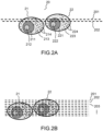
- FIG. 2A, FIG. 2B , FIG. 3A, FIG. 3B , FIG. 3C, FIG.3D This first embodiment describes a first mode of acquisition and calculation of an image of an object field of a section.
- the object focal plane of the microscope objective is moved within said section, in an axial direction parallel to the optical axis of the microscope objective.
- FIG. 2A represents a cluster 20 of two cells 21, 22 of which we seek to make a three-dimensional tomographic image.
- Each cell comprises a nucleus 211, 221 with a nucleolus 212, 222 and around the nucleus a cytoplasm 213, 223 within in which there are cellular organelles 214, 224 such as mitochondria, vesicles, lipid bodies, protein condensates, etc.
- Organelles in the cytoplasm or internal structures of the nucleus of cells scatter light.
- the phase of the interferometric signal it is possible to calculate an image of the section in the volume of the cell, for example by pixel-by-pixel difference between the two acquired interferometric signals.
- the dotted lines 201, 202 illustrate by way of example two positions of the object focal plane of the objective within the section that one seeks to image. To explain the principle of calculating an image of a section according to the first embodiment, it is assumed that the electromagnetic field received in the detection plane 141 of the acquisition device 140 ( FIG.
- 1A is the superposition of the incident field emitted by the source and transmitted by the sample, modeled in this example by a plane wave, and the field scattered by the cell, modeled at the level of each voxel of the object field by a Gaussian beam which lends itself well to an analytical formulation.
- the conclusions developed below remain valid in the cases of an illumination beam which is not strictly a plane wave or of a scattered beam which is not strictly assimilated to a Gaussian beam.
- the beam scattered by the entire object field can in fact be considered as a plurality of beams arranged next to each other throughout the field of the biological object, the size of each beam being defined by the resolution of the microscope objective.
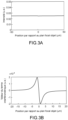
- the intensity of the interference term tends towards 0, because sin(atan(z)) tends towards 0, and the prefactor (1/(1+z 2 )) also tends towards 0 when z becomes large.
- the phase shift of - ⁇ /2 and ⁇ /2 occurs over distances of the order of the depth of field z 0 of the microscope objective.
- objectives with a high numerical aperture For example, with oil immersion objectives with a numerical aperture of 1.25, the depth of field is 0.5 ⁇ m, while with water objectives with a numerical aperture of often 0.9, the depth of field is 1 ⁇ m.
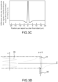
- the piezoelectric elements are not always suitable for making an instantaneous displacement in a slot, and we may prefer to make a sinusoidal modulation of the displacement.
- the variation of the optical signal is also sinusoidal, which we know very well how to filter by synchronous detection by taking 4 images for example.
- the difference between the two-dimensional interferometric signals is then calculated to determine an image of a first section, then the object focal plane is moved and new acquisitions are carried out to determine an image of a following section.
- the object focal plane can be moved in a plane referenced 203 and an interferometric signal acquired in this plane, the difference with the interferometric signal acquired in the plane 202 is taken to calculate an image of another optical section, and so on.
- the relative position of the microscope objective and the sample can also be periodically modulated by applying a sinusoidal voltage to one of the two piezoelectric displacements of the FIG. 1 .
- Synchronous detection of the signals is then carried out by taking a time sample of at least 2 images over a half period.
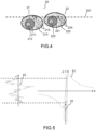
- FIG. 4 and FIG. 5 A second embodiment of a three-dimensional imaging method which is not covered by the claims is described by means of FIG. 4 and FIG. 5 .
- This second embodiment describes another mode of acquisition and calculation of an image of a section, different from that described in relation to the previous figures. Note that it is possible to calculate for each section a first image comprising the first embodiment and a second image corresponding to the second embodiment.
- a relative displacement of the microscope objective and the sample is performed to measure intensity differences at two different positions.
- the microscope objective is not moved relative to the sample for calculating an image of an optical section, as detailed below. Relative movement is only performed to calculate images of different optical sections and thereby reconstruct a three-dimensional image.
- an image of an object field of an optical section is calculated from temporal variations in intensity between said two-dimensional interferometric signals acquired for a given position of the object focal plane within the section.
- a pixel value as a function of a value of a parameter representative of the temporal variations in the intensity of said two-dimensional interferometric signals acquired by said elementary detector.
- the parameter is for example representative of the temporal dispersion of the intensities of the interferometric signals.
- the fluctuations or temporal variation of the intensity signal inform us about the fluctuation of the position of the scatterers.
- the measured intensity signal must be purely random with a ⁇ I which must increase statistically as t (or as the square root of the time difference between images).
- ⁇ I which must increase statistically as t (or as the square root of the time difference between images).
- the physiology of the cell means that the movements are no longer random, but biased, because the cell controls the movement of the scatterers (for example by molecular motors). It has been shown that by measuring the fluctuation of the intensity signal created by the movement of the diffusers, we obtained a specific signal dependent on the metabolism of the cell.
- each pixel of the camera records a signal which is a time series that must be analyzed and represented.
- the Fourier transform of the time series of the interferometric signals to deduce a plurality of values of the pixel, for example values corresponding respectively to the power (integral over the spectrum of the modulus squared of the TF), to the central frequency of the frequency spectrum (H) and to the spectral width (S).
- HSV color representation for "Hue, Saturation, Value” or " Tint, Saturation, Value ”
- V the power
- FIG. 6 represents images of two sections of HeLa cancer cells separated by 4 microns and obtained using an imaging system according to the present description, similar to that shown in the FIG. 1A .
- the microscope objective is a 100X oil immersion objective with a numerical aperture of 1.25 and the central wavelength is equal to 450 nanometers.
- the camera used is a Photon Focus ® MV-D1024E Series CMOS camera.
- the object focal plane of the microscope objective is moved to be centered on two sections of the cell, a first section at the cytoplasm (61, 63) and a second section at the cell nucleus (62, 64).
- These images illustrate the ability of the method which is the subject of the present description to tomograph cells.
- the lower images 63, 64 represent the morphology of the cell, the upper images 61, 62 the "dynamic" part.
- the scale bar is equal to 2 microns.
Landscapes
- Physics & Mathematics (AREA)
- General Physics & Mathematics (AREA)
- Health & Medical Sciences (AREA)
- General Health & Medical Sciences (AREA)
- Nuclear Medicine, Radiotherapy & Molecular Imaging (AREA)
- Radiology & Medical Imaging (AREA)
- Investigating Or Analysing Materials By Optical Means (AREA)
- Microscoopes, Condenser (AREA)
Claims (11)
- Verfahren zur dreidimensionalen Bildgebung durch optische Vollfeldtomographie eines transparenten biologischen Objekts in einer biologischen Probe (10), wobei das Verfahren zur dreidimensionalen Bildgebung umfasst:- Positionieren der Probe in der Nähe einer Objektbrennebene (125) eines Mikroskopobjektivs (121), wobei das Mikroskopobjektiv eine gegebene optische Achse (Δ) umfasst;- Beleuchten der Probe in Transmission mittels eines Beleuchtungsstrahls aus räumlich inkohärentem Licht und einer gegebenen zentralen Wellenlänge (λ);- relatives Verschieben des Mikroskopobjektivs in Bezug auf die Probe gemäß einer axialen Richtung parallel zur optischen Achse des Mikroskopobjektivs, um eine Vielzahl von Positionen der Probe zu definieren, wobei jede Position einem Abschnitt (101) des biologischen Objekts entspricht, der auf die Objektbrennebene des Mikroskopobjektivs zentriert ist; und- für jede Position der Probe, Erzeugen mindestens eines ersten Bildes eines Objektfeldes des Abschnitts, umfassend:- Erfassen, mittels einer Vorrichtung zur zweidimensionalen Erfassung (140), die eine Vielzahl in einer Detektionsebene (141) angeordneter Elementardetektoren umfasst, einer Vielzahl zweidimensionaler interferometrischer Signale, die aus optischen Interferenzen zwischen dem auf das Objektfeld auftreffenden Beleuchtungsstrahl und einem von dem Objektfeld gestreuten Strahl resultieren, wobei die Detektionsebene durch ein optisches Bildgebungssystem, welches das Mikroskopobjektiv umfasst, optisch mit der Objektbrennebene des Mikroskopobjektivs konjugiert ist;- Berechnen, mittels einer Verarbeitungseinheit (150), des mindestens einen ersten Bildes aus der Vielzahl zweidimensionaler interferometrischer Signale.
- Bildgebungsverfahren nach Anspruch 1, wobei die zweidimensionalen interferometrischen Signale der Vielzahl von zweidimensionalen interferometrischen Signalen für unterschiedliche Positionen der Objektbrennebene in der Dicke des Abschnitts erfasst werden, was zu einer Vielzahl von vorbestimmten Phasenverschiebungen zwischen dem Beleuchtungsstrahl und dem gestreuten Strahl führt, die zwischen -π/2 und π/2 liegen.
- Bildgebungsverfahren nach Anspruch 2, wobei:- die Berechnung des mindestens einen ersten Bildes eine lineare Kombination der zweidimensionalen interferometrischen Signale der Vielzahl zweidimensionaler interferometrischer Signale umfasst.
- Bildgebungsverfahren nach einem der Ansprüche 2 oder 3, wobei die relative Verschiebung des Mikroskopobjektivs in Bezug auf die Probe einer periodischen Funktion mit einer maximalen Amplitude von λ/4 folgt, wobei λ die zentrale Wellenlänge des Beleuchtungsstrahls ist.
- Bildgebungsverfahren nach einem der vorstehenden Ansprüche, wobei:- die zweidimensionalen interferometrischen Signale der Vielzahl von zweidimensionalen interferometrischen Signalen für eine feste Position des Mikroskopobjektivs relativ zur Probe erfasst werden, und- die Berechnung des mindestens einen ersten Bildes des Objektfeldes des Abschnitts die Berechnung mindestens eines Pixelwerts für jeden Elementardetektor der Vorrichtung zur zweidimensionalen Erfassung in Abhängigkeit eines Wertes eines Parameters umfasst, der die zeitlichen Intensitätsschwankungen der vom Elementardetektor erfassten zweidimensionalen interferometrischen Signale darstellt.
- Bildgebungsverfahren nach Anspruch 5, wobei der Parameter die zeitliche Streuung der Intensitäten der interferometrischen Signale darstellt.
- System zur dreidimensionalen Bildgebung (100) durch optische Vollfeldtomographie eines transparenten biologischen Objekts in einer biologischen Probe (10), wobei das Bildgebungssystem umfasst:- eine Lichtquelle (110), die konfiguriert ist, um einen Beleuchtungsstrahl aus räumlich inkohärentem Licht mit einer gegebenen zentralen Länge zu emittieren, wobei der Beleuchtungsstrahl konfiguriert ist, um die Probe in Transmission zu beleuchten;- ein optisches Bildgebungssystem (120), das ein Mikroskopobjektiv (121) mit einer gegebenen optischen Achse (Δ) und einer gegebenen Objektbrennebene (125) umfasst, in deren Nähe im Betrieb die Probe (10) positioniert ist;- Mittel zur relativen Verschiebung (131, 132, 135) des Mikroskopobjektivs relativ zur Probe gemäß einer axialen Richtung parallel zur optischen Achse des Mikroskopobjektivs;- eine Vorrichtung zur zweidimensionalen Erfassung (140), die eine Vielzahl von Elementardetektoren umfasst, die in einer Detektionsebene (141) angeordnet sind, wobei die Detektionsebene durch das optische Bildgebungssystem optisch mit der Objektbrennebene des Mikroskopobjektivs konjugiert ist; und- eine Verarbeitungseinheit (150);und wobei für jeden Abschnitt einer Vielzahl von Abschnitten des biologischen Objekts:- das System zur dreidimensionalen Bildgebung für die Erfassung einer Vielzahl zweidimensionaler interferometrischer Signale mittels der Vorrichtung zur zweidimensionalen Erfassung (140) konfiguriert ist, die aus optischen Interferenzen zwischen dem Beleuchtungsstrahl und einem von einem Objektfeld des Abschnitts gestreuten Strahl resultieren;- die Verarbeitungseinheit (150) konfiguriert ist, um aus der Vielzahl zweidimensionaler interferometrischer Signale mindestens ein erstes Bild des Objektfeldes des Abschnitts zu berechnen.
- Bildgebungssystem nach Anspruch 7, wobei die zweidimensionalen interferometrischen Signale der Vielzahl von zweidimensionalen interferometrischen Signalen für unterschiedliche Positionen der Objektbrennebene in der Dicke des Abschnitts erfasst werden, was zu einer Vielzahl von vorbestimmten Phasenverschiebungen zwischen dem Beleuchtungsstrahl und dem gestreuten Strahl führt, die zwischen -π/2 und π/2 liegen.
- Bildgebungssystem nach Anspruch 8, wobei die Berechnung des mindestens einen ersten Bildes eine lineare Kombination der zweidimensionalen interferometrischen Signale der Vielzahl von zweidimensionalen interferometrischen Signalen umfasst.
- Bildgebungssystem nach einem der Ansprüche 7 bis 9, wobei die zweidimensionalen interferometrischen Signale der Vielzahl von zweidimensionalen interferometrischen Signalen für eine feste Position des Mikroskopobjektivs relativ zur Probe erfasst werden, und die Berechnung des mindestens einen ersten Bildes des Objektfeldes des Abschnitts umfasst:- die Berechnung mindestens eines Pixelwerts für jeden Elementardetektor der Vorrichtung zur zweidimensionalen Erfassung in Abhängigkeit eines Wertes eines Parameters, der die zeitlichen Intensitätsschwankungen der vom Elementardetektor erfassten zweidimensionalen interferometrischen Signale darstellt.
- Bildgebungssystem nach Anspruch 10, wobei der Parameter die zeitliche Streuung der Intensitäten der zweidimensionalen interferometrischen Signale darstellt.
Applications Claiming Priority (2)
| Application Number | Priority Date | Filing Date | Title |
|---|---|---|---|
| FR2105600A FR3123427B1 (fr) | 2021-05-28 | 2021-05-28 | Procédés et systèmes d’imagerie tridimensionnelle d’un objet biologique transparent dans un échantillon biologique par tomographie optique plein champ |
| PCT/EP2022/063907 WO2022248407A1 (fr) | 2021-05-28 | 2022-05-23 | Procedes et systemes d'imagerie tridimensionnelle d'un objet biologique transparent dans un echantillon biologique par tomographie optique plein champ |
Publications (3)
| Publication Number | Publication Date |
|---|---|
| EP4348167A1 EP4348167A1 (de) | 2024-04-10 |
| EP4348167C0 EP4348167C0 (de) | 2025-07-02 |
| EP4348167B1 true EP4348167B1 (de) | 2025-07-02 |
Family
ID=77317078
Family Applications (1)
| Application Number | Title | Priority Date | Filing Date |
|---|---|---|---|
| EP22730221.3A Active EP4348167B1 (de) | 2021-05-28 | 2022-05-23 | Verfahren und systeme zur dreidimensionalen bildgebung eines transparenten biologischen objekts in einer biologischen probe mittels optischer vollfeldtomografie |
Country Status (5)
| Country | Link |
|---|---|
| US (1) | US20250044075A1 (de) |
| EP (1) | EP4348167B1 (de) |
| JP (1) | JP2024519558A (de) |
| FR (1) | FR3123427B1 (de) |
| WO (1) | WO2022248407A1 (de) |
Family Cites Families (6)
| Publication number | Priority date | Publication date | Assignee | Title |
|---|---|---|---|---|
| FR2817030B1 (fr) | 2000-11-17 | 2003-03-28 | Centre Nat Rech Scient | Procede et dispositif d'imagerie microscopique interferentielle d'un objet a haute cadence |
| JP2009264787A (ja) * | 2008-04-22 | 2009-11-12 | Topcon Corp | 光画像計測装置 |
| EP2562245B1 (de) * | 2010-04-23 | 2016-09-28 | Hamamatsu Photonics K.K. | Zellbeobachtungsvorrichtung und zellbeobachtungsverfahren |
| FR3034858B1 (fr) | 2015-04-10 | 2017-05-26 | Lltech Man | Procede et systeme d'imagerie par microscopie interferentielle plein champ |
| JP6886306B2 (ja) * | 2017-02-02 | 2021-06-16 | オリンパス株式会社 | 位相分布算出方法、評価方法、画像処理装置、画像処理システム、プログラム |
| JP7253457B2 (ja) * | 2019-06-25 | 2023-04-06 | 株式会社Screenホールディングス | 補正方法、補正装置および撮像装置 |
-
2021
- 2021-05-28 FR FR2105600A patent/FR3123427B1/fr active Active
-
2022
- 2022-05-23 US US18/564,270 patent/US20250044075A1/en active Pending
- 2022-05-23 JP JP2023573596A patent/JP2024519558A/ja active Pending
- 2022-05-23 WO PCT/EP2022/063907 patent/WO2022248407A1/fr not_active Ceased
- 2022-05-23 EP EP22730221.3A patent/EP4348167B1/de active Active
Also Published As
| Publication number | Publication date |
|---|---|
| WO2022248407A1 (fr) | 2022-12-01 |
| FR3123427A1 (fr) | 2022-12-02 |
| US20250044075A1 (en) | 2025-02-06 |
| EP4348167C0 (de) | 2025-07-02 |
| JP2024519558A (ja) | 2024-05-16 |
| FR3123427B1 (fr) | 2023-05-26 |
| EP4348167A1 (de) | 2024-04-10 |
Similar Documents
| Publication | Publication Date | Title |
|---|---|---|
| Qian et al. | Video-rate high-precision time-frequency multiplexed 3D coherent ranging | |
| Cua et al. | Imaging moving targets through scattering media | |
| EP3433679B1 (de) | Verfahren zur beobachtung einer probe durch berechnung eines komplexen bildes | |
| EP3274694B1 (de) | Verfahren zur bestimmung des zustandes einer zelle | |
| Kempe et al. | Comparative study of confocal and heterodyne microscopy for imaging through scattering media | |
| EP3204755B1 (de) | Verfahren und vorrichtung zur optischen detektion von nanopartikeln in einer flüssigkeitsprobe | |
| EP3519899B1 (de) | Vorrichtung zur beobachtung einer probe und verfahren zur beobachtung einer probe | |
| FR3015659A1 (fr) | Appareil et procede de tomographie optique | |
| FR3049348A1 (fr) | Procede de caracterisation d’une particule dans un echantillon | |
| EP2220480A2 (de) | Hochauflösendes oberflächenplasmonenmikroskop mit heterodyner interferometrie im radialen polarisationsmodus | |
| WO2011125033A1 (fr) | Procédé de détection d'amas de particules biologiques. | |
| EP3199941A1 (de) | Beobachtungsverfahren einer probe mittels bildgebungssystem ohne linse | |
| EP3201563A1 (de) | Diffraktionsmikroskopverfahren und -vorrichtung | |
| EP4260116B1 (de) | Konfokales mikroskop mit photonen-umverteilung | |
| EP4307051B1 (de) | Verfahren und system zur charakterisierung von mikroorganismen mittels digitaler holographischer mikroskopie | |
| EP3371574B1 (de) | Vorrichtung und verfahren zur beobachtung eines objekts mittels linsenfreier abbildung | |
| EP4348167B1 (de) | Verfahren und systeme zur dreidimensionalen bildgebung eines transparenten biologischen objekts in einer biologischen probe mittels optischer vollfeldtomografie | |
| FR3100333A1 (fr) | Dispositif et procédé de détermination de paramètres caractéristiques des dimensions de nanoparticules | |
| Santos et al. | Confocal LiDAR for remote high-resolution imaging of auto-fluorescence in aquatic media | |
| EP4022280A1 (de) | Verfahren und vorrichtung zur optischen charakterisierung von partikeln | |
| FR3100335A1 (fr) | Méthode et dispositif de caractérisation optique de particules | |
| Kassem et al. | Time-of-flight widefield microscopy | |
| WO2023073220A1 (fr) | Systèmes de caractérisation d'une région d'intérêt d'un tissu biologique | |
| EP2486391A1 (de) | Verfahren und system zur strukturanalyse eines objekts durch messung dessen wellenfront | |
| Indebetouw | Scanning holographic microscopy with spatially incoherent sources: reconciling the holographic advantage with the sectioning advantage |
Legal Events
| Date | Code | Title | Description |
|---|---|---|---|
| STAA | Information on the status of an ep patent application or granted ep patent |
Free format text: STATUS: UNKNOWN |
|
| STAA | Information on the status of an ep patent application or granted ep patent |
Free format text: STATUS: THE INTERNATIONAL PUBLICATION HAS BEEN MADE |
|
| PUAI | Public reference made under article 153(3) epc to a published international application that has entered the european phase |
Free format text: ORIGINAL CODE: 0009012 |
|
| STAA | Information on the status of an ep patent application or granted ep patent |
Free format text: STATUS: REQUEST FOR EXAMINATION WAS MADE |
|
| 17P | Request for examination filed |
Effective date: 20231129 |
|
| AK | Designated contracting states |
Kind code of ref document: A1 Designated state(s): AL AT BE BG CH CY CZ DE DK EE ES FI FR GB GR HR HU IE IS IT LI LT LU LV MC MK MT NL NO PL PT RO RS SE SI SK SM TR |
|
| DAV | Request for validation of the european patent (deleted) | ||
| DAX | Request for extension of the european patent (deleted) | ||
| GRAP | Despatch of communication of intention to grant a patent |
Free format text: ORIGINAL CODE: EPIDOSNIGR1 |
|
| STAA | Information on the status of an ep patent application or granted ep patent |
Free format text: STATUS: GRANT OF PATENT IS INTENDED |
|
| INTG | Intention to grant announced |
Effective date: 20250115 |
|
| RAP1 | Party data changed (applicant data changed or rights of an application transferred) |
Owner name: ECOLE NORMALE SUPERIEURE DE PARIS Owner name: INSTITUT NATIONAL DE LA SANTE ET DE LA RECHERCHEMEDICALE Owner name: ECOLE SUPERIEURE DE PHYSIQUE ET DE CHIMIEINDUSTRIELLES DE LA VILLE DE PARIS Owner name: CENTRE NATIONAL DE LA RECHERCHE SCIENTIFIQUE |
|
| GRAS | Grant fee paid |
Free format text: ORIGINAL CODE: EPIDOSNIGR3 |
|
| GRAA | (expected) grant |
Free format text: ORIGINAL CODE: 0009210 |
|
| STAA | Information on the status of an ep patent application or granted ep patent |
Free format text: STATUS: THE PATENT HAS BEEN GRANTED |
|
| AK | Designated contracting states |
Kind code of ref document: B1 Designated state(s): AL AT BE BG CH CY CZ DE DK EE ES FI FR GB GR HR HU IE IS IT LI LT LU LV MC MK MT NL NO PL PT RO RS SE SI SK SM TR |
|
| REG | Reference to a national code |
Ref country code: GB Ref legal event code: FG4D Free format text: NOT ENGLISH |
|
| REG | Reference to a national code |
Ref country code: CH Ref legal event code: EP |
|
| REG | Reference to a national code |
Ref country code: DE Ref legal event code: R096 Ref document number: 602022016936 Country of ref document: DE |
|
| REG | Reference to a national code |
Ref country code: IE Ref legal event code: FG4D Free format text: LANGUAGE OF EP DOCUMENT: FRENCH |
|
| U01 | Request for unitary effect filed |
Effective date: 20250717 |
|
| U07 | Unitary effect registered |
Designated state(s): AT BE BG DE DK EE FI FR IT LT LU LV MT NL PT RO SE SI Effective date: 20250728 |
|
| PG25 | Lapsed in a contracting state [announced via postgrant information from national office to epo] |
Ref country code: IS Free format text: LAPSE BECAUSE OF FAILURE TO SUBMIT A TRANSLATION OF THE DESCRIPTION OR TO PAY THE FEE WITHIN THE PRESCRIBED TIME-LIMIT Effective date: 20251102 |
|
| PG25 | Lapsed in a contracting state [announced via postgrant information from national office to epo] |
Ref country code: NO Free format text: LAPSE BECAUSE OF FAILURE TO SUBMIT A TRANSLATION OF THE DESCRIPTION OR TO PAY THE FEE WITHIN THE PRESCRIBED TIME-LIMIT Effective date: 20251002 |
|
| PG25 | Lapsed in a contracting state [announced via postgrant information from national office to epo] |
Ref country code: HR Free format text: LAPSE BECAUSE OF FAILURE TO SUBMIT A TRANSLATION OF THE DESCRIPTION OR TO PAY THE FEE WITHIN THE PRESCRIBED TIME-LIMIT Effective date: 20250702 |
|
| PG25 | Lapsed in a contracting state [announced via postgrant information from national office to epo] |
Ref country code: GR Free format text: LAPSE BECAUSE OF FAILURE TO SUBMIT A TRANSLATION OF THE DESCRIPTION OR TO PAY THE FEE WITHIN THE PRESCRIBED TIME-LIMIT Effective date: 20251003 |
|
| PG25 | Lapsed in a contracting state [announced via postgrant information from national office to epo] |
Ref country code: CZ Free format text: LAPSE BECAUSE OF FAILURE TO SUBMIT A TRANSLATION OF THE DESCRIPTION OR TO PAY THE FEE WITHIN THE PRESCRIBED TIME-LIMIT Effective date: 20250702 |
|
| PG25 | Lapsed in a contracting state [announced via postgrant information from national office to epo] |
Ref country code: PL Free format text: LAPSE BECAUSE OF FAILURE TO SUBMIT A TRANSLATION OF THE DESCRIPTION OR TO PAY THE FEE WITHIN THE PRESCRIBED TIME-LIMIT Effective date: 20250702 |
|
| PG25 | Lapsed in a contracting state [announced via postgrant information from national office to epo] |
Ref country code: RS Free format text: LAPSE BECAUSE OF FAILURE TO SUBMIT A TRANSLATION OF THE DESCRIPTION OR TO PAY THE FEE WITHIN THE PRESCRIBED TIME-LIMIT Effective date: 20251002 |
|
| PG25 | Lapsed in a contracting state [announced via postgrant information from national office to epo] |
Ref country code: ES Free format text: LAPSE BECAUSE OF FAILURE TO SUBMIT A TRANSLATION OF THE DESCRIPTION OR TO PAY THE FEE WITHIN THE PRESCRIBED TIME-LIMIT Effective date: 20250702 |