EP3433679B1 - Verfahren zur beobachtung einer probe durch berechnung eines komplexen bildes - Google Patents
Verfahren zur beobachtung einer probe durch berechnung eines komplexen bildes Download PDFInfo
- Publication number
- EP3433679B1 EP3433679B1 EP17716963.8A EP17716963A EP3433679B1 EP 3433679 B1 EP3433679 B1 EP 3433679B1 EP 17716963 A EP17716963 A EP 17716963A EP 3433679 B1 EP3433679 B1 EP 3433679B1
- Authority
- EP
- European Patent Office
- Prior art keywords
- image
- sample
- pixel
- complex
- plane
- Prior art date
- Legal status (The legal status is an assumption and is not a legal conclusion. Google has not performed a legal analysis and makes no representation as to the accuracy of the status listed.)
- Active
Links
- 238000000034 method Methods 0.000 title claims description 28
- 238000004364 calculation method Methods 0.000 title claims description 13
- 238000001514 detection method Methods 0.000 claims description 47
- 239000013598 vector Substances 0.000 claims description 30
- 238000005286 illumination Methods 0.000 claims description 5
- 230000000694 effects Effects 0.000 claims description 3
- 239000000523 sample Substances 0.000 description 104
- 239000012071 phase Substances 0.000 description 54
- 239000002245 particle Substances 0.000 description 17
- 230000006870 function Effects 0.000 description 14
- 230000003287 optical effect Effects 0.000 description 10
- 210000004027 cell Anatomy 0.000 description 9
- 230000003595 spectral effect Effects 0.000 description 9
- 239000002609 medium Substances 0.000 description 8
- 241000897276 Termes Species 0.000 description 7
- 238000003384 imaging method Methods 0.000 description 7
- 239000007788 liquid Substances 0.000 description 4
- 238000010521 absorption reaction Methods 0.000 description 3
- 238000012550 audit Methods 0.000 description 3
- 239000012472 biological sample Substances 0.000 description 3
- 230000005540 biological transmission Effects 0.000 description 3
- 238000009826 distribution Methods 0.000 description 3
- 210000003743 erythrocyte Anatomy 0.000 description 3
- 239000011159 matrix material Substances 0.000 description 3
- 238000005457 optimization Methods 0.000 description 3
- 230000008569 process Effects 0.000 description 3
- 241000699800 Cricetinae Species 0.000 description 2
- FAPWRFPIFSIZLT-UHFFFAOYSA-M Sodium chloride Chemical compound [Na+].[Cl-] FAPWRFPIFSIZLT-UHFFFAOYSA-M 0.000 description 2
- 239000000872 buffer Substances 0.000 description 2
- 238000012512 characterization method Methods 0.000 description 2
- 230000003247 decreasing effect Effects 0.000 description 2
- 238000011161 development Methods 0.000 description 2
- 230000018109 developmental process Effects 0.000 description 2
- 239000001963 growth medium Substances 0.000 description 2
- 238000004519 manufacturing process Methods 0.000 description 2
- 239000002105 nanoparticle Substances 0.000 description 2
- 238000010606 normalization Methods 0.000 description 2
- 210000001672 ovary Anatomy 0.000 description 2
- 230000001902 propagating effect Effects 0.000 description 2
- 239000011780 sodium chloride Substances 0.000 description 2
- 229920001817 Agar Polymers 0.000 description 1
- 241000894006 Bacteria Species 0.000 description 1
- 240000004808 Saccharomyces cerevisiae Species 0.000 description 1
- 241000607056 Stenodus leucichthys Species 0.000 description 1
- 241001080024 Telles Species 0.000 description 1
- 239000008272 agar Substances 0.000 description 1
- 238000004458 analytical method Methods 0.000 description 1
- 239000007864 aqueous solution Substances 0.000 description 1
- 230000001580 bacterial effect Effects 0.000 description 1
- 210000004369 blood Anatomy 0.000 description 1
- 239000008280 blood Substances 0.000 description 1
- 210000004978 chinese hamster ovary cell Anatomy 0.000 description 1
- 230000001186 cumulative effect Effects 0.000 description 1
- 230000007423 decrease Effects 0.000 description 1
- 238000009792 diffusion process Methods 0.000 description 1
- 239000006185 dispersion Substances 0.000 description 1
- 238000005516 engineering process Methods 0.000 description 1
- 230000002349 favourable effect Effects 0.000 description 1
- 239000000499 gel Substances 0.000 description 1
- 238000001093 holography Methods 0.000 description 1
- 230000006872 improvement Effects 0.000 description 1
- 150000002632 lipids Chemical class 0.000 description 1
- 239000007791 liquid phase Substances 0.000 description 1
- 238000005259 measurement Methods 0.000 description 1
- 239000011325 microbead Substances 0.000 description 1
- 244000005700 microbiome Species 0.000 description 1
- 239000011859 microparticle Substances 0.000 description 1
- 239000013307 optical fiber Substances 0.000 description 1
- 239000008363 phosphate buffer Substances 0.000 description 1
- 230000000750 progressive effect Effects 0.000 description 1
- 230000000644 propagated effect Effects 0.000 description 1
- 230000009467 reduction Effects 0.000 description 1
- 239000007787 solid Substances 0.000 description 1
- 239000000758 substrate Substances 0.000 description 1
- 230000001629 suppression Effects 0.000 description 1
- 239000000725 suspension Substances 0.000 description 1
Images


Classifications
-
- G—PHYSICS
- G01—MEASURING; TESTING
- G01N—INVESTIGATING OR ANALYSING MATERIALS BY DETERMINING THEIR CHEMICAL OR PHYSICAL PROPERTIES
- G01N15/00—Investigating characteristics of particles; Investigating permeability, pore-volume or surface-area of porous materials
- G01N15/10—Investigating individual particles
- G01N15/14—Optical investigation techniques, e.g. flow cytometry
- G01N15/1434—Optical arrangements
-
- G—PHYSICS
- G01—MEASURING; TESTING
- G01N—INVESTIGATING OR ANALYSING MATERIALS BY DETERMINING THEIR CHEMICAL OR PHYSICAL PROPERTIES
- G01N15/00—Investigating characteristics of particles; Investigating permeability, pore-volume or surface-area of porous materials
- G01N15/10—Investigating individual particles
- G01N15/14—Optical investigation techniques, e.g. flow cytometry
- G01N15/1429—Signal processing
- G01N15/1433—Signal processing using image recognition
-
- G—PHYSICS
- G03—PHOTOGRAPHY; CINEMATOGRAPHY; ANALOGOUS TECHNIQUES USING WAVES OTHER THAN OPTICAL WAVES; ELECTROGRAPHY; HOLOGRAPHY
- G03H—HOLOGRAPHIC PROCESSES OR APPARATUS
- G03H1/00—Holographic processes or apparatus using light, infrared or ultraviolet waves for obtaining holograms or for obtaining an image from them; Details peculiar thereto
- G03H1/04—Processes or apparatus for producing holograms
- G03H1/0443—Digital holography, i.e. recording holograms with digital recording means
-
- G—PHYSICS
- G03—PHOTOGRAPHY; CINEMATOGRAPHY; ANALOGOUS TECHNIQUES USING WAVES OTHER THAN OPTICAL WAVES; ELECTROGRAPHY; HOLOGRAPHY
- G03H—HOLOGRAPHIC PROCESSES OR APPARATUS
- G03H1/00—Holographic processes or apparatus using light, infrared or ultraviolet waves for obtaining holograms or for obtaining an image from them; Details peculiar thereto
- G03H1/04—Processes or apparatus for producing holograms
- G03H1/08—Synthesising holograms, i.e. holograms synthesized from objects or objects from holograms
- G03H1/0866—Digital holographic imaging, i.e. synthesizing holobjects from holograms
-
- G—PHYSICS
- G01—MEASURING; TESTING
- G01N—INVESTIGATING OR ANALYSING MATERIALS BY DETERMINING THEIR CHEMICAL OR PHYSICAL PROPERTIES
- G01N15/00—Investigating characteristics of particles; Investigating permeability, pore-volume or surface-area of porous materials
- G01N15/10—Investigating individual particles
- G01N2015/1006—Investigating individual particles for cytology
-
- G—PHYSICS
- G01—MEASURING; TESTING
- G01N—INVESTIGATING OR ANALYSING MATERIALS BY DETERMINING THEIR CHEMICAL OR PHYSICAL PROPERTIES
- G01N15/00—Investigating characteristics of particles; Investigating permeability, pore-volume or surface-area of porous materials
- G01N15/10—Investigating individual particles
- G01N15/14—Optical investigation techniques, e.g. flow cytometry
- G01N15/1434—Optical arrangements
- G01N2015/144—Imaging characterised by its optical setup
-
- G—PHYSICS
- G01—MEASURING; TESTING
- G01N—INVESTIGATING OR ANALYSING MATERIALS BY DETERMINING THEIR CHEMICAL OR PHYSICAL PROPERTIES
- G01N15/00—Investigating characteristics of particles; Investigating permeability, pore-volume or surface-area of porous materials
- G01N15/10—Investigating individual particles
- G01N15/14—Optical investigation techniques, e.g. flow cytometry
- G01N15/1434—Optical arrangements
- G01N2015/1454—Optical arrangements using phase shift or interference, e.g. for improving contrast
-
- G—PHYSICS
- G03—PHOTOGRAPHY; CINEMATOGRAPHY; ANALOGOUS TECHNIQUES USING WAVES OTHER THAN OPTICAL WAVES; ELECTROGRAPHY; HOLOGRAPHY
- G03H—HOLOGRAPHIC PROCESSES OR APPARATUS
- G03H1/00—Holographic processes or apparatus using light, infrared or ultraviolet waves for obtaining holograms or for obtaining an image from them; Details peculiar thereto
- G03H1/04—Processes or apparatus for producing holograms
- G03H1/0443—Digital holography, i.e. recording holograms with digital recording means
- G03H2001/0447—In-line recording arrangement
-
- G—PHYSICS
- G03—PHOTOGRAPHY; CINEMATOGRAPHY; ANALOGOUS TECHNIQUES USING WAVES OTHER THAN OPTICAL WAVES; ELECTROGRAPHY; HOLOGRAPHY
- G03H—HOLOGRAPHIC PROCESSES OR APPARATUS
- G03H1/00—Holographic processes or apparatus using light, infrared or ultraviolet waves for obtaining holograms or for obtaining an image from them; Details peculiar thereto
- G03H1/04—Processes or apparatus for producing holograms
- G03H1/0443—Digital holography, i.e. recording holograms with digital recording means
- G03H2001/045—Fourier or lensless Fourier arrangement
-
- G—PHYSICS
- G03—PHOTOGRAPHY; CINEMATOGRAPHY; ANALOGOUS TECHNIQUES USING WAVES OTHER THAN OPTICAL WAVES; ELECTROGRAPHY; HOLOGRAPHY
- G03H—HOLOGRAPHIC PROCESSES OR APPARATUS
- G03H1/00—Holographic processes or apparatus using light, infrared or ultraviolet waves for obtaining holograms or for obtaining an image from them; Details peculiar thereto
- G03H1/04—Processes or apparatus for producing holograms
- G03H1/0443—Digital holography, i.e. recording holograms with digital recording means
- G03H2001/0452—Digital holography, i.e. recording holograms with digital recording means arranged to record an image of the object
-
- G—PHYSICS
- G03—PHOTOGRAPHY; CINEMATOGRAPHY; ANALOGOUS TECHNIQUES USING WAVES OTHER THAN OPTICAL WAVES; ELECTROGRAPHY; HOLOGRAPHY
- G03H—HOLOGRAPHIC PROCESSES OR APPARATUS
- G03H1/00—Holographic processes or apparatus using light, infrared or ultraviolet waves for obtaining holograms or for obtaining an image from them; Details peculiar thereto
- G03H1/04—Processes or apparatus for producing holograms
- G03H1/0443—Digital holography, i.e. recording holograms with digital recording means
- G03H2001/0454—Arrangement for recovering hologram complex amplitude
-
- G—PHYSICS
- G03—PHOTOGRAPHY; CINEMATOGRAPHY; ANALOGOUS TECHNIQUES USING WAVES OTHER THAN OPTICAL WAVES; ELECTROGRAPHY; HOLOGRAPHY
- G03H—HOLOGRAPHIC PROCESSES OR APPARATUS
- G03H1/00—Holographic processes or apparatus using light, infrared or ultraviolet waves for obtaining holograms or for obtaining an image from them; Details peculiar thereto
- G03H1/04—Processes or apparatus for producing holograms
- G03H1/08—Synthesising holograms, i.e. holograms synthesized from objects or objects from holograms
- G03H1/0808—Methods of numerical synthesis, e.g. coherent ray tracing [CRT], diffraction specific
- G03H2001/0816—Iterative algorithms
Definitions
- the technical field of the invention is related to the observation of a sample, in particular a biological sample, by lensless imaging.
- This image is formed of interference figures between the light wave emitted by the light source and transmitted by the sample, and diffraction waves, resulting from the diffraction by the sample of the light wave emitted by the source from light.
- These interference figures are sometimes called diffraction figures, or designated by the English term “diffraction pattern”.
- the document WO2008090330 describes a device allowing the observation of biological samples, in this case cells, by lensless imaging.
- the device makes it possible to associate, with each cell, an interference figure whose morphology makes it possible to identify the type of cell.
- Lensless imaging therefore appears to be a simple and inexpensive alternative to a conventional microscope.
- its field of observation is much larger than that of a microscope. It is therefore understood that the application prospects linked to this technology are important.
- the image formed on the image sensor can be processed by a holographic reconstruction algorithm, so as to estimate optical properties of the sample, for example a factor transmission or a phase.
- a holographic reconstruction algorithm so as to estimate optical properties of the sample, for example a factor transmission or a phase.
- Such algorithms are well known in the field of holographic reconstruction. For this, the distance between the sample and the image sensor being known, we apply a propagation algorithm, taking into account this distance, as well as the length wave of the light wave emitted by the light source. It is then possible to reconstitute an image of an optical property of the sample.
- the reconstructed image can, in particular, be a complex image of the light wave transmitted by the sample, comprising information on the optical properties of absorption or of phase variation of the sample.
- the holographic reconstruction algorithms can induce reconstruction noise in the reconstructed image, referred to by the term “twin image”. This is essentially due to the fact that the image formed on the image sensor does not include information relating to the phase of the light wave reaching this sensor. Therefore, the holographic reconstruction is carried out on the basis of partial optical information, based solely on the intensity of the light wave collected on the image sensor.
- the improvement of the quality of the holographic reconstruction is the subject of numerous developments, by implementing algorithms frequently referred to as “Phase retrieval”, allowing an estimate of the phase of the light wave to which the image sensor is exposed. .
- a digital reconstruction algorithm is for example described in US2012 / 0218379 .
- the inventors propose a method of observing a sample by a holographic imaging method, the method comprising a step of reconstructing a complex image of the sample. This reconstruction step makes it possible to obtain a complex image of good quality, giving information on the optical properties of the sample.
- the norm calculated at each pixel is preferably a norm of order less than or equal to 1.
- the noise indicator quantifies the reconstruction noise affecting the reconstructed complex image. It may be a standard of order less than or equal to 1 calculated from the quantities associated with each pixel.
- the magnitude associated with each pixel can be calculated from the modulus of a dimensional derivative, at said pixel, of the complex image determined during sub-step ii).
- the reconstruction plane may preferably extend parallel to, or substantially parallel to the detection plane.
- the reconstruction plane is a plane along which the sample extends.
- no magnification optics are interposed between the sample and the image sensor.
- the method may include a step d) of characterizing the sample as a function of the complex image calculated.
- the figure 1 represents an example of a device according to the invention.
- a light source 11 is able to emit a light wave 12, called an incident light wave, propagating in the direction of a sample 10, along a propagation axis Z.
- the light wave is emitted according to a spectral band ⁇ , comprising a wavelength ⁇ . This wavelength can be a central wavelength of said spectral band.
- Sample 10 is a sample that one wishes to characterize. It may in particular be a medium 10a comprising particles 10b.
- the particles 10b can be blood particles, for example red blood cells. They may also be cells, microorganisms, for example bacteria or yeasts, microalgae, microbeads, or droplets which are insoluble in the liquid medium, for example lipid nanoparticles.
- the particles 10b have a diameter, or are inscribed in a diameter, of less than 1 mm, and preferably of less than 100 ⁇ m. These are microparticles (diameter less than 1 mm) or nanoparticles (diameter less than 1 ⁇ m).
- the medium 10a in which the particles bathe, can be a liquid medium, for example a liquid phase of a bodily liquid, of a culture medium or of a liquid taken from the environment or in an industrial process. It can also be a solid medium or one having the consistency of a gel, for example a substrate of agar type, suitable for the growth of bacterial colonies.
- the sample 10 is contained in a fluidic chamber 15.
- the fluidic chamber 15 is for example a microcuvette, in common use in point-of-care type devices, into which the sample 20 penetrates, for example by capillarity.
- the thickness e of the sample 10, along the axis of propagation typically varies between 20 ⁇ m and 1 cm, and is preferably between 50 ⁇ m and 500 ⁇ m, for example 150 ⁇ m.
- the sample extends along a plane P 10 , called the plane of the sample, perpendicular to the axis of propagation. It is maintained on a 10s support.
- the distance D between the light source 11 and the sample 10 is preferably greater than 1 cm. It is preferably between 2 and 30 cm.
- the light source seen by the sample is considered to be point. This means that its diameter (or its diagonal) is preferably less than a tenth, better still a hundredth of the distance between the sample and the light source.
- the light reaches the sample in the form of plane waves, or which can be considered as such.
- the light source 11 can be a light emitting diode or a laser diode. It can be associated with diaphragm 18, or spatial filter.
- the opening of the diaphragm is typically between 5 ⁇ m and 1 mm, preferably between 50 ⁇ m and 500 ⁇ m.
- the diaphragm is supplied by Thorlabs under the reference P150S and its diameter is 150 ⁇ m.
- the diaphragm can be replaced by an optical fiber, a first end of which is placed facing the light source 11 and a second end of which is placed facing the sample 10.
- the device preferably comprises a diffuser 17, arranged between the light source 11 and the diaphragm 18.
- a diffuser 17 makes it possible to overcome the constraints of centering the light source 11 with respect to the opening. of the diaphragm 18.
- the function of such a diffuser is to distribute the light beam, produced by an elementary light source 11 i , (1 ⁇ i ⁇ 3) according to a cone of angle a, a being equal to 30 ° in the present case.
- the angle of diffusion ⁇ varies between 10 ° and 80 °.
- the spectral emission band ⁇ of the incident light wave 12 has a width of less than 100 nm.
- spectral bandwidth is meant a width at mid-height of said spectral band.
- the sample 10 is disposed between the light source 11 and an image sensor 16.
- the latter preferably extends parallel, or substantially parallel to the plane along which the sample extends.
- substantially parallel means that the two elements may not be strictly parallel, an angular tolerance of a few degrees, less than 20 ° or 10 ° being allowed.
- the image sensor 16 is able to form an image according to a detection plane P 0 .
- a detection plane P 0 is an image sensor comprising a matrix of pixels, of the CCD type or a CMOS.
- CMOS are the preferred sensors because the pixel size is smaller, which makes it possible to acquire images with more favorable spatial resolution.
- the detection plane P 0 preferably extends perpendicularly to the axis of propagation Z of the incident light wave 12.
- the distance d between the sample 10 and the matrix of pixels of the image sensor 16 is preferably between 50 ⁇ m and 2 cm, preferably between 100 ⁇ m and 2 mm.
- the light wave 22 may also be referred to by the term exposure light wave.
- a processor 20, for example a microprocessor, is able to process each image acquired by the image sensor 16.
- the processor is a microprocessor linked to a programmable memory 22 in which is stored a sequence of instructions for performing the operations. image processing and calculation operations described in this description.
- the processor can be coupled to a screen 24 allowing the display of images acquired by the image sensor 16 or calculated by the processor 20.
- An image acquired on the image sensor 16, also called a hologram, does not make it possible to obtain a sufficiently precise representation of the observed sample.
- a propagation operator h it is possible to apply, to each image acquired by the image sensor, a propagation operator h , so as to calculate a quantity representative of the light wave 22 transmitted by the sample 10 , and to which the image sensor 16 is exposed.
- Such a method designated by the term holographic reconstruction, makes it possible in particular to reconstruct an image of the module or of the phase of this light wave 22 in a reconstruction plane parallel to the plane of. detection P 0 , and in particular in the plane P 10 along which the sample extends. For this, we perform a convolution product of the image I 0 acquired by extends the sample.
- a convolution product of the image I 0 acquired by the image sensor 16 is carried out by a propagation operator h . It is then possible to reconstruct a complex expression A of the light wave 22 at any coordinate point ( x, y, z ) in space, and in particular in a reconstruction plane P z located at a distance
- the complex expression A is a complex quantity whose argument and modulus are respectively representative of the phase and of the intensity of the light wave 22 to which the image sensor 16 is exposed.
- the convolution product of l 'image I 0 by the propagation operator h makes it possible to obtain a complex image A z representing a spatial distribution of the complex expression A in a plane, called the reconstruction plane P z , extending to a coordinate z of the plane detection P 0 .
- This complex image corresponds to a complex image of the sample in the reconstruction plane P z . It also represents a two-dimensional spatial distribution of the optical properties of wave 22 to which image sensor 16 is exposed.
- the function of the propagation operator h is to describe the propagation of light between the image sensor 16 and a point of coordinates ( x, y, z ), located at a distance
- a z representing a spatial distribution of the complex amplitude A ( x, y, z ) at a distance
- Such an image is representative of the light wave 22 to which the image sensor 16 is exposed and in particular allows access to the module or to the phase of this light wave.
- Step 100 image acquisition :
- the image sensor 16 acquires an image I 0 of the sample 16, and more precisely of the light wave 22 transmitted by the latter, to which the image sensor is exposed.
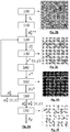
- image I 0 Such an image, or hologram, is shown on the figure 2B .
- This image was produced using a sample comprising CHO cells (hamster ovary cells) bathed in a saline buffer, the sample being contained in a fluidic chamber 100 ⁇ m thick placed at a distance d of 1500 ⁇ m d ' a CMOS sensor.
- Step 110 initialization :
- Step 120 propagation :
- the image AT 0 k - 1 obtained in the detection plane is propagated in a reconstruction plane P z , by the application of a propagation operator as previously described, so as to obtain a complex image AT z k , representative of the sample, in the reconstruction plane P z .
- the term complex image designates the fact that each term of this image is a complex quantity.
- the index - z represents the fact that the propagation is carried out in a direction opposite to the axis of propagation Z. We speak of back-propagation.
- r and r ' respectively denote radial coordinates, that is to say in the reconstruction plane P z and in the detection plane P 0 .
- AT 0 k - 1 is the complex image in the detection plane P 0 updated during the previous iteration.
- the reconstruction plane P z is a plane distant from the detection plane P 0 , and preferably parallel to the latter.
- the reconstruction plane P z is a plane P 10 along which the sample 10 extends.
- an image reconstructed in this plane makes it possible to obtain a generally high spatial resolution.
- It can also be another plane, located a generally high spatial resolution.
- It can also be another plane, located at a non-zero distance from the detection plane, and preferably parallel to the latter, for example a plane extending between the image sensor 16 and the sample 10.
- This image represents the complex image, in the reconstruction plane, established during the first iteration.
- Step 130 Calculation of a quantity in several pixels of the complex image :
- ⁇ k ( x, y ) associated with each pixel of a plurality of pixels ( x, y ) of the complex image AT z k , and preferably in each of these pixels.
- This magnitude depends on the value AT z k x y of the image AT z k , or its modulus, at the pixel ( x, y ) at which it is calculated. It can also depend on a dimensional derivative of the image at this pixel, for example the modulus of a dimensional derivative of this image.
- S x 1 0 - 1 2 0 - 2 1 0 - 1 and S y is the transposed matrix of S x .
- Step 140 establishment of a noise indicator associated with the image AT z k :
- quantities ⁇ k ( x, y ) have been calculated in several pixels of the complex image AT z k . These magnitudes can form a vector E k , whose terms are the magnitudes ⁇ k ( x, y ) associated with each pixel ( x, y ).
- an indicator called a noise indicator
- This noise indicator ⁇ k corresponds to a norm of total variation of the complex image AT z k
- the value of the noise indicator ⁇ k decreases when the complex image AT z k is more and more representative of the sample. Indeed, during the first iterations, the value of the phase ⁇ 0 k x y , in each pixel ( x, y ) of the image AT 0 k is poorly estimated.
- the propagation of the image of the sample from the detection plane P 0 to the reconstruction plane P z is then accompanied by a significant reconstruction noise, as mentioned in connection with the prior art.
- This reconstruction noise is in the form of fluctuations appearing on the reconstructed image.
- a noise indicator ⁇ k as defined above, is all the higher as the contribution of the reconstruction noise, on the reconstructed image, is important. Indeed, the fluctuations due to the reconstruction noise tend to increase the value of this indicator.
- the figures 3A and 3B show schematically a radial profile of the modulus (or of a phase) of a reconstructed image, being affected by a respectively strong and weak reconstruction noise.
- a sample comprising a dispersion of particles 10b in a transparent homogeneous medium 10a.
- the schematic profiles include two important fluctuations, each being representative of a particle 10b.
- the profile of the figure 3A also comprises fluctuations of lower amplitude, and of high frequency, representative of reconstruction noise.
- the noise indicator ⁇ k is greater on the figure 3A that on the figure 3B .
- an indicator ⁇ k based on a norm of order greater than 1 could also be suitable, but such a norm tends to attenuate the small amplitude fluctuations, representative of the reconstruction noise, compared to the large fluctuations representative of the sample. Conversely, a norm of order 1, or of order less than 1, does not attenuate small fluctuations compared to large fluctuations. This is why the inventors prefer a reconstruction noise indicator ⁇ k based on a norm of order 1 or less than 1.
- An important aspect of this step consists in determining, in the detection plane P 0 , phase values ⁇ 0 k x y of each pixel of the sample image AT 0 k , making it possible to obtain, during a following iteration, a reconstructed image AT z k + 1 whose indicator ⁇ k +1 is less than the indicator ⁇ k .
- the algorithm proceeds to a progressive adjustment of the phase ⁇ 0 k x y in the detection plane P 0 , so as to gradually minimize the indicator ⁇ k .
- the image AT 0 k in the detection plane is representative of the light wave 22 in the detection plane P 0 , both from the point of view of its intensity and of its phase.
- Steps 120 to 160 aim to establish, iteratively, the value of the phase ⁇ 0 k x y of each pixel of the image AT 0 k , minimizing the indicator ⁇ k , the latter being obtained on the image AT z k obtained by image propagation AT 0 k - 1 in the reconstruction plan P z .
- the minimization algorithm can be a gradient descent algorithm, or a conjugate gradient descent algorithm, the latter being described below.
- Step 150 Adjustment of the phase value in the detection plane.
- Step 150 aims to determine a value of the phase ⁇ 0 k x y of each pixel of the complex image AT 0 k so as to minimize the indicator ⁇ k +1 resulting from a propagation of the complex image AT 0 k in the reconstruction plane P z , during the following iteration k + 1.
- the step ⁇ k can vary according to the iterations, for example between 0.03 during the first iterations and 0.0005 during the last iterations.
- the update equation provides a fit of the vector ⁇ 0 k , which results in an iterative update of the phase ⁇ 0 k x y in each pixel of the complex image AT 0 k .
- Step 160 Reiteration or exit from the algorithm.
- step 160 consists of reiterating the algorithm, by a new iteration of steps 120 to 160, on the basis of the complex image AT 0 k updated at step 150.
- the convergence criterion can be a predetermined number K of iterations, or a minimum value of the gradient ⁇ ⁇ k of the indicator, or a difference considered as negligible between two phase vectors ⁇ 0 k - 1 , ⁇ 0 k consecutive.
- the method can comprise a final step 170 of reconstructing a complex image of the sample A z , in the reconstruction plane P z , by applying a propagation operator to the image of the sample. AT 0 k in the detection plane obtained during the last iteration.
- the quantity ⁇ k ( x, y ), associated with each pixel, implemented in step 130 is based on a dimensional derivative at each pixel ( x , y ) of the image AT z k .
- the modulus of the image of the sample, in the detection plane or in the plane of reconstruction is less than or equal to 1.
- the quantity ⁇ k ( x, y ) associated with each pixel, in step 130 is a modulus of a difference of the image AT z k , in each pixel, and the value 1.
- AT z k r - 1 AT z k r - 1 AT z k r - 1 ⁇ r designating a radial coordinate in the reconstruction plane.
- the noise indicator is again a norm of order 1 of a vector E k , each term of which is the modulus ⁇ k ( x, y) calculated in each pixel.
- the use of such an indicator is suitable for a sample comprising particles 10b dispersed in a homogeneous medium 10a.
- this indicator tends to reduce the number of pixels whose modulus is not equal to 1 according to areas distributed discretely in the image of the sample, these areas corresponding to the particles 10b of the sample.
- step 130 comprises a calculation of a quantity ⁇ k ( x, y ) associated with each pixel, based on a modulus of the complex image AT z k , then the calculation of a noise indicator associated with the complex image AT z k based on a standard. According to this variant, it is a norm of order 2.
- the magnitude associated with each pixel is identical to the previous variant (cf. equation (25)), but the noise indicator associated with the image is calculated according to a standard of order 1.
- a complex image AT z k representing the light wave 22 in a reconstruction plane P z is established by digital propagation of an image AT 0 k representing the wave light 22 in the detection plane P 0 .
- a noise indicator ⁇ k is associated with the image AT z k . Its gradient ⁇ ⁇ k , depending on the phase ⁇ 0 k of the light wave 22, in the detection plane P 0 , is calculated, on the basis of which said phase of the light wave 22, in the detection plane, is updated.
- This update makes it possible to form a new complex image AT 0 k + 1 in the detection plane P 0 , on the basis of which a new iteration can be carried out.
- a notable aspect of the invention is that the updating of the phase ⁇ 0 k , in the detection plane P 0 , is carried out according to an optimization algorithm on the basis of the gradient of the indicator as a function of said phase.
- the indicator ⁇ k describes an increasing function according to the reconstruction noise.
- the greater the reconstruction noise the higher the indicator ⁇ k .
- the optimization algorithm therefore tends to minimize this indicator, in particular on the basis of its gradient ⁇ ⁇ k .
- the invention can naturally be applied by considering an indicator describing a decreasing function according to the reconstruction noise, the indicator being lower the higher the reconstruction noise.
- the optimization algorithm then tends to maximize the indicator, in particular on the basis of its gradient.
- the noise indicator follows a monotonic function of the cumulative amplitude of the reconstruction noise on the complex image.
- the invention was implemented by using the total variation standard on cells of the CHO type, acronym for hamster ovary cells, bathed in CD CHO culture medium (Thermofischer).
- the sample was placed in a fluidic chamber 100 ⁇ m thick, placed at a distance of 8 cm from a light-emitting diode, the spectral band of which is centered on 450 nm.
- the sample is placed at a distance of 1500 ⁇ m from a CMOS image sensor of 2748 ⁇ 3840 pixels.
- the opening of the spatial filter 18 has a diameter of 150 ⁇ m.
- the figure 5A represents the image I 0 acquired by the image sensor 16.
- the images of the module and of the phase of the complex reference image A ref , in the plane of the sample P 10 are respectively represented on the figures 5B and 5C . These images were obtained in 100 iterations. The homogeneity of the gray levels between each cell attests to the quality of the reconstruction.
- the sample comprises red blood cells diluted in an aqueous solution comprising a PBS buffer (Saline Phosphate Buffer) diluted to 1/400.
- the sample 10 was placed in a fluidic chamber 15 of thickness 100 ⁇ m, placed at a distance of 8 cm from the diode. electroluminescent previously described, whose spectral band is centered on 450 nm.
- the sample is placed at a distance of 1.5 mm from the CMOS image sensor described above.
- the opening of the spatial filter 18 amounts to 150 ⁇ m.
- the figure 6A represents the image I 0 acquired by the image sensor.
- the estimation of a distance between the detection plane P 0 and the plane of the sample P 10 may be necessary, in particular when the complex reference image is formed in the plane of this. latest.
- This distance can be known geometrically, or can be estimated by implementing an autofocus algorithm, common in the field of holographic reconstruction.
- the invention can be applied to the observation of a sample by holographic reconstruction, the hologram being obtained either by lensless imaging or by defocused imaging.
- the hologram is an image acquired by an image sensor, in a plane different from the focusing plane of an optical system coupled to the image sensor.
Landscapes
- Chemical & Material Sciences (AREA)
- General Physics & Mathematics (AREA)
- Physics & Mathematics (AREA)
- Engineering & Computer Science (AREA)
- General Health & Medical Sciences (AREA)
- Dispersion Chemistry (AREA)
- Health & Medical Sciences (AREA)
- Life Sciences & Earth Sciences (AREA)
- Analytical Chemistry (AREA)
- Biochemistry (AREA)
- Immunology (AREA)
- Pathology (AREA)
- Signal Processing (AREA)
- Theoretical Computer Science (AREA)
- Computing Systems (AREA)
- Investigating Or Analysing Materials By Optical Means (AREA)
- Computer Vision & Pattern Recognition (AREA)
Claims (13)
- Verfahren zur Beobachtung einer Probe (10), das die folgenden Schritte beinhaltet:a) Beleuchten der Probe mithilfe einer Lichtquelle (11), die geeignet ist, eine Lichtwelle (12) auszusenden, die sich zur Probe hin ausbreitet;b) Erfassen, mithilfe eines Bildsensors (16), eines Bildes (I 0) der Probe (10), das in einer Detektionsebene (P 0) gebildet wird, wobei die Probe zwischen der Lichtquelle (11) und dem Bildsensor (16) angeordnet ist, wobei das erfasste Bild für eine Lichtwelle (22) repräsentativ ist, die unter der Wirkung der Beleuchtung von der Probe durchgelassen wird, wobei das erfasste Bild Interferenzmuster zwischen der von der Lichtquelle ausgesendeten Lichtwelle und einer durch die Probe gebeugten Lichtwelle beinhaltet;c) Berechnen eines komplexen Bildeswobei die Berechnung des komplexen Bildes der Probe die folgenden Teilschritte beinhaltet:
 i. Definieren eines Ausgangsbildes der Probe
 ii. Bestimmen eines komplexen Bildes der Probe

 iii. Berechnen eines Rauschindikators (εk ) ausgehend von dem komplexen Bild
 • für verschiedene Pixel (x,y) das Berechnen einer jedem Pixel zugeordneten Größe (εk (x,y)) in Abhängigkeit von dem Wert des komplexen Bildes
 • das Kombinieren der Größen (εk (x,y)), die an verschiedenen Pixeln (x,y) berechnet wurden, so dass der Rauschindikator (εk ) erhalten wird;iv. Aktualisieren des Bildes de Probe


 v. Reiteration der Teilschritte ii) bis iv) bis zum Erreichen eines Konvergenzkriteriums, so dass ein komplexes Bild der Probe (10) in der Detektionsebene (P 0) oder in der Rekonstruktionsebene (Pz ) erhalten wird.
 - Verfahren nach Anspruch 1, bei dem der Rauschindikator (εk ) eine Norm der Ordnung kleiner oder gleich 1 ist, die ausgehend von Größen εk (x,y) berechnet wird, die jedem Pixel zugeordnet sind.
- Verfahren nach einem der vorhergehenden Ansprüche, bei dem im Teilschritt iii) die Größe (εk (x,y)), die jedem Pixel (x,y) zugeordnet ist, ausgehend von dem Modul einer dimensionalen Ableitung, in dem Pixel, des komplexen Bildes

- Verfahren nach einem der Ansprüche 2 bis 3, bei dem im Teilschritt iii) der Rauschindikator (εk ) ausgehend von dem Wert des komplexen Bildes

- Verfahren nach Anspruch 4, bei dem:- im Teilschritt i) das Ausgangsbild der Probe
 - im Teilschritt iii) die Größe (εk (x,y)), die jedem Pixel zugeordnet ist, in Abhängigkeit von dem Wert des komplexen Bildes
- Verfahren nach einem der vorhergehenden Ansprüche, bei dem im Teilschritt iii) der Rauschindikator (εk ) eine Summe, gegebenenfalls gewichtet, der jedem Pixel (x,y) des komplexen Bildes

- Verfahren nach einem der vorhergehenden Ansprüche, bei dem im Teilschritt iv) das Anpassen des Werts der Phase jedes Pixels ausgeführt wird, indem ein Vektor, Phasenvektor


- Verfahren nach Anspruch 7, bei dem das Aktualisieren des Phasenvektors durch einen Minimierungs- oder Maximierungsalgorithmus ausgeführt wird, der auf einem Gradienten (∇εk ) des Rauschindikators (εk ) gemäß jedem Term des Phasenvektors beruht.
- Verfahren nach einem der vorhergehenden Ansprüche, bei dem sich die Rekonstruktionsebene (Pz ) parallel zur Detektionsebene (P0) erstreckt.
- Verfahren nach einem der vorhergehenden Ansprüche, bei dem die Rekonstruktionsebene (Pz ) eine Ebene (P 10) ist, entlang der sich die Probe (10) erstreckt.
- Verfahren nach einem der vorhergehenden Ansprüche, bei dem keine Vergrößerungsoptik zwischen die Probe (10) und den Bildsensor (20) gesetzt ist.
- Verfahren nach einem der vorhergehenden Ansprüche, wobei das Verfahren einen Schritt d) der Charakterisierung der Probe (10) in Abhängigkeit von dem berechneten komplexen Bild beinhaltet.
- Vorrichtung, die das Beobachten einer Probe ermöglicht, beinhaltend:- eine Lichtquelle (11) der geeignet ist, eine einfallende Lichtwelle (12) auszusenden, die sich zur Probe (10) hin ausbreitet;- einen Bildsensor (16);- einen Träger (10s), der dazu ausgestaltet ist, die Probe (10) zwischen der Lichtquelle (11) und dem Bildsensor (16) zu halten;- einen Prozessor (20), der dazu ausgestaltet ist, ein vom Bildsensor (16) erfasstes Bild der Probe zu empfangen und das Verfahren, das Gegenstand eines der Ansprüche 1 bis 12 ist, auszuführen.
Applications Claiming Priority (2)
| Application Number | Priority Date | Filing Date | Title |
|---|---|---|---|
| FR1652500A FR3049347B1 (fr) | 2016-03-23 | 2016-03-23 | Procede d’observation d’un echantillon par calcul d’une image complexe |
| PCT/FR2017/050671 WO2017162985A1 (fr) | 2016-03-23 | 2017-03-22 | Procédé d'observation d'un échantillon par calcul d'une image complexe |
Publications (2)
| Publication Number | Publication Date |
|---|---|
| EP3433679A1 EP3433679A1 (de) | 2019-01-30 |
| EP3433679B1 true EP3433679B1 (de) | 2020-11-04 |
Family
ID=56008763
Family Applications (1)
| Application Number | Title | Priority Date | Filing Date |
|---|---|---|---|
| EP17716963.8A Active EP3433679B1 (de) | 2016-03-23 | 2017-03-22 | Verfahren zur beobachtung einer probe durch berechnung eines komplexen bildes |
Country Status (4)
| Country | Link |
|---|---|
| US (1) | US10816454B2 (de) |
| EP (1) | EP3433679B1 (de) |
| FR (1) | FR3049347B1 (de) |
| WO (1) | WO2017162985A1 (de) |
Families Citing this family (19)
| Publication number | Priority date | Publication date | Assignee | Title |
|---|---|---|---|---|
| FR3049348B1 (fr) * | 2016-03-23 | 2023-08-11 | Commissariat Energie Atomique | Procede de caracterisation d’une particule dans un echantillon |
| FR3073047B1 (fr) * | 2017-11-02 | 2021-01-29 | Commissariat Energie Atomique | Procede optique d'estimation d'un volume representatif de particules presentes dans un echantillon |
| FR3081552B1 (fr) | 2018-05-23 | 2020-05-29 | Commissariat A L'energie Atomique Et Aux Energies Alternatives | Dispositif et procede d'observation d'un echantillon fluorescent par imagerie defocalisee |
| FR3081997B1 (fr) * | 2018-05-31 | 2021-04-16 | Commissariat Energie Atomique | Dispositif et procede d'observation de particules, en particulier des particules submicroniques |
| FR3082943A1 (fr) | 2018-06-20 | 2019-12-27 | Commissariat A L'energie Atomique Et Aux Energies Alternatives | Procede de comptage de particules de petite taille dans un echantillon |
| FR3082944A1 (fr) | 2018-06-20 | 2019-12-27 | Commissariat A L'energie Atomique Et Aux Energies Alternatives | Procede d'observation d'un echantillon par imagerie sans lentille, avec prise en compte d'une dispersion spatiale dans l'echantillon |
| FR3086758B1 (fr) | 2018-09-28 | 2020-10-02 | Commissariat Energie Atomique | Procede et dispositif d'observation d'un echantillon sous lumiere ambiante |
| FR3087009B1 (fr) | 2018-10-09 | 2020-10-09 | Commissariat Energie Atomique | Procede de determination de parametres d'une particule |
| FR3087538B1 (fr) * | 2018-10-17 | 2020-10-09 | Commissariat Energie Atomique | Procede d'observation d'un echantillon |
| FR3090107B1 (fr) | 2018-12-18 | 2020-12-25 | Commissariat Energie Atomique | Procédé de caractérisation d'une particule à partir d'un hologramme. |
| FR3090875B1 (fr) | 2018-12-22 | 2020-12-11 | Commissariat Energie Atomique | Procédé d'observation d'un échantillon dans deux bandes spectrales, et selon deux grandissements. |
| FR3097639B1 (fr) | 2019-06-22 | 2021-07-02 | Commissariat Energie Atomique | Procédé de reconstruction holographique |
| FR3105843B1 (fr) * | 2019-12-26 | 2023-01-13 | Commissariat Energie Atomique | Dispositif de détection d’objets par holographie |
| FR3106897B1 (fr) | 2020-02-03 | 2024-03-01 | Commissariat Energie Atomique | Procédé de détection de microorganismes dans un échantillon |
| FR3115045A1 (fr) | 2020-10-09 | 2022-04-15 | Commissariat A L'energie Atomique Et Aux Energies Alternatives | Procédé de caractérisation de microorganismes |
| FR3118169A1 (fr) | 2020-12-22 | 2022-06-24 | Commissariat à l'Energie Atomique et aux Energies Alternatives | Procédé de caractérisation de spermatozoïdes |
| FR3130971A1 (fr) | 2021-12-17 | 2023-06-23 | Commissariat A L'energie Atomique Et Aux Energies Alternatives | Procédé et appareil de sélection, détection, comptage et identification de pollens et/ou de moisissures initialement en suspension dans l’air atmosphérique. |
| FR3131374A1 (fr) | 2021-12-24 | 2023-06-30 | Commissariat à l'Energie Atomique et aux Energies Alternatives | Dispositif et procédé optique de détection de particules sensibles à un champ magnétique dans un échantillon |
| FR3138522A1 (fr) | 2022-07-29 | 2024-02-02 | Horiba Abx Sas | Dispositif de détection de particules en imagerie sans lentille |
Family Cites Families (9)
| Publication number | Priority date | Publication date | Assignee | Title |
|---|---|---|---|---|
| GB0701201D0 (en) | 2007-01-22 | 2007-02-28 | Cancer Rec Tech Ltd | Cell mapping and tracking |
| US8184298B2 (en) * | 2008-05-21 | 2012-05-22 | The Board Of Trustees Of The University Of Illinois | Spatial light interference microscopy and fourier transform light scattering for cell and tissue characterization |
| US9007433B2 (en) | 2009-10-20 | 2015-04-14 | The Regents Of The University Of California | Incoherent lensfree cell holography and microscopy on a chip |
| US9176152B2 (en) * | 2010-05-25 | 2015-11-03 | Arryx, Inc | Methods and apparatuses for detection of positional freedom of particles in biological and chemical analyses and applications in immunodiagnostics |
| US9569664B2 (en) * | 2010-10-26 | 2017-02-14 | California Institute Of Technology | Methods for rapid distinction between debris and growing cells |
| FR3020682B1 (fr) * | 2014-04-30 | 2016-05-27 | Commissariat Energie Atomique | Procede et systeme de detection d'au moins une particule dans un liquide corporel, et procede associe de diagnostic de la meningite |
| FR3034196B1 (fr) | 2015-03-24 | 2019-05-31 | Commissariat A L'energie Atomique Et Aux Energies Alternatives | Procede d'analyse de particules |
| FR3036800B1 (fr) * | 2015-05-28 | 2020-02-28 | Commissariat A L'energie Atomique Et Aux Energies Alternatives | Procede d’observation d’un echantillon |
| FR3049348B1 (fr) * | 2016-03-23 | 2023-08-11 | Commissariat Energie Atomique | Procede de caracterisation d’une particule dans un echantillon |
-
2016
- 2016-03-23 FR FR1652500A patent/FR3049347B1/fr not_active Expired - Fee Related
-
2017
- 2017-03-22 WO PCT/FR2017/050671 patent/WO2017162985A1/fr active Application Filing
- 2017-03-22 US US16/086,969 patent/US10816454B2/en active Active
- 2017-03-22 EP EP17716963.8A patent/EP3433679B1/de active Active
Non-Patent Citations (1)
| Title |
|---|
| None * |
Also Published As
| Publication number | Publication date |
|---|---|
| FR3049347B1 (fr) | 2018-04-27 |
| US10816454B2 (en) | 2020-10-27 |
| WO2017162985A1 (fr) | 2017-09-28 |
| FR3049347A1 (fr) | 2017-09-29 |
| US20190101484A1 (en) | 2019-04-04 |
| EP3433679A1 (de) | 2019-01-30 |
Similar Documents
| Publication | Publication Date | Title |
|---|---|---|
| EP3433679B1 (de) | Verfahren zur beobachtung einer probe durch berechnung eines komplexen bildes | |
| EP3274694B1 (de) | Verfahren zur bestimmung des zustandes einer zelle | |
| FR3049348A1 (fr) | Procede de caracterisation d’une particule dans un echantillon | |
| EP3274689B1 (de) | Verfahren und vorrichtung zur analyse von partikeln | |
| EP3304214B1 (de) | Verfahren zur beobachtung einer probe | |
| EP3270232A1 (de) | Beobachtungsvorrichtung für eine probe | |
| EP3199941B1 (de) | Verfahren zur beobachtung einer probe mittels bildgebungssystem ohne linse | |
| EP3559631B1 (de) | Verfahren zum zählen von partikeln in einer probe durch linsenlose bildgebung | |
| EP3519899B1 (de) | Vorrichtung zur beobachtung einer probe und verfahren zur beobachtung einer probe | |
| EP3640743B1 (de) | Beobachtungsverfahren einer probe | |
| FR2960291A1 (fr) | Methode et dispositif de microscopie interferentielle plein champ a haute resolution | |
| EP3584560A1 (de) | Verfahren zur beobachtung einer probe mit linsenloser bildgebung unter berücksichtigung einer räumlichen dispersion in der probe | |
| EP3637194B1 (de) | Verfahren zu bestimmung der parameter eines teilchens | |
| FR3046238A1 (fr) | Procede d’observation d’un echantillon par imagerie sans lentille | |
| EP2872871B1 (de) | Verfahren und system zur rekonstruktion der optischen eigenschaften von in einem flüssigmedium gebadeten, lichtbrechenden objekten | |
| EP3503193B1 (de) | Bilderfassungssensor, der den empfang einer information über eine lichtwellenphase ermöglicht | |
| WO2018060589A1 (fr) | Procédé de numération de leucocytes dans un échantillon | |
| EP3397944B1 (de) | Vorrichtung und verfahren zur bimodalen beobachtung eines objekts | |
| EP3754431B1 (de) | Holografisches rekonstruktionsverfahren | |
| EP3371574B1 (de) | Vorrichtung und verfahren zur beobachtung eines objekts mittels linsenfreier abbildung | |
| EP3545362B1 (de) | Verfahren zur herstellung eines hochauflösenden bildes durch linsenlose bildgebung | |
| WO2019243725A1 (fr) | Procede et dispositif de comptage de thrombocytes dans un echantillon | |
| EP4020093A1 (de) | Verfahren zur erzeugung eines komplexen bildes einer probe | |
| EP3575774B1 (de) | Verfahren zur beobachtung von teilchen, insbesondere teilchen im submikrometerbereich |
Legal Events
| Date | Code | Title | Description |
|---|---|---|---|
| STAA | Information on the status of an ep patent application or granted ep patent |
Free format text: STATUS: UNKNOWN |
|
| STAA | Information on the status of an ep patent application or granted ep patent |
Free format text: STATUS: THE INTERNATIONAL PUBLICATION HAS BEEN MADE |
|
| PUAI | Public reference made under article 153(3) epc to a published international application that has entered the european phase |
Free format text: ORIGINAL CODE: 0009012 |
|
| STAA | Information on the status of an ep patent application or granted ep patent |
Free format text: STATUS: REQUEST FOR EXAMINATION WAS MADE |
|
| 17P | Request for examination filed |
Effective date: 20180921 |
|
| AK | Designated contracting states |
Kind code of ref document: A1 Designated state(s): AL AT BE BG CH CY CZ DE DK EE ES FI FR GB GR HR HU IE IS IT LI LT LU LV MC MK MT NL NO PL PT RO RS SE SI SK SM TR |
|
| AX | Request for extension of the european patent |
Extension state: BA ME |
|
| DAV | Request for validation of the european patent (deleted) | ||
| DAX | Request for extension of the european patent (deleted) | ||
| GRAP | Despatch of communication of intention to grant a patent |
Free format text: ORIGINAL CODE: EPIDOSNIGR1 |
|
| STAA | Information on the status of an ep patent application or granted ep patent |
Free format text: STATUS: GRANT OF PATENT IS INTENDED |
|
| INTG | Intention to grant announced |
Effective date: 20200109 |
|
| GRAJ | Information related to disapproval of communication of intention to grant by the applicant or resumption of examination proceedings by the epo deleted |
Free format text: ORIGINAL CODE: EPIDOSDIGR1 |
|
| STAA | Information on the status of an ep patent application or granted ep patent |
Free format text: STATUS: REQUEST FOR EXAMINATION WAS MADE |
|
| GRAP | Despatch of communication of intention to grant a patent |
Free format text: ORIGINAL CODE: EPIDOSNIGR1 |
|
| STAA | Information on the status of an ep patent application or granted ep patent |
Free format text: STATUS: GRANT OF PATENT IS INTENDED |
|
| INTC | Intention to grant announced (deleted) | ||
| INTG | Intention to grant announced |
Effective date: 20200529 |
|
| GRAS | Grant fee paid |
Free format text: ORIGINAL CODE: EPIDOSNIGR3 |
|
| GRAA | (expected) grant |
Free format text: ORIGINAL CODE: 0009210 |
|
| STAA | Information on the status of an ep patent application or granted ep patent |
Free format text: STATUS: THE PATENT HAS BEEN GRANTED |
|
| AK | Designated contracting states |
Kind code of ref document: B1 Designated state(s): AL AT BE BG CH CY CZ DE DK EE ES FI FR GB GR HR HU IE IS IT LI LT LU LV MC MK MT NL NO PL PT RO RS SE SI SK SM TR |
|
| REG | Reference to a national code |
Ref country code: GB Ref legal event code: FG4D Free format text: NOT ENGLISH |
|
| REG | Reference to a national code |
Ref country code: CH Ref legal event code: EP |
|
| REG | Reference to a national code |
Ref country code: AT Ref legal event code: REF Ref document number: 1331597 Country of ref document: AT Kind code of ref document: T Effective date: 20201115 |
|
| REG | Reference to a national code |
Ref country code: IE Ref legal event code: FG4D Free format text: LANGUAGE OF EP DOCUMENT: FRENCH |
|
| REG | Reference to a national code |
Ref country code: DE Ref legal event code: R096 Ref document number: 602017026809 Country of ref document: DE |
|
| REG | Reference to a national code |
Ref country code: NL Ref legal event code: MP Effective date: 20201104 |
|
| REG | Reference to a national code |
Ref country code: AT Ref legal event code: MK05 Ref document number: 1331597 Country of ref document: AT Kind code of ref document: T Effective date: 20201104 |
|
| PG25 | Lapsed in a contracting state [announced via postgrant information from national office to epo] |
Ref country code: PT Free format text: LAPSE BECAUSE OF FAILURE TO SUBMIT A TRANSLATION OF THE DESCRIPTION OR TO PAY THE FEE WITHIN THE PRESCRIBED TIME-LIMIT Effective date: 20210304 Ref country code: RS Free format text: LAPSE BECAUSE OF FAILURE TO SUBMIT A TRANSLATION OF THE DESCRIPTION OR TO PAY THE FEE WITHIN THE PRESCRIBED TIME-LIMIT Effective date: 20201104 Ref country code: NO Free format text: LAPSE BECAUSE OF FAILURE TO SUBMIT A TRANSLATION OF THE DESCRIPTION OR TO PAY THE FEE WITHIN THE PRESCRIBED TIME-LIMIT Effective date: 20210204 Ref country code: FI Free format text: LAPSE BECAUSE OF FAILURE TO SUBMIT A TRANSLATION OF THE DESCRIPTION OR TO PAY THE FEE WITHIN THE PRESCRIBED TIME-LIMIT Effective date: 20201104 Ref country code: GR Free format text: LAPSE BECAUSE OF FAILURE TO SUBMIT A TRANSLATION OF THE DESCRIPTION OR TO PAY THE FEE WITHIN THE PRESCRIBED TIME-LIMIT Effective date: 20210205 |
|
| PG25 | Lapsed in a contracting state [announced via postgrant information from national office to epo] |
Ref country code: SE Free format text: LAPSE BECAUSE OF FAILURE TO SUBMIT A TRANSLATION OF THE DESCRIPTION OR TO PAY THE FEE WITHIN THE PRESCRIBED TIME-LIMIT Effective date: 20201104 Ref country code: ES Free format text: LAPSE BECAUSE OF FAILURE TO SUBMIT A TRANSLATION OF THE DESCRIPTION OR TO PAY THE FEE WITHIN THE PRESCRIBED TIME-LIMIT Effective date: 20201104 Ref country code: AT Free format text: LAPSE BECAUSE OF FAILURE TO SUBMIT A TRANSLATION OF THE DESCRIPTION OR TO PAY THE FEE WITHIN THE PRESCRIBED TIME-LIMIT Effective date: 20201104 Ref country code: BG Free format text: LAPSE BECAUSE OF FAILURE TO SUBMIT A TRANSLATION OF THE DESCRIPTION OR TO PAY THE FEE WITHIN THE PRESCRIBED TIME-LIMIT Effective date: 20210204 Ref country code: IS Free format text: LAPSE BECAUSE OF FAILURE TO SUBMIT A TRANSLATION OF THE DESCRIPTION OR TO PAY THE FEE WITHIN THE PRESCRIBED TIME-LIMIT Effective date: 20210304 Ref country code: LV Free format text: LAPSE BECAUSE OF FAILURE TO SUBMIT A TRANSLATION OF THE DESCRIPTION OR TO PAY THE FEE WITHIN THE PRESCRIBED TIME-LIMIT Effective date: 20201104 Ref country code: PL Free format text: LAPSE BECAUSE OF FAILURE TO SUBMIT A TRANSLATION OF THE DESCRIPTION OR TO PAY THE FEE WITHIN THE PRESCRIBED TIME-LIMIT Effective date: 20201104 |
|
| REG | Reference to a national code |
Ref country code: LT Ref legal event code: MG9D |
|
| PG25 | Lapsed in a contracting state [announced via postgrant information from national office to epo] |
Ref country code: HR Free format text: LAPSE BECAUSE OF FAILURE TO SUBMIT A TRANSLATION OF THE DESCRIPTION OR TO PAY THE FEE WITHIN THE PRESCRIBED TIME-LIMIT Effective date: 20201104 |
|
| PG25 | Lapsed in a contracting state [announced via postgrant information from national office to epo] |
Ref country code: SK Free format text: LAPSE BECAUSE OF FAILURE TO SUBMIT A TRANSLATION OF THE DESCRIPTION OR TO PAY THE FEE WITHIN THE PRESCRIBED TIME-LIMIT Effective date: 20201104 Ref country code: RO Free format text: LAPSE BECAUSE OF FAILURE TO SUBMIT A TRANSLATION OF THE DESCRIPTION OR TO PAY THE FEE WITHIN THE PRESCRIBED TIME-LIMIT Effective date: 20201104 Ref country code: SM Free format text: LAPSE BECAUSE OF FAILURE TO SUBMIT A TRANSLATION OF THE DESCRIPTION OR TO PAY THE FEE WITHIN THE PRESCRIBED TIME-LIMIT Effective date: 20201104 Ref country code: CZ Free format text: LAPSE BECAUSE OF FAILURE TO SUBMIT A TRANSLATION OF THE DESCRIPTION OR TO PAY THE FEE WITHIN THE PRESCRIBED TIME-LIMIT Effective date: 20201104 Ref country code: EE Free format text: LAPSE BECAUSE OF FAILURE TO SUBMIT A TRANSLATION OF THE DESCRIPTION OR TO PAY THE FEE WITHIN THE PRESCRIBED TIME-LIMIT Effective date: 20201104 Ref country code: LT Free format text: LAPSE BECAUSE OF FAILURE TO SUBMIT A TRANSLATION OF THE DESCRIPTION OR TO PAY THE FEE WITHIN THE PRESCRIBED TIME-LIMIT Effective date: 20201104 |
|
| REG | Reference to a national code |
Ref country code: DE Ref legal event code: R097 Ref document number: 602017026809 Country of ref document: DE |
|
| PG25 | Lapsed in a contracting state [announced via postgrant information from national office to epo] |
Ref country code: DK Free format text: LAPSE BECAUSE OF FAILURE TO SUBMIT A TRANSLATION OF THE DESCRIPTION OR TO PAY THE FEE WITHIN THE PRESCRIBED TIME-LIMIT Effective date: 20201104 |
|
| PLBE | No opposition filed within time limit |
Free format text: ORIGINAL CODE: 0009261 |
|
| STAA | Information on the status of an ep patent application or granted ep patent |
Free format text: STATUS: NO OPPOSITION FILED WITHIN TIME LIMIT |
|
| 26N | No opposition filed |
Effective date: 20210805 |
|
| PG25 | Lapsed in a contracting state [announced via postgrant information from national office to epo] |
Ref country code: NL Free format text: LAPSE BECAUSE OF FAILURE TO SUBMIT A TRANSLATION OF THE DESCRIPTION OR TO PAY THE FEE WITHIN THE PRESCRIBED TIME-LIMIT Effective date: 20201104 Ref country code: AL Free format text: LAPSE BECAUSE OF FAILURE TO SUBMIT A TRANSLATION OF THE DESCRIPTION OR TO PAY THE FEE WITHIN THE PRESCRIBED TIME-LIMIT Effective date: 20201104 Ref country code: IT Free format text: LAPSE BECAUSE OF FAILURE TO SUBMIT A TRANSLATION OF THE DESCRIPTION OR TO PAY THE FEE WITHIN THE PRESCRIBED TIME-LIMIT Effective date: 20201104 Ref country code: MC Free format text: LAPSE BECAUSE OF FAILURE TO SUBMIT A TRANSLATION OF THE DESCRIPTION OR TO PAY THE FEE WITHIN THE PRESCRIBED TIME-LIMIT Effective date: 20201104 |
|
| REG | Reference to a national code |
Ref country code: CH Ref legal event code: PL |
|
| PG25 | Lapsed in a contracting state [announced via postgrant information from national office to epo] |
Ref country code: SI Free format text: LAPSE BECAUSE OF FAILURE TO SUBMIT A TRANSLATION OF THE DESCRIPTION OR TO PAY THE FEE WITHIN THE PRESCRIBED TIME-LIMIT Effective date: 20201104 |
|
| REG | Reference to a national code |
Ref country code: BE Ref legal event code: MM Effective date: 20210331 |
|
| PG25 | Lapsed in a contracting state [announced via postgrant information from national office to epo] |
Ref country code: LI Free format text: LAPSE BECAUSE OF NON-PAYMENT OF DUE FEES Effective date: 20210331 Ref country code: LU Free format text: LAPSE BECAUSE OF NON-PAYMENT OF DUE FEES Effective date: 20210322 Ref country code: CH Free format text: LAPSE BECAUSE OF NON-PAYMENT OF DUE FEES Effective date: 20210331 Ref country code: IE Free format text: LAPSE BECAUSE OF NON-PAYMENT OF DUE FEES Effective date: 20210322 |
|
| PG25 | Lapsed in a contracting state [announced via postgrant information from national office to epo] |
Ref country code: IS Free format text: LAPSE BECAUSE OF FAILURE TO SUBMIT A TRANSLATION OF THE DESCRIPTION OR TO PAY THE FEE WITHIN THE PRESCRIBED TIME-LIMIT Effective date: 20210304 |
|
| PG25 | Lapsed in a contracting state [announced via postgrant information from national office to epo] |
Ref country code: BE Free format text: LAPSE BECAUSE OF NON-PAYMENT OF DUE FEES Effective date: 20210331 |
|
| PGFP | Annual fee paid to national office [announced via postgrant information from national office to epo] |
Ref country code: FR Payment date: 20230322 Year of fee payment: 7 |
|
| PG25 | Lapsed in a contracting state [announced via postgrant information from national office to epo] |
Ref country code: CY Free format text: LAPSE BECAUSE OF FAILURE TO SUBMIT A TRANSLATION OF THE DESCRIPTION OR TO PAY THE FEE WITHIN THE PRESCRIBED TIME-LIMIT Effective date: 20201104 |
|
| PG25 | Lapsed in a contracting state [announced via postgrant information from national office to epo] |
Ref country code: HU Free format text: LAPSE BECAUSE OF FAILURE TO SUBMIT A TRANSLATION OF THE DESCRIPTION OR TO PAY THE FEE WITHIN THE PRESCRIBED TIME-LIMIT; INVALID AB INITIO Effective date: 20170322 |
|
| PG25 | Lapsed in a contracting state [announced via postgrant information from national office to epo] |
Ref country code: MK Free format text: LAPSE BECAUSE OF FAILURE TO SUBMIT A TRANSLATION OF THE DESCRIPTION OR TO PAY THE FEE WITHIN THE PRESCRIBED TIME-LIMIT Effective date: 20201104 |
|
| PGFP | Annual fee paid to national office [announced via postgrant information from national office to epo] |
Ref country code: DE Payment date: 20240321 Year of fee payment: 8 Ref country code: GB Payment date: 20240318 Year of fee payment: 8 |