EP4348018B1 - Turbomachine équipée d'une pompe a entraînement magnétique - Google Patents
Turbomachine équipée d'une pompe a entraînement magnétique Download PDFInfo
- Publication number
- EP4348018B1 EP4348018B1 EP22734659.0A EP22734659A EP4348018B1 EP 4348018 B1 EP4348018 B1 EP 4348018B1 EP 22734659 A EP22734659 A EP 22734659A EP 4348018 B1 EP4348018 B1 EP 4348018B1
- Authority
- EP
- European Patent Office
- Prior art keywords
- magnets
- rotor
- turbomachine
- flange
- magnetic drive
- Prior art date
- Legal status (The legal status is an assumption and is not a legal conclusion. Google has not performed a legal analysis and makes no representation as to the accuracy of the status listed.)
- Active
Links
Images


Classifications
-
- F—MECHANICAL ENGINEERING; LIGHTING; HEATING; WEAPONS; BLASTING
- F04—POSITIVE - DISPLACEMENT MACHINES FOR LIQUIDS; PUMPS FOR LIQUIDS OR ELASTIC FLUIDS
- F04D—NON-POSITIVE-DISPLACEMENT PUMPS
- F04D29/00—Details, component parts, or accessories
- F04D29/04—Shafts or bearings, or assemblies thereof
- F04D29/046—Bearings
- F04D29/048—Bearings magnetic; electromagnetic
-
- F—MECHANICAL ENGINEERING; LIGHTING; HEATING; WEAPONS; BLASTING
- F02—COMBUSTION ENGINES; HOT-GAS OR COMBUSTION-PRODUCT ENGINE PLANTS
- F02C—GAS-TURBINE PLANTS; AIR INTAKES FOR JET-PROPULSION PLANTS; CONTROLLING FUEL SUPPLY IN AIR-BREATHING JET-PROPULSION PLANTS
- F02C7/00—Features, components parts, details or accessories, not provided for in, or of interest apart form groups F02C1/00 - F02C6/00; Air intakes for jet-propulsion plants
- F02C7/22—Fuel supply systems
-
- F—MECHANICAL ENGINEERING; LIGHTING; HEATING; WEAPONS; BLASTING
- F04—POSITIVE - DISPLACEMENT MACHINES FOR LIQUIDS; PUMPS FOR LIQUIDS OR ELASTIC FLUIDS
- F04C—ROTARY-PISTON, OR OSCILLATING-PISTON, POSITIVE-DISPLACEMENT MACHINES FOR LIQUIDS; ROTARY-PISTON, OR OSCILLATING-PISTON, POSITIVE-DISPLACEMENT PUMPS
- F04C19/00—Rotary-piston pumps with fluid ring or the like, specially adapted for elastic fluids
- F04C19/005—Details concerning the admission or discharge
- F04C19/007—Port members in the form of side plates
-
- F—MECHANICAL ENGINEERING; LIGHTING; HEATING; WEAPONS; BLASTING
- F04—POSITIVE - DISPLACEMENT MACHINES FOR LIQUIDS; PUMPS FOR LIQUIDS OR ELASTIC FLUIDS
- F04C—ROTARY-PISTON, OR OSCILLATING-PISTON, POSITIVE-DISPLACEMENT MACHINES FOR LIQUIDS; ROTARY-PISTON, OR OSCILLATING-PISTON, POSITIVE-DISPLACEMENT PUMPS
- F04C29/00—Component parts, details or accessories of pumps or pumping installations, not provided for in groups F04C18/00 - F04C28/00
- F04C29/0042—Driving elements, brakes, couplings, transmissions specially adapted for pumps
- F04C29/005—Means for transmitting movement from the prime mover to driven parts of the pump, e.g. clutches, couplings, transmissions
- F04C29/0064—Magnetic couplings
-
- F—MECHANICAL ENGINEERING; LIGHTING; HEATING; WEAPONS; BLASTING
- F04—POSITIVE - DISPLACEMENT MACHINES FOR LIQUIDS; PUMPS FOR LIQUIDS OR ELASTIC FLUIDS
- F04C—ROTARY-PISTON, OR OSCILLATING-PISTON, POSITIVE-DISPLACEMENT MACHINES FOR LIQUIDS; ROTARY-PISTON, OR OSCILLATING-PISTON, POSITIVE-DISPLACEMENT PUMPS
- F04C7/00—Rotary-piston machines or pumps with fluid ring or the like
-
- F—MECHANICAL ENGINEERING; LIGHTING; HEATING; WEAPONS; BLASTING
- F04—POSITIVE - DISPLACEMENT MACHINES FOR LIQUIDS; PUMPS FOR LIQUIDS OR ELASTIC FLUIDS
- F04C—ROTARY-PISTON, OR OSCILLATING-PISTON, POSITIVE-DISPLACEMENT MACHINES FOR LIQUIDS; ROTARY-PISTON, OR OSCILLATING-PISTON, POSITIVE-DISPLACEMENT PUMPS
- F04C2/00—Rotary-piston machines or pumps
- F04C2/08—Rotary-piston machines or pumps of intermeshing-engagement type, i.e. with engagement of co-operating members similar to that of toothed gearing
- F04C2/10—Rotary-piston machines or pumps of intermeshing-engagement type, i.e. with engagement of co-operating members similar to that of toothed gearing of internal-axis type with the outer member having more teeth or tooth-equivalents, e.g. rollers, than the inner member
-
- F—MECHANICAL ENGINEERING; LIGHTING; HEATING; WEAPONS; BLASTING
- F05—INDEXING SCHEMES RELATING TO ENGINES OR PUMPS IN VARIOUS SUBCLASSES OF CLASSES F01-F04
- F05D—INDEXING SCHEME FOR ASPECTS RELATING TO NON-POSITIVE-DISPLACEMENT MACHINES OR ENGINES, GAS-TURBINES OR JET-PROPULSION PLANTS
- F05D2240/00—Components
- F05D2240/50—Bearings
- F05D2240/51—Magnetic
- F05D2240/511—Magnetic with permanent magnets
Definitions
- the present invention relates to the field of turbomachines of the type comprising a rotating body comprising a motor shaft delivering mechanical power and at least one magnetically driven pump.
- turbomachines in particular those used in aircraft such as turbojets, turboprops, and turbomachines with unducted fans, also known by the Anglo-Saxon term “Open Rotor”.
- the technical background includes in particular the document FR3102510 A1 .
- a conventional turbomachine comprises, in a known manner, one or more rotating bodies.
- Each rotating body comprises a compressor, a turbine, and a drive shaft connecting the turbine to the compressor to drive the compressor in rotation.
- Part of the power generated by the turbomachine is used to drive various accessories (or auxiliary machines) necessary for the operation of the turbojet or aircraft, such as, for example, a lubrication pump or a fuel pump.
- the turbomachine generally includes an accessory gearbox (also known as "Accessory Gear Box” in English) connecting the engine shaft to the pumps.
- an accessory gearbox also known as "Accessory Gear Box” in English
- the accessory gearbox transmits the rotational movement to the various accessories.
- the mechanical energy produced by the engine shaft is transmitted to the pumps by the accessory gearbox.
- the present invention aims to remedy at least some of these drawbacks and to propose a turbomachine comprising a pump mechanically decoupled from the motor shaft and in which the physical contacts between the rotor of the pump and the rest of the pump are eliminated.
- the turbomachine according to the invention is thus equipped with one or more pumps which can either be mechanically decoupled from the engine shaft and then controllable independently of the engine speed, or magnetically coupled to the engine shaft. It is thus possible to have greater freedom in the choice of the rotational speed of the pump and in the possibilities of installing the pump(s) in the turbomachine. In fact, the pump is driven in rotation by a magnetic drive instead of a mechanical shaft.
- the pump magnets allow both the rotational drive of the pump rotor and the axial and radial locking of the rotor in the pump by the magnetic field.
- the magnetic drive means comprises a shaft mechanically coupled with the motor shaft of the rotating body of the turbomachine or with the motor shaft of an electrical machine and a pair of magnets of opposite polarities arranged coaxially with the axis of rotation and integral with the shaft, and the second flange comprises a bearing housing said pair of magnets of the magnetic drive means.
- the pump rotor can thus be driven by the drive means in the same way as in a magnetic coupler by rotation of the external shaft without contact between them by an axial flux coupling between the rotor magnets and the drive means magnets.
- the magnets of the pair of magnets arranged on the rotor, the magnet arranged on the first flange and the magnets of the magnetic drive means are permanent magnets.
- the magnets of the pair of magnets arranged on the rotor, the magnet arranged on the first flange and the magnets of the magnetic drive means form a row of magnets of alternating polarities.
- the magnetic drive pump(s) are of the liquid ring, side channel or gerotor type.
- At least one of the pumps is arranged and configured to supply the turbomachine with fuel or lubricant or to carry out a transfer of fuel between compartments of a tank of a turbomachine or to carry out the pressurization of an air compressor or to be used in a defrosting system without sampling.
- the invention also relates to an aircraft comprising at least one turboprop or a turbojet comprising a turbomachine according to the invention.
- the invention applies generally to any turbomachine equipped with at least one pump controlled independently of the engine speed of the turbomachine. It applies in particular, but not exclusively, to pumps of the liquid ring, side channel or regenerative and gerotor type. Similarly, the invention can be applied to centrifugal or positive displacement gear pumps.
- the electromagnetic pump 100 is a liquid ring type pump comprising a fixed pump body or stator 110 delimiting an annular internal volume and comprising a first half-casing 111 and a second half-casing 112.
- the first half-casing 111 comprises a solid cylindrical central portion 1110, forming a first flange, and a circular external wall 1112 extending concentrically around the central portion 1110.
- the first flange 1110 is provided with a suction or discharge port 1111.
- the second half-casing 112 comprises a solid cylindrical central part 1120, forming a second flange, and a circular external wall 1122 extending concentrically around the central part 1120.
- the second flange 1120 has a discharge or suction port 1121.
- the second flange 1120 is non-magnetic.
- the electromagnetic pump 100 comprises an impeller 120, also called a rotor or wheel, arranged in the internal volume between the two flanges of the stator and capable of driving a fluid.
- the rotor 120 is rotatable about an axis of rotation A in an axial direction D A and comprises a wheel 121 provided with a plurality of blades 122 extending from the wheel in a radial direction D R .
- the impeller 120 comprises a magnetic rotation shaft 124 extending in the axial direction D A , formed by a pair of magnets, preferably permanent, of opposite polarities arranged on the impeller 120 of the rotor coaxially with the axis of rotation A.
- the pair of magnets comprises two magnetized pellets extending along the axis of rotation in the axial direction D A , one 1241 with a south pole and the other 1242 with a north pole.
- magnetized pellet we mean a cylindrical magnet whose axis is in the axial direction D A .
- the impeller 120 comprises a through-orifice extending along the axis of rotation A in which the pair of magnets 1241, 1242 is housed.
- the first flange 1110 comprises a cylindrical cavity extending along the axis of rotation A housing a magnet 1116, preferably permanent and in the form of a magnetic pellet.
- the magnet 1116 of the first flange 1110 is arranged coaxially with the axis of rotation A and therefore with the pair of magnets 1241, 1242 of the rotor. It is adapted to cooperate with one of the magnets of the rotor arranged opposite it.
- the magnet 1116 of the first flange 1110 is arranged opposite the magnet 1241 and has a polarity opposite that of the latter.
- the magnet 1116 has a north pole since the magnet 1241 of the rotor arranged opposite it has a south pole.
- the magnetic drive pump 100 comprises a magnetic drive means 130 for driving the rotor in contactless rotation.
- the magnetic drive means 130 is arranged on the second flange 112.
- the magnetic drive means 130 is distant from the rotor 120 in particular by the second non-magnetic flange 112. It comprises a shaft 131 mechanically coupled with the drive shaft of the rotating body of the turbomachine or of an electrical machine and a pair of magnets, preferably permanent, of opposite polarities arranged coaxially with the axis of rotation A and secured to the shaft 131, for example by gluing.
- the pair of magnets comprises two pellets magnetized extending along the axis of rotation in the axial direction D A , one 1321 with a south pole and the other 1322 with a north pole.
- the second flange 1120 comprises a bearing 133 housing said pair of magnets of the magnetic drive means.
- the bearing extends from an external face of the second flange, that is to say opposite an internal face of the second flange arranged opposite the rotor.
- the magnets 1241, 1242 of the pair of magnets arranged on the rotor, the magnet 1116 arranged on the first flange and the magnets 1321, 1322 of the magnetic drive means 130 are coaxial and form a row of magnets of alternating polarities.
- the magnet 1116 of the first flange and the magnets 1321, 1322 of the magnetic drive means 130 act as a magnetic bearing for the magnetic rotation shaft 124 of the rotor and thus advantageously replace the mechanical bearings of the prior art. Indeed, they allow the rotor to be axially wedged, magnetically and passively, that is to say without physical contact between the rotor and the rest of the pump. They also allow the rotor to be radially wedged by the induced magnetic fields.
- the rotor of the pump can thus be driven by the drive means 130 in the same way as in a magnetic coupler by the rotation of the external shaft 131 without contact between them by an axial flux coupling between the magnets 1241, 1242 of the rotor and the magnets 1321, 1322 of the drive means 130.
- the magnet 1116 of the first flange 1110 is arranged opposite the magnet 1242 of the rotor and are of the same polarity, here a north pole.
- the other magnet 1241 of the pair of magnets of the rotor is arranged opposite the magnet 1321 of the magnetic drive means 130 and are of the same polarity, here a south pole.
- the magnets of the rotor are formed from an arrangement of magnetized pellets of the same polarity forming magnetized discs and the magnets of the magnetic drive means are formed from an arrangement of magnetized pellets of opposite polarity to that of the magnetized disc of the rotor arranged opposite and also forming a magnetized disc.
- the magnetized disc of the rotor and the magnetized disc of the magnetic drive are arranged opposite each other in order to allow magnetic coupling between them.
- the number of magnetized pellets and the corresponding dimensions of the magnetized discs of the rotor and of the magnetic drive are chosen according to the axial and radial wedging power requirements and the necessary drive power.
- the permanent magnets 1241, 1242 are located opposite the magnets 1321, 1322 of the drive means 130 in a radial direction D R as illustrated in the figures 2 And 3
- the electromagnetic pump 100 (torque and rotation speed) is controlled by controlling the torque and rotation speed of the shaft of the drive means 130.
- the shaft is placed eccentrically on the impeller 120 for example by means of a spacer (not shown in the figures 1 And 2 ) so as to create inter-blade (or inter-blade) volume variations which allow the pumped fluid to be sucked in, for example through port 1111, then evacuated under pressure, for example through port 1121.
- the pump 100 may also be a side channel pump, also called a regenerative pump.
- a side channel present here on the half-casings 111 and 112 extends between the ports 1111 and 1121. Only the side channel 1115 on the half-casing 111 is illustrated in dotted lines on the Figure 1
- the evolution of the inter-blade (or inter-blade) volume variations, associated with the velocity field (vortex) present in the lateral channel 1115 makes it possible to suck in the fluid, for example through the port 1111, then to evacuate it under pressure, for example through the port 1121.
- liquid ring or side channel type pumps it can also be applied, for example, to gerotor, centrifugal or volumetric gear type pumps.
- An electromagnetic pump according to the invention can in particular be used to supply fuel or lubricant to the turbomachine or to transfer fuel between compartments of a tank of a turbomachine.
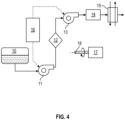
- FIG. 4 illustrates an example of a turbomachine which comprises a fuel supply line composed here of a fuel tank 10, a low pressure pump 11, a filter 12, a high pressure pump 13, a metering device 14 and an oil/fuel heat exchanger 15.
- the turbomachine also comprises an accessory box 17 (“gear box”) to which is connected a drive shaft 18 intended to deliver mechanical power in the turbomachine.
- the low pressure pump 11 consists of an electromagnetic pump, for example of the liquid ring type or of the side channel or regenerative type or of the volumetric gear type as described previously in the case of a drive by an electric machine.
- the low pressure pump 11 is mechanically decoupled from the motor shaft 18 and is controlled independently, for example by the digital computer 16 integrated into the control device of the turbomachine.
- the low and/or high pressure supply pumps can also be replaced in part or in full by electromagnetic pumps controlled independently of the engine speed.
- gerotor type pumps are preferably but not exclusively used.
Landscapes
- Engineering & Computer Science (AREA)
- Mechanical Engineering (AREA)
- General Engineering & Computer Science (AREA)
- Chemical & Material Sciences (AREA)
- Combustion & Propulsion (AREA)
- Physics & Mathematics (AREA)
- Electromagnetism (AREA)
- Structures Of Non-Positive Displacement Pumps (AREA)
Description
- La présente invention concerne le domaine des turbomachines du type comprenant un corps rotatif comprenant un arbre moteur délivrant une puissance mécanique et au moins une pompe à entrainement magnétique.
- L'invention s'applique à tout type de turbomachines, en particulier celles utilisées dans les aéronefs comme les turboréacteurs, turbopropulseurs, et turbomachines à soufflantes non carénées, aussi connues sous le vocable anglo-saxon de « Open Rotor ».
- L'arrière-plan technique comprend notamment le document
FR3102510 A1 - Une turbomachine conventionnelle comporte de manière connue un ou plusieurs corps rotatifs. Chaque corps rotatif comprend un compresseur, une turbine et un arbre moteur reliant la turbine au compresseur pour entraîner le compresseur en rotation. Une partie de la puissance générée par la turbomachine est utilisée pour entraîner différents accessoires (ou machines auxiliaires), nécessaires au fonctionnement du turboréacteur ou de l'aéronef, tels que par exemple une pompe de lubrification ou une pompe à carburant.
- A cet effet, la turbomachine comprend généralement une boîte d'engrenage d'accessoires (également connue « Accessory Gear Box » en anglais) reliant l'arbre moteur aux pompes. Lorsque l'arbre moteur est entraîné en rotation, la boîte d'engrenage d'accessoires transmet le mouvement de rotation aux différents accessoires. En d'autres termes, l'énergie mécanique produite par l'arbre moteur est transmise aux pompes par la boîte d'engrenage d'accessoires.
- Cette solution technique présente toutefois les inconvénients suivants :
- une partie de la puissance mécanique délivrée par le corps rotatif est prélevée pour entraîner la ou les pompes,
- la vitesse de rotation de la ou des pompes est dépendante de la vitesse de rotation de l'arbre moteur, la ou les pompes ne pouvant alors pas être pilotées selon un régime moteur indépendant,
- la liaison mécanique entre l'arbre moteur et la ou les pompes nécessite des étanchéités dynamiques qui sont difficiles à réaliser et s'usent au cours du temps,
- la ou les pompes comportent un arbre de rotation supporté par des paliers mécaniques soumis aux usures mécaniques liées aux frottements qui diminuent fortement le rendement de la ou des pompes.
- la liaison mécanique entre l'arbre moteur et la ou les pompes requiert de placer la ou les pompes au voisinage de la boîte d'engrenage d'accessoires, ce qui limite grandement les possibilités d'implantation de la ou des pompes dans une turbomachine et la soumet à des contraintes thermiques.
- La présente invention a pour but de remédier à au moins une partie de ces inconvénients et de proposer une turbomachine comportant une pompe découplée mécaniquement de l'arbre moteur et dans laquelle les contacts physiques entre le rotor de la pompe et le reste de la pompe sont éliminés.
- À cet effet, l'invention concerne une turbomachine comprenant un corps rotatif comportant un arbre moteur délivrant une puissance mécanique, et au moins une pompe à entrainement magnétique comprenant au moins :
- un stator délimitant un volume interne annulaire et comportant un premier et un second flasques,
- un rotor agencé dans le volume interne entre les premier et second flasques et apte à entraîner un fluide, le rotor étant mobile en rotation autour d'un axe de rotation,
- une paire d'aimants de polarités opposées agencée sur le rotor de manière coaxiale avec l'axe de rotation,
- un aimant agencé sur le premier flasque pour coopérer avec un des aimants de la paire d'aimants du rotor,
- un moyen d'entrainement magnétique du rotor en rotation distant du rotor par le second flasque, le second flasque étant amagnétique.
- La turbomachine selon l'invention est ainsi équipée d'une ou plusieurs pompes qui peuvent soit être découplées mécaniquement de l'arbre moteur et alors pilotables indépendamment du régime moteur, soit couplées magnétiquement à l'arbre moteur. Il est ainsi possible d'avoir une plus grande liberté sur le choix de la vitesse de rotation de la pompe et sur les possibilités d'implantation de la ou les pompes dans la turbomachine. En effet, la pompe est entrainée en rotation par un entrainement magnétique au lieu d'un arbre mécanique.
- En outre, les paliers mécaniques de l'art antérieur sont remplacés par un palier « magnétique » formé par les aimants agencés sur le rotor et le stator coaxialement avec l'axe de rotation du rotor, éliminant ainsi les contacts physiques entre le rotor et le reste de la pompe.
- Ainsi, les aimants de la pompe permettent à la fois de réaliser l'entraînement en rotation du rotor de la pompe et de réaliser un calage du rotor dans la pompe axial magnétiquement et radial par le champ magnétique.
- Selon une caractéristique particulière de l'invention, le moyen d'entraînement magnétique comporte un arbre couplé mécaniquement avec l'arbre moteur du corps rotatif de la turbomachine ou avec l'arbre moteur d'une machine électrique et un couple d'aimants de polarités opposées agencée de manière coaxiale avec l'axe de rotation et solidaire de l'arbre, et le second flasque comporte un palier logeant ledit couple d'aimants du moyen d'entraînement magnétique.
- Le rotor de la pompe peut ainsi être entrainé par le moyen d'entraînement de la même manière que dans un coupleur magnétique par la rotation de l'arbre externe sans contact entre eux par un accouplement à flux axial entre les aimants du rotor et les aimants du moyen d'entrainement.
- Avantageusement, les aimants de la paire d'aimants agencée sur le rotor, l'aimant agencé sur le premier flasque et les aimants du moyen d'entraînement magnétique sont des aimants permanents.
- Selon une caractéristique particulière de l'invention, les aimants de la paire d'aimants agencée sur le rotor, l'aimant agencé sur le premier flasque et les aimants du moyen d'entraînement magnétique forment une rangée d'aimants de polarités alternées.
- De préférence, la ou les pompes à entrainement magnétique sont du type à anneau liquide, à canal latéral ou gérotor.
- Selon une autre caractéristique particulière, au moins une des pompes est agencée et configurée pour alimenter la turbomachine en carburant ou en lubrifiant ou réaliser un transfert de carburant entre des compartiments d'un réservoir d'une turbomachine ou réaliser la mise en pression d'un compresseur air ou pour être utilisée dans un système de dégivrage sans prélèvement.
- L'invention a encore pour objet un aéronef comprenant au moins un turbopropulseur ou un turboréacteur comprenant une turbomachine selon l'invention.
- La présente invention sera mieux comprise et d'autres détails, caractéristiques et avantages de la présente invention apparaîtront plus clairement à la lecture de la description d'un exemple non limitatif qui suit, en référence aux dessins annexés sur lesquels :
- La
figure 1 est une vue schématique en perspective éclatée d'une pompe électromagnétique conformément à un mode de réalisation de l'invention, - La
figure 2 est une vue schématique en coupe selon l'axe longitudinal de la pompe électromagnétique de lafigure 1 , - La
figure 3 est une vue schématique en coupe selon l'axe longitudinal de la pompe électromagnétique de lafigure 1 selon une variante, et - La
figure 4 est une représentation schématique d'une turbomachine selon l'invention. - Les éléments ayant les mêmes fonctions dans les différentes mises en œuvre ont les mêmes références dans les figures.
- L'invention s'applique d'une manière générale à toute turbomachine équipée d'au moins une pompe pilotée indépendamment du régime moteur de la turbomachine. Elle s'applique notamment, mais pas exclusivement, aux pompes du type à anneau liquide, à canal latéral ou régénérative et gérotor. De même, l'invention peut s'appliquer aux pompes centrifuges ou volumétriques à engrenages.
- Les
figures 1 et2 illustrent une pompe électromagnétique 100 conformément à un mode de réalisation de l'invention. Dans l'exemple décrit ici, la pompe électromagnétique 100 est une pompe du type à anneau liquide comprenant un corps de pompe fixe ou stator 110 délimitant un volume interne annulaire et comprenant un premier demi-carter 111 et un deuxième demi-carter 112. Le premier demi-carter 111 comporte une partie centrale cylindrique pleine 1110, formant un premier flasque, et une paroi externe circulaire 1112 s'étendant concentriquement autour de la partie centrale 1110. Le premier flasque 1110 est muni d'un port d'aspiration ou de refoulement 1111. - De même, le deuxième demi-carter 112 comporte une partie centrale cylindrique pleine 1120, formant un deuxième flasque, et une paroi externe circulaire 1122 s'étendant concentriquement autour de la partie centrale 1120. Le deuxième flasque 1120 comporte un port de refoulement ou d'aspiration 1121. Le deuxième flasque 1120 est amagnétique.
- En outre, la pompe électromagnétique 100 comprend une roue à aubes 120, également appelée rotor ou rouet, agencée dans le volume interne entre les deux flasques du stator et apte à entraîner un fluide. Le rotor 120 est mobile en rotation autour d'un axe de rotation A suivant une direction axiale DA et comprend une roue 121 muni d'une pluralité d'aubes 122 s'étendant depuis la roue suivant une direction radiale DR.
- La roue à aubes 120 comporte un arbre magnétique de rotation 124 s'étendant suivant la direction axiale DA, formé d'une paire d'aimants, de préférence permanents, de polarités opposées agencée sur la roue à aubes 120 du rotor de manière coaxiale avec l'axe de rotation A. Dans l'exemple décrit ici, la paire d'aimants comporte deux pastilles aimantées s'étendant le long de l'axe de rotation suivant la direction axiale DA, l'une 1241 de pôle sud et l'autre 1242 de pôle nord. Par pastille aimantée, on entend un aimant de forme cylindrique dont l'axe est suivant la direction axiale DA. A cet effet, la roue à aubes 120 comporte un orifice traversant s'étendant le long de l'axe de rotation A dans lequel est logée la paire d'aimants 1241, 1242.
- De plus, le premier flasque 1110 comporte une cavité cylindrique s'étendant le long de l'axe de rotation A logeant un aimant 1116, de préférence permanent et en forme de pastille aimantée. L'aimant 1116 du premier flasque 1110 est agencé coaxialement avec l'axe de rotation A et donc avec la paire d'aimants 1241, 1242 du rotor. Il est adapté pour coopérer avec un des aimants du rotor arrangé en face de lui. En d'autres termes, l'aimant 1116 du premier flasque 1110 est agencé en vis-à-vis de l'aimant 1241 et a une polarité opposée à celle de celui-ci. Ainsi, dans l'exemple décrit ici, l'aimant 1116 a un pôle nord puisque l'aimant 1241 du rotor agencé en regard a un pôle sud.
- En outre, la pompe à entrainement magnétique 100 comporte un moyen d'entrainement magnétique 130 du rotor en rotation sans contact. Le moyen d'entrainement magnétique 130 est agencé sur le second flasque 112. Le moyen d'entrainement magnétique 130 est distant du rotor 120 notamment par le second flasque amagnétique 112. Il comporte un arbre 131 couplé mécaniquement avec l'arbre moteur du corps rotatif de la turbomachine ou d'une machine électrique et un couple d'aimants, de préférence permanents, de polarités opposées agencé de manière coaxiale avec l'axe de rotation A et solidaire de l'arbre 131, par exemple par collage. Dans l'exemple décrit ici, le couple d'aimants comporte deux pastilles aimantées s'étendant le long de l'axe de rotation suivant la direction axiale DA, l'une 1321 de pôle sud et l'autre 1322 de pôle nord. A cet effet, le second flasque 1120 comporte un palier 133 logeant ledit couple d'aimants du moyen d'entraînement magnétique. Le palier s'étend depuis une face externe du second flasque, c'est-à-dire opposée à une face interne du second flasque agencée en regard du rotor.
- Ainsi, les aimants 1241, 1242 de la paire d'aimants agencée sur le rotor, l'aimant 1116 agencé sur le premier flasque et les aimants 1321, 1322 du moyen d'entraînement magnétique 130 sont coaxiaux et forment une rangée d'aimants de polarités alternées. L'aimant 1116 du premier flasque et les aimants 1321, 1322 du moyen d'entraînement magnétique 130 jouent le rôle de palier magnétique pour l'arbre magnétique de rotation 124 du rotor et remplacent ainsi avantageusement les paliers mécaniques de l'art antérieur. En effet, ils permettent de caler axialement le rotor, de façon magnétique et de manière passive, c'est-à-dire sans contact physique entre le rotor et le reste de la pompe. Ils permettent également de caler radialement le rotor par les champs magnétiques induits.
- Le rotor de la pompe peut ainsi être entrainé par le moyen d'entraînement 130 de la même manière que dans un coupleur magnétique par la rotation de l'arbre externe 131 sans contact entre eux par un accouplement à flux axial entre les aimants 1241, 1242 du rotor et les aimants 1321, 1322 du moyen d'entrainement 130.
- Selon une alternative illustrée sur la
figure 3 , l'aimant 1116 du premier flasque 1110 est agencé en vis-à-vis de l'aimant 1242 du rotor et sont de même polarité, ici un pôle nord. L'autre aimant 1241 de la paire d'aimants du rotor est agencé en vis-à-vis de l'aimant 1321 du moyen d'entraînement magnétique 130 et sont de même polarité, ici un pôle sud. - Selon un autre mode de réalisation non illustré, les aimants du rotor sont formés d'un arrangement de pastilles aimantées de même polarité formant des disques aimantés et les aimants du moyen d'entraînement magnétique sont formés d'un arrangement de pastilles aimantées de polarité opposée à celle du disque aimanté du rotor agencé en regard et formant également un disque aimanté. Le disque aimanté du rotor et le disque aimanté de l'entrainement magnétique sont disposés l'un en face de l'autre afin de permettre un couplage magnétique entre eux. Le nombre de pastilles aimantées et les dimensions correspondantes des disque aimantés du rotor et de l'entrainement magnétique sont choisis en fonction des besoins de puissance de calage axial et radial et de la puissance d'entrainement nécessaire.
- Une fois tous les éléments constitutifs de la pompe 100 assemblés, les aimants permanents 1241, 1242 se trouvent en vis-à-vis des aimants 1321, 1322 du moyen d'entrainement 130 suivant une direction radiale DR comme illustré sur les
figures 2 et3 . Le pilotage de la pompe électromagnétique 100 (couple et vitesse de rotation) est réalisé par contrôle du couple et de la vitesse de rotation de l'arbre du moyen d'entrainement 130. - De manière connue dans les pompes de type à anneau liquide, l'arbre est placé de façon excentrique sur la roue à aube 120 par exemple au moyen d'une entretoise (non représentée sur les
figures 1 et2 ) de manière à créer des variations de volume inter-aubes (ou inter-pales) qui permettent d'aspirer le fluide pompé, par exemple par le port 1111 puis de l'évacuer sous pression, par exemple par le port 1121. - La pompe 100 peut également être une pompe à canal latéral, encore appelée pompe régénérative. Dans ce cas et de façon connue, un canal latéral présent ici sur les demicarters 111 et 112 s'étend entre les ports 1111 et 1121. Seul le canal latéral 1115 sur le demi-carter 111 est illustré en pointillés sur la
figure 1 . L'évolution des variations de volume inter-aubes (ou inter-pales), associée au champ de vitesse (vortex) présent dans le canal latéral 1115, permet d'aspirer le fluide, par exemple par le port 1111, puis de l'évacuer sous pression, par exemple par le port 1121. - Bien que l'invention a été décrite pour des pompes du type à anneau liquide ou à canal latéral, celle-ci peut également s'appliquer par exemple à des pompes de type gérotor, centrifuges ou volumétriques à engrenages.
- Une pompe électromagnétique selon l'invention peut notamment être utilisée pour alimenter en carburant ou en lubrifiant la turbomachine ou réaliser un transfert de carburant entre des compartiments d'un réservoir d'une turbomachine.
- La
figure 4 illustre un exemple de turbomachine qui comporte une ligne d'alimentation en carburant composée ici d'un réservoir de carburant 10, d'une pompe basse pression 11, d'un filtre 12, d'une pompe haute pression 13, d'un dispositif de dosage 14 et d'un échangeur de chaleur huile/carburant 15. La turbomachine comprend également une boîte d'accessoires 17 (« gear box ») à laquelle est relié un arbre moteur 18 destiné à délivrer une puissance mécanique dans la turbomachine. Conformément à l'invention, la pompe basse pression 11 est constituée d'une pompe électromagnétique, par exemple du type à anneau liquide ou du type à canal latéral ou régénérative ou du type volumique à engrenages telles que décrites précédemment dans le cas d'un entrainement par une machine électrique. La pompe basse pression 11 est découplée mécaniquement de l'arbre moteur 18 et est pilotée de manière indépendante, par exemple par le calculateur numérique 16 intégré au dispositif de pilotage de la turbomachine. - Concernant le circuit d'alimentation en huile d'une turbomachine, les pompes d'alimentation basse et/ou haute pression peuvent être également remplacées en partie ou en totalité par des pompes électromagnétiques pilotées indépendamment du régime moteur. Dans ce cas, on utilise de préférence mais non exclusivement des pompes de type gérotor.
Claims (7)
- Turbomachine comprenant un corps rotatif comportant un arbre moteur délivrant une puissance mécanique, et au moins une pompe à entrainement magnétique comprenant au moins :- un stator (110) délimitant un volume interne annulaire et comportant un premier et un second flasques (1110, 1120),- un rotor (120) agencé dans le volume interne entre les premier et second flasques et apte à entraîner un fluide, le rotor étant mobile en rotation autour d'un axe de rotation (A),- une paire d'aimants (1241, 1242) de polarités opposées agencée sur le rotor de manière coaxiale avec l'axe de rotation,- un aimant (1116) agencé sur le premier flasque (1110) pour coopérer avec un des aimants de la paire d'aimants du rotor,- un moyen d'entrainement magnétique (130) du rotor en rotation agencé sur le second flasque (1120), le second flasque étant amagnétique.
- Turbomachine selon la revendication 1, dans laquelle le moyen d'entraînement magnétique (130) comporte un arbre (131) couplé mécaniquement avec l'arbre moteur du corps rotatif de la turbomachine et un couple d'aimants (1321, 1322) de polarités opposées agencée de manière coaxiale avec l'axe de rotation (A) et solidaire de l'arbre (131), et le second flasque comporte un palier (133) logeant ledit couple d'aimants du moyen d'entraînement magnétique.
- Turbomachine selon la revendication 2, dans laquelle les aimants (1241, 1242) de la paire d'aimants agencée sur le rotor, l'aimant (1116) agencé sur le premier flasque et les aimants (1321, 1322) du moyen d'entraînement magnétique sont des aimants permanents.
- Turbomachine selon l'une des revendications 2 à 3, dans laquelle les aimants (1241, 1242) de la paire d'aimants agencée sur le rotor, l'aimant (1116) agencé sur le premier flasque et les aimants (1321, 1322) du moyen d'entraînement magnétique forment une rangée d'aimants de polarités alternées.
- Turbomachine selon l'une quelconque des revendications précédentes, dans laquelle la pompe à entrainement magnétique est du type à anneau liquide, à canal latéral, gérotor, centrifuge ou volumétrique à engrenages.
- Turbomachine selon l'une quelconque des revendications précédentes, dans laquelle au moins une des pompes est agencée pour alimenter la turbomachine en carburant ou en lubrifiant.
- Aéronef comportant au moins une turbomachine selon l'une quelconque des revendications précédentes.
Applications Claiming Priority (2)
| Application Number | Priority Date | Filing Date | Title |
|---|---|---|---|
| FR2105859A FR3123688B1 (fr) | 2021-06-03 | 2021-06-03 | Turbomachine équipée d’une pompe à entrainement magnétique |
| PCT/FR2022/051038 WO2022254148A1 (fr) | 2021-06-03 | 2022-06-01 | Turbomachine équipée d'une pompe à entrainement magnétique |
Publications (2)
| Publication Number | Publication Date |
|---|---|
| EP4348018A1 EP4348018A1 (fr) | 2024-04-10 |
| EP4348018B1 true EP4348018B1 (fr) | 2025-03-19 |
Family
ID=76523205
Family Applications (1)
| Application Number | Title | Priority Date | Filing Date |
|---|---|---|---|
| EP22734659.0A Active EP4348018B1 (fr) | 2021-06-03 | 2022-06-01 | Turbomachine équipée d'une pompe a entraînement magnétique |
Country Status (5)
| Country | Link |
|---|---|
| US (1) | US12442385B2 (fr) |
| EP (1) | EP4348018B1 (fr) |
| CN (1) | CN117425770A (fr) |
| FR (1) | FR3123688B1 (fr) |
| WO (1) | WO2022254148A1 (fr) |
Family Cites Families (21)
| Publication number | Priority date | Publication date | Assignee | Title |
|---|---|---|---|---|
| DE2834735A1 (de) * | 1978-08-08 | 1980-02-14 | Buehl Volks Raiffeisenbank | Fluessigkeitspumpe, insbesondere fuer fluessigkeiten geringer viskositaet, wie wasser, alkohole u.a. |
| US5145329A (en) * | 1990-06-29 | 1992-09-08 | Eaton Corporation | Homoplanar brushless electric gerotor |
| US5713730A (en) * | 1992-09-04 | 1998-02-03 | Kyocera Corporation | Ceramic pivot bearing arrangement for a sealless blood pump |
| US5725357A (en) * | 1995-04-03 | 1998-03-10 | Ntn Corporation | Magnetically suspended type pump |
| USH1966H1 (en) * | 1997-08-28 | 2001-06-05 | The United States Of America As Represented By The Secretary Of The Navy | Integrated motor/gear pump |
| US6641378B2 (en) * | 2001-11-13 | 2003-11-04 | William D. Davis | Pump with electrodynamically supported impeller |
| US6881033B2 (en) * | 2002-09-30 | 2005-04-19 | Fisher & Paykel Healthcare Limited | Impeller |
| US8632449B2 (en) * | 2009-04-16 | 2014-01-21 | Bivacor Pty Ltd | Heart pump controller |
| US8636638B2 (en) * | 2009-04-16 | 2014-01-28 | Bivacor Pty Ltd | Heart pump controller |
| CN102667167A (zh) * | 2010-02-02 | 2012-09-12 | 三菱重工业株式会社 | 离心泵 |
| KR101237023B1 (ko) * | 2010-05-19 | 2013-02-25 | 주식회사 아모텍 | 완전 방수구조를 갖는 유체 펌프 |
| US9667117B2 (en) * | 2012-07-30 | 2017-05-30 | Chakratec Ltd. | Magnetically coupled flywheel |
| US9127680B2 (en) * | 2013-04-05 | 2015-09-08 | Thoratec Corporation | Verification of magnetic balance for magnetically levitated impeller |
| WO2016130944A1 (fr) * | 2015-02-12 | 2016-08-18 | Thoratec Corporation | Système et procédé de commande de la position d'un rotor en lévitation |
| DE102017222754A1 (de) * | 2017-12-14 | 2019-06-19 | Magna Powertrain Bad Homburg GmbH | Gerotor Pumpe |
| KR102665157B1 (ko) * | 2018-02-14 | 2024-05-10 | 스택폴 인터내셔널 엔지니어드 프로덕츠, 엘티디. | 스핀들을 구비한 지로터 |
| EP3581216A1 (fr) * | 2018-06-11 | 2019-12-18 | Universität Zürich | Pompe sanguine pour l'assistance circulatoire mécanique des patients opérés d'un fontan |
| US11168690B2 (en) * | 2019-04-11 | 2021-11-09 | Schaeffler Technologies AG & Co. KG | Integrated motor and pump including axially placed coils |
| FR3102510B1 (fr) | 2019-10-25 | 2021-11-12 | Safran Helicopter Engines | Turbomachine munie d’une pompe électromagnétique à flux magnétique axial |
| FR3106625B1 (fr) * | 2020-01-27 | 2022-11-04 | Safran Helicopter Engines | Circuit d’alimentation en carburant d’un moteur d’aéronef |
| US12015320B2 (en) * | 2020-05-07 | 2024-06-18 | Agilent Technologies, Inc. | Air gap magnetic coupling with counterbalanced force |
-
2021
- 2021-06-03 FR FR2105859A patent/FR3123688B1/fr active Active
-
2022
- 2022-06-01 WO PCT/FR2022/051038 patent/WO2022254148A1/fr not_active Ceased
- 2022-06-01 EP EP22734659.0A patent/EP4348018B1/fr active Active
- 2022-06-01 US US18/565,441 patent/US12442385B2/en active Active
- 2022-06-01 CN CN202280039084.2A patent/CN117425770A/zh active Pending
Also Published As
| Publication number | Publication date |
|---|---|
| US12442385B2 (en) | 2025-10-14 |
| FR3123688B1 (fr) | 2023-05-26 |
| CN117425770A (zh) | 2024-01-19 |
| EP4348018A1 (fr) | 2024-04-10 |
| WO2022254148A1 (fr) | 2022-12-08 |
| US20240141911A1 (en) | 2024-05-02 |
| FR3123688A1 (fr) | 2022-12-09 |
Similar Documents
| Publication | Publication Date | Title |
|---|---|---|
| EP0664410A1 (fr) | Palier magnétique et ensemble comportant une partie statorique et une partie rotorique suspendue par un tel palier | |
| EP4097343B1 (fr) | Circuit d'alimentation en carburant d'un moteur d'aeronef | |
| US5253986A (en) | Impeller-type pump system | |
| EP4048897B1 (fr) | Turbomachine munie d'une pompe electromagnetique a flux magnetique axial | |
| EP4348018B1 (fr) | Turbomachine équipée d'une pompe a entraînement magnétique | |
| EP3973158A1 (fr) | Agencement de turbomachines d'aeronautique comprenant une pompe de lubrification entrainee par deux engrenages obliques | |
| EP4508336A1 (fr) | Module pour une turbomachine d'aeronef | |
| FR3060896B1 (fr) | Compresseur electrique avec circuit de refroidissement | |
| FR3102509A1 (fr) | Turbomachine munie d’une pompe électromagnétique à flux magnétique radial | |
| FR3123694A1 (fr) | Pompe electromagnétique pour turbomachine | |
| EP4423368B1 (fr) | Assemblage pour turbogénérateur | |
| FR3112172A1 (fr) | Pompe à vide sèche | |
| BE1028023A1 (fr) | Ensemble de pompage | |
| EP3921922B1 (fr) | Dispositif de compression d'un fluide entraine par une machine electrique avec arbre de compression traversant le rotor | |
| FR3092617A1 (fr) | Ensemble comprenant un boitier d’accessoires pour une turbomachine | |
| EP3805583B1 (fr) | Moteur et/ou générateur pour un véhicule ferroviaire, bogie et véhicule ferroviaire associés | |
| FR3098258A1 (fr) | Pompe à engrenages basculante pour turbomachine, incorporable à un circuit de lubrification de moteur d’aéronef | |
| WO2025109269A1 (fr) | Reducteur pour un aeronef | |
| FR3112369A1 (fr) | Compresseur contrarotatif de turbomachine | |
| WO2025088266A1 (fr) | Transmission de puissance dans une turbomachine d'aeronef | |
| BE1031636A1 (fr) | Pompe a palettes radiales | |
| WO2025247911A1 (fr) | Dispositif de transfert fluidique multivoies à partie centrale comprenant deux corps concentriques solidarisés en rotation par des dents respectives | |
| FR3162951A1 (fr) | Ensemble de boitier d’entrainement d’accessoires et de génération électrique | |
| FR3162795A1 (fr) | Boitier d’accessoires pour une turbomachine d’aeronef | |
| WO2020160877A1 (fr) | Dispositif de compression d'un fluide entraine par une machine electrique avec rotor equipe d'un aimant cylindrique plein |
Legal Events
| Date | Code | Title | Description |
|---|---|---|---|
| STAA | Information on the status of an ep patent application or granted ep patent |
Free format text: STATUS: UNKNOWN |
|
| STAA | Information on the status of an ep patent application or granted ep patent |
Free format text: STATUS: THE INTERNATIONAL PUBLICATION HAS BEEN MADE |
|
| PUAI | Public reference made under article 153(3) epc to a published international application that has entered the european phase |
Free format text: ORIGINAL CODE: 0009012 |
|
| STAA | Information on the status of an ep patent application or granted ep patent |
Free format text: STATUS: REQUEST FOR EXAMINATION WAS MADE |
|
| 17P | Request for examination filed |
Effective date: 20231222 |
|
| AK | Designated contracting states |
Kind code of ref document: A1 Designated state(s): AL AT BE BG CH CY CZ DE DK EE ES FI FR GB GR HR HU IE IS IT LI LT LU LV MC MK MT NL NO PL PT RO RS SE SI SK SM TR |
|
| DAV | Request for validation of the european patent (deleted) | ||
| DAX | Request for extension of the european patent (deleted) | ||
| GRAP | Despatch of communication of intention to grant a patent |
Free format text: ORIGINAL CODE: EPIDOSNIGR1 |
|
| STAA | Information on the status of an ep patent application or granted ep patent |
Free format text: STATUS: GRANT OF PATENT IS INTENDED |
|
| INTG | Intention to grant announced |
Effective date: 20241209 |
|
| GRAS | Grant fee paid |
Free format text: ORIGINAL CODE: EPIDOSNIGR3 |
|
| GRAA | (expected) grant |
Free format text: ORIGINAL CODE: 0009210 |
|
| STAA | Information on the status of an ep patent application or granted ep patent |
Free format text: STATUS: THE PATENT HAS BEEN GRANTED |
|
| AK | Designated contracting states |
Kind code of ref document: B1 Designated state(s): AL AT BE BG CH CY CZ DE DK EE ES FI FR GB GR HR HU IE IS IT LI LT LU LV MC MK MT NL NO PL PT RO RS SE SI SK SM TR |
|
| REG | Reference to a national code |
Ref country code: GB Ref legal event code: FG4D Free format text: NOT ENGLISH |
|
| REG | Reference to a national code |
Ref country code: CH Ref legal event code: EP |
|
| REG | Reference to a national code |
Ref country code: DE Ref legal event code: R096 Ref document number: 602022012026 Country of ref document: DE |
|
| REG | Reference to a national code |
Ref country code: IE Ref legal event code: FG4D Free format text: LANGUAGE OF EP DOCUMENT: FRENCH |
|
| PG25 | Lapsed in a contracting state [announced via postgrant information from national office to epo] |
Ref country code: RS Free format text: LAPSE BECAUSE OF FAILURE TO SUBMIT A TRANSLATION OF THE DESCRIPTION OR TO PAY THE FEE WITHIN THE PRESCRIBED TIME-LIMIT Effective date: 20250619 |
|
| PG25 | Lapsed in a contracting state [announced via postgrant information from national office to epo] |
Ref country code: FI Free format text: LAPSE BECAUSE OF FAILURE TO SUBMIT A TRANSLATION OF THE DESCRIPTION OR TO PAY THE FEE WITHIN THE PRESCRIBED TIME-LIMIT Effective date: 20250319 |
|
| PGFP | Annual fee paid to national office [announced via postgrant information from national office to epo] |
Ref country code: DE Payment date: 20250618 Year of fee payment: 4 |
|
| REG | Reference to a national code |
Ref country code: LT Ref legal event code: MG9D |
|
| PG25 | Lapsed in a contracting state [announced via postgrant information from national office to epo] |
Ref country code: NO Free format text: LAPSE BECAUSE OF FAILURE TO SUBMIT A TRANSLATION OF THE DESCRIPTION OR TO PAY THE FEE WITHIN THE PRESCRIBED TIME-LIMIT Effective date: 20250619 |
|
| PG25 | Lapsed in a contracting state [announced via postgrant information from national office to epo] |
Ref country code: HR Free format text: LAPSE BECAUSE OF FAILURE TO SUBMIT A TRANSLATION OF THE DESCRIPTION OR TO PAY THE FEE WITHIN THE PRESCRIBED TIME-LIMIT Effective date: 20250319 |
|
| PG25 | Lapsed in a contracting state [announced via postgrant information from national office to epo] |
Ref country code: LV Free format text: LAPSE BECAUSE OF FAILURE TO SUBMIT A TRANSLATION OF THE DESCRIPTION OR TO PAY THE FEE WITHIN THE PRESCRIBED TIME-LIMIT Effective date: 20250319 |
|
| PGFP | Annual fee paid to national office [announced via postgrant information from national office to epo] |
Ref country code: FR Payment date: 20250620 Year of fee payment: 4 |
|
| PG25 | Lapsed in a contracting state [announced via postgrant information from national office to epo] |
Ref country code: BG Free format text: LAPSE BECAUSE OF FAILURE TO SUBMIT A TRANSLATION OF THE DESCRIPTION OR TO PAY THE FEE WITHIN THE PRESCRIBED TIME-LIMIT Effective date: 20250319 Ref country code: GR Free format text: LAPSE BECAUSE OF FAILURE TO SUBMIT A TRANSLATION OF THE DESCRIPTION OR TO PAY THE FEE WITHIN THE PRESCRIBED TIME-LIMIT Effective date: 20250620 |
|
| REG | Reference to a national code |
Ref country code: NL Ref legal event code: MP Effective date: 20250319 |
|
| REG | Reference to a national code |
Ref country code: AT Ref legal event code: MK05 Ref document number: 1777125 Country of ref document: AT Kind code of ref document: T Effective date: 20250319 |
|
| PG25 | Lapsed in a contracting state [announced via postgrant information from national office to epo] |
Ref country code: NL Free format text: LAPSE BECAUSE OF FAILURE TO SUBMIT A TRANSLATION OF THE DESCRIPTION OR TO PAY THE FEE WITHIN THE PRESCRIBED TIME-LIMIT Effective date: 20250319 |
|
| PG25 | Lapsed in a contracting state [announced via postgrant information from national office to epo] |
Ref country code: SE Free format text: LAPSE BECAUSE OF FAILURE TO SUBMIT A TRANSLATION OF THE DESCRIPTION OR TO PAY THE FEE WITHIN THE PRESCRIBED TIME-LIMIT Effective date: 20250319 |
|
| PG25 | Lapsed in a contracting state [announced via postgrant information from national office to epo] |
Ref country code: SM Free format text: LAPSE BECAUSE OF FAILURE TO SUBMIT A TRANSLATION OF THE DESCRIPTION OR TO PAY THE FEE WITHIN THE PRESCRIBED TIME-LIMIT Effective date: 20250319 |
|
| PG25 | Lapsed in a contracting state [announced via postgrant information from national office to epo] |
Ref country code: ES Free format text: LAPSE BECAUSE OF FAILURE TO SUBMIT A TRANSLATION OF THE DESCRIPTION OR TO PAY THE FEE WITHIN THE PRESCRIBED TIME-LIMIT Effective date: 20250319 Ref country code: PT Free format text: LAPSE BECAUSE OF FAILURE TO SUBMIT A TRANSLATION OF THE DESCRIPTION OR TO PAY THE FEE WITHIN THE PRESCRIBED TIME-LIMIT Effective date: 20250721 |
|
| PG25 | Lapsed in a contracting state [announced via postgrant information from national office to epo] |
Ref country code: PL Free format text: LAPSE BECAUSE OF FAILURE TO SUBMIT A TRANSLATION OF THE DESCRIPTION OR TO PAY THE FEE WITHIN THE PRESCRIBED TIME-LIMIT Effective date: 20250319 |
|
| PGFP | Annual fee paid to national office [announced via postgrant information from national office to epo] |
Ref country code: IT Payment date: 20250630 Year of fee payment: 4 |
|
| PG25 | Lapsed in a contracting state [announced via postgrant information from national office to epo] |
Ref country code: AT Free format text: LAPSE BECAUSE OF FAILURE TO SUBMIT A TRANSLATION OF THE DESCRIPTION OR TO PAY THE FEE WITHIN THE PRESCRIBED TIME-LIMIT Effective date: 20250319 |
|
| PG25 | Lapsed in a contracting state [announced via postgrant information from national office to epo] |
Ref country code: EE Free format text: LAPSE BECAUSE OF FAILURE TO SUBMIT A TRANSLATION OF THE DESCRIPTION OR TO PAY THE FEE WITHIN THE PRESCRIBED TIME-LIMIT Effective date: 20250319 Ref country code: CZ Free format text: LAPSE BECAUSE OF FAILURE TO SUBMIT A TRANSLATION OF THE DESCRIPTION OR TO PAY THE FEE WITHIN THE PRESCRIBED TIME-LIMIT Effective date: 20250319 |
|
| PG25 | Lapsed in a contracting state [announced via postgrant information from national office to epo] |
Ref country code: RO Free format text: LAPSE BECAUSE OF FAILURE TO SUBMIT A TRANSLATION OF THE DESCRIPTION OR TO PAY THE FEE WITHIN THE PRESCRIBED TIME-LIMIT Effective date: 20250319 |
|
| PG25 | Lapsed in a contracting state [announced via postgrant information from national office to epo] |
Ref country code: SK Free format text: LAPSE BECAUSE OF FAILURE TO SUBMIT A TRANSLATION OF THE DESCRIPTION OR TO PAY THE FEE WITHIN THE PRESCRIBED TIME-LIMIT Effective date: 20250319 |
|
| PG25 | Lapsed in a contracting state [announced via postgrant information from national office to epo] |
Ref country code: IS Free format text: LAPSE BECAUSE OF FAILURE TO SUBMIT A TRANSLATION OF THE DESCRIPTION OR TO PAY THE FEE WITHIN THE PRESCRIBED TIME-LIMIT Effective date: 20250719 |
|
| REG | Reference to a national code |
Ref country code: DE Ref legal event code: R097 Ref document number: 602022012026 Country of ref document: DE |
|
| PG25 | Lapsed in a contracting state [announced via postgrant information from national office to epo] |
Ref country code: DK Free format text: LAPSE BECAUSE OF FAILURE TO SUBMIT A TRANSLATION OF THE DESCRIPTION OR TO PAY THE FEE WITHIN THE PRESCRIBED TIME-LIMIT Effective date: 20250319 |
|
| PLBE | No opposition filed within time limit |
Free format text: ORIGINAL CODE: 0009261 |
|
| STAA | Information on the status of an ep patent application or granted ep patent |
Free format text: STATUS: NO OPPOSITION FILED WITHIN TIME LIMIT |
|
| REG | Reference to a national code |
Ref country code: CH Ref legal event code: H13 Free format text: ST27 STATUS EVENT CODE: U-0-0-H10-H13 (AS PROVIDED BY THE NATIONAL OFFICE) Effective date: 20260127 |
|
| REG | Reference to a national code |
Ref country code: CH Ref legal event code: L10 Free format text: ST27 STATUS EVENT CODE: U-0-0-L10-L00 (AS PROVIDED BY THE NATIONAL OFFICE) Effective date: 20260128 |
|
| PG25 | Lapsed in a contracting state [announced via postgrant information from national office to epo] |
Ref country code: MC Free format text: LAPSE BECAUSE OF FAILURE TO SUBMIT A TRANSLATION OF THE DESCRIPTION OR TO PAY THE FEE WITHIN THE PRESCRIBED TIME-LIMIT Effective date: 20250319 |
|
| PG25 | Lapsed in a contracting state [announced via postgrant information from national office to epo] |
Ref country code: LU Free format text: LAPSE BECAUSE OF NON-PAYMENT OF DUE FEES Effective date: 20250601 |
|
| 26N | No opposition filed |
Effective date: 20251222 |
|
| REG | Reference to a national code |
Ref country code: BE Ref legal event code: MM Effective date: 20250630 |
|
| PG25 | Lapsed in a contracting state [announced via postgrant information from national office to epo] |
Ref country code: IE Free format text: LAPSE BECAUSE OF NON-PAYMENT OF DUE FEES Effective date: 20250601 |
|
| PG25 | Lapsed in a contracting state [announced via postgrant information from national office to epo] |
Ref country code: BE Free format text: LAPSE BECAUSE OF NON-PAYMENT OF DUE FEES Effective date: 20250630 |
|
| PG25 | Lapsed in a contracting state [announced via postgrant information from national office to epo] |
Ref country code: CH Free format text: LAPSE BECAUSE OF NON-PAYMENT OF DUE FEES Effective date: 20250630 |