EP4348012B1 - Turbomaschine mit integrierter elektrischer maschine im hinteren bereich - Google Patents
Turbomaschine mit integrierter elektrischer maschine im hinteren bereich Download PDFInfo
- Publication number
- EP4348012B1 EP4348012B1 EP22731746.8A EP22731746A EP4348012B1 EP 4348012 B1 EP4348012 B1 EP 4348012B1 EP 22731746 A EP22731746 A EP 22731746A EP 4348012 B1 EP4348012 B1 EP 4348012B1
- Authority
- EP
- European Patent Office
- Prior art keywords
- turbomachine
- stator
- low
- sleeve
- pressure shaft
- Prior art date
- Legal status (The legal status is an assumption and is not a legal conclusion. Google has not performed a legal analysis and makes no representation as to the accuracy of the status listed.)
- Active
Links
Images


Classifications
-
- F—MECHANICAL ENGINEERING; LIGHTING; HEATING; WEAPONS; BLASTING
- F01—MACHINES OR ENGINES IN GENERAL; ENGINE PLANTS IN GENERAL; STEAM ENGINES
- F01D—NON-POSITIVE DISPLACEMENT MACHINES OR ENGINES, e.g. STEAM TURBINES
- F01D15/00—Adaptations of machines or engines for special use; Combinations of engines with devices driven thereby
- F01D15/10—Adaptations for driving, or combinations with, electric generators
-
- F—MECHANICAL ENGINEERING; LIGHTING; HEATING; WEAPONS; BLASTING
- F01—MACHINES OR ENGINES IN GENERAL; ENGINE PLANTS IN GENERAL; STEAM ENGINES
- F01D—NON-POSITIVE DISPLACEMENT MACHINES OR ENGINES, e.g. STEAM TURBINES
- F01D25/00—Component parts, details, or accessories, not provided for in, or of interest apart from, other groups
- F01D25/16—Arrangement of bearings; Supporting or mounting bearings in casings
-
- F—MECHANICAL ENGINEERING; LIGHTING; HEATING; WEAPONS; BLASTING
- F01—MACHINES OR ENGINES IN GENERAL; ENGINE PLANTS IN GENERAL; STEAM ENGINES
- F01D—NON-POSITIVE DISPLACEMENT MACHINES OR ENGINES, e.g. STEAM TURBINES
- F01D25/00—Component parts, details, or accessories, not provided for in, or of interest apart from, other groups
- F01D25/18—Lubricating arrangements
-
- F—MECHANICAL ENGINEERING; LIGHTING; HEATING; WEAPONS; BLASTING
- F01—MACHINES OR ENGINES IN GENERAL; ENGINE PLANTS IN GENERAL; STEAM ENGINES
- F01D—NON-POSITIVE DISPLACEMENT MACHINES OR ENGINES, e.g. STEAM TURBINES
- F01D25/00—Component parts, details, or accessories, not provided for in, or of interest apart from, other groups
- F01D25/30—Exhaust heads, chambers, or the like
-
- F—MECHANICAL ENGINEERING; LIGHTING; HEATING; WEAPONS; BLASTING
- F02—COMBUSTION ENGINES; HOT-GAS OR COMBUSTION-PRODUCT ENGINE PLANTS
- F02C—GAS-TURBINE PLANTS; AIR INTAKES FOR JET-PROPULSION PLANTS; CONTROLLING FUEL SUPPLY IN AIR-BREATHING JET-PROPULSION PLANTS
- F02C7/00—Features, components parts, details or accessories, not provided for in, or of interest apart form groups F02C1/00 - F02C6/00; Air intakes for jet-propulsion plants
- F02C7/06—Arrangements of bearings; Lubricating
-
- F—MECHANICAL ENGINEERING; LIGHTING; HEATING; WEAPONS; BLASTING
- F02—COMBUSTION ENGINES; HOT-GAS OR COMBUSTION-PRODUCT ENGINE PLANTS
- F02C—GAS-TURBINE PLANTS; AIR INTAKES FOR JET-PROPULSION PLANTS; CONTROLLING FUEL SUPPLY IN AIR-BREATHING JET-PROPULSION PLANTS
- F02C7/00—Features, components parts, details or accessories, not provided for in, or of interest apart form groups F02C1/00 - F02C6/00; Air intakes for jet-propulsion plants
- F02C7/32—Arrangement, mounting, or driving, of auxiliaries
-
- F—MECHANICAL ENGINEERING; LIGHTING; HEATING; WEAPONS; BLASTING
- F02—COMBUSTION ENGINES; HOT-GAS OR COMBUSTION-PRODUCT ENGINE PLANTS
- F02C—GAS-TURBINE PLANTS; AIR INTAKES FOR JET-PROPULSION PLANTS; CONTROLLING FUEL SUPPLY IN AIR-BREATHING JET-PROPULSION PLANTS
- F02C7/00—Features, components parts, details or accessories, not provided for in, or of interest apart form groups F02C1/00 - F02C6/00; Air intakes for jet-propulsion plants
- F02C7/36—Power transmission arrangements between the different shafts of the gas turbine plant, or between the gas-turbine plant and the power user
-
- H—ELECTRICITY
- H02—GENERATION; CONVERSION OR DISTRIBUTION OF ELECTRIC POWER
- H02K—DYNAMO-ELECTRIC MACHINES
- H02K1/00—Details of the magnetic circuit
- H02K1/06—Details of the magnetic circuit characterised by the shape, form or construction
- H02K1/12—Stationary parts of the magnetic circuit
- H02K1/18—Means for mounting or fastening magnetic stationary parts on to, or to, the stator structures
- H02K1/185—Means for mounting or fastening magnetic stationary parts on to, or to, the stator structures to outer stators
-
- H—ELECTRICITY
- H02—GENERATION; CONVERSION OR DISTRIBUTION OF ELECTRIC POWER
- H02K—DYNAMO-ELECTRIC MACHINES
- H02K1/00—Details of the magnetic circuit
- H02K1/06—Details of the magnetic circuit characterised by the shape, form or construction
- H02K1/22—Rotating parts of the magnetic circuit
- H02K1/28—Means for mounting or fastening rotating magnetic parts on to, or to, the rotor structures
- H02K1/30—Means for mounting or fastening rotating magnetic parts on to, or to, the rotor structures using intermediate parts, e.g. spiders
-
- H—ELECTRICITY
- H02—GENERATION; CONVERSION OR DISTRIBUTION OF ELECTRIC POWER
- H02K—DYNAMO-ELECTRIC MACHINES
- H02K7/00—Arrangements for handling mechanical energy structurally associated with dynamo-electric machines, e.g. structural association with mechanical driving motors or auxiliary dynamo-electric machines
- H02K7/08—Structural association with bearings
- H02K7/083—Structural association with bearings radially supporting the rotary shaft at both ends of the rotor
-
- H—ELECTRICITY
- H02—GENERATION; CONVERSION OR DISTRIBUTION OF ELECTRIC POWER
- H02K—DYNAMO-ELECTRIC MACHINES
- H02K7/00—Arrangements for handling mechanical energy structurally associated with dynamo-electric machines, e.g. structural association with mechanical driving motors or auxiliary dynamo-electric machines
- H02K7/18—Structural association of electric generators with mechanical driving motors, e.g. with turbines
- H02K7/1807—Rotary generators
- H02K7/1823—Rotary generators structurally associated with turbines or similar engines
-
- H—ELECTRICITY
- H02—GENERATION; CONVERSION OR DISTRIBUTION OF ELECTRIC POWER
- H02K—DYNAMO-ELECTRIC MACHINES
- H02K9/00—Arrangements for cooling or ventilating
- H02K9/19—Arrangements for cooling or ventilating for machines with closed casing and closed-circuit cooling using a liquid cooling medium, e.g. oil
-
- F—MECHANICAL ENGINEERING; LIGHTING; HEATING; WEAPONS; BLASTING
- F05—INDEXING SCHEMES RELATING TO ENGINES OR PUMPS IN VARIOUS SUBCLASSES OF CLASSES F01-F04
- F05D—INDEXING SCHEME FOR ASPECTS RELATING TO NON-POSITIVE-DISPLACEMENT MACHINES OR ENGINES, GAS-TURBINES OR JET-PROPULSION PLANTS
- F05D2220/00—Application
- F05D2220/70—Application in combination with
- F05D2220/76—Application in combination with an electrical generator
- F05D2220/766—Application in combination with an electrical generator via a direct connection, i.e. a gearless transmission
-
- F—MECHANICAL ENGINEERING; LIGHTING; HEATING; WEAPONS; BLASTING
- F05—INDEXING SCHEMES RELATING TO ENGINES OR PUMPS IN VARIOUS SUBCLASSES OF CLASSES F01-F04
- F05D—INDEXING SCHEME FOR ASPECTS RELATING TO NON-POSITIVE-DISPLACEMENT MACHINES OR ENGINES, GAS-TURBINES OR JET-PROPULSION PLANTS
- F05D2260/00—Function
- F05D2260/40—Transmission of power
- F05D2260/403—Transmission of power through the shape of the drive components
Definitions
- the present invention relates to a turbomachine, in which an electric machine is integrated at the rear.
- This electric machine can be a pure electric generator, or a reversible machine that can also work as an electric motor; it is added to the electric machine traditionally placed on a gearbox at the periphery of the turbomachine to provide it and other aircraft equipment with the electrical energy they need.
- a turbomachine comprising an electric machine integrated at the rear, is described in the document FR 3 027 625 A1 .
- EP 3613977 A1 describes an electric machine at the rear of a turbomachine and detachable from the turbomachine by modules, which seems to make this document the closest to the invention.
- EP 3763929 A1 describes the mounting of an electric machine at the end of a high-pressure shaft of a turbomachine, in which the rotor of the electric machine is mounted on a sliding shaft end which extends the high-pressure shaft.
- FR 3073569 A1 describes an electric machine mounted on a propeller shaft of a turboprop, with a disengageable rotor.
- EP 3246528 A1 And EP 3708787 A1 describe other turbomachines equipped with electric machines.
- the rotor of the electric machine cannot in reality be mounted directly on the low pressure shaft, because it must be able to be decoupled from it in certain failure situations, for example short circuits, particularly in the case where the electric machine has permanent magnets. It is therefore necessary to add a decoupling device between the low pressure shaft and the rotor of the electric machine, and to support the rotor by independent bearings. The device is then made heavier, and the problems of layout and resistance to dynamic stresses risk becoming more acute. The additional bearings and the decoupling device must themselves withstand the high heat to which they are subjected.
- the invention encompasses several measures which make it possible, separately and in combination, to reduce or eliminate the difficulties mentioned above.
- the arrangement obtained at the rear of the turbomachine is relatively simple, compact, easily dismantled, and relatively undisturbing of the dynamic balances of the low-pressure shaft; excessive heating is finally little to fear.
- the invention thus relates to a turbomachine comprising a low-pressure shaft, extending along an axis of the turbomachine which defines a front and a rear; a turbomachine stator supporting the low-pressure shaft by bearings including a rear bearing; an electric machine located at a rear part of the turbomachine, and comprising a rotor driven in a disconnectable manner by the low-pressure shaft and a stator fixed to the stator of the turbomachine; comprising a support journal for the rotor of the electric machine, comprising a shaft section fixed in a releasable manner to a rear end of the low-pressure shaft by extending the low-pressure shaft, an armature to which the rotor of the electric machine is fixed and which surrounds the shaft section; characterized in that the stator of the electric machine surrounds the rotor of the electric machine; and in that the turbomachine further comprises at least one bearing mounted between the armature and the shaft section; and a
- a low pressure shaft a shaft associated with the rotation of a turbine at the very rear of the turbomachine, and which therefore extends further back than other possible shafts such as a high pressure shaft.
- the components of the electric machine can be placed in a cavity at the rear of the turbomachine, into which the end of the low-pressure shaft opens and which is closed at the rear by a conical cover.
- the bearing journal of the rotor of the turbomachine forms a unitary assembly which can be easily fixed to the end of the low-pressure shaft, and the stator of the machine can be fixed to the stator of the turbomachine, without almost modifying the design of existing turbomachines without the electric machine.
- the elongation of the low-pressure shaft due to the addition of the shaft section, and the rotor overhang, are moderate.
- the bearing or bearings integrated into the journal can easily be lubricated by a stand-alone device, separate from the lubrication devices dedicated to the support bearings of the low-pressure shaft and the high-pressure shaft, therefore without further modifying the existing lubrication circuits.
- the coupling sleeve removably connecting in rotation the low-pressure shaft and the rotor of the electric machine is compact and occupies, without difficulty in designing it, an empty volume still present around the end of the low-pressure shaft and behind the stator of the turbomachine. It is also easy to control, and does not introduce significant dynamic disturbances. And the disassembly of the various components (journal, coupling sleeve and stator of the electric machine) can be accomplished easily.
- bearing or bearings it is advantageous for the bearing or bearings to be lubricated with grease, by being contained in a closed lubrication enclosure.
- a dynamic lubrication, usual for turbomachines, by forced circulation of oil is in fact not necessary for these particular bearings, which are inactive in the usual state of driving the rotor of the electric machine, in which the coupling sleeve secures in rotation the armature with the low pressure shaft and the shaft section.
- a rotation between the armature and the shaft section exists only in the conditions of failures of the electric machine, during which a decoupling of the sleeve is ordered.
- Friction and heat are then produced by the bearings arranged between the shaft section and the rotor, but this state is generally brief, and the heat produced is then insufficient to produce significant damage. Such damage is likely to concern only the bearings, which can be easily replaced. And the surrounding heat, produced by the service of the turbomachine, is largely absorbed by the already existing fluid circulation cooling devices, which serve the parts near the journal: the heating it undergoes remains moderate even in the absence of a particular cooling device.
- the enclosure can be supplied with grease whatever the circumstances: it is then recommended that the shaft section be hollow and contain a grease reservoir which communicates with the enclosure by at least one hole.
- the grease in the reservoir can also help to lubricate the coupling devices between the sleeve on the one hand, and the armature, the low-pressure shaft or the shaft section on the other.
- the lubrication enclosure is then partly delimited by these parts.
- the coupling devices may be networks of radially or axially oriented grooves, depending on whether the connection between the parts they connect is to be interrupted or maintained during their axial movements from one state to another.
- the turbomachine further comprises a sleeve actuator which is housed axially between the turbomachine stator and the armature, and radially between the armature and the sleeve.
- a simple and advantageous design of the actuator comprises at least one axially movable roller freely rotating about a radial axis, capable of abutting against a flat collar of the sleeve and of pushing the collar.
- the arrangement advantageously comprises a spring engaged around the low pressure shaft, and compressed between the low pressure shaft and the sleeve.
- Disassembly is then easy if the shaft section contains a hollow, the nut includes tool-gripping reliefs which protrude into the hollow, and the nut includes an anti-rotation brake placed in the hollow.
- the shaft section contains a grease reservoir
- the reservoir could occupy only a peripheral part of the internal volume of the shaft section, in order to more easily access the fixing nut, through the central part of the internal volume, which then remains empty.
- journal is separable from the low pressure shaft and the sleeve by sliding backwards
- the sleeve is fixed to the turbomachine stator by a first bolted flange accessible from the rear
- stator of the electric machine is fixed to the stator of the turbomachine by a second bolted flange accessible from the rear.
- journal, the sleeve, the stator of the electric machine, and the actuator when it is also present at the rear of the turbomachine are formed in separate and unitary modules, successively removable from the turbomachine (and reassembled in the same way).
- Their modular, separate and unitary nature means that they form independent portions of the device, each of which is brought or removed as a block, that they are assembled to the rest of the turbomachine without necessarily being assembled together, and that they are separately replaceable.
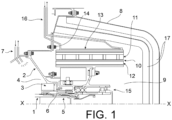
- the turbomachine comprises a central axis XX extending in a longitudinal direction, between a forward direction (on the left of the figures) and a rearward direction (on the right of the figures). Only the rear part of the turbomachine near the axis XX is shown, the rest of the turbomachine not being modified by the invention.
- the turbomachine comprises a low-pressure shaft 1 arranged in the axis XX and rotating about this axis. It comprises a stator 2 in which the low-pressure shaft 1 is supported by various bearings, including a rear bearing, which is the furthest rear of the bearings by means of which the low-pressure shaft 1 is supported by the stator 2.
- the visible part of the stator 2 is precisely an exhaust casing of the turbomachine.
- the bearings, among others the rear bearing, are contained in lubricated enclosures delimited by the stator 2.
- the low-pressure shaft 1 has an end 5 which emerges from the rear lubricated enclosure 4 containing the rear bearing, at the rear of a main seal 3 which delimits the rear lubricated enclosure 4, through a circular opening of the stator 2 provided with a labyrinth seal 6 which completes the main seal 3.
- the rear bearing is shown in figure 5 , at reference 73. It is immediately in front of the main seal 3.
- the rear lubricated enclosure 4 is closed at the front by another part 74 of the stator 2 and another assembly composed of a bearing 64 and a seal 77 connecting the low pressure shaft 1 to said other part 74.
- the turbomachine has an empty volume behind the stator 2 near the axis XX, in the rear cone of the turbine, and the end 5 opens out of the stator 2 at this location.
- the corresponding volume can be isolated from the outside by a conical cover 8 to form a rear cavity 9 which can receive various equipment, such as an electric machine 10 comprising a stator 11 and a rotor 12 surrounded by the stator 11.
- the stator 11 here consists of electrical windings and the rotor 12 of permanent magnets, but other arrangements of the electric machine would be possible.
- the stator 11 comprises a rigid stator frame 13, fixed to the stator 2 of the turbomachine by a first flange 14.
- the rotor 12 is carried by one of the main parts of the invention, called the journal 15, which will be described in detail and which is carried by the end 5 of the low-pressure shaft 1.
- a cooling circuit 16, also only sketched, passes through the stator 2 of the turbomachine and evacuates the heat produced around the stator 11 of the electric machine. And the rear cavity 9 is protected from the heat produced around it by the exhaust gases of the turbomachine, by insulating layers 17 in the inner lining of the conical cover 8.
- journal 15 It first comprises a shaft section 18, which extends the low-pressure shaft 1 by a short length at the rear of its end 5, and which is fixed to the end 5, coaxially with it, by a nut 19.
- the shaft section 18 is hollow, in the form of a sleeve hollowed out around the axis XX, but closed at the rear by a cap 20 screwed around its end.
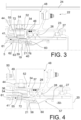
- the nut 19 is housed (refer also to Figures 3 and 4 for these description details) in the hollow of the shaft section 18, is screwed into a tapping 21 of the end 5, pushes a shoulder 60 of the shaft section 18 by making it abut against the rear face of the end 5, A sleeve 61 of the shaft section 18, which extends forward, rests on the outer face of the end 5 and ensures the coaxiality of the end 5 and the shaft section 18.
- An armature 22, carrying the rotor 12 of the electric machine 10, is arranged around the shaft section 20. It comprises an inner sleeve 23, an outer sleeve 24 and a pair of flanges 25, respectively integral with the sleeves, approximately flat and radially oriented, and bolted together.
- the armature 22 therefore forms a rigid structure.
- a rotation bearing, here consisting of a ball bearing 26 at the front and a roller bearing 27 at the rear, is arranged radially between the inner sleeve 23 and the shaft section 18 to secure them, while allowing them to rotate.
- a lubrication enclosure 28 is formed between the shaft section 18 and the inner sleeve 23. It includes the bearings 26 and 27; it is closed at the rear by a seal 29 placed between the inner sleeve 23 and the cylindrical wall of the plug 20; and it communicates with a reservoir 30 which is the hollow volume included by the shaft section 18 which extends, from rear to front, from the plug 20 to the end 5. Communication is via bores 31 and 32 leading directly to the bearings 26 and 27; a main bore 33, however, connects the reservoir 30 to another part 76 of the lubrication enclosure 28, located further forward and to which we will return.
- a coupling sleeve 34 which provides switching between two states of the device. It comprises a main part 35, flat and radially median, provided with rearwardly directed radial grooves 36, distributed over its circumference, and which, in the usual position, mesh with corresponding radial grooves 37, located at the front of the inner sleeve 23 and directed forwards.
- the coupling sleeve 34 further comprises a radially inner part 38 generally cylindrical, provided with axial grooves 39 on its face directed towards the inside, and which mesh with axial grooves 40 located on the cuff 61.
- the radially inner part 38 has a front bearing surface 41 which slides on the cuff 61; a seal 42, arranged at this location, limits the lubrication cavity 28 at the front.
- other axial grooves 62 and 63 will be noted, belonging respectively to the cuff 61 and to the end 5, meshing with each other and which keep the shaft section 18 and the low pressure shaft 1 integral in rotation.
- the coupling sleeve 34 finally comprises a radially external part 43, generally cylindrical, which comprises at the front a flare 44, close to the stator 2 of the turbomachine but separated from it, and at the rear a bearing surface 45 which slides on the external face of the front of the internal sleeve 23; seals 46, placed at this location, complete the isolation of the lubrication cavity 28 from the outside; the lubrication cavity 28 therefore also includes the radial grooves 36 and 37 and axial grooves 39 and 40, which the grease lubricates.
- An actuator 48 is arranged in the volume radially between the coupling sleeve 34, more precisely its radially outer portion 43, and the outer sleeve 24 of the armature 22, and it is axially between the turbomachine stator 2 at the front and the flanges 25 at the rear.
- the actuator 48 is provided with a support 49 retained on the turbomachine stator 2 by a second flange 50 concentric with the first flange 14 and surrounded by it. It comprises motors 51, such as electric cylinders, capable of moving forward rollers 52 rotating about radial axes 53 pushed by the motors 51.
- the supply of the motors 51 with electricity or fluid can be carried out by electric wires or cables passing along the stator 2 of the turbomachine.
- a helical spring 54 is compressed between the main part 35 of the coupling sleeve 34 at the rear, and a cuff 55, belonging to the low pressure shaft 1 and to which belongs one half of the labyrinth seal 6, at the front.
- the front bearing surface 41 comprises an annular external projection 72 or a seal (referenced to Figures 3 and 4 ) which restricts the gas leak section that the front bearing 41 makes with said cuff 55, to increase the sealing of the rear lubricated enclosure 4.
- the main state of the device is that of figures 2 And 3 : the radial splines 36 and 37 mesh with each other, the spring 54 pushes the coupling sleeve 34 rearward, and the armature 22, the low-pressure shaft 1, the shaft section 18 and the coupling sleeve 34 rotate in unison and drive the rotor 12 of the electric machine 10, which is therefore active.
- the motors 51 are requested to move the rollers 52 against the collar 44 and push it forward, which disengages the radial splines 36 and 37 and allows the armature 22 and the rotor 12 to rotate at a different speed from the low pressure shaft 1.
- the bearings 26 and 27 start moving and cause the grease to circulate through the bores 32 and 33.
- the bearing surfaces 41 and 45 keep the lubrication cavity 28 closed despite their sliding movements and the axial splines 39 and 40 continue to mesh with each other.
- the spring 54 reliably returns the coupling sleeve 34 to the usual position.
- Disassembly for maintenance or replacement of the system elements is easy to accomplish, once the conical cover 8 has been removed. It is carried out by successively removing each module of the device among the stator 11 of the electric machine 10, the journal 15, the actuator 48 and the coupling sleeve 34. The operator remains in the same position. Disassembly of the stator 11 of the electric machine 10 is first done by disassembling the first flange 14. The plug 20 is then unscrewed, the reservoir 30 emptied of its grease, and a tool introduced forward to turn the bolt 19, resting on radially internal reliefs 56, projecting inside the reservoir 30. The journal 15 is then dismantled from the end 5 of the low pressure shaft 1. The actuator 48 is then removed by dismantling the second flange 50. The coupling sleeve 43 can then also be dismantled, simply by pulling it. All movements are carried out in a straight line towards the rear.
- the reservoir 30 contains a brake 57 of the nut 19, composed of a flexible rod of which a rear end 58 is stopped against the inner wall of the shaft section 18 by the engagement of an elastic seal 65 in a groove, and of which the front end 59 comprises axial grooves 75 engaged in complementary grooves of the nut 19.
- the flexible rod is curved before turning the nut 19, in order to release it from the front end 59.
- FIG. 6 An alternative embodiment of this part of the device is shown in figure 6 .
- the brake 57 is absent, the reservoir 30 occupying the entire empty volume in the shaft section 18 is replaced by an annular reservoir 66 at the periphery of the empty volume 30.
- the nut 19 is replaced by a nut 67 and a locknut 68 locking each other.
- the nut 67 and the locknut 68 are provided with internal radial reliefs 69 that a tool 70, introduced as previously from the rear into the shaft section 18, can grip to cause tightening and loosening.
- the tool 70 passes through a volume free of grease because the reservoir 66 has larger radii, which makes it unnecessary to drain the oil in these circumstances.
- the plug 20 as well as the nut 67 and the locknut 68 do not need to have a continuous radial wall to close the empty volume 30.
- the annular reservoir 66 is here movable towards the rear if it must be extracted from the empty volume, and otherwise retained by a seal 78 housed in a groove of the shaft section 18.
- FIG. 5 illustrates that an electronic component housing 71 can be mounted on the stator armature 13 of the electric machine.
Landscapes
- Engineering & Computer Science (AREA)
- Chemical & Material Sciences (AREA)
- Combustion & Propulsion (AREA)
- Mechanical Engineering (AREA)
- General Engineering & Computer Science (AREA)
- Power Engineering (AREA)
- Motor Or Generator Frames (AREA)
- Motor Or Generator Cooling System (AREA)
Claims (13)
- Turbomaschine, umfassend eine Niederdruckwelle (1), die sich entlang einer Achse (X-X) der Turbomaschine erstreckt, die eine Vorderseite und eine Rückseite definiert; einen Stator (2) der Turbomaschine, der die Niederdruckwelle durch Lager, darunter ein hinteres Lager (73), trägt; eine elektrische Maschine (10), die sich an einem hinteren Abschnitt der Turbomaschine befindet und einen Rotor (12), der trennbar von der Niederdruckwelle (1) angetrieben wird, und einen Stator (11) umfasst, der am Stator (2) der Turbomaschine befestigt ist; umfassend einen Lagerzapfen (15) zum Tragen des Rotors (12) der elektrischen Maschine, wobei der Lagerzapfen ein Wellensegment (18) umfasst, das trennbar an einem hinteren Ende (5) der Niederdruckwelle befestigt ist, indem es die Niederdruckwelle verlängert, und einen Rahmen (22), an dem der Rotor der elektrischen Maschine befestigt ist und der das Wellensegment (18) umgibt, dadurch gekennzeichnet, dass der Stator (11) der elektrischen Maschine den Rotor (12) der elektrischen Maschine umgibt; und die Turbine außerdem mindestens ein Lager (26, 27), das zwischen dem Rahmen und dem Wellensegment montiert ist; und eine Hülse (34) umfasst, die axial um die Niederdruckwelle (1) und/oder das Wellensegment (18) herum beweglich ist, die in Drehung mit der Niederdruckwelle und dem Wellensegment verbunden ist und mit einer Kupplungseinrichtung (36) versehen ist, die zur Rückseite hin gerichtet und dazu ausgelegt ist, mit einer komplementären Kupplungseinrichtung (37) des Rahmens (22), die zur Vorderseite hin gerichtet ist, in Eingriff zu gelangen.
- Turbomaschine nach Anspruch 1, dadurch gekennzeichnet, dass das mindestens eine Lager (26, 27) mit Schmierfett geschmiert ist und in einer geschlossenen Schmierkammer (28) enthalten ist.
- Turbomaschine nach Anspruch 2, dadurch gekennzeichnet, dass das Wellensegment (18) hohl ist und einen Schmierfettbehälter (30) enthält, der über mindestens ein Loch (31, 32, 33) mit der Schmierkammer in Verbindung steht.
- Turbomaschine nach einem der Ansprüche 1 bis 3, dadurch gekennzeichnet, dass die Kupplungseinrichtungen (36, 37) Netzwerke aus radialen Riffelungen sind.
- Turbomaschine nach einem der Ansprüche 1 bis 4, dadurch gekennzeichnet, dass die Hülse über Netzwerke aus axialen Riffelungen (39, 40) mit dem Wellensegment (18) verbunden ist.
- Turbomaschine nach einem der Ansprüche 2, 4 und 5, dadurch gekennzeichnet, dass die Schmierkammer (28) auch die radialen und axialen Riffelungen enthält.
- Turbomaschine nach einem der Ansprüche 1 bis 6, dadurch gekennzeichnet, dass sie einen Aktuator (48) für die Hülse (34) umfasst, der axial zwischen dem Stator (2) der Turbomaschine und dem Rahmen (22) und radial zwischen dem Rahmen (22) und der Hülse (34) untergebracht ist.
- Turbomaschine nach Anspruch 7, dadurch gekennzeichnet, dass der Aktuator mindestens eine Rolle (52) umfasst, die axial beweglich ist und sich frei um eine radiale Achse (53) dreht und dazu ausgelegt ist, an einem ebenen Kragen (44) der Hülse anzuliegen und den Kragen zurückzudrängen.
- Turbomaschine nach einem der Ansprüche 1 bis 8, dadurch gekennzeichnet, dass sie eine Feder (54) umfasst, die um die Niederdruckwelle herum in Eingriff steht und zwischen der Niederdruckwelle (1) und der Hülse (34) zusammengedrückt wird.
- Turbomaschine nach einem der Ansprüche 1 bis 9, dadurch gekennzeichnet, dass das Wellensegment mit einer Mutter (19) am hinteren Ende (5) der Niederdruckwelle befestigt ist.
- Turbomaschine nach einem der Ansprüche 1 bis 10, dadurch gekennzeichnet, dass der Lagerzapfen (15) von der Niederdruckwelle und von der Hülse getrennt werden kann, indem er zur Rückseite hin geschoben wird, die Hülse (34) durch einen ersten Schraubflansch (49), der von hinten zugänglich ist, am Stator (2) der Turbomaschine befestigt ist, und der Stator (11) der elektrischen Maschine durch einen zweiten Schraubflansch (14), der von hinten zugänglich ist, am Stator (2) der Turbomaschine befestigt ist.
- Turbomaschine nach einem der vorhergehenden Ansprüche, dadurch gekennzeichnet, dass der Lagerzapfen (15), die Hülse (34) und der Stator (11) der elektrischen Maschine als unterschiedliche und einheitliche Module ausgebildet sind, die nacheinander von der Turbomaschine demontiert werden können.
- Turbomaschine nach den Ansprüchen 7 und 12, dadurch gekennzeichnet, dass der Aktuator (48) ein weiteres einheitliches Modul ist, das sich von den Modulen unterscheidet und separat von ihnen aus der Turbomaschine demontiert werden kann.
Applications Claiming Priority (2)
| Application Number | Priority Date | Filing Date | Title |
|---|---|---|---|
| FR2105516A FR3123375B1 (fr) | 2021-05-27 | 2021-05-27 | Turbomachine comprenant une machine électrique intégrée à l’arrière |
| PCT/FR2022/050970 WO2022248798A1 (fr) | 2021-05-27 | 2022-05-23 | Turbomachine comprenant une machine électrique intégrée à l'arrière |
Publications (2)
| Publication Number | Publication Date |
|---|---|
| EP4348012A1 EP4348012A1 (de) | 2024-04-10 |
| EP4348012B1 true EP4348012B1 (de) | 2024-11-27 |
Family
ID=76523178
Family Applications (1)
| Application Number | Title | Priority Date | Filing Date |
|---|---|---|---|
| EP22731746.8A Active EP4348012B1 (de) | 2021-05-27 | 2022-05-23 | Turbomaschine mit integrierter elektrischer maschine im hinteren bereich |
Country Status (5)
| Country | Link |
|---|---|
| US (1) | US12152538B2 (de) |
| EP (1) | EP4348012B1 (de) |
| CN (1) | CN117425765A (de) |
| FR (1) | FR3123375B1 (de) |
| WO (1) | WO2022248798A1 (de) |
Families Citing this family (10)
| Publication number | Priority date | Publication date | Assignee | Title |
|---|---|---|---|---|
| US12173650B2 (en) * | 2022-10-25 | 2024-12-24 | Ge Infrastructure Technology Llc | Combined cycle power plant having reduced parasitic pumping losses |
| US12188369B2 (en) | 2023-02-08 | 2025-01-07 | Hamilton Sundstrand Corporation | Aircraft tail cone mounted generators |
| FR3151635B1 (fr) * | 2023-07-26 | 2025-06-20 | Safran Aircraft Engines | Ensemble pour turbomachine d’aeronef, comportant un systeme de blocage axial d’un bouchon relativement a un arbre creux de la turbomachine |
| FR3154260A1 (fr) * | 2023-10-16 | 2025-04-18 | Safran Aircraft Engines | Support de palier agencé pour porter une machine électrique sans engendrer de modes de vibration supplémentaires |
| US12372010B1 (en) * | 2024-01-26 | 2025-07-29 | Rtx Corporation | Passive ventilation system for tail cone zone |
| FR3159634A1 (fr) | 2024-02-28 | 2025-08-29 | Safran Aircraft Engines | Ensemble comportant un arbre et une machine electrique pour une turbomachine d’aeronef, et procede de montage de cet ensemble |
| FR3161247A1 (fr) * | 2024-04-11 | 2025-10-17 | Safran Aircraft Engines | Turbomachine equipee d’une machine electrique dans son enceinte de lubrification |
| FR3161249A1 (fr) * | 2024-04-11 | 2025-10-17 | Safran Aircraft Engines | Turbomachine equipee d’une machine electrique deconnectable et d’un organe d’appui pour sa deconnexion |
| FR3161246A1 (fr) * | 2024-04-11 | 2025-10-17 | Safran Aircraft Engines | Turbomachine equipee d’une machine electrique agencee dans son enceinte dediee et d’un systeme de lubrification de l’enceinte dediee |
| CN119801672B (zh) * | 2024-11-11 | 2025-12-26 | 中国航发沈阳发动机研究所 | 一种双级低压涡轮盘轴连接结构 |
Citations (1)
| Publication number | Priority date | Publication date | Assignee | Title |
|---|---|---|---|---|
| FR3027625A1 (fr) * | 2014-10-27 | 2016-04-29 | Snecma | Turbomachine comprenant un generateur de courant electrique permettant l'injection d'huile depuis l'interieur d'un arbre de turbine |
Family Cites Families (12)
| Publication number | Priority date | Publication date | Assignee | Title |
|---|---|---|---|---|
| DE1928660A1 (de) * | 1969-06-06 | 1970-12-17 | Motoren Turbinen Union | Zweiwellengasturbinentriebwerk |
| US20060137355A1 (en) * | 2004-12-27 | 2006-06-29 | Pratt & Whitney Canada Corp. | Fan driven emergency generator |
| US8237298B2 (en) * | 2008-12-22 | 2012-08-07 | Hamilton Sundstrand Corporation | Generator coupling for use with gas turbine engine |
| US8935912B2 (en) * | 2011-12-09 | 2015-01-20 | United Technologies Corporation | Gas turbine engine with variable overall pressure ratio |
| EP3246526B1 (de) | 2016-05-18 | 2021-03-24 | Rolls-Royce Corporation | Steuerung eines niedrigdruckwellengenerators für einen gasturbinenmotor |
| US10487839B2 (en) * | 2016-08-22 | 2019-11-26 | General Electric Company | Embedded electric machine |
| US11371379B2 (en) * | 2017-08-22 | 2022-06-28 | General Electric Company | Turbomachine with alternatingly spaced turbine rotor blades |
| FR3073569B1 (fr) * | 2017-11-15 | 2020-02-07 | Safran Helicopter Engines | Turbopropulseur comportant un mecanisme de reduction integrant un dispositif de generation de courant |
| GB2572427B (en) * | 2018-03-29 | 2023-01-11 | Safran Electrical & Power | A generator having a disconnect mechanism |
| US11156128B2 (en) | 2018-08-22 | 2021-10-26 | General Electric Company | Embedded electric machine |
| US11242156B2 (en) | 2019-03-15 | 2022-02-08 | Hamilton Sundstrand Corporation | Plug in fluid cooled electrical connections for tail cone mounted generator |
| GB201910009D0 (en) | 2019-07-12 | 2019-08-28 | Rolls Royce Plc | Gas turbine engine electrical generator |
-
2021
- 2021-05-27 FR FR2105516A patent/FR3123375B1/fr active Active
-
2022
- 2022-05-23 CN CN202280034323.5A patent/CN117425765A/zh active Pending
- 2022-05-23 US US18/561,811 patent/US12152538B2/en active Active
- 2022-05-23 EP EP22731746.8A patent/EP4348012B1/de active Active
- 2022-05-23 WO PCT/FR2022/050970 patent/WO2022248798A1/fr not_active Ceased
Patent Citations (1)
| Publication number | Priority date | Publication date | Assignee | Title |
|---|---|---|---|---|
| FR3027625A1 (fr) * | 2014-10-27 | 2016-04-29 | Snecma | Turbomachine comprenant un generateur de courant electrique permettant l'injection d'huile depuis l'interieur d'un arbre de turbine |
Also Published As
| Publication number | Publication date |
|---|---|
| FR3123375B1 (fr) | 2023-05-12 |
| CN117425765A (zh) | 2024-01-19 |
| FR3123375A1 (fr) | 2022-12-02 |
| EP4348012A1 (de) | 2024-04-10 |
| US20240229723A1 (en) | 2024-07-11 |
| US12152538B2 (en) | 2024-11-26 |
| WO2022248798A1 (fr) | 2022-12-01 |
Similar Documents
| Publication | Publication Date | Title |
|---|---|---|
| EP4348012B1 (de) | Turbomaschine mit integrierter elektrischer maschine im hinteren bereich | |
| CA2442949C (fr) | Palier a roulement amorti a l`huile | |
| CA2606069C (fr) | Arbre d'entrainement de boitier a engrenages de machines auxiliaires d'un turboreacteur; machine auxiliaire supplementaire modulaire | |
| EP1375941B1 (de) | Abgedichtetes ölgedämpftes Wälzlager | |
| EP3137740B1 (de) | Anordnung für flugzeugtriebwerk und verfahren zur deren montage | |
| CA2874707C (fr) | Palier a moyen de lubrification et systeme pour changer le pas des pales d'une helice de turbopropulseur d'aeronef, equipe dudit palier | |
| CA2938385A1 (fr) | Turbomachine equipee d'un groupe de lubrification | |
| FR2911917A1 (fr) | Architecture distribuee de demarreur-generateur de turbine a gaz | |
| EP0494007A1 (de) | Einzeldurchfluss-Turbopumpe mit integrierter Überdruckpumpe | |
| FR3124541A1 (fr) | Turbomachine comprenant une machine électrique à une extrémité arrière de turbine | |
| EP3119995A1 (de) | Hilfsgetriebe für gasturbinenmotor | |
| EP4343133A1 (de) | Kompaktes zubehörgehäuse mit integrierter elektrischer maschine | |
| FR3095243A1 (fr) | Reducteur de vitesse d’une turbomachine | |
| WO2014013201A1 (fr) | Dispostif de transfert thermique entre une canalisation de lubrification et une canalisation hydraulique de commande de verin de calage de pales de turbomachine | |
| EP3735379A1 (de) | Turboprop mit eingebautem elektrizitätsgenerator | |
| EP3601747B1 (de) | Anbaugerätegetriebe für einen gasturbinenmotor | |
| EP2715104A2 (de) | Hydraulische getriebevorrichtung und kompakter hydraulischer anlasser | |
| FR3087512A1 (fr) | Dispositif amortisseur | |
| WO2025215317A1 (fr) | Turbomachine equipee d'une machine electrique dans son enceinte de lubrification | |
| WO2025215318A1 (fr) | Turbomachine equipee d'une machine electrique agencee dans son enceinte dediee et d'un systeme de lubrification de l'enceinte dediee | |
| WO2025215316A1 (fr) | Turbomachine equipee d'une machine electrique deconnectable et d'un organe d'appui pour sa deconnexion | |
| EP4127417A1 (de) | Anordnung für flugzeugturbinentriebwerk mit einem verbesserten system zur schmierung eines lüfterantriebsuntersetzungsgetriebes | |
| WO2024161082A1 (fr) | Assemblage pour ensemble propulsif d'aeronef avec accouplement debrayable de deux arbres par un manchon d'accouplement a actionnement par fluide pressurise | |
| FR3153635A1 (fr) | Dispositif pour le centrage et le guidage en rotation d’un arbre de turbomachine à lubrification optimisée d’éléments de roulement par du lubrifiant évacué depuis un palier à amortissement par compression de film d’huile | |
| EP4441341A1 (de) | Hilfsarm für ein turbomaschinenabgasgehäuse |
Legal Events
| Date | Code | Title | Description |
|---|---|---|---|
| STAA | Information on the status of an ep patent application or granted ep patent |
Free format text: STATUS: UNKNOWN |
|
| STAA | Information on the status of an ep patent application or granted ep patent |
Free format text: STATUS: THE INTERNATIONAL PUBLICATION HAS BEEN MADE |
|
| PUAI | Public reference made under article 153(3) epc to a published international application that has entered the european phase |
Free format text: ORIGINAL CODE: 0009012 |
|
| STAA | Information on the status of an ep patent application or granted ep patent |
Free format text: STATUS: REQUEST FOR EXAMINATION WAS MADE |
|
| 17P | Request for examination filed |
Effective date: 20231106 |
|
| AK | Designated contracting states |
Kind code of ref document: A1 Designated state(s): AL AT BE BG CH CY CZ DE DK EE ES FI FR GB GR HR HU IE IS IT LI LT LU LV MC MK MT NL NO PL PT RO RS SE SI SK SM TR |
|
| DAV | Request for validation of the european patent (deleted) | ||
| DAX | Request for extension of the european patent (deleted) | ||
| GRAP | Despatch of communication of intention to grant a patent |
Free format text: ORIGINAL CODE: EPIDOSNIGR1 |
|
| STAA | Information on the status of an ep patent application or granted ep patent |
Free format text: STATUS: GRANT OF PATENT IS INTENDED |
|
| GRAS | Grant fee paid |
Free format text: ORIGINAL CODE: EPIDOSNIGR3 |
|
| GRAA | (expected) grant |
Free format text: ORIGINAL CODE: 0009210 |
|
| STAA | Information on the status of an ep patent application or granted ep patent |
Free format text: STATUS: THE PATENT HAS BEEN GRANTED |
|
| INTG | Intention to grant announced |
Effective date: 20240926 |
|
| AK | Designated contracting states |
Kind code of ref document: B1 Designated state(s): AL AT BE BG CH CY CZ DE DK EE ES FI FR GB GR HR HU IE IS IT LI LT LU LV MC MK MT NL NO PL PT RO RS SE SI SK SM TR |
|
| REG | Reference to a national code |
Ref country code: GB Ref legal event code: FG4D Free format text: NOT ENGLISH |
|
| REG | Reference to a national code |
Ref country code: CH Ref legal event code: EP |
|
| REG | Reference to a national code |
Ref country code: IE Ref legal event code: FG4D Free format text: LANGUAGE OF EP DOCUMENT: FRENCH |
|
| REG | Reference to a national code |
Ref country code: DE Ref legal event code: R096 Ref document number: 602022008231 Country of ref document: DE |
|
| REG | Reference to a national code |
Ref country code: LT Ref legal event code: MG9D |
|
| REG | Reference to a national code |
Ref country code: NL Ref legal event code: MP Effective date: 20241127 |
|
| PG25 | Lapsed in a contracting state [announced via postgrant information from national office to epo] |
Ref country code: IS Free format text: LAPSE BECAUSE OF FAILURE TO SUBMIT A TRANSLATION OF THE DESCRIPTION OR TO PAY THE FEE WITHIN THE PRESCRIBED TIME-LIMIT Effective date: 20250327 Ref country code: HR Free format text: LAPSE BECAUSE OF FAILURE TO SUBMIT A TRANSLATION OF THE DESCRIPTION OR TO PAY THE FEE WITHIN THE PRESCRIBED TIME-LIMIT Effective date: 20241127 Ref country code: PT Free format text: LAPSE BECAUSE OF FAILURE TO SUBMIT A TRANSLATION OF THE DESCRIPTION OR TO PAY THE FEE WITHIN THE PRESCRIBED TIME-LIMIT Effective date: 20250327 |
|
| PG25 | Lapsed in a contracting state [announced via postgrant information from national office to epo] |
Ref country code: FI Free format text: LAPSE BECAUSE OF FAILURE TO SUBMIT A TRANSLATION OF THE DESCRIPTION OR TO PAY THE FEE WITHIN THE PRESCRIBED TIME-LIMIT Effective date: 20241127 Ref country code: NL Free format text: LAPSE BECAUSE OF FAILURE TO SUBMIT A TRANSLATION OF THE DESCRIPTION OR TO PAY THE FEE WITHIN THE PRESCRIBED TIME-LIMIT Effective date: 20241127 |
|
| REG | Reference to a national code |
Ref country code: AT Ref legal event code: MK05 Ref document number: 1745889 Country of ref document: AT Kind code of ref document: T Effective date: 20241127 |
|
| PG25 | Lapsed in a contracting state [announced via postgrant information from national office to epo] |
Ref country code: BG Free format text: LAPSE BECAUSE OF FAILURE TO SUBMIT A TRANSLATION OF THE DESCRIPTION OR TO PAY THE FEE WITHIN THE PRESCRIBED TIME-LIMIT Effective date: 20241127 |
|
| PG25 | Lapsed in a contracting state [announced via postgrant information from national office to epo] |
Ref country code: ES Free format text: LAPSE BECAUSE OF FAILURE TO SUBMIT A TRANSLATION OF THE DESCRIPTION OR TO PAY THE FEE WITHIN THE PRESCRIBED TIME-LIMIT Effective date: 20241127 |
|
| PG25 | Lapsed in a contracting state [announced via postgrant information from national office to epo] |
Ref country code: NO Free format text: LAPSE BECAUSE OF FAILURE TO SUBMIT A TRANSLATION OF THE DESCRIPTION OR TO PAY THE FEE WITHIN THE PRESCRIBED TIME-LIMIT Effective date: 20250227 |
|
| PG25 | Lapsed in a contracting state [announced via postgrant information from national office to epo] |
Ref country code: GR Free format text: LAPSE BECAUSE OF FAILURE TO SUBMIT A TRANSLATION OF THE DESCRIPTION OR TO PAY THE FEE WITHIN THE PRESCRIBED TIME-LIMIT Effective date: 20250228 Ref country code: AT Free format text: LAPSE BECAUSE OF FAILURE TO SUBMIT A TRANSLATION OF THE DESCRIPTION OR TO PAY THE FEE WITHIN THE PRESCRIBED TIME-LIMIT Effective date: 20241127 Ref country code: LV Free format text: LAPSE BECAUSE OF FAILURE TO SUBMIT A TRANSLATION OF THE DESCRIPTION OR TO PAY THE FEE WITHIN THE PRESCRIBED TIME-LIMIT Effective date: 20241127 |
|
| PG25 | Lapsed in a contracting state [announced via postgrant information from national office to epo] |
Ref country code: PL Free format text: LAPSE BECAUSE OF FAILURE TO SUBMIT A TRANSLATION OF THE DESCRIPTION OR TO PAY THE FEE WITHIN THE PRESCRIBED TIME-LIMIT Effective date: 20241127 |
|
| PG25 | Lapsed in a contracting state [announced via postgrant information from national office to epo] |
Ref country code: RS Free format text: LAPSE BECAUSE OF FAILURE TO SUBMIT A TRANSLATION OF THE DESCRIPTION OR TO PAY THE FEE WITHIN THE PRESCRIBED TIME-LIMIT Effective date: 20250227 |
|
| PG25 | Lapsed in a contracting state [announced via postgrant information from national office to epo] |
Ref country code: SM Free format text: LAPSE BECAUSE OF FAILURE TO SUBMIT A TRANSLATION OF THE DESCRIPTION OR TO PAY THE FEE WITHIN THE PRESCRIBED TIME-LIMIT Effective date: 20241127 |
|
| PGFP | Annual fee paid to national office [announced via postgrant information from national office to epo] |
Ref country code: DE Payment date: 20250519 Year of fee payment: 4 |
|
| PG25 | Lapsed in a contracting state [announced via postgrant information from national office to epo] |
Ref country code: DK Free format text: LAPSE BECAUSE OF FAILURE TO SUBMIT A TRANSLATION OF THE DESCRIPTION OR TO PAY THE FEE WITHIN THE PRESCRIBED TIME-LIMIT Effective date: 20241127 |
|
| PG25 | Lapsed in a contracting state [announced via postgrant information from national office to epo] |
Ref country code: EE Free format text: LAPSE BECAUSE OF FAILURE TO SUBMIT A TRANSLATION OF THE DESCRIPTION OR TO PAY THE FEE WITHIN THE PRESCRIBED TIME-LIMIT Effective date: 20241127 |
|
| PGFP | Annual fee paid to national office [announced via postgrant information from national office to epo] |
Ref country code: FR Payment date: 20250526 Year of fee payment: 4 |
|
| PG25 | Lapsed in a contracting state [announced via postgrant information from national office to epo] |
Ref country code: RO Free format text: LAPSE BECAUSE OF FAILURE TO SUBMIT A TRANSLATION OF THE DESCRIPTION OR TO PAY THE FEE WITHIN THE PRESCRIBED TIME-LIMIT Effective date: 20241127 |
|
| PG25 | Lapsed in a contracting state [announced via postgrant information from national office to epo] |
Ref country code: SK Free format text: LAPSE BECAUSE OF FAILURE TO SUBMIT A TRANSLATION OF THE DESCRIPTION OR TO PAY THE FEE WITHIN THE PRESCRIBED TIME-LIMIT Effective date: 20241127 |
|
| PG25 | Lapsed in a contracting state [announced via postgrant information from national office to epo] |
Ref country code: CZ Free format text: LAPSE BECAUSE OF FAILURE TO SUBMIT A TRANSLATION OF THE DESCRIPTION OR TO PAY THE FEE WITHIN THE PRESCRIBED TIME-LIMIT Effective date: 20241127 |
|
| PG25 | Lapsed in a contracting state [announced via postgrant information from national office to epo] |
Ref country code: IT Free format text: LAPSE BECAUSE OF FAILURE TO SUBMIT A TRANSLATION OF THE DESCRIPTION OR TO PAY THE FEE WITHIN THE PRESCRIBED TIME-LIMIT Effective date: 20241127 |
|
| REG | Reference to a national code |
Ref country code: DE Ref legal event code: R097 Ref document number: 602022008231 Country of ref document: DE |
|
| PG25 | Lapsed in a contracting state [announced via postgrant information from national office to epo] |
Ref country code: SE Free format text: LAPSE BECAUSE OF FAILURE TO SUBMIT A TRANSLATION OF THE DESCRIPTION OR TO PAY THE FEE WITHIN THE PRESCRIBED TIME-LIMIT Effective date: 20241127 |
|
| PLBE | No opposition filed within time limit |
Free format text: ORIGINAL CODE: 0009261 |
|
| STAA | Information on the status of an ep patent application or granted ep patent |
Free format text: STATUS: NO OPPOSITION FILED WITHIN TIME LIMIT |
|
| REG | Reference to a national code |
Ref country code: CH Ref legal event code: L10 Free format text: ST27 STATUS EVENT CODE: U-0-0-L10-L00 (AS PROVIDED BY THE NATIONAL OFFICE) Effective date: 20251008 |
|
| 26N | No opposition filed |
Effective date: 20250828 |
|
| REG | Reference to a national code |
Ref country code: CH Ref legal event code: H13 Free format text: ST27 STATUS EVENT CODE: U-0-0-H10-H13 (AS PROVIDED BY THE NATIONAL OFFICE) Effective date: 20251223 |
|
| PG25 | Lapsed in a contracting state [announced via postgrant information from national office to epo] |
Ref country code: LU Free format text: LAPSE BECAUSE OF NON-PAYMENT OF DUE FEES Effective date: 20250523 |
|
| PG25 | Lapsed in a contracting state [announced via postgrant information from national office to epo] |
Ref country code: CH Free format text: LAPSE BECAUSE OF NON-PAYMENT OF DUE FEES Effective date: 20250531 |
|
| REG | Reference to a national code |
Ref country code: BE Ref legal event code: MM Effective date: 20250531 |
|
| PG25 | Lapsed in a contracting state [announced via postgrant information from national office to epo] |
Ref country code: MC Free format text: LAPSE BECAUSE OF FAILURE TO SUBMIT A TRANSLATION OF THE DESCRIPTION OR TO PAY THE FEE WITHIN THE PRESCRIBED TIME-LIMIT Effective date: 20241127 |