EP4347276B1 - Fahrzeugluftreifen - Google Patents
Fahrzeugluftreifen Download PDFInfo
- Publication number
- EP4347276B1 EP4347276B1 EP21820111.9A EP21820111A EP4347276B1 EP 4347276 B1 EP4347276 B1 EP 4347276B1 EP 21820111 A EP21820111 A EP 21820111A EP 4347276 B1 EP4347276 B1 EP 4347276B1
- Authority
- EP
- European Patent Office
- Prior art keywords
- channel
- projections
- pneumatic vehicle
- tread
- vehicle tyre
- Prior art date
- Legal status (The legal status is an assumption and is not a legal conclusion. Google has not performed a legal analysis and makes no representation as to the accuracy of the status listed.)
- Active
Links
Images


Classifications
-
- B—PERFORMING OPERATIONS; TRANSPORTING
- B60—VEHICLES IN GENERAL
- B60C—VEHICLE TYRES; TYRE INFLATION; TYRE CHANGING; CONNECTING VALVES TO INFLATABLE ELASTIC BODIES IN GENERAL; DEVICES OR ARRANGEMENTS RELATED TO TYRES
- B60C11/00—Tyre tread bands; Tread patterns; Anti-skid inserts
- B60C11/03—Tread patterns
- B60C11/0302—Tread patterns directional pattern, i.e. with main rolling direction
-
- B—PERFORMING OPERATIONS; TRANSPORTING
- B60—VEHICLES IN GENERAL
- B60C—VEHICLE TYRES; TYRE INFLATION; TYRE CHANGING; CONNECTING VALVES TO INFLATABLE ELASTIC BODIES IN GENERAL; DEVICES OR ARRANGEMENTS RELATED TO TYRES
- B60C11/00—Tyre tread bands; Tread patterns; Anti-skid inserts
- B60C11/03—Tread patterns
- B60C11/0306—Patterns comprising block rows or discontinuous ribs
- B60C11/0309—Patterns comprising block rows or discontinuous ribs further characterised by the groove cross-section
-
- B—PERFORMING OPERATIONS; TRANSPORTING
- B60—VEHICLES IN GENERAL
- B60C—VEHICLE TYRES; TYRE INFLATION; TYRE CHANGING; CONNECTING VALVES TO INFLATABLE ELASTIC BODIES IN GENERAL; DEVICES OR ARRANGEMENTS RELATED TO TYRES
- B60C11/00—Tyre tread bands; Tread patterns; Anti-skid inserts
- B60C11/03—Tread patterns
- B60C11/13—Tread patterns characterised by the groove cross-section, e.g. for buttressing or preventing stone-trapping
- B60C11/1307—Tread patterns characterised by the groove cross-section, e.g. for buttressing or preventing stone-trapping with special features of the groove walls
-
- B—PERFORMING OPERATIONS; TRANSPORTING
- B60—VEHICLES IN GENERAL
- B60C—VEHICLE TYRES; TYRE INFLATION; TYRE CHANGING; CONNECTING VALVES TO INFLATABLE ELASTIC BODIES IN GENERAL; DEVICES OR ARRANGEMENTS RELATED TO TYRES
- B60C11/00—Tyre tread bands; Tread patterns; Anti-skid inserts
- B60C11/03—Tread patterns
- B60C2011/0337—Tread patterns characterised by particular design features of the pattern
-
- B—PERFORMING OPERATIONS; TRANSPORTING
- B60—VEHICLES IN GENERAL
- B60C—VEHICLE TYRES; TYRE INFLATION; TYRE CHANGING; CONNECTING VALVES TO INFLATABLE ELASTIC BODIES IN GENERAL; DEVICES OR ARRANGEMENTS RELATED TO TYRES
- B60C11/00—Tyre tread bands; Tread patterns; Anti-skid inserts
- B60C11/03—Tread patterns
- B60C2011/0337—Tread patterns characterised by particular design features of the pattern
- B60C2011/0339—Grooves
- B60C2011/0358—Lateral grooves, i.e. having an angle of 45 to 90 degees to the equatorial plane
-
- B—PERFORMING OPERATIONS; TRANSPORTING
- B60—VEHICLES IN GENERAL
- B60C—VEHICLE TYRES; TYRE INFLATION; TYRE CHANGING; CONNECTING VALVES TO INFLATABLE ELASTIC BODIES IN GENERAL; DEVICES OR ARRANGEMENTS RELATED TO TYRES
- B60C11/00—Tyre tread bands; Tread patterns; Anti-skid inserts
- B60C11/03—Tread patterns
- B60C11/13—Tread patterns characterised by the groove cross-section, e.g. for buttressing or preventing stone-trapping
- B60C11/1307—Tread patterns characterised by the groove cross-section, e.g. for buttressing or preventing stone-trapping with special features of the groove walls
- B60C2011/1338—Tread patterns characterised by the groove cross-section, e.g. for buttressing or preventing stone-trapping with special features of the groove walls comprising protrusions
Definitions
- the invention relates to a pneumatic vehicle tire with a directional tread with oblique grooves which run in a V-shape relative to one another across the tread width and which open into one another, wherein in each tread half, between oblique grooves adjacent in the circumferential direction, at least two grooves which are inclined in the direction of plan view to the oblique grooves and each have two groove flanks and a groove base run.
- the oblique grooves and the grooves delimit shoulder-side tread blocks belonging to two shoulder-side tread block rows and middle tread blocks located in a central tread region.
- Grooves which are inclined in the direction of opposite to the oblique grooves are provided, each of which has a number of projections on its groove flank. When viewed over the extent of the associated groove, a projection located on one groove flank alternately follows a projection located on the other groove flank, and a groove base path running along the projections remains at the groove base.
- Such a pneumatic vehicle tire is known, for example, from DE 10 2017 211 130 A1 known.
- the tire has a directional tread with diagonal grooves extending in a V-shape across the tread width, merging into one another, and grooves extending between these grooves.
- Grooves are provided, on the groove flanks of which at least one wedge-shaped projection is formed, wherein the projections overlap one another, viewed in the direction of extension of the groove.
- Between the projections extending from opposite groove flanks and between each projection and the opposite groove flank runs a groove base path with a width of 0.5 mm to 1.5 mm.
- the tread blocks are supported on the projections under load, thereby stabilizing them and thus improving traction and braking properties on snow.
- the projections cause snow to accumulate in the grooves, so that good snow grip properties are ensured through the effect of snow-on-snow friction.
- the tire is therefore well balanced in terms of its driving characteristics under winter driving conditions.
- the invention is based on the object of reducing the risk of aquaplaning in a pneumatic vehicle tire of the type mentioned above, while maintaining the advantageous traction, braking and grip properties on snow.
- the projections each have the shape of a pyramid with exactly two triangular boundary surfaces and a radially outer tip located on the groove flank, wherein at least three adjacent projections are formed on each groove flank, which give the groove base path a zigzag-shaped course in plan view.
- the "transverse portion" of the groove base path running between them is significantly reduced compared to the conventional wedge-shaped protrusions. This allows water to flow through the groove with minimal or almost no turbulence when driving on wet roads, significantly reducing the risk of aquaplaning.
- the pyramid-shaped protrusions continue to optimally support the tread blocks under load, thus maintaining particularly advantageous traction, braking, and grip properties on snow.
- each projection has a radially oriented plane of symmetry extending perpendicular to the groove centerline in plan view, in which plane the two triangular boundary surfaces have a common boundary edge inclined to the radial direction, which, viewed in plan view, ends either on or in front of the groove centerline. Therefore, in this embodiment, the triangular boundary surfaces of a projection do not extend beyond the groove centerline, further improving water drainage along the groove base path and through the groove to the nearest inclined groove.
- the common boundary edge of the two triangular boundary surfaces ends in front of the groove center line at a distance of at least 0.1 mm determined perpendicular to the groove center line.
- the common boundary edge of the two triangular boundary surfaces extends at an angle of 15° to 35°, in particular 20° to 30°, to the radial direction. This configuration is particularly advantageous for the aforementioned supporting effect of the projections.
- a further preferred embodiment is characterized in that the triangular boundary surfaces each have a radially inner boundary edge extending at a constant depth determined in the radial direction, which extends at an angle of 25° to 50°, in particular 30° to 45°, relative to the groove centerline.
- This configuration is also particularly advantageous for the mutual support of the projections and for good water drainage through the groove base path.
- the groove base path has a width, determined vertically between the radially inner boundary edges, of 30% to 50%, in particular of 35% to 45%, of the width of the groove determined at the tread periphery.
- the triangular boundary surfaces each have a boundary edge extending along the groove flank, which is inclined to the radial direction at an angle of 15° to 35°, in particular 20° to 30°. Such boundary surfaces also improve the supporting effect of the projections.
- the radially outer tip of each projection is located at a height of 20% to 60%, in particular 30% to 50%, preferably 35% to 45%, of the maximum depth of the groove, as determined in the radial direction, relative to the deepest point of the groove. This primarily contributes to improving water drainage in the grooves.
- a further preferred embodiment is characterized in that the grooves, which have adjacent projections on their flanks, have at least four adjacent projections on each flank.
- the grooves which have the projections adjacent to one another on their groove flanks have at least four, in particular exactly four, projections on one groove flank and at least five, in particular exactly five, projections on the other groove flank.
- each tread half three grooves inclined to the oblique grooves extend between circumferentially adjacent oblique grooves, wherein the projections are formed at least, in particular exclusively, in the two grooves extending further outward of the tread.
- the supporting effect of the projections is particularly advantageous, especially when cornering, with regard to traction, braking, and grip on snow.
- the grooves extending furthest toward the inside of the tread are free of projections, which is particularly beneficial for water drainage.
- the grooves have a depth of 75% to 100%, in particular 80% to 90%, of the profile depth in the radial direction and a width of 2.0 mm to 6.0 mm, in particular 3.0 mm to 5.0 mm.
- the grooves viewed in plan view and relative to their groove center lines, run at an angle of 15° to 55°, in particular 25° to 45°, to the circumferential direction.
- Pneumatic vehicle tires designed according to the invention are tires for multi-track motor vehicles and preferably tires of radial design for passenger cars, vans or light trucks (light trucks with a GVW ⁇ 7.5 t).
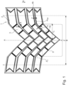
- Fig. 1 shows a plan view of a partial development of a tread belonging to a pneumatic vehicle tire with a directional tread pattern.
- the pneumatic vehicle tire must be mounted on the vehicle in such a way that it has the rolling direction indicated by arrow R when driving forward.
- the lateral edges of the ground contact patch (corresponding to the statically determined footprint at a load of 70% of the maximum load capacity at an internal pressure of 85%, determined according to ETRTO standards) are indicated by lines 1, with the ground contact patch having a width B in the axial direction.
- the tire equatorial plane is marked by line AA.
- the tread has two shoulder-side profile block rows 1 with shoulder-side profile blocks 2 and a central tread area Z with middle profile blocks 3, wherein the shoulder-side profile blocks 2 and the middle profile blocks 3 are separated from each other by oblique grooves 4 and slots 5.
- the shoulder-side profile blocks 2 and the middle profile blocks 3 are preferably provided with cuts and/or microgrooves, which in Fig. 1 are not shown and can be implemented in a known manner.
- the oblique grooves 4 run in a V-shape across the tread width, merge into one another in the area of the tire equatorial plane (line AA), extend beyond the lateral edges (lines 1) of the ground contact patch, form the main grooves of the tread and are radially tapered to the respective intended tread depth T P ( Fig. 2 ) of usually 6.5 mm to 13.0 mm, wherein the oblique grooves 4, which each extend beyond the same lateral edge (line 1) of the ground contact patch, run parallel to one another when viewed from above.
- the oblique grooves 4 extending beyond one lateral edge (line 1) of the ground contact patch are offset in a barely perceptible manner in the circumferential direction from the oblique grooves 4 extending beyond the other lateral edge (line 1) of the ground contact patch.
- the rolling direction of the tire when driving forward (arrow R) is such that the oblique grooves 4 first enter the ground with their ends on the inside of the tread when driving forward.
- Each oblique groove 4 is composed of a slightly curved groove section 4a on the inside of the tread and a shoulder-side groove section 4b that is more inclined to the circumferential direction, and has a groove center line m SR .
- the groove section 4a on the inside of the tread has - relative to the groove center line m SR - a length la projected in the axial direction of 25% to 35% of the width B of the ground contact area and - likewise relative to the groove center line m SR - runs at an angle ⁇ of 30° to 55° to the axial direction, wherein the angle ⁇ is determined with respect to a tangent locally applied to the groove center line m SR .
- the shoulder-side groove section 4b runs - relative to the groove center line m SR - at an angle ⁇ of 0° to 15°, in particular of up to 10°, to the axial direction.
- each tread half three of the already mentioned grooves 5 are formed between circumferentially adjacent oblique grooves 4, which - based on their groove center lines m N ( Fig. 3 ) - in plan view straight, parallel to each other and to the circumferential direction at an angle ⁇ ( Fig. 3 ) of 15° to 55°, in particular of 25° to 45°, and are inclined in the circumferential direction opposite to the oblique grooves 4.
- the grooves 4 in the one direction, in Fig. 1 The grooves 5 formed furthest towards the inside of the tread in the right tread half are, in plan view, an extension of the groove sections 4a of the oblique grooves 4 formed in the other tread half.
- the shoulder-side tread blocks 2 are thus delimited by the shoulder-side groove sections 4b, the grooves 5 extending furthest toward the outside of the tread, and by the end sections of the inner tread groove sections 4a adjacent to the shoulder-side groove sections 4b.
- the middle tread blocks 3 are delimited by the inner tread groove sections 4a and the grooves 5 and, in plan view, have a substantially parallelogram shape, being arranged circumferentially on the "tips" of the parallelograms.
- the groove 5 has a maximum depth t N of 75% to 100%, in particular 80% to 90%, of the profile depth T P in the radial direction and a width b N determined at the tread periphery perpendicular to the groove centre line m N (cf. Fig. 3 ) from 2.0 mm to 6.0 mm, especially from 3.0 mm to 5.0 mm.
- the groove 5 is formed by a groove flank 5a on the outside of the tread, a groove flank 5b on the inside of the tread and a groove base 5c ( Fig.
- Fig. 3 and Fig. 4 in combination with Fig. 1 show, in each tread half in the two grooves 5 ( Fig. 1 ) at the groove base 5c ( Fig. 4 ) pyramid-shaped projections 6 ( Fig. 3, Fig. 4 ) is formed, to which projections 6 ( Fig. 3, Fig. 4 ) and adjacent pyramid-shaped projections 6 ( Fig. 3 ) belong.
- Fig. 3 When viewed over the extension of a groove 5 having the projections 6, a projection 6 located on the outside of the tread groove flank 5a alternates with a projection 6 located on the inside of the tread groove flank 5b, with the groove base 5c ( Fig. 4 , Fig. 5 ) a groove base path 5d, which runs zigzag-shaped in plan view, remains between the projections 6 formed on the opposing groove flanks 5a, 5b. Furthermore, the projections 6 located at the groove ends directly border an oblique groove 4.
- each projection 6 has a symmetry plane E 1 running perpendicular to the groove center line m N and oriented in the radial direction, a radially outer tip S located in this plane and lying on the respective groove flank 5a, 5b, and two triangular boundary surfaces 6a.
- the radially outer tip S is located at a height h V of 20% to 60%, in particular of 30% to 50%, preferably of 35% to 45%, of the maximum depth t N of the groove 5 , determined in the symmetry plane E 1 relative to the deepest point of the groove 5 in the radial direction.
- the boundary surfaces 6a each have a radially inner boundary edge 7, a boundary edge 8 facing the corresponding groove flank 5a, 5b and a common boundary edge 9 running in the plane of symmetry E 1.
- the radially inner boundary edge 7 runs at a constant depth determined in the radial direction and, viewed in plan view, at an angle ⁇ ( Fig. 6 ) of 25° to 50°, in particular of 30° to 45°.
- the boundary edge 8 running along the respective groove flank 5a, 5b is arranged at an angle ⁇ ( Fig. 4 ) of 15° to 35°, in particular of 20° to 30°.
- the common boundary edge 9 extends to the radial direction at an angle ⁇ ( Fig.
- the groove base path 5d further has a width b P ( Fig. 6 ), which will be discussed below.
- the mentioned angle ⁇ of the common boundary edge 9 ( Fig. 5 ), the height h V of the projection 6 ( Fig. 5 ) and the mentioned width b N of the groove 5 ( Fig. 6 ) are preferably matched to one another in such a way that the width b P ( Fig. 6 ) of the groove base path 5d 30% to 50%, in particular 35% to 45%, of the mentioned width b N ( Fig. 6 ) of the groove 5.
- the invention is not limited to the described embodiment.
- at least two grooves 5 extend in each tread half, with at least three projections 6 formed on each groove flank 5a, 5b of the grooves 5.
- the projections 6 can be formed in all grooves 5 or only in some grooves 5.
- the transition curves 10 are optional.
- the oblique grooves 4 can, for example, also run continuously curved in plan view.
Landscapes
- Engineering & Computer Science (AREA)
- Mechanical Engineering (AREA)
- Tires In General (AREA)
Description
- Die Erfindung betrifft einen Fahrzeugluftreifen mit einem laufrichtungsgebundenen Laufstreifen mit über die Laufstreifenbreite V-förmig zueinander verlaufenden, ineinander einmündenden Schrägrillen, wobei in jeder Laufstreifenhälfte zwischen in Umfangsrichtung benachbarten Schrägrillen zumindest zwei zu den Schrägrillen in Draufsicht gegensinnig geneigte Nuten mit jeweils zwei Nutflanken und einem Nutgrund verlaufen, wobei die Schrägrillen und die Nuten zu zwei schulterseitigen Profilblockreihen gehörende schulterseitige Profilblöcke und in einem zentralen Laufstreifenbereich befindliche mittlere Profilblöcke begrenzen, wobei zu den Schrägrillen gegensinnig geneigte Nuten vorgesehen sind, welche an ihren Nutflanken jeweils eine Anzahl von Vorsprüngen aufweisen, wobei - über die Erstreckung der zugehörigen Nut betrachtet - ein an der einen Nutflanke befindlicher Vorsprung abwechselnd auf einen an der anderen Nutflanke befindlichen Vorsprung folgt und wobei am Nutgrund ein die Vorsprünge entlang verlaufender Nutgrundpfad verbleibt.
- Ein derartiger Fahrzeugluftreifen ist beispielsweise aus der
DE 10 2017 211 130 A1 bekannt. Der Reifen weist einen laufrichtungsgebundenen Laufstreifen mit über die Laufstreifenbreite V-förmig zueinander verlaufenden, ineinander einmündenden Schrägrillen und zwischen diesen verlaufende Nuten auf. Es sind dabei Nuten vorgesehen, an deren Nutflanken zumindest jeweils ein keilförmiger Vorsprung ausgebildet ist, wobei die Vorsprünge, in Erstreckungsrichtung der Nut betrachtet, einander überlappen. Zwischen den von gegenüberliegenden Nutflanken ausgehenden Vorsprüngen und zwischen jedem Vorsprung und der gegenüberliegenden Nutflanke verläuft ein Nutgrundpfad mit einer Breite von 0,5 mm bis 1,5 mm. Die Profilblöcke stützen sich unter Belastung an den Vorsprüngen ab, wodurch sie stabilisiert und derart die Traktions- und Bremseigenschaften auf Schnee verbessert sind. Die Vorsprünge bewirken beim Fahren auf schneebedeckter Fahrbahn ein Ansammeln von Schnee in den Nuten, sodass durch den Effekt der Schnee-Schnee-Reibung gute Schneegriffeigenschaften gewährleistet sind. Der Reifen ist somit hinsichtlich seiner Fahreigenschaften unter winterlichen Fahrbedingungen gut ausbalanciert. - Der Erfindung liegt die Aufgabe zugrunde, bei einem Fahrzeugluftreifen der eingangs genannten Art die Gefahr des Auftretens von Aquaplaning zu reduzieren, wobei die vorteilhaften Traktions-, Brems- und Griffeigenschaften auf Schnee erhalten bleiben sollen.
- Gelöst wird die gestellte Aufgabe erfindungsgemäß dadurch, dass die Vorsprünge jeweils die Form einer Pyramide mit genau zwei dreieckigen Begrenzungsflächen und einer an der Nutflanke liegenden, radial äußeren Spitze aufweisen, wobei an jeder Nutflanke zumindest drei aneinander angrenzende Vorsprünge ausgebildet sind, welche dem Nutgrundpfad einen in Draufsicht zick-zack-förmigen Verlauf verleihen.
- Durch die spezielle Gestalt der Vorsprünge in Form von Pyramiden ist der "Queranteil" des zwischen diesen verlaufenden Nutgrundpfades gegenüber den bekannten keilförmigen Vorsprüngen deutlich reduziert, wodurch beim Fahren auf nasser Fahrbahn der Wasserfluss durch die Nut noch verwirbelungsarm bzw. nahezu verwirbelungsfrei verläuft und die Gefahr des Auftretens von Aquaplaning deutlich reduziert wird. Die pyramidenförmigen Vorsprünge stützen die Profilblöcke weiterhin unter Belastung optimal ab, sodass besonders vorteilhafte Traktions-, Brems- und Griffeigenschaften auf Schnee erhalten bleiben.
- Gemäß einer ersten bevorzugten Ausführung weist jeder Vorsprung eine in Draufsicht senkrecht zur Nutmittellinie der Nut verlaufende, in radialer Richtung ausgerichtete Symmetrieebene auf, in welcher die zwei dreieckigen Begrenzungsflächen eine zur radialen Richtung geneigte gemeinsame Begrenzungskante aufweisen, welche, in Draufsicht betrachtet, entweder auf oder vor der Nutmittellinie endet. Die dreieckigen Begrenzungsflächen eines Vorsprunges ragen bei dieser Ausführung daher nicht über die Nutmittellinie hinaus, wodurch die Wasserdrainage entlang des Nutgrundpfades und durch die Nut hindurch zur nächstliegenden Schrägrille weiter verbessert ist.
- Für die Wasserableitung ist es zusätzlich von Vorteil, wenn gemäß einer ersten bevorzugten Ausführung die gemeinsame Begrenzungskante der zwei dreieckigen Begrenzungsflächen, in Draufsicht betrachtet, vor der Nutmittellinie in einem senkrecht zu dieser ermittelten Abstand von mindestens 0,1 mm endet.
- Dabei ist es günstig, wenn bei der ersten bevorzugten Ausführung die gemeinsame Begrenzungskante der zwei dreieckigen Begrenzungsflächen zur radialen Richtung unter einem Winkel von 15° bis 35°, insbesondere von 20° bis 30°, verläuft. Diese Ausgestaltung ist insbesondere für die erwähnte abstützende Wirkung der Vorsprünge vorteilhaft.
- Eine weitere bevorzugte Ausführung ist dadurch gekennzeichnet, dass die dreieckigen Begrenzungsflächen jeweils eine, in einer in radialer Richtung ermittelten konstanten Tiefe verlaufende, radial innere Begrenzungskante aufweisen, welche relativ zur Nutmittellinie der Nut unter einem Winkel von 25° bis 50°, insbesondere von 30° bis 45°, verläuft. Auch diese Ausgestaltung ist für die gegenseitige Abstützung der Vorsprünge und für eine gute Wasserdrainage durch den Nutgrundpfad hindurch besonders vorteilhaft.
- Dabei ist es zusätzlich von Vorteil, wenn der Nutgrundpfad eine senkrecht zwischen den radial inneren Begrenzungskanten ermittelte Breite von 30% bis 50%, insbesondere von 35% bis 45%, der an der Laufstreifenperipherie ermittelten Breite der Nut aufweist.
- Gemäß einer weiteren bevorzugten Ausführung weisen die dreieckigen Begrenzungsflächen jeweils eine an der Nutflanke verlaufende Begrenzungskante auf, welche zur radialen Richtung unter einem Winkel von 15° bis 35°, insbesondere von 20° bis 30°, geneigt ist. Solche Begrenzungsflächen verbessern ebenfalls die abstützende Wirkung der Vorsprünge.
- Gemäß einer weiteren bevorzugten Ausführung befindet sich die radial äußere Spitze jedes Vorsprunges in einer gegenüber dem tiefsten Punkt der Nut in radialer Richtung ermittelten Höhe von 20% bis 60%, insbesondere von 30% bis 50%, bevorzugt von 35% bis 45%, der in radialer Richtung ermittelten maximalen Tiefe der Nut. Dies trägt vor allem zur zu Verbesserung der Wasserdrainage in den Nuten bei.
- Eine weitere bevorzugte Ausführung ist dadurch gekennzeichnet, dass die Nuten, welche an ihren Nutflanken die aneinander angrenzenden Vorsprünge aufweisen, an jeder Nutflanke zumindest vier aneinander angrenzende Vorsprünge aufweisen. Durch zumindest vier Vorsprünge gelingt ist - im Vergleich zu Nuten mit weniger Vorsprüngen - mit einem verhältnismäßig geringem Gummivolumen (Volumen sämtlicher Vorsprünge in einer Nut) eine äußerst vorteilhafte abstützende Wirkung zu erzielen.
- In diesem Zusammenhang ist es ferner günstig, wenn die Nuten, welche an ihren Nutflanken die aneinander angrenzenden Vorsprünge aufweisen, an der einen Nutflanke zumindest vier, insbesondere genau vier, Vorsprünge und an der anderen Nutflanke zumindest fünf, insbesondere genau fünf, Vorsprünge aufweisen.
- Gemäß einer weiteren bevorzugten Ausführung verlaufen in jeder Laufstreifenhälfte zwischen in Umfangsrichtung benachbarten Schrägrillen drei zu den Schrägrillen geneigte Nuten, wobei zumindest, insbesondere ausschließlich, in den beiden jeweils weiter laufstreifenaußenseitig verlaufenden Nuten die Vorsprünge ausgebildet sind. Die abstützende Wirkung der Vorsprünge ist insbesondere bei Kurvenfahrt hinsichtlich der Traktions-, Brems- und Griffeigenschaften auf Schnee besonders vorteilhaft. Die am weitesten laufstreifeninnenseitig verlaufenden Nuten sind hingegen frei von Vorsprüngen, was vor allem für die Wasserableitung günstig ist.
- Im Hinblick auf eine gute Balance zwischen der Steifigkeit und dem Entwässerungsverhalten des Laufstreifens ist es von Vorteil, wenn die Nuten in radialer Richtung eine Tiefe von 75% bis 100%, insbesondere von 80% bis 90%, der Profiltiefe und eine Breite von 2,0 mm bis 6,0 mm, insbesondere von 3,0 mm bis 5,0 mm, aufweisen.
- Für ein geringes Abrollgeräusch ist es ferner günstig, wenn die Nuten, in Draufsicht betrachtet und bezogen auf ihre Nutmittellinien, zur Umfangsrichtung unter einem Winkel von 15° bis 55°, insbesondere von 25° bis 45°, verlaufen.
- Weitere Merkmale, Vorteile und Einzelheiten der Erfindung werden nun anhand der Zeichnung, die schematisch ein Ausführungsbeispiel der Erfindung zeigt, näher beschrieben. Dabei zeigen
- Fig. 1
- eine Draufsicht auf eine Teilabwicklung eines Laufstreifens eines Fahrzeugluftreifens mit einer Ausführungsvariante der Erfindung,
- Fig. 2
- einen Schnitt entlang der Linie II-II der
Fig. 1 , - Fig. 3
- eine vergrößerte Draufsicht auf das Detail Z3 der
Fig. 1 , - Fig. 4
- einen Schnitt entlang der Linie IV-IV der
Fig. 3 , - Fig. 5
- einen Schnitt entlang der Linie V-V der
Fig. 3 und - Fig. 6
- eine weiter vergrößerte Draufsicht auf das Detail Z6 der
Fig. 3 . - Gemäß der Erfindung ausgeführte Fahrzeugluftreifen sind Reifen für mehrspurige Kraftfahrzeuge sowie vorzugsweise Reifen in Radialbauart für Personenkraftwagen, Vans oder Light-Trucks (Leichte LKWs mit zGM ≤ 7,5 t).
-
Fig. 1 zeigt eine Draufsicht auf ein Teilabwicklung eines zu einem Fahrzeugluftreifen gehörenden Laufstreifens mit einer laufrichtungsgebunden ausgeführten Profilierung. Der Fahrzeugluftreifen ist derart am Fahrzeug zu montieren, dass er die durch den Pfeil R angedeutete Abrollrichtung bei Vorwärtsfahrt aufweist. Die seitlichen Ränder der Bodenaufstandsfläche (entspricht dem statisch ermittelten Footprint bei einer Last von 70 % der maximalen Tragfähigkeit bei einem Innendruck von 85 %, ermittelt gemäß E.T.R.T.O.-Standards) sind durch Linien 1 angedeutet, wobei die Bodenaufstandsfläche in axialer Richtung eine Breite B aufweist. Ferner ist die Reifenäquatorialebene durch eine Linie A-A gekennzeichnet. - Der Laufstreifen weist zwei schulterseitige Profilblockreihen 1 mit schulterseitigen Profilblöcken 2 und einen zentralen Laufstreifenbereich Z mit mittleren Profilblöcken 3 auf, wobei die schulterseitigen Profilblöcke 2 und die mittleren Profilblöcke 3 durch Schrägrillen 4 und Nuten 5 voneinander getrennt sind. Die schulterseitigen Profilblöcke 2 und die mittleren Profilblöcken 3 sind bevorzugter Weise mit Einschnitten und/oder Mikrorillen versehen, welche in
Fig. 1 nicht gezeigt sind und in bekannter Weise ausgeführt sein können. - Die Schrägrillen 4 verlaufen V-förmig über die Laufstreifenbreite, münden im Bereich der Reifenäquatorialebene (Linie A-A) ineinander ein, verlaufen ferner über die seitlichen Ränder (Linien 1) der Bodenaufstandsfläche hinaus, bilden die Hauptrillen des Laufstreifens und sind in radialer Richtung auf die jeweils vorgesehene Profiltiefe TP (
Fig. 2 ) von üblicherweise 6,5 mm bis 13,0 mm ausgeführt, wobei die jeweils über den selben seitlichen Rand (Linie 1) der Bodenaufstandsfläche hinausverlaufenden Schrägrillen 4, in Draufsicht betrachtet, parallel zueinander verlaufen. Die über den einen seitlichen Rand (Linie 1) der Bodenaufstandsfläche hinausverlaufenden Schrägrillen 4 sind auf kaum merkbare Weise zu den über den anderen seitlichen Rand (Linie 1) der Bodenaufstandsfläche hinausverlaufenden Schrägrillen 4 in Umfangsrichtung versetzt. Die Abrollrichtung des Reifens bei Vorwärtsfahrt (Pfeil R) ist derart, dass die Schrägrillen 4 bei Vorwärtsfahrt zuerst mit ihren laufstreifeninnenseitigen Enden in den Untergrund eintreten. - Jede Schrägrille 4 setzt sich, in Draufsicht betrachtet, aus einem leicht gebogen verlaufenden, laufstreifeninnenseitigen Rillenabschnitt 4a und einem zur Umfangsrichtung stärker geneigten, schulterseitigen Rillenabschnitt 4b zusammen und weist eine Rillenmittellinie mSR auf. Der laufstreifeninnenseitige Rillenabschnitt 4a weist - bezogen auf die Rillenmittellinie mSR - eine in die axiale Richtung projizierte Länge la von 25% bis 35% der Breite B der Bodenaufstandsfläche auf und verläuft - ebenfalls bezogen auf die Rillenmittellinie mSR - zur axialen Richtung unter einem Winkel α von 30° bis 55°, wobei der Winkel α bezüglich einer lokal an die Rillenmittellinie mSR angelegten Tangente ermittelt ist. Der schulterseitige Rillenabschnitt 4b verläuft - bezogen auf die Rillenmittellinie mSR - zur axialen Richtung unter einem Winkel β von 0° bis 15°, insbesondere von bis zu 10°.
- In jeder Laufstreifenhälfte sind zwischen in Umfangsrichtung benachbarten Schrägrillen 4 drei der bereits erwähnten Nuten 5 ausgebildet, welche - bezogen auf ihre dem Nutverlauf folgende Nutmittellinien mN (
Fig. 3 ) - in Draufsicht gerade, parallel zueinander sowie zur Umfangsrichtung unter einem Winkel γ (Fig. 3 ) von 15° bis 55°, insbesondere von 25° bis 45°, verlaufen und bezüglich der Umfangsrichtung gegensinnig zu den Schrägrillen 4 geneigt sind. Ferner verlaufen die in der einen, inFig. 1 rechten Laufstreifenhälfte am weitesten laufstreifeninnenseitig ausgebildeten Nuten 5 in Draufsicht in Verlängerung der Rillenabschnitte 4a der in der anderen Laufstreifenhälfte ausgebildeten Schrägrillen 4. - Die schulterseitigen Profilblöcke 2 sind somit durch die schulterseitigen Rillenabschnitte 4b, die am weitesten laufstreifenaußenseitig verlaufenden Nuten 5 sowie durch an die schulterseitigen Rillenabschnitte 4b anschließende Endabschnitte der laufstreifeninnenseitigen Rillenabschnitte 4a begrenzt. Die mittleren Profilblöcke 3 sind durch die laufstreifeninnenseitigen Rillenabschnitte 4a und die Nuten 5 begrenzt und weisen in Draufsicht eine im Wesentlichen parallelogrammförmige Gestalt auf, wobei sie in Umfangsrichtung auf "Spitzen" der Parallelogramme stehend angeordnet sind.
- Die weitere Ausgestaltung der Nuten 5 wird nachfolgend insbesondere anhand einer einzelnen Nut 5 erläutert.
- Gemäß
Fig. 5 weist die Nut 5 in radialer Richtung eine maximale Tiefe tN von 75% bis 100%, insbesondere von 80% bis 90%, der Profiltiefe TP und an der Laufstreifenperipherie eine senkrecht zur Nutmittellinie mN ermittelte Breite bN (vergl.Fig. 3 ) von 2,0 mm bis 6,0 mm, insbesondere von 3,0 mm bis 5,0 mm, auf. WieFig. 3 in Kombination mitFig. 5 zeigt, ist die Nut 5 durch eine laufstreifenaußenseitige Nutflanke 5a, eine laufstreifeninnenseitige Nutflanke 5b und einen Nutgrund 5c (Fig. 5 ) begrenzt, wobei die Nutflanken 5a, 5b, im senkrecht zu Nutmittellinie mN ausgerichteten Querschnitt betrachtet, zur radialen Richtung unter einem Winkel δ (Fig. 5 ) von 0° bis 10°, insbesondere von bis zu 4°, verlaufen. - Wie
Fig. 3 und Fig. 4 in Kombination mitFig. 1 zeigen, sind in jeder Laufstreifenhälfte in den beiden weiter laufstreifenaußenseitig verlaufenden Nuten 5 (Fig. 1 ) am Nutgrund 5c (Fig. 4 ) aufsitzende, pyramidenförmige Vorsprünge 6 (Fig. 3, Fig. 4 ) ausgebildet, zu welchen an der laufstreifenaußenseitigen Nutflanke 5a angebundene, aneinander angrenzende, Vorsprünge 6 (Fig. 3, Fig. 4 ) und an der laufstreifeninnenseitigen Nutflanke 5b angebundene, aneinander angrenzende, pyramidenförmige Vorsprünge 6 (Fig. 3 ) gehören. GemäßFig. 3 folgt - über die Erstreckung einer die Vorsprünge 6 aufweisenden Nut 5 betrachtet - jeweils ein an der laufstreifenaußenseitigen Nutflanke 5a befindlicher Vorsprung 6 abwechselnd auf einen an der laufstreifeninnenseitigen Nutflanke 5b befindlichen Vorsprung 6, wobei am Nutgrund 5c (Fig. 4 ,Fig. 5 ) zwischen den an den einander gegenüberliegenden Nutflanken 5a, 5b ausgebildeten Vorsprüngen 6 ein in Draufsicht zick-zack-förmig verlaufender Nutgrundpfad 5d verbleibt. Die an den Nutenden liegenden Vorsprünge 6 grenzen ferner unmittelbar an eine Schrägrille 4 an. - Wie
Fig. 3 und Fig. 4 zeigen, weist jeder Vorsprung 6 eine senkrecht zur Nutmittellinie mN verlaufende, in radialer Richtung ausgerichtete Symmetrieebene E1, eine in dieser befindliche, an der jeweiligen Nutflanke 5a, 5b liegende, radial äußere Spitze S und zwei dreieckige Begrenzungsflächen 6a auf. GemäßFig. 4 undFig. 5 befindet sich die radial äußere Spitze S in einer in der Symmetrieebene E1 gegenüber dem tiefsten Punkt der Nut 5 in radialer Richtung ermittelten Höhe hV von 20% bis 60%, insbesondere von 30% bis 50%, bevorzugt von 35% bis 45%, der maximale Tiefe tN der Nut 5. GemäßFig. 4 weisen die Begrenzungsflächen 6a jeweils eine radial innere Begrenzungskante 7, jeweils eine der entsprechenden Nutflanke 5a, 5b zugewandte Begrenzungskante 8 und eine in der Symmetrieebene E1 verlaufende gemeinsame Begrenzungskante 9 auf. Die radial innere Begrenzungskante 7 verläuft in einer in radialer Richtung ermittelten konstanten Tiefe sowie, in Draufsicht betrachtet, relativ zur Nutmittellinie mN unter einem einen Winkel ε (Fig. 6 ) von 25° bis 50°, insbesondere von 30° bis 45°. Die an der jeweiligen Nutflanke 5a, 5b verlaufende Begrenzungskante 8 ist zur radialen Richtung unter einem Winkel θ (Fig. 4 ) von 15° bis 35°, insbesondere von 20° bis 30°, geneigt. Die gemeinsame Begrenzungskante 9 verläuft zur radialen Richtung unter einem Winkel λ (Fig. 5 ) von 15° bis 35°, insbesondere von 20° bis 30°, wobei die gemeinsame Begrenzungskante 9 - in Draufsicht betrachtet und bezogen auf ihr radial inneres Ende - vor der Nutmittellinie mN in einem senkrecht zu dieser ermittelten Abstand a1 (Fig. 6 ) von vorzugsweise mindestens 0,1 mm endet, alternativ auf der Nutmittellinie mN endet. - Der Nutgrundpfad 5d weist ferner eine senkrecht zwischen einander gegenüberliegenden und daher in Draufsicht parallel zueinander ausgerichteten, radial inneren Begrenzungskanten 7 ermittelte Breite bP (
Fig. 6 ) auf, auf welche nachfolgend eingegangen wird. - Der erwähnte Winkel λ der gemeinsame Begrenzungskante 9 (
Fig. 5 ), die genannte Höhe hV des Vorsprunges 6 (Fig. 5 ) und die erwähnte Breite bN der Nut 5 (Fig. 6 ) sind vorzugsweise derart aufeinander abgestimmt, dass die Breite bP (Fig. 6 ) des Nutgrundpfades 5d 30% bis 50%, insbesondere 35% bis 45%, der erwähnten Breite bN (Fig. 6 ) der Nut 5 beträgt. - Gemäß
Fig. 4 undFig. 6 ist beim gezeigten Ausführungsbeispiel zwischen jeder Begrenzungsfläche 6a und dem Nutgrund 5c sowie zwischen jeder Begrenzungsfläche 6a und der jeweiligen Nutflanke 5a, 5b eine Übergangsrundung 10 ausgebildet. - Die Erfindung ist auf das beschriebene Ausführungsbeispiel nicht beschränkt. Insbesondere verlaufen in jeder Laufstreifenhälfte zumindest zwei Nuten 5, wobei an jeder Nutflanke 5a, 5b der Nuten 5 zumindest drei Vorsprünge 6 ausgebildet ist. Die Vorsprünge 6 können in sämtlichen Nuten 5 oder nur in einigen Nuten 5 ausgebildet sein. Die Übergangsrundungen 10 sind optional. Die Schrägrillen 4 können in Draufsicht beispielsweise auch durchgehend gebogen verlaufen.
-
- 1
- schulterseitige Profilblockreihe
- 2
- schulterseitiger Profilblock
- 3
- mittlerer Profilblock
- 4
- Schrägrille
- 4a
- laufstreifeninnenseitiger Rillenabschnitt
- 4b
- laufstreifenaußenseitiger Rillenabschnitt
- 5
- Nut
- 5a
- laufstreifenaußenseitige Nutflanke
- 5b
- laufstreifeninnenseitige Nutflanke
- 5c
- Nutgrund
- 5d
- Nutgrundpfad
- 6
- Vorsprung
- 6a
- Begrenzungsfläche
- 7
- radial innere Begrenzungskante
- 8
- Begrenzungskante
- 9
- gemeinsame Begrenzungskante
- 10
- Übergangsrundung
- A-A
- Linie (Reifenäquatorialebene)
- a1
- Abstand
- B
- Breite
- bN, bP
- Breite
- E1
- Symmetrieebene
- hV
- Höhe
- 1
- Linie (seitlicher Rand der Bodenaufstandsfläche)
- la
- Länge
- mN
- Nutmittellinie
- mSR
- Rillenmittellinie
- R
- Pfeil (Abrollrichtung)
- S
- radial äußere Spitze
- tN
- maximale Tiefe
- TP
- Profiltiefe
- Z
- zentraler Laufstreifenbereich
- Z3, Z6
- Detail
- α, β, γ, δ, ε, θ, λ
- Winkel
Claims (13)
- Fahrzeugluftreifen mit einem laufrichtungsgebundenen Laufstreifen mit über die Laufstreifenbreite V-förmig zueinander verlaufenden, ineinander einmündenden Schrägrillen (4), wobei in jeder Laufstreifenhälfte zwischen in Umfangsrichtung benachbarten Schrägrillen (4) zumindest zwei zu den Schrägrillen (4) in Draufsicht gegensinnig geneigte Nuten (5) mit jeweils zwei Nutflanken (5a, 5b) und einem Nutgrund (5c) verlaufen, wobei die Schrägrillen (4) und die Nuten (5) zu zwei schulterseitigen Profilblockreihen (1) gehörende schulterseitige Profilblöcke (2) und in einem zentralen Laufstreifenbereich (Z) befindliche mittlere Profilblöcke (3) begrenzen, wobei zu den Schrägrillen (4) gegensinnig geneigte Nuten (5) vorgesehen sind, welche an ihren Nutflanken (5a, 5b) jeweils eine Anzahl von Vorsprüngen (6) aufweisen, wobei - über die Erstreckung der zugehörigen Nut (5) betrachtet - ein an der einen Nutflanke (5a) befindlicher Vorsprung (6) abwechselnd auf einen an der anderen Nutflanke (5b) befindlichen Vorsprung (6) folgt und wobei am Nutgrund (5c) ein die Vorsprünge (6) entlangverlaufender Nutgrundpfad (5d) verbleibt,
dadurch gekennzeichnet,
dass die Vorsprünge (6) jeweils die Form einer Pyramide mit genau zwei dreieckigen Begrenzungsflächen (6a) und einer an der Nutflanke (5a, 5b) liegenden, radial äußeren Spitze (S) aufweisen, wobei an jeder Nutflanke (5a, 5b) zumindest drei aneinander angrenzende Vorsprünge (6) ausgebildet sind, welche dem Nutgrundpfad (5d) einen in Draufsicht zick-zack-förmigen Verlauf verleihen. - Fahrzeugluftreifen nach Anspruch 1, dadurch gekennzeichnet, dass jeder Vorsprung (6) eine in Draufsicht senkrecht zur Nutmittellinie (mN) der Nut (5) verlaufende, in radialer Richtung ausgerichtete Symmetrieebene (E1) aufweist, in welcher die zwei dreieckigen Begrenzungsflächen (6a) eine zur radialen Richtung geneigte gemeinsame Begrenzungskante (9) aufweisen, welche, in Draufsicht betrachtet, entweder auf oder vor der Nutmittellinie (mN) endet.
- Fahrzeugluftreifen nach Anspruch 2, dadurch gekennzeichnet, dass die gemeinsame Begrenzungskante (9) der zwei dreieckigen Begrenzungsflächen (6a), in Draufsicht betrachtet, vor der Nutmittellinie (mN) in einem senkrecht zu dieser ermittelten Abstand (a1) von mindestens 0,1 mm endet.
- Fahrzeugluftreifen nach Anspruch 2 oder 3, dadurch gekennzeichnet, dass die gemeinsame Begrenzungskante (9) der zwei dreieckigen Begrenzungsflächen (6a) zur radialen Richtung unter einer einem Winkel (λ) von 15° bis 35°, insbesondere von 20° bis 30°, verläuft.
- Fahrzeugluftreifen nach einem der Ansprüche 1 bis 4, dadurch gekennzeichnet, dass die dreieckigen Begrenzungsflächen (6a) jeweils eine, in einer in radialer Richtung ermittelten konstanten Tiefe verlaufende, radial innere Begrenzungskante (7) aufweisen, welche relativ zur Nutmittellinie (mN) der Nut (5) unter einem Winkel (ε) von 25° bis 50°, insbesondere von 30° bis 45°, verläuft.
- Fahrzeugluftreifen nach Anspruch 5, dadurch gekennzeichnet, dass der Nutgrundpfad (5d) eine senkrecht zwischen den radial inneren Begrenzungskanten (7) ermittelte Breite (bP) von 30% bis 50%, insbesondere von 35% bis 45%, der an der Laufstreifenperipherie ermittelten Breite (bN) der Nut (5) aufweist.
- Fahrzeugluftreifen nach einem der Ansprüche 1 bis 6, dadurch gekennzeichnet, dass die dreieckigen Begrenzungsflächen (6a) jeweils eine an der Nutflanke (5a, 5b) verlaufende Begrenzungskante (8) aufweisen, welche zur radialen Richtung unter einem Winkel (θ)von 15° bis 35°, insbesondere von 20° bis 30°, geneigt ist.
- Fahrzeugluftreifen nach einem der Ansprüche 1 bis 7, dadurch gekennzeichnet, dass sich die radial äußere Spitze (S) jedes Vorsprunges (6) in einer gegenüber dem tiefsten Punkt der Nut (5) in radialer Richtung ermittelten Höhe (hV) von 20% bis 60%, insbesondere von 30% bis 50%, bevorzugt von 35% bis 45%, der in radialer Richtung ermittelten maximalen Tiefe (tN) der Nut (5) befindet.
- Fahrzeugluftreifen nach einem der Ansprüche 1 bis 8, dadurch gekennzeichnet, dass die Nuten (5), welche an ihren Nutflanken (5a, 5b) die aneinander angrenzenden Vorsprünge (6) aufweisen, an jeder Nutflanke (5a, 5b) zumindest vier aneinander angrenzende Vorsprünge (6) aufweisen.
- Fahrzeugluftreifen nach einem der Ansprüche 1 bis 9, dadurch gekennzeichnet, dass die Nuten (5), welche an ihren Nutflanken (5a, 5b) die aneinander angrenzenden Vorsprünge (6) aufweisen, an der einen Nutflanke (5a) zumindest vier, insbesondere genau vier, Vorsprünge (6) und an der anderen Nutflanke (5b) zumindest fünf, insbesondere genau fünf, Vorsprünge (6) aufweisen.
- Fahrzeugluftreifen nach einem der Ansprüche 1 bis 10, dadurch gekennzeichnet, dass in jeder Laufstreifenhälfte zwischen in Umfangsrichtung benachbarten Schrägrillen (4) drei zu den Schrägrillen (4) geneigte Nuten (5) verlaufen, wobei zumindest, insbesondere ausschließlich, in den beiden jeweils weiter laufstreifenaußenseitig verlaufenden Nuten (5) die Vorsprünge (6) ausgebildet sind.
- Fahrzeugluftreifen nach einem der Ansprüche 1 bis 11, dadurch gekennzeichnet, dass die Nuten (5) in radialer Richtung eine Tiefe (tN) von 75% bis 100%, insbesondere von 80% bis 90%, der Profiltiefe (TP) und eine Breite (bN) von 2,0 mm bis 6,0 mm, insbesondere von 3,0 mm bis 5,0 mm, aufweisen.
- Fahrzeugluftreifen nach einem der Ansprüche 1 bis 12, dadurch gekennzeichnet, dass die Nuten (5), in Draufsicht betrachtet und bezogen auf ihre Nutmittellinien (mN), zur Umfangsrichtung unter einem Winkel (γ) von 15° bis 55°, insbesondere von 25° bis 45°, verlaufen.
Applications Claiming Priority (2)
| Application Number | Priority Date | Filing Date | Title |
|---|---|---|---|
| DE102021205662.8A DE102021205662A1 (de) | 2021-06-03 | 2021-06-03 | Fahrzeugluftreifen |
| PCT/DE2021/200220 WO2022253372A1 (de) | 2021-06-03 | 2021-11-29 | Fahrzeugluftreifen |
Publications (2)
| Publication Number | Publication Date |
|---|---|
| EP4347276A1 EP4347276A1 (de) | 2024-04-10 |
| EP4347276B1 true EP4347276B1 (de) | 2025-04-23 |
Family
ID=78822569
Family Applications (1)
| Application Number | Title | Priority Date | Filing Date |
|---|---|---|---|
| EP21820111.9A Active EP4347276B1 (de) | 2021-06-03 | 2021-11-29 | Fahrzeugluftreifen |
Country Status (4)
| Country | Link |
|---|---|
| EP (1) | EP4347276B1 (de) |
| CN (1) | CN117412868A (de) |
| DE (1) | DE102021205662A1 (de) |
| WO (1) | WO2022253372A1 (de) |
Families Citing this family (1)
| Publication number | Priority date | Publication date | Assignee | Title |
|---|---|---|---|---|
| DE102022211347A1 (de) * | 2022-10-26 | 2024-05-02 | Continental Reifen Deutschland Gmbh | Fahrzeugluftreifen |
Family Cites Families (5)
| Publication number | Priority date | Publication date | Assignee | Title |
|---|---|---|---|---|
| DE102007016930A1 (de) * | 2007-04-05 | 2008-10-09 | Continental Aktiengesellschaft | Fahrzeugluftreifen |
| JP4710938B2 (ja) * | 2008-09-02 | 2011-06-29 | 横浜ゴム株式会社 | 空気入りタイヤ |
| DE102017203225A1 (de) * | 2017-02-28 | 2018-08-30 | Continental Reifen Deutschland Gmbh | Fahrzeugluftreifen |
| DE102017211130A1 (de) | 2017-06-30 | 2019-01-03 | Continental Reifen Deutschland Gmbh | Fahrzeugluftreifen |
| DE102019213044A1 (de) * | 2019-08-29 | 2021-03-04 | Continental Reifen Deutschland Gmbh | Fahrzeugluftreifen |
-
2021
- 2021-06-03 DE DE102021205662.8A patent/DE102021205662A1/de active Pending
- 2021-11-29 CN CN202180098867.3A patent/CN117412868A/zh active Pending
- 2021-11-29 EP EP21820111.9A patent/EP4347276B1/de active Active
- 2021-11-29 WO PCT/DE2021/200220 patent/WO2022253372A1/de not_active Ceased
Also Published As
| Publication number | Publication date |
|---|---|
| DE102021205662A1 (de) | 2022-12-08 |
| EP4347276A1 (de) | 2024-04-10 |
| WO2022253372A1 (de) | 2022-12-08 |
| CN117412868A (zh) | 2024-01-16 |
Similar Documents
| Publication | Publication Date | Title |
|---|---|---|
| EP2222481B1 (de) | Fahrzeugluftreifen | |
| EP3589501B1 (de) | Fahrzeugluftreifen | |
| EP3589500B1 (de) | Fahrzeugluftreifen | |
| EP1529660A1 (de) | Laufflächenprofil eines Winterreifens | |
| EP4360915B1 (de) | Fahrzeugluftreifen | |
| EP4577416A1 (de) | Fahrzeugluftreifen | |
| DE202007019375U1 (de) | Fahrzeugluftreifen | |
| EP4347276B1 (de) | Fahrzeugluftreifen | |
| EP2138329B1 (de) | Laufflächenprofil für einen Fahrzeugluftreifen | |
| EP2138328B1 (de) | Fahrzeugluftreifen | |
| EP4688464A1 (de) | Fahrzeugluftreifen | |
| EP3300925B1 (de) | Fahrzeugluftreifen | |
| EP4244079B1 (de) | Fahrzeugluftreifen | |
| WO2024200182A1 (de) | Fahrzeugluftreifen | |
| EP4577417A1 (de) | Fahrzeugluftreifen | |
| EP4434767B1 (de) | Nutzfahrzeugreifen | |
| EP4363242B1 (de) | Fahrzeugluftreifen | |
| EP4385761B1 (de) | Fahrzeugluftreifen | |
| EP4003760A1 (de) | Fahrzeugluftreifen | |
| EP4281297B1 (de) | Fahrzeugluftreifen | |
| EP4301609B1 (de) | Fahrzeugluftreifen | |
| EP4514631B1 (de) | Fahrzeugluftreifen | |
| EP4592095A1 (de) | Fahrzeugreifen | |
| DE102024107982A1 (de) | Nutzfahrzeugreifen | |
| EP4667240A1 (de) | Fahrzeugreifen |
Legal Events
| Date | Code | Title | Description |
|---|---|---|---|
| STAA | Information on the status of an ep patent application or granted ep patent |
Free format text: STATUS: UNKNOWN |
|
| STAA | Information on the status of an ep patent application or granted ep patent |
Free format text: STATUS: THE INTERNATIONAL PUBLICATION HAS BEEN MADE |
|
| PUAI | Public reference made under article 153(3) epc to a published international application that has entered the european phase |
Free format text: ORIGINAL CODE: 0009012 |
|
| STAA | Information on the status of an ep patent application or granted ep patent |
Free format text: STATUS: REQUEST FOR EXAMINATION WAS MADE |
|
| 17P | Request for examination filed |
Effective date: 20240103 |
|
| AK | Designated contracting states |
Kind code of ref document: A1 Designated state(s): AL AT BE BG CH CY CZ DE DK EE ES FI FR GB GR HR HU IE IS IT LI LT LU LV MC MK MT NL NO PL PT RO RS SE SI SK SM TR |
|
| DAV | Request for validation of the european patent (deleted) | ||
| DAX | Request for extension of the european patent (deleted) | ||
| GRAP | Despatch of communication of intention to grant a patent |
Free format text: ORIGINAL CODE: EPIDOSNIGR1 |
|
| STAA | Information on the status of an ep patent application or granted ep patent |
Free format text: STATUS: GRANT OF PATENT IS INTENDED |
|
| INTG | Intention to grant announced |
Effective date: 20250109 |
|
| GRAS | Grant fee paid |
Free format text: ORIGINAL CODE: EPIDOSNIGR3 |
|
| GRAA | (expected) grant |
Free format text: ORIGINAL CODE: 0009210 |
|
| STAA | Information on the status of an ep patent application or granted ep patent |
Free format text: STATUS: THE PATENT HAS BEEN GRANTED |
|
| P01 | Opt-out of the competence of the unified patent court (upc) registered |
Free format text: CASE NUMBER: APP_9208/2025 Effective date: 20250224 |
|
| AK | Designated contracting states |
Kind code of ref document: B1 Designated state(s): AL AT BE BG CH CY CZ DE DK EE ES FI FR GB GR HR HU IE IS IT LI LT LU LV MC MK MT NL NO PL PT RO RS SE SI SK SM TR |
|
| REG | Reference to a national code |
Ref country code: GB Ref legal event code: FG4D Free format text: NOT ENGLISH |
|
| REG | Reference to a national code |
Ref country code: CH Ref legal event code: EP |
|
| REG | Reference to a national code |
Ref country code: DE Ref legal event code: R096 Ref document number: 502021007311 Country of ref document: DE |
|
| REG | Reference to a national code |
Ref country code: IE Ref legal event code: FG4D Free format text: LANGUAGE OF EP DOCUMENT: GERMAN |
|
| REG | Reference to a national code |
Ref country code: NL Ref legal event code: FP |
|
| REG | Reference to a national code |
Ref country code: SE Ref legal event code: TRGR |
|
| PG25 | Lapsed in a contracting state [announced via postgrant information from national office to epo] |
Ref country code: FI Free format text: LAPSE BECAUSE OF FAILURE TO SUBMIT A TRANSLATION OF THE DESCRIPTION OR TO PAY THE FEE WITHIN THE PRESCRIBED TIME-LIMIT Effective date: 20250423 Ref country code: ES Free format text: LAPSE BECAUSE OF FAILURE TO SUBMIT A TRANSLATION OF THE DESCRIPTION OR TO PAY THE FEE WITHIN THE PRESCRIBED TIME-LIMIT Effective date: 20250423 Ref country code: PT Free format text: LAPSE BECAUSE OF FAILURE TO SUBMIT A TRANSLATION OF THE DESCRIPTION OR TO PAY THE FEE WITHIN THE PRESCRIBED TIME-LIMIT Effective date: 20250825 |
|
| REG | Reference to a national code |
Ref country code: LT Ref legal event code: MG9D |
|
| PG25 | Lapsed in a contracting state [announced via postgrant information from national office to epo] |
Ref country code: GR Free format text: LAPSE BECAUSE OF FAILURE TO SUBMIT A TRANSLATION OF THE DESCRIPTION OR TO PAY THE FEE WITHIN THE PRESCRIBED TIME-LIMIT Effective date: 20250724 Ref country code: NO Free format text: LAPSE BECAUSE OF FAILURE TO SUBMIT A TRANSLATION OF THE DESCRIPTION OR TO PAY THE FEE WITHIN THE PRESCRIBED TIME-LIMIT Effective date: 20250723 |
|
| PG25 | Lapsed in a contracting state [announced via postgrant information from national office to epo] |
Ref country code: PL Free format text: LAPSE BECAUSE OF FAILURE TO SUBMIT A TRANSLATION OF THE DESCRIPTION OR TO PAY THE FEE WITHIN THE PRESCRIBED TIME-LIMIT Effective date: 20250423 |
|
| PG25 | Lapsed in a contracting state [announced via postgrant information from national office to epo] |
Ref country code: BG Free format text: LAPSE BECAUSE OF FAILURE TO SUBMIT A TRANSLATION OF THE DESCRIPTION OR TO PAY THE FEE WITHIN THE PRESCRIBED TIME-LIMIT Effective date: 20250423 |
|
| PG25 | Lapsed in a contracting state [announced via postgrant information from national office to epo] |
Ref country code: HR Free format text: LAPSE BECAUSE OF FAILURE TO SUBMIT A TRANSLATION OF THE DESCRIPTION OR TO PAY THE FEE WITHIN THE PRESCRIBED TIME-LIMIT Effective date: 20250423 |
|
| PG25 | Lapsed in a contracting state [announced via postgrant information from national office to epo] |
Ref country code: RS Free format text: LAPSE BECAUSE OF FAILURE TO SUBMIT A TRANSLATION OF THE DESCRIPTION OR TO PAY THE FEE WITHIN THE PRESCRIBED TIME-LIMIT Effective date: 20250723 |
|
| PG25 | Lapsed in a contracting state [announced via postgrant information from national office to epo] |
Ref country code: IS Free format text: LAPSE BECAUSE OF FAILURE TO SUBMIT A TRANSLATION OF THE DESCRIPTION OR TO PAY THE FEE WITHIN THE PRESCRIBED TIME-LIMIT Effective date: 20250823 |
|
| PG25 | Lapsed in a contracting state [announced via postgrant information from national office to epo] |
Ref country code: LV Free format text: LAPSE BECAUSE OF FAILURE TO SUBMIT A TRANSLATION OF THE DESCRIPTION OR TO PAY THE FEE WITHIN THE PRESCRIBED TIME-LIMIT Effective date: 20250423 |
|
| PGFP | Annual fee paid to national office [announced via postgrant information from national office to epo] |
Ref country code: NL Payment date: 20251119 Year of fee payment: 5 |
|
| PGFP | Annual fee paid to national office [announced via postgrant information from national office to epo] |
Ref country code: DE Payment date: 20251130 Year of fee payment: 5 |
|
| PG25 | Lapsed in a contracting state [announced via postgrant information from national office to epo] |
Ref country code: DK Free format text: LAPSE BECAUSE OF FAILURE TO SUBMIT A TRANSLATION OF THE DESCRIPTION OR TO PAY THE FEE WITHIN THE PRESCRIBED TIME-LIMIT Effective date: 20250423 Ref country code: SM Free format text: LAPSE BECAUSE OF FAILURE TO SUBMIT A TRANSLATION OF THE DESCRIPTION OR TO PAY THE FEE WITHIN THE PRESCRIBED TIME-LIMIT Effective date: 20250423 |
|
| PGFP | Annual fee paid to national office [announced via postgrant information from national office to epo] |
Ref country code: AT Payment date: 20260113 Year of fee payment: 5 |
|
| PGFP | Annual fee paid to national office [announced via postgrant information from national office to epo] |
Ref country code: SE Payment date: 20251119 Year of fee payment: 5 |
|
| PG25 | Lapsed in a contracting state [announced via postgrant information from national office to epo] |
Ref country code: CZ Free format text: LAPSE BECAUSE OF FAILURE TO SUBMIT A TRANSLATION OF THE DESCRIPTION OR TO PAY THE FEE WITHIN THE PRESCRIBED TIME-LIMIT Effective date: 20250423 |
|
| PG25 | Lapsed in a contracting state [announced via postgrant information from national office to epo] |
Ref country code: EE Free format text: LAPSE BECAUSE OF FAILURE TO SUBMIT A TRANSLATION OF THE DESCRIPTION OR TO PAY THE FEE WITHIN THE PRESCRIBED TIME-LIMIT Effective date: 20250423 |
|
| REG | Reference to a national code |
Ref country code: DE Ref legal event code: R097 Ref document number: 502021007311 Country of ref document: DE |
|
| PG25 | Lapsed in a contracting state [announced via postgrant information from national office to epo] |
Ref country code: SK Free format text: LAPSE BECAUSE OF FAILURE TO SUBMIT A TRANSLATION OF THE DESCRIPTION OR TO PAY THE FEE WITHIN THE PRESCRIBED TIME-LIMIT Effective date: 20250423 |
|
| PG25 | Lapsed in a contracting state [announced via postgrant information from national office to epo] |
Ref country code: IT Free format text: LAPSE BECAUSE OF FAILURE TO SUBMIT A TRANSLATION OF THE DESCRIPTION OR TO PAY THE FEE WITHIN THE PRESCRIBED TIME-LIMIT Effective date: 20250423 |
|
| PLBE | No opposition filed within time limit |
Free format text: ORIGINAL CODE: 0009261 |
|
| STAA | Information on the status of an ep patent application or granted ep patent |
Free format text: STATUS: NO OPPOSITION FILED WITHIN TIME LIMIT |
|
| REG | Reference to a national code |
Ref country code: CH Ref legal event code: L10 Free format text: ST27 STATUS EVENT CODE: U-0-0-L10-L00 (AS PROVIDED BY THE NATIONAL OFFICE) Effective date: 20260304 |
|
| PG25 | Lapsed in a contracting state [announced via postgrant information from national office to epo] |
Ref country code: RO Free format text: LAPSE BECAUSE OF FAILURE TO SUBMIT A TRANSLATION OF THE DESCRIPTION OR TO PAY THE FEE WITHIN THE PRESCRIBED TIME-LIMIT Effective date: 20250423 |
|
| 26N | No opposition filed |
Effective date: 20260126 |