EP4347271B1 - Funktionselement, ein verfahren zur herstellung eines funktionselements und ein produkt - Google Patents
Funktionselement, ein verfahren zur herstellung eines funktionselements und ein produkt Download PDFInfo
- Publication number
- EP4347271B1 EP4347271B1 EP22732454.8A EP22732454A EP4347271B1 EP 4347271 B1 EP4347271 B1 EP 4347271B1 EP 22732454 A EP22732454 A EP 22732454A EP 4347271 B1 EP4347271 B1 EP 4347271B1
- Authority
- EP
- European Patent Office
- Prior art keywords
- layer
- region
- functional element
- relief structure
- color
- Prior art date
- Legal status (The legal status is an assumption and is not a legal conclusion. Google has not performed a legal analysis and makes no representation as to the accuracy of the status listed.)
- Active
Links
Images


Classifications
-
- B—PERFORMING OPERATIONS; TRANSPORTING
- B42—BOOKBINDING; ALBUMS; FILES; SPECIAL PRINTED MATTER
- B42D—BOOKS; BOOK COVERS; LOOSE LEAVES; PRINTED MATTER CHARACTERISED BY IDENTIFICATION OR SECURITY FEATURES; PRINTED MATTER OF SPECIAL FORMAT OR STYLE NOT OTHERWISE PROVIDED FOR; DEVICES FOR USE THEREWITH AND NOT OTHERWISE PROVIDED FOR; MOVABLE-STRIP WRITING OR READING APPARATUS
- B42D25/00—Information-bearing cards or sheet-like structures characterised by identification or security features; Manufacture thereof
- B42D25/30—Identification or security features, e.g. for preventing forgery
- B42D25/328—Diffraction gratings; Holograms
-
- B—PERFORMING OPERATIONS; TRANSPORTING
- B42—BOOKBINDING; ALBUMS; FILES; SPECIAL PRINTED MATTER
- B42D—BOOKS; BOOK COVERS; LOOSE LEAVES; PRINTED MATTER CHARACTERISED BY IDENTIFICATION OR SECURITY FEATURES; PRINTED MATTER OF SPECIAL FORMAT OR STYLE NOT OTHERWISE PROVIDED FOR; DEVICES FOR USE THEREWITH AND NOT OTHERWISE PROVIDED FOR; MOVABLE-STRIP WRITING OR READING APPARATUS
- B42D25/00—Information-bearing cards or sheet-like structures characterised by identification or security features; Manufacture thereof
- B42D25/30—Identification or security features, e.g. for preventing forgery
- B42D25/324—Reliefs
-
- B—PERFORMING OPERATIONS; TRANSPORTING
- B42—BOOKBINDING; ALBUMS; FILES; SPECIAL PRINTED MATTER
- B42D—BOOKS; BOOK COVERS; LOOSE LEAVES; PRINTED MATTER CHARACTERISED BY IDENTIFICATION OR SECURITY FEATURES; PRINTED MATTER OF SPECIAL FORMAT OR STYLE NOT OTHERWISE PROVIDED FOR; DEVICES FOR USE THEREWITH AND NOT OTHERWISE PROVIDED FOR; MOVABLE-STRIP WRITING OR READING APPARATUS
- B42D25/00—Information-bearing cards or sheet-like structures characterised by identification or security features; Manufacture thereof
- B42D25/30—Identification or security features, e.g. for preventing forgery
- B42D25/342—Moiré effects
-
- B—PERFORMING OPERATIONS; TRANSPORTING
- B42—BOOKBINDING; ALBUMS; FILES; SPECIAL PRINTED MATTER
- B42D—BOOKS; BOOK COVERS; LOOSE LEAVES; PRINTED MATTER CHARACTERISED BY IDENTIFICATION OR SECURITY FEATURES; PRINTED MATTER OF SPECIAL FORMAT OR STYLE NOT OTHERWISE PROVIDED FOR; DEVICES FOR USE THEREWITH AND NOT OTHERWISE PROVIDED FOR; MOVABLE-STRIP WRITING OR READING APPARATUS
- B42D25/00—Information-bearing cards or sheet-like structures characterised by identification or security features; Manufacture thereof
- B42D25/30—Identification or security features, e.g. for preventing forgery
- B42D25/351—Translucent or partly translucent parts, e.g. windows
-
- B—PERFORMING OPERATIONS; TRANSPORTING
- B42—BOOKBINDING; ALBUMS; FILES; SPECIAL PRINTED MATTER
- B42D—BOOKS; BOOK COVERS; LOOSE LEAVES; PRINTED MATTER CHARACTERISED BY IDENTIFICATION OR SECURITY FEATURES; PRINTED MATTER OF SPECIAL FORMAT OR STYLE NOT OTHERWISE PROVIDED FOR; DEVICES FOR USE THEREWITH AND NOT OTHERWISE PROVIDED FOR; MOVABLE-STRIP WRITING OR READING APPARATUS
- B42D25/00—Information-bearing cards or sheet-like structures characterised by identification or security features; Manufacture thereof
- B42D25/30—Identification or security features, e.g. for preventing forgery
- B42D25/36—Identification or security features, e.g. for preventing forgery comprising special materials
- B42D25/373—Metallic materials
-
- B—PERFORMING OPERATIONS; TRANSPORTING
- B42—BOOKBINDING; ALBUMS; FILES; SPECIAL PRINTED MATTER
- B42D—BOOKS; BOOK COVERS; LOOSE LEAVES; PRINTED MATTER CHARACTERISED BY IDENTIFICATION OR SECURITY FEATURES; PRINTED MATTER OF SPECIAL FORMAT OR STYLE NOT OTHERWISE PROVIDED FOR; DEVICES FOR USE THEREWITH AND NOT OTHERWISE PROVIDED FOR; MOVABLE-STRIP WRITING OR READING APPARATUS
- B42D25/00—Information-bearing cards or sheet-like structures characterised by identification or security features; Manufacture thereof
- B42D25/30—Identification or security features, e.g. for preventing forgery
- B42D25/36—Identification or security features, e.g. for preventing forgery comprising special materials
- B42D25/378—Special inks
-
- B—PERFORMING OPERATIONS; TRANSPORTING
- B42—BOOKBINDING; ALBUMS; FILES; SPECIAL PRINTED MATTER
- B42D—BOOKS; BOOK COVERS; LOOSE LEAVES; PRINTED MATTER CHARACTERISED BY IDENTIFICATION OR SECURITY FEATURES; PRINTED MATTER OF SPECIAL FORMAT OR STYLE NOT OTHERWISE PROVIDED FOR; DEVICES FOR USE THEREWITH AND NOT OTHERWISE PROVIDED FOR; MOVABLE-STRIP WRITING OR READING APPARATUS
- B42D25/00—Information-bearing cards or sheet-like structures characterised by identification or security features; Manufacture thereof
- B42D25/40—Manufacture
- B42D25/405—Marking
- B42D25/425—Marking by deformation, e.g. embossing
-
- G—PHYSICS
- G02—OPTICS
- G02B—OPTICAL ELEMENTS, SYSTEMS OR APPARATUS
- G02B3/00—Simple or compound lenses
- G02B3/0006—Arrays
- G02B3/0037—Arrays characterized by the distribution or form of lenses
- G02B3/0056—Arrays characterized by the distribution or form of lenses arranged along two different directions in a plane, e.g. honeycomb arrangement of lenses
-
- G—PHYSICS
- G02—OPTICS
- G02B—OPTICAL ELEMENTS, SYSTEMS OR APPARATUS
- G02B5/00—Optical elements other than lenses
- G02B5/18—Diffraction gratings
- G02B5/1847—Manufacturing methods
-
- G—PHYSICS
- G09—EDUCATION; CRYPTOGRAPHY; DISPLAY; ADVERTISING; SEALS
- G09F—DISPLAYING; ADVERTISING; SIGNS; LABELS OR NAME-PLATES; SEALS
- G09F19/00—Advertising or display means not otherwise provided for
- G09F19/12—Advertising or display means not otherwise provided for using special optical effects
- G09F19/14—Advertising or display means not otherwise provided for using special optical effects displaying different signs depending upon the view-point of the observer
-
- G—PHYSICS
- G09—EDUCATION; CRYPTOGRAPHY; DISPLAY; ADVERTISING; SEALS
- G09F—DISPLAYING; ADVERTISING; SIGNS; LABELS OR NAME-PLATES; SEALS
- G09F3/00—Labels, tag tickets, or similar identification or indication means; Seals; Postage or like stamps
- G09F3/02—Forms or constructions
- G09F2003/0202—Forms or constructions printed before use
-
- G—PHYSICS
- G09—EDUCATION; CRYPTOGRAPHY; DISPLAY; ADVERTISING; SEALS
- G09F—DISPLAYING; ADVERTISING; SIGNS; LABELS OR NAME-PLATES; SEALS
- G09F3/00—Labels, tag tickets, or similar identification or indication means; Seals; Postage or like stamps
- G09F3/02—Forms or constructions
- G09F2003/0276—Safety features, e.g. colour, prominent part, logo
Definitions
- the invention relates to a functional element, in particular a security element, a decorative element, a product surface, or a color standard, a method for producing a functional element, in particular a security element, a decorative element, a color standard, or in particular for modifying a product surface, and a product, in particular a security document or a decorated surface.
- Known functional elements include holograms or a computer-generated diffraction grating. Such functional elements usually generate an optically variable effect through the targeted Diffraction of the incident light into the first and/or one or more of the higher diffraction orders. In direct reflection, however, they usually only appear as a more or less reflective surface.
- Other known functional elements act as interference filters and are formed from an arrangement of several conductive and/or dielectric layers, whereby the dielectric layers have different refractive indices. Through the interference filters, this type of functional element generates color effects in direct reflection.
- functional elements can also fulfill a security aspect and should, for example, ensure the recognition and authenticity of a product.
- imitations and counterfeits of the above-mentioned functional elements, especially security elements or decorative elements represent an increasing challenge for their manufacturers and can lead to security risks or considerable financial damage in the industry.
- quality and occurrence of imitations and counterfeits of well-known functional elements for example using dot matrix and Kinemax origination machines, are also increasing.
- WO 2014/072358 A1 describes a multilayer body and a method for producing a security element.
- WO 2019/077419 A1 describes an optical switching device.
- US 8 144 399 B2 describes an image representation system that uses microstructured symbol elements.
- the invention is therefore based on the object of specifying an improved functional element and a method for producing an improved functional element or in particular for modifying a product surface and a product comprising the improved functional element, which is characterized by novel functional structures.
- a functional element in particular a security element, a decorative element, a product surface, or a color standard, according to claim 1.
- the object is further achieved with a method for producing a functional element, in particular a security element, a decorative element or a color standard, or in particular for modifying a surface by a functional element, according to claim 15.
- the object is achieved by a product, in particular a security document or a decorated surface, according to claim 17.
- a functional element is preferably understood to mean an element that preferably provides a function, whereby this function can be, for example, safety, decoration and/or optical functionality.
- the functional element can, for example, be arranged in a product so that the product can benefit from the functionality of the element.
- the functional element can be designed as a film, in particular as a laminating film or label film or a transfer film. It is also possible for the functional element to be arranged on a product which is designed as a film, in particular a multilayer film, wherein the functional element forms one or more layers of the product.
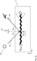
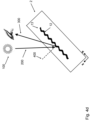
- the profile shape, the grating period ⁇ and/or the relief depth t of the at least one first relief structure is selected in particular such that, in at least one first angle of incidence and/or reflection, a colored, in particular a golden or copper, first color impression is created in direct reflection in the at least one partial area of the at least one first area in which the metal layer is arranged.
- the light incident at least at a first angle of incidence and directly reflected by the at least one metal layer having the relief structure or directly transmitted through the at least one metal layer is changed, in particular changed by plasmon resonance of the at least one metal layer.
- the relief depth t is determined by the spacing of the maxima of the elevation of the at least one first relief structure from the base surface in a direction perpendicular to the base surface.
- the grating period ⁇ corresponds to the spacing in the x-direction or y-direction between the maxima of two elevations or minima of two depressions, whereby these are only separated by one depression or elevation.
- the term "region" refers in particular to a defined area of a layer or film or plane or layer which, when viewed perpendicular to a plane formed by a layer, in particular by the at least one relief structure, is occupied.
- the functional element has the relief structure at least in a first region, but can also have further regions.
- the regions can be further divided into subregions and/or zones and/or zone regions.
- the x-direction and y-direction are the spatial directions which span the plane of the region.
- Layers can be arranged above and/or below other layers, whereby the terms below and/or above are understood to mean in particular the arrangement of layers in relation to another layer when viewed by an observer from a viewing direction. It is therefore expedient if the terms below and/or above represent a reference system.
- the viewing direction is preferably selected so that a layer is viewed perpendicular to a plane spanned by a layer. Deviations from this are expediently indicated with an angle in degrees to the normal.
- Plasmons are the quantized fluctuations of the charge carrier density in semiconductors and metals, and are treated as quasiparticles in quantum mechanics. Furthermore, the term plasmon is a common abbreviation for plasma oscillation quanta. Plasmon resonance in the functional elements according to the invention falls under the category of plasmon-polariton.
- Color or color or individual color or individual color is understood to mean a color location in a color space.
- the color space can be the CIELAB color space in particular.
- a different or differing color is understood to mean a color difference dE between two color locations in a color space.
- the color space can in particular be the CIELAB color space.
- a different color that is sufficiently perceptible to the human eye has a color difference dE in the CIELAB color space of at least 2, preferably at least 3, particularly preferably at least 5, more preferably at least 10.
- the color location is usually determined with a color measuring device, for example a "Datacolor 650" spectrophotometer.
- dE Delta E or ⁇ E
- the brightness value L* is perpendicular to the color plane (a*,b*).
- the a-coordinate indicates the color type and color intensity between green and red and the b-coordinate indicates the color type and color intensity between blue and yellow.
- L* can take values between 0 and 100 and a and b can vary between -128 and +127.
- the values for dE, L* a* and b* are unitless.
- the invention makes it possible to provide functional elements with an optical appearance that stands out clearly from the previously known silvery shiny and/or rainbow-colored hologram effects.
- the optical appearance of the functional element according to the invention is characterized by a defined and largely single-colored golden or copper first color impression, which can be seen under normal viewing conditions in direct reflection and/or transmission.
- the relief structure, in particular the metallized one is preferably embedded in a transparent polymer layer with a refractive index preferably in the range of approximately 1.4 to 1.6, in particular from 1.4 to 1.6, and/or is covered by such a polymer layer.
- the first colour impression is stable in direct reflection over a relatively wide tilt angle range of in particular at least 0° to 30° to the normal of the plane spanned by the functional element.
- the first colour impression is also perceived by the human eye as stable, i.e. as invariable when rotating the functional element around an imaginary axis of rotation, which is perpendicular to the axis of rotation of the at least one metal layer.
- the first color impression perceived by the human eye is independent or almost independent of the orientation of the lattice structure.
- the color impression described in this document is preferably created by the absorption of light of certain wavelengths in a metal layer.
- a metal layer is particularly more resistant to light-induced changes than organic compounds. This has the advantage that the fading known from organic dyes or color pigments as a result of irradiation with visible light or light with UV radiation does not occur in the color impression according to the invention.
- the color impression is particularly lightfast. Together with the color stability over a relatively wide tilt angle range and when rotating the functional element, the gold or copper-colored color impression is therefore particularly suitable as a lightfast reference color in a design or as a lightfast color standard.
- the invention also enables the production of more cost-effective functional elements compared to known functional elements with interference filters, for example Fabry-Perot filters.
- interference filters for example Fabry-Perot filters.
- the color effects that occur with the functional element according to the invention cannot be imitated using conventional holographic techniques and cannot be copied using dot matrix and Kinemax origination machines, so that this also further increases the security against counterfeiting.
- Such a combination makes it possible to create distinctive and difficult to imitate functional elements with multiple color impressions in adjacent surface areas, such as black, red, silver, gold and copper, whereby the corresponding surface areas and thus their color impressions are in perfect register with each other.
- Counterfeiters who aim to imitate such a functional element for example a security element, in particular comprising a combination of different areas by printing one or more additional colors,
- the optically variable color shift effect from the first color impression to the second color impression i.e.
- Registered or register or register-accurate or register accuracy or register accuracy means the positioning accuracy of two or more layers relative to one another.
- the register accuracy should be within a specified tolerance and as low as possible.
- the register accuracy of several elements and/or layers relative to one another is an important feature in order to increase process reliability and/or product quality and/or security against counterfeiting.
- Precise positioning can be achieved in particular by means of sensory, preferably optically detectable registration marks or register marks. These registration marks or register marks can either represent special separate elements or areas or layers or can themselves be part of the elements or areas or layers to be positioned.
- the profile shape of the at least one first relief structure is designed asymmetrically in the x-direction and/or y-direction.
- the profile shape of the at least one first relief structure is designed in particular not symmetrically in the x-direction and/or y-direction.
- the profile shape is designed continuously or stepwise, in particular over the relief depth t. varies. This offers the advantage that the profile shape of the at least one first preferably metallized relief structure creates a much more visible and clearer color impression for the human observer during typical viewing than, for example, symmetrical profile shapes.
- the exciting electric field is more strongly localized by the asymmetrical profile shape, for example at the narrow tips of the relief structure. This can lead to a more pronounced resonance and absorption. Furthermore, the excitation of the plasmons differs on both sides of the asymmetrical profile shapes, so that incident light generates a different effect depending on which of the surfaces the light is irradiated onto.
- Symmetrical profile shapes are, for example, sinusoidal, rectangular or binary.
- symmetrical profile shapes have a mirror symmetry if the base surface is used as a mirror plane.
- the profile shape remains the same in this mirroring, the relief structure is only shifted by half a grating period ⁇ .
- asymmetrical profile shapes do not have a mirror symmetry in the plane spanned by the base surface.
- the periodic variation of the at least one first relief structure is at least partially superimposed with a random and/or pseudo-random variation.
- the periodic variation of the at least one first relief structure at least in regions on a microstructure, in particular on a Fresnel lens and/or a Fresnel freeform surface and/or on micromirrors and/or on blaze gratings, in particular with a grating period of more than 5 ⁇ m, and/or on computer-generated hologram (CGH) structures.
- a microstructure in particular on a Fresnel lens and/or a Fresnel freeform surface and/or on micromirrors and/or on blaze gratings, in particular with a grating period of more than 5 ⁇ m, and/or on computer-generated hologram (CGH) structures.
- CGH computer-generated hologram
- optical effect of the microstructure itself or to combine the optical effects of both structures in addition to the optical effects of the at least one first relief structure, such as stable color impression, color shift effect and "latent effect".
- areas that are created by the microstructure such as Fresnel freeform surfaces, an optical curvature effect that virtually protrudes from the surface or recedes behind the surface, are not perceived achromatically, but as a gold-colored or copper-colored optical curvature effect of this kind.
- the first relief structure When a blaze grating structure, in particular with a grating period of more than 5 ⁇ m, i.e. with inclined macroscopic surfaces, is superimposed on the first relief structure, the first relief structure is tilted accordingly by the angle of the inclined macroscopic surface relative to a base surface, whereby this combined relief structure creates a color impression with a larger viewing angle range.
- a color gradient of the combined relief structure can also be realized when superimposed on the first relief structure.
- the values of the grating period ⁇ of the at least one first relief structure in the x-direction and/or y-direction are ⁇ ⁇ 300 nm, preferably ⁇ ⁇ 280 nm, preferably ⁇ ⁇ 260 nm.
- ⁇ , >, ⁇ and/or ⁇ correspond to the symbols commonly used in mathematical notation. Gratings with such a small grating period ⁇ are also referred to as subwavelength gratings.
- the values of the grating period ⁇ of the at least one first relief structure in the x-direction and/or y-direction are further preferably selected from a range from 150 nm to 260 nm, preferably from 180 nm to 250 nm.
- the values of the relief depth t of the at least one first relief structure in the x-direction and/or y-direction are t ⁇ 0.7 ⁇ , preferably t ⁇ 0.6 ⁇ .
- the numerical value before the grating period ⁇ is to be understood as a factor by which the grating period ⁇ is multiplied. If even deeper gratings are selected, this leads to a stronger absorption, which in turn results in a comparatively darker color impression.
- the values of the relief depth t of the at least one first relief structure in the x-direction and/or y-direction are t > 0.2 ⁇ , preferably t ⁇ 0.3 ⁇ . If the relief depth is lower, this has the effect that the excitation of the plasmons is weaker, whereby the resulting color saturation is only weakly pronounced and thus only a comparatively light color impression, in particular a pastel-like color impression, is achieved.
- the preferably asymmetrical profile shape of the at least one first relief structure is selected such that the width of the elevations and depressions of the at least one first relief structure, based on a distance of t/2 from the base area, is at least 60% of the grating period, preferably at least 70% of the grating period and/or at most 40% of the grating period, preferably at most 30% of the grating period.
- the distance of t/2 from the base area is also referred to as the half-width.
- the distance between adjacent flanks of the at least one first relief structure is thus determined at a relief depth of t/2.
- flank steepness of the at least one first relief structure based on a distance of t/2 from the base surface, has a value in the range of 60° to 90°, preferably of 70° and 85°.
- the flank steepness of the at least one first relief structure is understood to mean the angle enclosed with the base surface of a tangent to the flanks of the first relief structure at a distance of t/2 from the base surface of the first relief structure, i.e. halfway up the height of the first relief structure.
- the distance from the base surface is determined in a direction perpendicular to the base surface.
- flank steepness achieve the advantage that the strength of the color impression generated by the at least one first preferably metallized relief structure, in particular in direct reflection or direct transmission, is further improved.
- the flank steepness of the at least one first relief structure is selected with respect to each distance between 25% of the relief depth and 75% of the relief depth starting from the base area such that it has a value selected from a range of 40° to 90°, preferably from 50° to 85°.
- a value for the flank steepness of the at least one first relief structure based on each distance between 0% and 25% of the relief depth and/or between 75% and 100% of the relief depth starting in each case from the base area, which has a value selected from a range from 0° to 50°, preferably from 0° to 40°.
- the at least one first relief structure is preferably designed as a 2D grid, preferably as a cross grid and/or as a hexagonal grid or as a more complex 2D grid.
- More complex 2D grids are understood to mean, for example, 2D grids with a preferably slight stochastic variation of the grid period. This also includes 2D grids with a periodic arrangement over a length of at least four times the locally present grid period and at the same time a random arrangement over lengths of more than 100 ⁇ m. 2D grids have a sequence of elevations and depressions in the x-direction and y-direction.
- the grid period ⁇ of the sequence of elevations and depressions with respect to both directions is preferably selected in the range specified above.
- the grid period in the x-direction and y-direction is in particular the same.
- the grid period can also be different in both spatial directions.
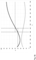
- the grating period ⁇ and/or the profile shape and/or the relief depth t of the first preferably metallized relief structure are designed such that the at least one first region for an angle of incidence or viewing angle of 0° to 30° has a direct reflection of the incident light that is at least 10% lower in at least 75% of the wavelength range from 400 nm to 500 nm compared to direct reflection in at least 75% of the wavelength range from 525 nm to 700 nm.
- the grating period ⁇ and/or the profile shape and/or relief depth t of the first preferably metallized relief structure are designed in such a way that the at least one first region has a reflection of the incident light that is at least 15% lower in at least 70% of the wavelength range from 400 nm to 500 nm compared to the reflection in at least 70% of the wavelength range from 525 nm to 700 nm, further preferred that the at least one first region has a reflection of the incident light that is at least 15% lower in at least 90% of the wavelength range from 400 nm to 500 nm compared to the reflection in at least 90% of the wavelength range from 525 nm to 700 nm and further preferred still further that the at least one first region has a reflection of the incident light that is at least 20% lower in at least 90% of the wavelength range from 400 nm to 500 nm compared to the reflection in at least 90% of the wavelength range from 525 nm to 700 nm.
- the at least one first region has a direct reflection of the incident light in at least 90% of the wavelength range from 525 nm to 700 nm of greater than 30%, preferably greater than 40%, more preferably greater than 50%, so that the first color impression does not appear to be too dark.
- the wavelength range from 400 nm to 500 nm corresponds in particular to the wavelength range of violet and blue light and the wavelength range from 525 nm to 700 nm corresponds in particular to the wavelength range of green, yellow, orange and red light.
- the above-mentioned design of the at least one first region, in particular with regard to the grating period ⁇ and/or the profile shape and/or relief depth t, thus results in the proportion of blue and/or cyan-colored reflected light being lower than the proportions of the remaining reflected light of the wavelength range visible to the human eye, preferably from 400 nm to 700 nm.
- the first color impression for a viewer appears in direct reflection with a golden or copper color tone.
- the values given above for direct reflection are in particular measured values from reflection spectra in a wavelength range from 400 nm to 700 nm.
- the reflection spectra are preferably determined with vertical illumination and observation using the AvaSpec-2048 spectrometer from Avantes.
- the illumination is carried out using the LS-1 white light source with a color temperature of 3100 °K from Ocean Optics via optical fibers.
- a precisely defined beam of light is directed vertically onto a surface and the light reflected back vertically is detected by an optical fiber.
- This fiber leads the light to the spectrometer, which measures how much light of which wavelength is reflected.
- the reflection is advantageously calibrated to 100% using standards.
- the dark reference is measured against a matt black surface and the white balance of the spectrometer is carried out against an aluminum mirror. 100% reflection therefore corresponds to the reflection of the aluminum mirror and 0% to the Reflection of the matt black surface.
- the measured reflection is therefore preferably a value from a range of 0% to 100%.
- the at least one metal layer is made of aluminum and/or silver and/or palladium and/or platinum and/or alloys thereof.
- the metal layer is made of aluminum or an alloy with an aluminum weight fraction of more than 70%, preferably more than 90%.
- the at least one metal layer is vapor-deposited and/or sputtered from the vacuum in the at least one first partial region of the at least one first region.
- the at least one metal layer can also be initially applied over the entire surface and then removed again in the regions that are not to have any metal. This can be done using known structuring methods or demetallization methods such as etching methods and/or washing methods and/or exposure methods.
- the at least one metal layer can be removed in regions in such a way that the remaining metal regions are in perfect register with regions in which structure-based effects are generated.
- the layer thickness of the at least one metal layer is selected such that it has an optical density (OD) selected from a range from 0.9 to 3.0, preferably from 1.1 to 2.5, more preferably from 1.6 to 1.9.
- OD optical density
- the at least one metal layer has an optical density (OD) selected from a range of 1.6 to 1.9.
- the optical density (OD) parameter refers to the transmission (T), i.e. the permeability of electromagnetic waves, particularly in the wavelength range from 400 nm to 700 nm, of a metal layer relative to an unstructured and thus smooth metal surface.
- T transmission
- OD optical density
- the reason for the increased transmission in at least one first region of the at least one first relief structure is probably due to increased plasmon excitation by the incident light, which is made possible by the relief structure.
- This makes it possible to provide a functional element according to the invention which shows at least one optically variable effect when viewed in reflected light and when viewed in transmitted light. It is also possible that, with an appropriate design, the optical effect when viewed in reflected light is different from the optical effect when viewed in transmitted light. Furthermore, with an appropriate design, it is possible that, when viewed in reflected light, the optical effect recorded when viewed from one side of the functional element is different from the optical effect recorded from another side. In other words, when viewed from the front or from the back in reflection, an observer can record an optical, preferably different, effect.
- the aforementioned layers can be arranged individually or in any combination with one another in the functional element, in particular in the at least one area, above and/or below the at least one first relief structure.
- the layers can be applied over the entire surface or only partially, i.e. in regions.
- one or more of the layers can be arranged in a pattern.
- Several pattern-shaped layers can also be arranged in register with one another. This advantageously increases the design variety of the functional element even further.
- the functional element is preferably designed such that one or more layers of the functional element possibly arranged above and/or below the at least one metal layer and/or one or more layers of the functional element possibly provided below the at least one metal layer are transparent or semi-transparent, in particular have a transmission, in particular in the wavelength range from 400 nm to 700 nm, of at least 10%, preferably of at least 25%, more preferably of at least 75%, even more preferably of at least 90%, in at least a partial region of the at least one first region.
- the color impression of the optical effect when viewed from the top and from the bottom, each in incident light, can be the same.
- the color impression of the optical effect can also be different, for example due to the profile shape of the first relief structure and/or due to different refractive indices of the respective material above or below the at least one metal layer.
- a different color impression of, for example, gold when viewed from the top and reddish when viewed from the bottom can be used for various functional elements such as, for example, for a rescue foil without the use of dyes or for radiation and/or heat management, for example in satellites or similar.
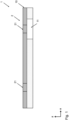
- the functional element according to the invention has, for example, a carrier film, preferably a transparent plastic film, preferably made of PET, PC, PE, BOPP with a thickness between 10 ⁇ m and 500 ⁇ m, a transparent replication layer, preferably made of a thermoplastic or UV-curable replication varnish, an adhesive layer, preferably a cold adhesive layer, a hot adhesive layer or a UV-curable adhesive layer and a polymer layer, preferably made of known varnish systems with a refractive index in the range from 1.45 to 1.55.
- a carrier film preferably a transparent plastic film, preferably made of PET, PC, PE, BOPP with a thickness between 10 ⁇ m and 500 ⁇ m
- a transparent replication layer preferably made of a thermoplastic or UV-curable replication varnish
- an adhesive layer preferably a cold adhesive layer, a hot adhesive layer or a UV-curable adhesive layer and a polymer layer, preferably made of known varnish systems with a refractive index in the range from 1.45 to 1.55.
- the functional element according to the invention preferably has no additional thin layers of high-refractive materials, which are arranged in particular above and/or below the at least one metal layer.
- Layers of high-refractive materials can be formed, for example, from ZnS or TiO 2.
- it can also be a high-refractive replication lacquer layer, for example a polymer lacquer layer, which is filled in particular with high-refractive nanoparticles.
- These special and expensive materials can also be dispensed with. Consequently, a functional element according to the invention can be integrated particularly cost-effectively into known product structures and thus manufactured cost-effectively.
- the functional element can have, particularly when viewed from the side facing a viewer, an at least partially present thin high-refractive layer, for example made of ZnS, on the metal layer.
- This at least partial high-refractive layer changes the color impression depending on the layer thickness, for example from gold or copper to red, since the plasmon resonance is changed.
- the high-refractive layer can be in the form of motifs such as letters, numbers, symbols, patterns, a geometric figure, etc., whereby these motifs appear differently colored compared to the gold or copper colored areas without the high-refractive layer.
- the thickness of the high-refractive layer is preferably selected from a range of 5 nm to 150 nm, more preferably from 10 nm to 50 nm.
- a dielectric layer for example made of a low-refractive material such as MgF 2 or a low-refractive polymer layer, is arranged above and/or below the at least one metal layer.
- the dielectric layer is preferably printed or vapor-deposited in such a way that it is arranged over the entire surface or in regions on the surface of the at least one metal layer.
- a dielectric and in particular low-refractive layer has in particular a refractive index of at most 1.45.
- the thickness of the dielectric and in particular low-refractive layer is preferably selected from the range from 5 nm to 2000 nm and more preferably from 10 nm to 500 nm.
- the preferably metallized relief structure is overlaid with a color filter in a known manner, for example by placing a separate color filter which has a distance of more than 1 ⁇ m, a viewer can see a color mixture from the overlay of the optical effect, in particular the color impression of the preferably metallized relief structure and the color filter function.
- the optical effect of the preferably metallized relief structure is thus practically colored by the color filter in the color tone of the color filter.
- the functional element has at least one dye and/or one luminescent substance in the first regions or in the at least one first region, which is arranged in particular in a layer.
- the dye and/or luminescent substance is preferably arranged less than 1 ⁇ m, more preferably less than 750 nm, even more preferably less than 500 nm, and even less than 300 nm away from one of the surfaces of the at least one metal layer.
- the dye and/or luminescent substance is preferably arranged in the dielectric layer or a polymer layer.
- the dye and/or the luminescent substance can be applied, for example, by means of a printing process or from a vacuum, e.g. by means of thermal vapor deposition.
- such a close arrangement of the dye and/or the luminescent substance on the surface of the at least one metal layer with the first relief structure causes a greatly increased absorption and/or fluorescence.
- the amplification mechanism is referred to as plasmon-enhanced absorption and plasmon-coupled emission. This distinguishes the first relief structure significantly, in particular, from mirror surfaces or "normal" diffractive structures in which this amplification effect does not occur.
- the dye and/or the luminescent substance can be applied or arranged over the entire surface or in regions, for example in the form of motifs that are recognizable to the human eye, such as letters, numbers, symbols, patterns, a geometric figure, etc.
- the dye and/or the luminescent substance is arranged only in regions on the at least one metal layer.
- the dye and/or the luminescent substance is only provided where the at least one metal layer borders on the at least one first relief structure and generates the effect described above.
- luminescent substance refers in particular to a fluorescent or phosphorescent substance.
- Typical fluorescent substances are excited by UV radiation in the range of 395 nm and/or 365 nm and/or 313 nm and/or 254 nm. Fluorescent substances are known which emit excitation in only one wavelength range or in several wavelength ranges, emitting the same or similar or different colors depending on the incident wavelength in the visible range.
- the dye and/or the luminescent substance can be applied by a printing process or from a vacuum.
- dyes applied from a vacuum are Patinal Black A or Brown A from Merck as well as light in the visible spectral range, preferably in the wavelength range from 400 nm to 700 nm, metals such as gold, copper or chromium that absorb light.
- metals such as gold, copper or chromium that absorb light.
- the metal layer there is preferably a very thin dielectric layer between the metal layer and the dye layer, for example the natural oxide layer of a vapor-deposited aluminum layer, which is a few nanometers thick.
- the thickness of this dielectric layer is between 2 nm and 10 nm. This ensures that in particular, the absorption properties of the dye layer made of a strongly absorbing metal are not adversely affected by the electrical connection to the metal layer.
- the dye and/or luminescent substance is preferably a soluble dye or luminescent substance or insoluble nanoparticles or pigments.
- Dyes from the following groups of substances are preferably used as dyes: metal complex dyes, in particular with Cr 3+ or Co 2+ as the central atom.
- Luminescent substances are preferably selected individually or in combination from the following groups of substances: coumarins, rhodamines, cyanines.
- the dye and/or the luminescent substance can have a variable absorption behavior that reacts to external influences.
- This variable absorption behavior can be reversible or irreversible and preferably causes a color change.
- a functional element according to the invention can have a sensor layer.
- the sensor layer is understood to mean in particular a preferably polymeric layer which has the dye and/or the luminescent substance which has an absorption behavior which reacts variably to external influences.
- variable dyes and/or luminescent substances that react to external influences are chromogenic materials, which change their colour or transparency depending on temperature (thermochromic materials), incidence of light (photochromic materials), electrical voltage and/or current, and pressure.
- thermochromic dyes and/or luminescent substances a predetermined temperature change in particular triggers the colour change and in the case of photochromic dyes, a predetermined radiation intensity in particular.
- a functional element according to the invention can be designed as a sensor element, in particular comprising a preferably polymeric sensor layer.
- a functional element according to the invention which preferably has a thermochromic dye and/or luminescent substance, can be used, for example, in the food industry in a time & temperature sensor (also called a time/temperature indicator (TTI)).
- TTI time/temperature indicator
- Such a sensor can, for example, indicate an interruption in the cold chain.
- Thermochromic dyes are usually substances that have a structural phase transition that is accompanied by a color change.
- An example of a thermochromic dye consists of a mixture of anthocyanidin dye chloride, dodecyl gallate and hexadecanoic acid as in J. Mater. Chem. C, 2013, 1, 2811-2816 described.
- a photochromic dye is bacteriorhodopsin.
- a functional element comprising a photochromic dye, in particular bacteriorhodopsin, can be used as a security element that changes color when irradiated with a sufficiently high intensity.
- a functional element can be a light intensity sensor element in a light intensity sensor.
- variable dyes and/or luminescent substances that react to external influences are pH-sensitive dyes and/or luminescent substances, which show different colors in aqueous solution depending on the pH value.
- Methyl orange, bromothymol blue or phenolphthalein are suitable examples. In aqueous solution they show different colors depending on the pH value. Phenolphthalein, for example, is transparent for pH values less than 8 and turns magenta at pH values of 9 and above. At a very high pH value close to 14 it becomes colorless again. At a very low pH value less than zero the indicator turns red-orange.
- a sensor layer comprising a dye and/or a luminescent substance that is pH-sensitive can be used, for example, as a pH sensor.
- variable dyes and/or luminescent substances that react to external influences are substances that react with substances, for example gaseous or liquid substances, whereby the reaction product to the dye and/or the luminescent substance has a different complex refractive index, absorption coefficient and/or color impression.
- substances for example gaseous or liquid substances
- perylene reacts with gaseous NO 2 so that this can be detected by a color change at sufficient concentration.
- the degree of pigmentation and/or the volume fraction of the dye and/or the luminescent substance can be up to 100% in the layer containing the dye and/or the luminescent substance, in particular if the dye is applied from a vacuum.
- the degree of pigmentation and/or the volume fraction of the dye and/or the luminescent substance is preferably more than 50%, more preferably more than 75%, and even more preferably more than 90%. With such high degrees of pigmentation and/or volume fractions of the dye and/or the luminescent substance, the dye layer can be made extremely thin, whereby the dye and/or the luminescent substance is as close as possible to the metal layer.
- the degree of pigmentation and/or the volume fraction of the dye and/or the luminescent substance of the layer containing the dye and/or luminescent substance, in particular applied by printing is less than 15%, preferably less than 10%, more preferably less than 5%, in particular when dyes and/or luminescent substances are used which, without a stabilizing matrix, e.g. made of polymer, do not have sufficient adhesion to the metal layer and/or would cause a chemical reaction with the metal layer.
- a stabilizing matrix e.g. made of polymer
- Mixtures of different pigments, dyes or luminescent substances can also be used.
- the layer containing the dye and/or the luminescent substance is preferably transparent and/or has a transmission, in particular in the wavelength range from 400 nm to 700 nm, of at least 10%, preferably of at least 25%, more preferably of at least 75%, even more preferably of at least 90%. This ensures in particular that even if the dye is applied in partial areas in which no relief structure according to the invention and/or no metal layer is arranged, no significant coloration of an underlying layer is recognizable.
- the generated first color impression can be specifically changed, particularly in direct reflection.
- the dye and/or the luminescent substance it is possible for the dye and/or the luminescent substance to have an absorption maximum at a wavelength of 550 nm, wherein the absorption has a Gaussian distribution with a width selected from a range of 25 nm to 100 nm, preferably from 40 nm to 60 nm. Since this would lead to a deep dip in reflection at 550 nm, arranging such a dye and/or luminescent substance results in a reddish first color impression.
- Gold nanoparticles with a diameter of approx. 20 nm have an absorption maximum at approx. 520 nm.
- the dye and/or the luminescent substance can be applied over the entire surface or only partially in individual surface areas. By applying them partially to certain surface areas, the first color impression can only be observed in the surface areas with dye and/or luminescent substance, and the first color impression is not present in the adjacent areas where no dye and/or luminescent substance is applied. This makes it possible to create designs that create a contrast between the first color impression and other optical effects.
- photochromic dyes and/or luminescent substances for example, color-stable areas with the first color impression as a reference color can be created in addition to areas that show the color change when irradiated, for example.
- the first color impression before the color change is essentially the same or different to the color impression of a area that does not have a chromogenic dye.
- the first color impression of the partial area having a chromogenic dye and/or luminescent substance is preferably different from the color impression of the partial area having no dye and/or luminescent substance after the color change.
- At least one translucent color layer is arranged at least in regions or over the entire surface of the at least one first region and/or further regions.
- This translucent color layer can directly adjoin the metal layer or be spaced apart from the metal layer by a dielectric intermediate layer.
- the at least one translucent color layer acts as a color filter and creates a perceivable color impression for a viewer in the corresponding color of the color filter.
- the translucent Color layer at a correspondingly small distance from the metal layer of preferably less than 1 ⁇ m, more preferably less than 750 nm, even more preferably less than 500 nm, furthermore still less than 300 nm, also as described above, change the first color impression through greatly increased absorption and/or fluorescence by means of plasmon-enhanced absorption and plasmon-coupled emission.
- the color impression of the first relief structure and/or the further relief structures and/or the mirror surfaces beneath the translucent color layer that can be perceived by a viewer can be determined as a combination of the optical effects of the corresponding relief structures and/or mirror surfaces with the coloring by the translucent color layer.
- the at least one translucent color layer is transparent and/or has a transmission, in particular in the wavelength range from 400 nm to 700 nm, of at least 10%, preferably of at least 25%, more preferably of at least 75%, even more preferably of at least 90%.
- Two or more translucent layers of paint can be present next to each other.
- two or more translucent layers of paint can overlap at least in some areas.
- a mixed color is formed from the colors of the two or more layers of paint and in particular the at least one first area underneath.
- the thickness of the at least one translucent color layer is preferably less than 10 ⁇ m, preferably less than 5 ⁇ m, more preferably less than 2 ⁇ m.
- the degree of pigmentation and/or the volume fraction of the dye and/or luminescent substance of the translucent color layer is less than 15%, preferably less than 10%, more preferably less than 5%.
- the dyes of the translucent color layer are preferably soluble dyes.
- the at least one translucent color layer can be arranged at a distance from one of the surfaces of the at least one metal layer of less than 500 nm, preferably less than 200 nm, even more preferably in direct contact with one of the surfaces of at least one metal layer.
- the at least one first region may have a partial region that is patterned and in particular has a partial region surrounding this partial region.
- at least one layer, in particular a mask layer can be arranged in the surrounding partial region, which is opaque, so that the optical effect generated by the at least one metal layer and the at least one first relief structure is only visible in the partial region of the at least one first region that is not covered by the opaque layer. In this way, interesting optical effects can be achieved by shaping the partial regions.
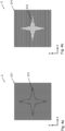
- the profile shape and/or the relief depth and/or grating period of the at least first relief structure is further selected such that, at a second angle of incidence different from the first angle of incidence, the colored appearance of the light directly reflected in the at least one first region or directly transmitted through the at least one metal layer is changed differently.
- a first color impression is shown in direct reflection at a first angle of incidence and a second color impression is shown in direct reflection at a second angle of incidence, wherein, in particular starting from the normal perpendicular to the base plane of the relief structure, the first angle of incidence is selected from a range from 0° to 30° and in particular wherein the second angle of incidence is increased by a value selected from a range of 10° to 45°, is greater than the first angle of incidence.
- the second angle of incidence is a value selected from a range of 30° to 60°. This enables a defined color change when tilted or a color shift effect. This means that under the first or second angle of incidence, when viewed with incident light and/or transmitted light, the human observer can see, in particular, different, stable color impressions in direct reflection.
- the second color impression depends on the azimuth angle.
- a functional element can be designed in such a way that it has a first region which has an azimuth angle of at least 15°, preferably 30° and more preferably 45°, rotated or different from a further first region.
- a second color impression can be generated which is different from the second color impression at an azimuth angle of, for example, 45°. Since the color shift effect is structure-based, it is in perfect register with other structure-based effects. A particular advantage of this effect is that in both first regions, with the same profile shape, relief depth or grating period, the same first color impression is created regardless of the selected azimuth angle.
- first viewing angle for example 10°
- second viewing angle for example 40°
- the color impressions in the areas differ depending on the grid orientation, i.e. depending on the azimuth angle in the respective area, and hidden information is only visible at this second viewing angle.
- Such a color effect is also called a metameric color effect.
- the azimuth angle is understood to mean in particular the orientation of a relief structure in the plane spanned by the base surface, where the x-direction corresponds to 0° and the y-direction to 90°.
- the orientation of a A relief structure can be rotated by a defined angle in relation to another relief structure, to whose base the x-direction and the y-direction are fixed.
- the light diffracted in the at least one first region into the first diffraction order produces an optical phenomenon which is different from the optical phenomena of the first and second angles of incidence.
- This optical phenomenon is referred to as the latent effect and corresponds to the illumination of the first diffraction order.
- the functional element has at least one second region, wherein in the at least one second region at least one second relief structure and/or a mirror surface without a relief structure formed in this mirror surface is formed.
- the at least one second relief structure is a relief structure which is preferably selected individually or in combination and/or in superposition from: diffractive relief structure, holographic relief structure, in particular 2D, 2D/3D or 3D hologram, matt structure, micromirror surface, reflective facet structure, refractive, almost achromatic microstructure, preferably blaze grating with a grating period of more than 5 ⁇ m, lens, microlens grid, binary random structure, binary Fresnel-shaped microstructure.
- a metal layer is arranged in a partial region of the at least one second region, which can preferably be designed analogously to at least one of the preferred embodiments of the metal layer in the at least one partial region of the first region.
- the at least one second relief structure is thus designed such that the at least one second region, in particular under diffuse lighting preferably appears silver and/or in the natural color of the metal which is arranged in the at least one second region and/or in which the at least one second relief structure is embossed.
- a diffractive relief structure is understood to mean, in particular, a relief structure which has a spatial frequency selected from a range of 200 lines/mm to 2000 lines/mm and which generates an optically variable effect in particular by diffraction of the incident light into the first or a higher diffraction order.
- These optically variable effects can be, for example, rainbow-like color effects and/or movement effects and/or pumping effects and/or transformation effects.
- Examples of diffractive relief structures include, for example, line gratings or cross gratings.
- diffractive relief structures can also be formed by computer-generated holograms, for example by kinoforms.
- Matt structures can be used as isotropically scattering or anisotropically scattering matt structures.
- a matt structure is a structure with light-scattering properties, which preferably has a stochastic or random surface profile. Matt structures preferably have a relief depth t in the range from 100 nm to 5000 nm, preferably from 200 nm to 2000 nm. Furthermore, matt structures preferably have an average roughness value R a selected from a range from 50 nm to 2000 nm, preferably from 100 nm to 1000 nm. The matt effect can be either isotropic or anisotropic.
- a microstructure is a structure whose spatial frequency is less than 200 lines/mm or whose grating period is greater than 5 ⁇ m and which generates an optical effect essentially through refraction. The effect is therefore almost achromatic.
- Lenses can be designed as refractive lenses or as refractive concave mirrors or also as diffractive lenses or diffractive concave mirrors.
- a microlens grid is preferably formed by a one-dimensional or two-dimensional arrangement of microlenses, for example of cylindrical lenses in a one-dimensional arrangement of the microlenses or of microlenses with a spherical or approximately spherical or aspherical shape in a two-dimensional arrangement of the microlenses.
- the grid width of a microlens grid preferably has a value selected from a range of 5 ⁇ m to 300 ⁇ m, more preferably from a range of 5 ⁇ m to 50 ⁇ m.
- the functional element has at least one third region, wherein at least one third relief structure is formed in the at least one third region.
- the at least one third relief structure is in particular a relief structure which comprises gratings with a grating period ⁇ of less than 500 nm and more than 300 nm and a relief depth t of more than 150 nm.
- the at least one third region is designed in such a way that in direct reflection over a relatively wide tilt angle range of in particular at least 0° to 30° to the normal of the plane spanned by the functional element it preferably has a red or a dark color impression, in particular a black color impression, in direct reflection or in transmission.
- a metal layer is arranged in a partial region of the at least one third region, which can preferably be designed analogously to at least one of the preferred embodiments of the metal layer in the at least one partial region of the first region.
- the optical effects such as the colour impression of the different areas are essentially generated by structures, in particular the at least one first area, the at least one second area and the at least one third area can be arranged in register with each other, since the Arranging additional layers of varnish for a colorful design can be dispensed with.
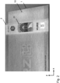
- the color stability when the functional element is tilted in combination with the perfect register of the color impression in direct reflection of the corresponding different areas to each other can be used for the detection and/or recognition and/or verification of the functional element in machine, particularly automated processes such as "optical machine authentication” and "optical phone authentication".
- the reading devices used for this can be stationary or mobile.
- Stationary reading devices such as those used for passport control at airports or at border crossings, often have the option of recording the passport page with the security elements under diffuse lighting.
- the areas exhibiting the color impression according to this invention appear very high-contrast in the image recording, whereby the register accuracy of the color impression relative to silver-appearing areas can be verified by means of a suitable image analysis.
- Mobile reading devices such as smartphones with suitable software, can also generate images that can be used to verify the register accuracy of different image elements relative to one another.
- the software preferably instructs the user to optimize the lighting so that the verification is possible as best as possible.
- the at least one first region, the at least one second region, the at least one third region or at least one of the first, second or third regions has a pattern-like shape.
- a region can be formed, for example, in the form of letters, numbers, a symbol, a geometric figure or a motif.
- the at least one first region can be designed as a mini-text or micro-text.
- Text is preferably understood to be a sequence of two or more letters, symbols or numbers, with a minitext preferably having a font height in the range of 0.5 mm to 2.5 mm and a microtext preferably having a font height in the range of 0.125 mm to 0.5 mm. Texts with font heights of less than 0.125 mm are understood to be nanotext.
- first and/or second and/or third regions can be arranged as a plurality of pixels.
- the pixels can be round, square, hexagonal, motif-shaped or in another connected shape.
- the pixels can also have an elongated shape, in particular a line shape.
- the maximum extent of a pixel in at least one of the spatial directions, preferably in the x-direction and y-direction, is preferably less than 300 ⁇ m, preferably less than 100 ⁇ m, more preferably less than 10 ⁇ m, even more preferably less than 5 ⁇ m, and even more preferably less than 3 ⁇ m.
- a pixel is larger than 1 ⁇ m, preferably larger than 1.5 ⁇ m, in the x-direction and/or y-direction.
- Protruding dimensions of the pixels offer the effect of high resolutions of the information displayed. This allows stronger optical effects to be achieved, for example movement effects over greater distances.
- the dimensions of the pixels are large enough that the at least one relief structure of the at least one first area still has a has a sufficient number of grating periods so that it can still generate its optical effect.
- At least one translucent color layer in particular over the entire surface or partially, is arranged behind and/or below the at least one first region and/or second region and/or third region and/or further regions, at least in some regions or over the entire surface in the viewing direction of an observer, in particular perpendicular to the plane spanned by the functional element.
- At least one translucent color layer is arranged in the viewing direction of an observer, in particular perpendicular to the plane spanned by the functional element, at least in some areas or over the entire surface below the at least one first relief structure, the at least one second relief structure, the at least one third relief structure and/or at least one mirror surface and/or the metal layer. It is possible for the at least one translucent color layer to be arranged in the viewing direction of an observer, in particular perpendicular to the plane spanned by the functional element, in such a way that it completely or partially overlaps with the at least one first, second and/or third region. It is also possible for at least one translucent color layer not to overlap with the at least one first, second and/or third region.
- the at least one translucent color layer can directly adjoin the metal layer or be spaced apart from the metal layer by a dielectric intermediate layer.
- the at least one translucent color layer preferably acts as a colored background and thus as an optically contrasting area and creates a perceptible color impression in the corresponding coloring of the at least one color layer, especially for a viewer.
- the at least one translucent color layer in particular in direct reflection over a tilt angle range of preferably at least 0° to 30° to the normal and/or over a tilt angle range of preferably at least 30° to 60° to the normal, in particular in the CIELAB color space, has a total color level dE of 50 to 270, preferably from 100 to 270, more preferably from 130 to 270, to the first and/or to the second and/or to the third region, in particular to the at least one partial region of the at least one first, second and/or third region in which a metal layer is arranged.
- the at least one translucent color layer in particular in direct reflection over a tilt angle range of preferably at least 0° to 30° to the normal and/or over a tilt angle range of preferably at least 30° to 60° to the normal, has a darker color, in particular with a lower brightness value L, in particular in comparison to the at least one first and/or second and/or third region, and the at least one first and/or second and/or third region has a lighter color, in particular with a higher brightness value L, in particular in comparison to the at least one translucent color layer.
- the at least one translucent color layer in particular in direct reflection over a tilt angle range of preferably at least 0° to 30° to the normal and/or over a tilt angle range of preferably at least 30° to 60° to the normal, has a lighter color, in particular with a higher brightness value L, in particular in comparison to the at least one first and/or second and/or third region, and the at least one first and/or second and/or third region has a darker color, in particular with a lower brightness value L, in particular in comparison to the at least one translucent color layer.
- a first color is understood to be lighter compared to a second color if the first color has a higher brightness value L compared to the second color.
- a third color is preferably understood to be darker compared to a fourth color if the third color has a lower brightness value L compared to the fourth color.
- first region and/or the second region in particular in direct reflection over a tilt angle range of preferably at least 0° to 30° to the normal and/or over a tilt angle range of preferably at least 30° to 60° to the normal, in particular in the CIELAB color space, have a total color difference dE of 50 to 270, preferably from 100 to 270, more preferably from 130 to 270, to the third region, and/or if the first region and/or the second region, in particular in direct reflection over a tilt angle range of preferably at least 0° to 30° to the normal and/or over a tilt angle range of preferably at least 30° to 60° to the normal, have a lighter color, in particular with a higher brightness value L, preferably in comparison to the third region, and the third region, in particular in direct reflection over a tilt angle range of preferably at least 0° to 30° to the normal and/or over a tilt angle range of preferably at least 30° to 60° from the normal, has a darker
- first and/or second and/or third regions can also be arranged in a grid arrangement. It is also possible for the first and/or second and/or third regions to be interlaced. This means that first and/or second and/or third regions are arranged alternately one after the other and in particular directly adjacent to one another.
- the first and/or second and/or third regions have a small distance and/or Dimension at least in one dimension of less than 300 ⁇ m, preferably less than 100 ⁇ m.
- the at least one first region is designed such that it is arranged in at least two, preferably at least three, preferably at least five zones.
- the zones are preferably designed such that they are at least partially arranged more than 300 ⁇ m, preferably at least 1000 ⁇ m, apart from one another in the x-direction and/or y-direction, so that they are perceived as separate from one another by the human eye.
- one, preferably each, of the zones has at least one first zone region which is smaller than 2 mm, preferably smaller than 1 mm, more preferably smaller than 0.7 mm, in at least one spatial direction. It can be advantageous here for the at least one first zone region to make up at least 20%, preferably at least 30%, more preferably more than 50% of the area of an individual zone.
- At least one zone can have at least one second zone region which is larger than 2 mm, preferably larger than 3 mm, more preferably larger than 5 mm in at least one spatial direction, in particular wherein the area of the second zone regions of all zones is at least in total larger than 20 mm 2 , preferably larger than 30 mm 2 , more preferably larger than 50 mm 2 .
- This minimal area of the more extensive zone regions makes it easier for a viewer to reliably perceive the golden or copper color impression.
- the extent of at least one zone is also possible for the extent of at least one zone to be reduced in one spatial direction, preferably continuously or gradually tapering. This guides the viewer's eye to look from the more easily perceivable, wider second zone areas to the narrower first zone areas. In these areas, the perfect register of at least one first zone area to the other areas, sub-areas or zones of the functional element is more difficult for counterfeiters to imitate.
- the at least one first region can only be partially framed or even completely enclosed by the at least one third region, wherein the at least one third region has an extension in one of the spatial directions selected from a range of 30 ⁇ m to 1 mm, preferably from 50 ⁇ m to 300 ⁇ m, more preferably from 50 ⁇ m to 150 ⁇ m.
- the at least one third region thus forms a contour-like frame or partial frame that frames or surrounds the at least one first region partially or completely.
- the optical effects in the first, second and third regions have as different colors as possible from one another and thus as good an optical contrast as possible.
- a second region can have a Fresnel free-form surface, wherein this second region is enclosed by a first region with the first relief structure with the golden color impression.
- the at least one first region can be partially framed or even completely enclosed by at least one second region, wherein the at least one second region has an extension in one of the spatial directions selected from a range of 30 ⁇ m to 1 mm, preferably from 50 ⁇ m to 300 ⁇ m, more preferably from 50 ⁇ m to 150 ⁇ m.
- the at least one second region can be partially framed or even completely enclosed by at least one third region, wherein the at least one third region can be designed as in the previous paragraph.
- the at least one second region can have a microtext or nanotext.
- Such a design ensures that the optical effect of the at least one second region draws the viewer's attention to the region around the contour and thus to the perfect register between the regions or contours that appear different in direct reflection.
- a plurality of microlenses can be arranged in a grid above the at least one first region.
- "arranged in a grid” is understood to mean an arrangement in a grid.
- the microlenses are arranged in such a way that the at least one first region is perceived enlarged by an observer. In other words, the at least one first region lies in the focal plane of the microlenses.
- the microlenses can each have a cylindrical or lenticular or a spherical or approximately spherical shape or aspherical shape or other shapes.
- a microlens grid can have several microlens sub-grids, wherein preferably within a microlens sub-grid the microlenses are arranged as cylindrical lenses in a one-dimensional arrangement of the microlenses or microlenses with a spherical or approximately spherical or aspherical shape are arranged in a two-dimensional arrangement of the microlenses.
- a microlens grid in particular several different microlens sub-grids can be arranged. For example, within a microlens grid at least one microlens partial grid with a two-dimensional arrangement of the microlenses and at least one microlens partial grid with a one-dimensional arrangement of the microlenses can be provided.
- microlens partial grids can have a different external shape, in particular triangular, polygonal, round, elliptical, motif-shaped, pattern-shaped, in the form of a code.
- these microlens partial grids with one-dimensional or two-dimensional arrangements of microlenses each have the same grid width and/or the same focus length.
- the at least one first region is arranged in subregions such that the subregions produce a plurality of microimages or moiré icons arranged in a grid, in particular wherein these microimages or moiré icons are arranged in register with the plurality of microlenses arranged in a grid.
- the grid width of a grid of the microimages or moiré icons preferably has a value selected from a range of 5 ⁇ m to 300 ⁇ m, more preferably from a range of 5 ⁇ m to 50 ⁇ m.
- the grid of microimages or moiré icons has in particular an identical or slightly different, in particular different, grid width compared to the grid width of the microlens grid.
- the grid of microimages or moiré icons can be arranged slightly rotated, in particular rotated, relative to the microlens grid or alternatively have a largely identical, in particular identical, alignment to the microlens grid, i.e. have practically no rotation relative to the microlens grid.
- the grid of microimages or moiré icons can, corresponding to the microlens grid, have several sub-grids, whereby within a sub-grid the microimages or moiré icons are arranged in a one-dimensional Arrangement of the microimages or moiré icons are arranged or are arranged in a two-dimensional arrangement of the microimages or moiré icons.
- several different partial grids can be arranged within a grid of the microimages or moiré icons.
- at least one partial grid with a two-dimensional arrangement of the microimages or moiré icons and at least one partial grid with a one-dimensional arrangement of the microimages or moiré icons can be provided.
- the partial grids can have a different external shape, in particular triangular, polygonal, round, elliptical, motif-shaped, pattern-shaped, in the form of a code.
- the microimages or moiré icons can be designed within a partial grid in such a way that an optical effect associated with the partial grid is created for each partial grid.
- Several sub-grids can thus produce different optical effects, which together produce a combined optical effect in the grid of microimages or moiré icons or produce separate optical effects that exist side by side.
- the microimages or moiré icons can have, in particular, differently designed first regions and/or second regions and/or third regions and/or translucent color layers in front of and/or behind the first regions and/or second regions and/or third regions, in particular when viewed perpendicular to the plane spanned by the functional element, per partial grid.
- microimages or moiré icons for these different optical effects can have, in particular, a different number of first areas and/or second areas and/or third areas and/or translucent color layers in front of and/or behind the first areas and/or second areas and/or third areas, in particular in viewed perpendicular to the plane spanned by the functional element.
- Microimages are understood here to mean complete motifs and also incomplete motifs, i.e. fragments of motifs.
- a motif can be selected in particular or a combination of: image, symbol, logo, coat of arms, flag, portrait, alphanumeric character.
- the subregions are constructed from a plurality of pixels, wherein the pixels are designed as already described above.
- the subregions can comprise a plurality of pixels formed from the at least one second region and/or the at least one third region.
- the subregions preferably have pixels comprising the at least one first region and/or pixels comprising the at least one second region and/or pixels comprising the at least one third region.
- this makes it possible to create microimages with different colors and/or microimages with a high achromatic contrast between the foreground and background of a motif.
- this makes it possible to create microimages comprising pixels with a light white or silver color, dark gray or black color and/or a gold or copper color.
- the partial areas can also be designed by the arrangement of the pixels in such a way that a gradual transition from an increased arrangement of pixels comprising the at least one first area to an increased arrangement of pixels comprising the at least one second area is achieved. This enables a recognizable gradual transition from a golden or copper appearance to a silver appearance.
- the pixels can also have an elongated shape, in particular a line shape.
- the golden or copper color tone of a partial area lighter i.e. closer to the silver color tone.
- This can be achieved by arranging the plurality of pixels that do not comprise at least one third area as a mixture, preferably a stochastic distribution, of pixels comprising the at least one first area and the at least one second area.
- a motif of the microimage or a motif of moiré icons can be constructed in one zone from pixels with a silver reflective appearance and from pixels with a dark gray to black appearance, and in another zone of the motif can be constructed from pixels with a golden or copper appearance and pixels with a dark gray to black appearance.
- areas of the motif of the microimage or the motif of moiré icons can be constructed from pixels comprising the at least one second area and from pixels comprising at least one third area, and in another area of the motif from pixels comprising at least one first area and pixels comprising at least one third area.
- the at least one translucent color layer is arranged in particular above the at least one first, second and/or third region and below the plurality of microlenses.
- a motif is formed by a plurality of pixels comprising at least the first region and by a plurality of pixels comprising at least the at least one third region.
- the distribution of the pixels is thus designed in such a way that the motif is perceived by a viewer in direct reflection as a gold-colored grayscale image, in particular as a halftone image.
- the functional element according to the invention also offers the effect that the grayscale image or the halftone image has a color shift effect in direct reflection or in zeroth diffraction order.
- the functional element also offers another surprising latent effect in the first diffraction order with strong tilting, in particular in at least the first regions.
- An alternative variant for producing a gold-colored grayscale image, particularly as a halftone image consists in providing pixels in a flat first area using a high-resolution demetallization process, whereby the metal is removed in this first area. This can be done using known structuring processes or demetallization processes such as etching processes and/or washing processes and/or exposure processes. By backing both the metal layer and the demetallized areas with an at least partially flat color layer, the grayscale image can then be made visible with good contrast. Color mixing effects are also possible here.
- the at least one first region can be arranged in a first electrode layer.
- the first electrode layer is arranged in a reflective display or can be used in a reflective display.
- the first electrode layer can comprise further layers or functional elements, such as electrically conductive connection components and/or electromagnetic shields and/or thermal shields and/or optical shields and/or circuits.
- the first electrode layer has the optical effects generated by the at least one first region.
- a switchable layer for example an electrochromic layer or a liquid crystal layer or a PDLC (polymer dispersed liquid crystal) layer
- This switchable layer is characterized by the fact that its appearance can be changed by applying a voltage.
- a PDLC layer for example, appears cloudy to an observer or appears transparent as long as a voltage is applied.
- the thickness of the switchable layer is typically in the range of 2 ⁇ m to 20 ⁇ m.
- a second electrode layer can be arranged above the first electrode layer and/or the switchable layer.
- the second electrode layer is preferably transparent or semi-transparent and/or transparent and/or has a transmission, in particular in the wavelength range from 400 nm to 700 nm, of at least 50%, preferably of at least 75%, more preferably of at least 90%.
- a transparent second electrode layer are a printed poly(3,4-ethylenedioxythiophene) polystyrene sulfonate (PEDOT:PSS) layer or a structured, preferably finely structured, metal layer that appears transparent to the human eye.
- such a finely structured metal layer can consist of a metal net and/or a metal grid, which is made up of metal tracks that are approximately 5 nm to 100 nm wide and run in the x and y directions and are spaced apart from one another by, for example, 50 nm to 1000 nm.
- the entire surface of the metal network is electrically connected at the intersection points of the network.
- the first electrode layer is expediently arranged below the second electrode layer.
- the first electrode layer is arranged on the side of the second electrode layer facing away from an observer.
- the switchable layer is arranged between the first and second electrode layers.
- the optical effect of the switchable layer can be combined with the color effect of the lower electrode layer.
- a reflective display with a switchable layer for example a PDLC layer
- the golden or copper color impression of the first electrode layer is visible or at least more strongly visible, in particular in a partial area of the display which switches from cloudy to transparent when an electrical voltage is applied.
- the at least one first region is essentially not visible or at least only slightly visible. This results in a functional element in a reflective display which is essentially only recognizable to a viewer as long as a corresponding voltage is applied to the reflective display.
- the switchable layer can have a dye and/or be colored, giving it a color filter function in addition to the optical switching function.
- This offers the advantage that when voltage is applied to the switchable layer, the appearance changes from the color of the dye to the gold or copper color of the lower electrode layer when voltage is applied. This increases the design options even further.
- the degree of pigmentation and/or the volume fraction of the dye of the switchable layer is less than 15%, preferably less than 10%, more preferably less than 5%.
- the dye of the switchable layer is a soluble dye or insoluble nanoparticles.
- the functional element is designed as a sensor element, for example for detecting a substance to be detected and/or the change in environmental conditions such as pressure, temperature, incidence of light, electrical voltage and/or current.
- a preferably polymeric sensor layer is arranged on the side of the metal layer facing the viewer.
- the sensor layer is designed as already explained above.
- the dye and/or luminescent substance is arranged in the sensor layer, the dye preferably being chromogenic, preferably thermochromic and/or photochromic and/or pH-sensitive.
- the sensor layer changes its refractive index and/or absorption coefficient in the sensor area when it comes into contact with a sufficient amount of the substance to be detected.
- the amplification mechanism is called plasmon-enhanced absorption.
- the change in the color impression that is perceptible to the human eye is significantly greater in comparison to a metal layer with the sensor layer that does not have a relief structure.
- a preferably dielectric contrast layer to be arranged in regions above the sensor layer, as seen by an observer, so that it preferably covers at least partial regions of the sensor layer and prevents contact with the substance to be detected and/or the influence of changes in the ambient conditions.
- the contrast layer preferably has a refractive index that is close to the refractive index of the medium that contains the substance to be detected.
- the refractive index of the contrast layer preferably differs by up to ⁇ 10%, more preferably by up to ⁇ 5%, and even more preferably by up to ⁇ 2% from the refractive index of the medium that contains the substance to be detected.
- the region in which the at least one first relief structure, the metal layer and the sensor layer, but not the contrast layer, are preferably arranged forms a sensor area which is preferably in contact with the medium containing the substance to be detected and/or is exposed to the influence of the change in the ambient condition.
- this contrast layer is to protect the covered areas of the sensor layer from contact with the substance to be detected and/or from the influence of the ambient conditions so that these areas do not show the change in color impression triggered by the substance to be detected.
- the contrast layer therefore offers the advantageous effect that the contrast between the areas with and without color change is particularly easy to perceive for the human eye.
- the functional element prefferably has a filtering transparent layer, in particular an open-pored layer, which, as seen by an observer, is arranged above the sensor layer.
- the filtering layer is arranged in particular in the sensor area.
- the filtering layer is particularly suitable for the The layer is permeable to the substance to be detected and prevents other substances present in the medium from reaching the sensor layer. This also makes it possible to reduce or prevent unwanted reactions of the sensor layer with other substances also present in the medium.
- a sealing layer preferably made of polymer, is optionally provided, which prevents the medium from escaping at the edges of the sensor element.
- the sealing layer preferably made of polymer, is therefore not permeable to the medium and is preferably chemically inert towards the medium.
- the functional element prefferably has a vertically running channel, preferably in the form of a microfluidic device.
- the channel is preferably formed by the preferably polymeric sealing layer and can optionally be sealed by another preferably polymeric sealing layer.
- the polymeric sealing layer is preferably transparent. This allows the medium in the channel to be guided past the sensor area.
- the production of a functional element can be realized as follows.
- the first relief structure can be created on a glass substrate using known methods such as holographic two-beam exposure or using e-beam lithography.
- a nickel shim with the first relief structure can be obtained from this using a galvanic copying process according to the known state of the art.
- the nickel shim can be duplicated using known methods and the first relief structure can then be produced in a flexible film using a roll-to-roll process, for example thermal replication or UV replication.
- the first relief structure is realized on a rigid substrate, for example a glass substrate or a quartz substrate.
- a rigid substrate for example a glass substrate or a quartz substrate.
- the first relief structure can be copied from the nickel shim in a UV copying process directly onto the rigid substrate, for example a glass substrate or quartz substrate.
- sol-gel materials such as Ormocer, which are applied to the rigid substrate in liquid form.
- the nickel shim is then placed on the rigid substrate, for example the glass substrate or the quartz substrate, so that a thin film of the sol-gel material remains between the rigid substrate and the nickel shim.
- the sol-gel material is then hardened using UV radiation through the rigid substrate, for example the glass substrate or quartz substrate, and the nickel shim is removed.
- the metal layer can then be evaporated or sputtered from the vacuum onto the surface of the hardened sol-gel layer with the first relief structure.
- the sensor layer can then be applied to the metal layer as a thin layer, for example by spin coating.
- a partial area of the functional element in particular the at least one first area, can preferably be embossed onto a substrate using a pattern-shaped embossing stamp. It is also possible for the functional element to be applied to the entire surface of a substrate using a non-specific laminating roller. It is also particularly advantageous here if the surface of the substrate onto which the functional element is embossed has a surface structure, for example a matt structure, and the embossing pressure is selected such that the base area of the first relief structure is deformed according to the surface structure during embossing.
- the embossing pressure is selected so that the base area of the first relief structure is deformed according to the surface structure of the blind embossing tool when the blind embossing tool is pressed on.
- This method also makes it possible to subsequently individualize the functional element in a subsequent work step by appropriately deforming the base area of the at least one first relief structure and thus to introduce the additional optical effects already described above into the functional element or into a product that has the functional element.
- the use of the functional element in a product has proven to be particularly good.
- the functional element in the product can be arranged so that it is viewed from above, but also above a window area so that it can be viewed from above and through.
- FIG. 1 a sectional view of an exemplary product 1 comprising a functional element 2 is shown.
- Fig. 2 again shows an embodiment of a product 1 comprising a functional element 2, for example according to the sectional view of Fig. 1 .
- product 1 comprising a functional element 2 according to Fig. 1 or Fig. 2
- product 1 is, for example, an ID document, a label for product security or decoration, an ID card or credit card, a cash card, a hang tag of a commercial product or a certificate, in particular a software certificate, packaging, a component for stationary and/or mobile devices, an injection-molded component, a directly structured aluminum component, a motor vehicle, a decorative strip, a color filter, a sensor, an optical component, a light control system.
- the following statements are therefore not limited to a banknote, but can also be applied to the other above-mentioned embodiments of product 1.
- the product 1 comprises a carrier substrate 10 and a functional element 2 applied to the carrier substrate 10.
- the carrier substrate 10 is preferably a paper substrate, for example with a layer thickness in the range of 50 ⁇ m to 500 ⁇ m.
- the carrier substrate 10 can be a plastic substrate or a carrier substrate made of one or more plastic and/or paper layers.
- one or more further functional elements to be applied to the carrier substrate 10 in addition to the functional element 2 or to be integrated into the layer structure or the layers of the carrier substrate 10.
- the carrier substrate 10 can thus have one or more of the following elements as further functional elements, for example: watermark, security print, security thread, antenna, chip, patch or strip with at least one security feature, comprising holographic or diffractive optical structures.
- the functional element 2 has at least one first relief structure 13 in a first region 21, as well as a metal layer 12 arranged in at least a partial region of the at least one first relief structure 13 and optionally a preferably polymeric dielectric layer on the side of the metal layer which faces the viewer.
- the at least one metal layer 12 is made of aluminum and/or silver and/or palladium and/or platinum and/or alloys thereof.
- the at least one metal layer 12 is made of aluminum or an alloy with an aluminum weight fraction of more than 70%, preferably more than 90%.
- the at least one metal layer 12 is vapor-deposited and/or sputtered from the vacuum in the at least one first partial region of the at least one first region 21.
- the metal layer 12 can also be initially applied over the entire surface and then removed again in the areas that are not to have any metal. This can be done using known structuring methods or demetallization methods, such as etching methods and/or washing methods and/or exposure methods.
- the layer thickness d metal of the at least one metal layer 12 is selected such that it has an optical density (OD) selected from a range from 0.9 to 3.0, preferably from 1.1 to 2.5, more preferably from 1.6 to 1.9.
- OD optical density
- the metal layer has an optical density (OD) selected from a range of 1.6 to 1.9. This ensures that sufficient light intensity, particularly for viewing the functional element, passes through the area with the structure according to the invention in transmission.
- areas, particularly those with no structure or structures that allow significantly less light to pass through a metal layer appear sufficiently dark to produce a contrast that is easily perceptible to the human eye.
- the functional element is preferably designed such that one or more layers of the functional element 2 possibly arranged above and/or below the at least one metal layer 12 and/or one or more layers of the functional element 2 possibly provided below the at least one metal layer 12 are transparent or semi-transparent, in particular have a transmission, in particular in the wavelength range from 400 nm to 700 nm, of at least 10%, preferably of at least 25%, more preferably of at least 75%, even more preferably of at least 90%, in at least a partial region of the at least one first region 21.
- the functional element 2 is, for example, a transfer film, a label film, a laminating film or a security thread.
- the functional element 2, in particular the at least one first region 21, can preferably have one or more further layers selected from the group: replication layer, dielectric layer, layer of a dye, layer of a luminescent substance, translucent color layer, mask layer, polymer layer, metal layer, protective lacquer layer, adhesive layer, release layer, primer layer, barrier layer, porous layer, contrast layer, sealing layer, adhesion promoter layer, carrier layer, decorative layer.
- the aforementioned layers can each be applied individually or in any combination with one another in the functional element, in particular in the at least one first region 21, above and/or below the at least one first relief structure 13.
- the layers can be applied over the entire surface or only partially, ie in regions.
- one or more of the layers can be arranged in a pattern. Several pattern-shaped layers can also be arranged in register with one another.
- the functional element 2 thus has, for example, a carrier film, preferably a transparent plastic film, preferably made of PET, PC, PE, BOPP with a thickness between 10 ⁇ m and 500 ⁇ m, a transparent replication layer, preferably made of a thermoplastic or UV-curable replication lacquer, an adhesive layer, preferably a cold adhesive layer, a hot adhesive layer or a UV-curable adhesive layer and a polymer layer, preferably made of known lacquer systems with a refractive index in the range from 1.45 to 1.55.
- a carrier film preferably a transparent plastic film, preferably made of PET, PC, PE, BOPP with a thickness between 10 ⁇ m and 500 ⁇ m
- a transparent replication layer preferably made of a thermoplastic or UV-curable replication lacquer
- an adhesive layer preferably a cold adhesive layer, a hot adhesive layer or a UV-curable adhesive layer
- a polymer layer preferably made of known lacquer systems with a refractive index in the range from 1.45 to 1.5
- the functional element 2 according to the invention preferably has no additional thin layers made of high-refractive materials such as ZnS or TiO 2 or no polymeric lacquer layers filled with particularly high-refractive nanoparticles, which are arranged in particular above and/or below the at least one metal layer 12.
- high-refractive materials such as ZnS or TiO 2 or no polymeric lacquer layers filled with particularly high-refractive nanoparticles, which are arranged in particular above and/or below the at least one metal layer 12.
- a dielectric layer for example made of a low-refractive material such as MgF 2 and/or a low-refractive polymer layer, is arranged above and/or below the at least one metal layer 12.
- the dielectric layer is preferably printed or vapor-deposited in such a way that it is arranged over the entire surface or in regions on the surface of the at least one metal layer 12.
- a low-refractive layer has in particular a refractive index of at most 1.45.
- the functional element 2 has at least one dye and/or one luminescent substance in the first regions 21 or in the at least one first region 21, which is arranged in particular in a layer.
- the dye and/or luminescent substance is preferably arranged less than 1 ⁇ m, more preferably less than 750 nm, even more preferably less than 500 nm, and even more preferably less than 300 nm away from one of the surfaces of the at least one metal layer 12.
- the dye and/or the luminescent substance is preferably arranged in the dielectric layer or a polymer layer.
- the dye can be applied using a printing process or from a vacuum.
- dyes applied from a vacuum are Patinal Black A or Brown A from Merck, as well as light in the visible spectral range, preferably in the wavelength range from 400 nm to 700 nm, and absorbing metals such as gold, copper or chromium.
- the dye and/or the luminescent substance is only arranged in regions on the at least one metal layer 12. Furthermore, the dye and/or the luminescent substance is only provided where the at least one metal layer 12 adjoins the at least one first relief structure 13 and thus generates the effect described above.
- the dye and/or the luminescent substance is preferably a soluble dye or luminescent substance or insoluble nanoparticles or pigments.
- Dyes from the following groups of substances are preferably used as dyes: Metal complex dyes, in particular with Cr 3+ or Co 2+ as the central atom.
- Luminescent substances are preferably selected used individually or in combination with the following groups of substances: coumarins, rhodamines and cyanines.
- the degree of pigmentation and/or the volume fraction of the dye and/or the luminescent substance can be up to 100% in the layer containing the dye and/or the luminescent substance, in particular if the dye and/or the luminescent substance is applied from a vacuum.
- the degree of pigmentation and/or the volume fraction of the dye and/or the luminescent substance is preferably more than 50% and more preferably more than 75% and particularly preferably more than 90%. With such high degrees of pigmentation and/or volume fractions of the dye and/or the luminescent substance, the dye layer can be made extremely thin, whereby the dye and/or the luminescent substance is as close as possible to the metal layer.
- the degree of pigmentation and/or the volume fraction of the dye and/or the luminescent substance of the layer containing the dye and/or the luminescent substance and applied in the printing process is less than 15%, preferably less than 10%, more preferably less than 5%, in particular when dyes and/or luminescent substances are used which, without a stabilizing matrix, e.g. made of polymer, do not have sufficient adhesion to the metal layer and/or would cause a chemical reaction with the metal layer.
- a stabilizing matrix e.g. made of polymer
- the layer containing the dye and/or the luminescent substance is preferably transparent and/or has a transmission, in particular in the wavelength range from 400 nm to 700 nm, of at least 10%, preferably of at least 25%, more preferably of at least 75%, even more preferably of at least 90%. This ensures in particular that that even if the dye is applied in partial areas in which no relief structure and no metal layer is arranged, no significant colouring of an underlying layer is recognizable.
- the generated first color impression can be specifically changed, particularly in direct reflection.
- the dye and/or the luminescent substance it is possible for the dye and/or the luminescent substance to have an absorption maximum at a wavelength of 550 nm, with the absorption having a Gaussian distribution with a width selected from a range of 25 nm to 100 nm, preferably from 40 nm to 60 nm. Since this would lead to a deep drop in reflection at 550 nm, arranging such a dye and/or luminescent substance results in a reddish first color impression.
- the dye and/or the luminescent substance can be applied over the entire surface or only partially in individual surface areas. By applying the dye and/or luminescent substance in a partial manner, the first color impression can only be observed in the surface areas with the dye and/or luminescent substance and the first color impression is not present in the areas adjacent to where no dye and/or luminescent substance is applied. This makes it possible to create designs that create a contrast between the first color impression and other optical effects.
- a translucent color layer 14 is arranged at least in regions or over the entire surface of the at least one first region 21 or other regions.
- This translucent color layer 14 can directly adjoin the metal layer 12 or be spaced apart from the metal layer 12 by a dielectric intermediate layer.
- the at least one translucent color layer 14 acts as a color filter and creates a perceivable color impression for a viewer in the corresponding Coloring of the color filter.
- the glazing color layer can also change the first color impression as described above through greatly increased absorption and/or fluorescence by means of plasmon-enhanced absorption and plasmon-coupled emission at a correspondingly small distance from the metal layer 12 of preferably less than 1 ⁇ m, more preferably less than 750 nm, even more preferably less than 500 nm, and even less than 300 nm.
- the color impression of the first relief structure and/or the further relief structures and/or the mirror surfaces below the translucent color layer 14 that can be perceived by an observer can be determined as a combination of the optical effects of the corresponding relief structures and/or mirror surfaces with the coloring by the translucent color layer 14.
- the at least one translucent color layer 14 is transparent and/or has a transmission, in particular in the wavelength range from 400 nm to 700 nm, of at least 10%, preferably of at least 25%, more preferably of at least 75%, even more preferably of at least 90%.
- Two or more translucent color layers 14 can be present next to one another. Alternatively, two or more translucent color layers 14 can be present at least partially overlapping. In the overlapping areas of the two or more translucent color layers 14, a mixed color is formed from the colors of the two or more color layers 14 and in particular the at least one first area 21 underneath.
- the thickness of the at least one glazed color layer 14 is less than 10 ⁇ m, preferably less than 5 ⁇ m, more preferably less than 2 ⁇ m.
- the degree of pigmentation and/or the Volume fraction of the dye and/or luminescent substance of the translucent color layer 14 is less than 15%, preferably less than 10%, even more preferably less than 5%.
- the dye of the translucent color layer 14 is preferably a soluble dye.
- the at least one translucent color layer 14 can be arranged at a distance from one of the surfaces of the at least one metal layer 12 of less than 500 nm, preferably less than 200 nm, even more preferably in direct contact with one of the surfaces of at least one metal layer 12.
- the at least one first region 21 can have a partial region that is patterned and in particular has a partial region surrounding this partial region.
- at least one layer, in particular a mask layer 12 can be arranged in the surrounding partial region, which is opaque, so that the optical effect generated by the at least one metal layer 12 and the at least one first relief structure 13 is only visible in the partial region of the at least one first region that is not covered by the opaque layer.
- the functional element 2 extends in the embodiment according to Fig. 1 and Fig. 2 for example over at least a width or length of the product 1.
- the functional element 2 covers a window area 11 of the carrier substrate 10, in which the carrier substrate 10 has a recess or opening or is transparent.
- the functional element 2 or at least a first area 21 comprising at least a first relief structure 13 is visible both when viewed from the front and when viewed from the back of the product 1. visible.
- the presence of a different color impression from the front side compared to the back side can be checked.
- the functional element 2 in the window area can appear copper-colored when viewed from the front side and gold-colored when viewed from the back side.
- the different color impression can be created by: an asymmetrical grating profile and/or a different refractive index of the dielectric layer on the two sides of the metal layer 12 and/or a dye layer on one of the two sides of the metal layer 12.
- the functional element 2 can have a first region 21 which is not arranged in a window region 12 of the product 1, but is applied entirely to an opaque region of the substrate 10.
- a functional element 2 can, for example, be designed as a patch or as a strip.
- the functional element 2 is embedded in layers of the carrier substrate 10, in particular if the product 1 is a card-shaped product 1.
- the functional element 2 is provided as a patch or strip on a layer of the card-shaped product 1 and then laminated with further layers of the card-shaped product 1 and thus embedded in the card-shaped product 1.
- Fig. 3a and 3b show a section of a functional element 2 according to the invention, for example according to Fig. 1 or Fig. 2 and are intended to illustrate various parameters of the profile shape.
- the functional element 2 has a first relief structure 13 in at least one first region 21.
- a metal layer 12 with a layer thickness d metal is also arranged in a partial region of the at least one first relief structure 13 and
- a preferably polymeric dielectric layer is arranged on the side of the metal layer 12 which faces the viewer.
- the at least one relief structure 13 has a sequence of elevations and depressions in at least one direction determined by an associated azimuth angle, the elevations of which follow one another with a grating period ⁇ , which are smaller than a wavelength of visible light.
- the first relief structure 13 also has a relief depth t.
- a clearly recognizable colour change is also produced by appropriate selection of the relief depth t and the profile shape of the relief structure 13, if the angle of incidence and angle of reflection simultaneously, for example, from a range of 0° to 30° (see Fig. 3a ) to, for example, an angle of incidence and angle of reflection in the range of 30° to 60° (see Fig. 3b ) is changed.
- the functional element 2 according to the invention is designed in such a way that with such a change from a first angle of incidence to a second angle of incidence, a second color impression is perceived instead of a first one.
- the profile shape and/or the relief depth and/or grating period of the at least first relief structure 13 is further selected such that, at a second angle of incidence different from the first angle of incidence, the colored appearance of the light directly reflected in the first partial region or directly transmitted through the at least one metal layer 12 is changed differently.
- a first color impression is shown in direct reflection at a first angle of incidence and a second color impression is shown in direct reflection at a second angle of incidence, wherein, in particular starting from the normal 400 perpendicular to the base plane of the relief structure 13, the first angle of incidence is selected from a range of 0° to 30° and in particular wherein the second angle of incidence is greater than the first angle of incidence by a value selected from a range of 10° to 45°.
- This enables a defined color change when tilting or a color shift effect. This means that under the first or second angle of incidence when viewed with incident light and/or transmitted light, different, relatively stable color impressions in direct reflection are shown to the human observer, in particular.
- Fig. 4a and Fig. 4b show an exemplary embodiment of the functional element according to the invention, which has two first regions 211, 212, each with a relief structure 13 and a metal layer 12 arranged on the relief structures.
- the functional element can optionally have a preferably polymeric dielectric layer, which is arranged on the side of the metal layer that faces the viewer.
- the relief structure In both first regions 211, 212, the relief structure has the same profile shape and relief depth and grating period. If the functional element 2 is in Fig. 4a viewed at a first angle of incidence, the same first color impression is visible to an observer in both first areas 211, 212 and the functional element 2 appears monochrome. If the functional element 2 is viewed at the second angle of incidence, as in Fig.
- a second color impression can be perceived for both areas 211, 212.
- This second color impression is different from the first golden or copper color impression and is also different for both areas.
- a viewer thus recognizes, for example, a green star in a first area 212 against a magenta background of the further first area 211.
- This second The color impression is particularly dependent on the azimuth angle of the relief structure 13.
- the first region 212 has an azimuth angle of 0° or 90° and the further first region 211, on the other hand, has an azimuth angle rotated or different by at least 15°, preferably by 30° and more preferably by 45°.
- a K-shaped first region 212 is designed such that it has an azimuth angle of 45°, while the region 211 surrounding the K-shaped region is designed with an azimuth angle of 0°. Since the two first regions 211, 212 have the same profile shape, relief depth or grating period, the same first color print is created in direct reflection in both first regions at a first angle of incidence and angle of reflection. The advantage here is that this color shift effect is structure-based and thus in perfect register with other structure-based effects.
- a third angle of incidence differs from the first and second angles of incidence, preferably 60° or more to the normal 400 - as exemplified in Fig. 4d is shown - by the light diffracted in the at least one first region 21 into the first diffraction order, an optical phenomenon which is different from the optical phenomena of the first and second angles of incidence.
- the grating period ⁇ and/or the profile shape and/or relief depth t of the first relief structure 13 is designed such that the at least one first region 21 for an angle of incidence or viewing angle of 0° to 30° has a reflection of the incident light that is at least 10% lower in at least 75% of the wavelength range from 400 nm to 500 nm in Compared to reflection in at least 75% of the wavelength range from 525 nm to 700 nm.
- the profile shape and/or relief depth t of the first relief structure 13 is designed such that the at least one first region 21 has a reflection of the incident light that is at least 15% lower in at least 70% of the wavelength range from 400 nm to 500 nm compared to the reflection in at least 70% of the wavelength range from 525 nm to 700 nm, further preferred that the at least one first region 21 has a reflection of the incident light that is at least 15% lower in at least 90% of the wavelength range from 400 nm to 500 nm compared to the reflection in at least 90% of the wavelength range from 525 nm to 700 nm and even further preferred that the at least one first region 21 has a reflection of the incident light that is at least 20% lower in at least 90% of the wavelength range from 400 nm to 500 nm compared to the reflection in at least 90% of the wavelength range from 525 nm to 700 nm.
- the at least one first region 21 has a direct reflection of the incident light in at least 90% of the wavelength range from 525 nm to 700 nm of greater than 30%, preferably greater than 40%, preferably greater than 50%, so that the first color impression does not appear to be too dark.
- the wavelength range from 400 nm to 500 nm corresponds in particular to the wavelength range of violet and blue light and the wavelength range from 525 nm to 700 nm corresponds in particular to the wavelength range of green, yellow, orange and red light.
- the first color impression for an observer in direct reflection appears in a golden or copper color tone.
- Fig. 5a and 5b show reflection spectra of a relief structure of a first region 21 of a functional element 2 according to the invention (solid line) in order to clarify the above statements.
- the dotted line corresponds to an exemplary third region 23, which in particular generates a dark or black color, for direct comparison.
- Fig. 5a the spectra are shown with the measured original data, while in Fig. 5b the same spectra fitted with a 5th degree polynomial are shown.
- the measurements were carried out in a wavelength range from 400 nm to 700 nm (x-axis), while the y-axis shows the values obtained for the reflection between 0% and 100%.
- the reflection spectrum of the first region 21 has a higher reflection compared to the third region 23. Furthermore, the reflection of the first region 21 in the wavelength range from 525 nm to 700 nm is higher than in the wavelength range from 400 nm to 500 nm.
- the parameter ⁇ R shown represents the preferred difference between the wavelength ranges mentioned above and is illustrated by the horizontal and vertical dashed lines for better orientation.
- the profile shape of the at least one first relief structure 13 in the x-direction and/or y-direction asymmetrically designed.
- the profile shape of the at least one first relief structure 13 is not symmetrically designed in the x-direction and/or y-direction.
- the exciting electric field is more strongly localized, for example, at the narrow tips of the relief structure 13 due to the asymmetrical profile shape. This can lead to a more pronounced resonance and absorption. Furthermore, the excitation of the plasmons differs on both sides of the asymmetrical profile shapes, so that incident light generates a different effect depending on which of the surfaces the light is irradiated onto.
- Symmetrical profile shapes are, for example, sinusoidal, rectangular or binary.
- symmetrical profile shapes have a mirror symmetry if the base surface is used as a mirror plane.
- the profile shape remains the same in this mirroring, the relief structure is only shifted by half a grating period ⁇ .
- asymmetrical profile shapes do not have a mirror symmetry in the plane spanned by the base surface.
- ⁇ ⁇ 300 nm preferably ⁇ ⁇ 280 nm, more preferably ⁇ ⁇ 260 nm
- the values of the grating period ⁇ of the at least one first relief structure 13 in the x-direction and/or y-direction are selected from a range from 150 nm to 260 nm, preferably from 180 nm to 250 nm.
- t 0.7 ⁇ , preferably t ⁇ 0.6 ⁇ . It is also advantageous that t > 0.2 ⁇ , preferably t ⁇ 0.3 ⁇ , applies to the values of the relief depth t of the at least one first relief structure 13 in the x-direction and/or y-direction.
- the preferably asymmetrical profile shape of the at least one first relief structure 13 is selected such that the width of the elevations and depressions of the at least one first relief structure 13 based on a distance of t/2 from the base area is at least 60% of the grating period, preferably at least 70% of the grating period and/or at most 40% of the grating period, preferably at most 30% of the grating period.
- flank steepness of the at least one first relief structure 13, based on a distance of t/2 from the base surface has a value in the range of 60° to 90°, preferably of 70° and 85°.
- the flank steepness of the at least one first relief structure 13 is selected with respect to each distance between 25% of the relief depth and 75% of the relief depth starting from the base area such that it has a value selected from a range of 40° to 90°, preferably from 50° to 85°.
- a value for the flank steepness of the at least one first relief structure 13, based on each distance between 0% and 25% of the relief depth and/or between 75% and 100% of the relief depth starting from the base area which has a value selected from a range from 0° to 50°, preferably from 0° to 40°.
- the at least one first relief structure 13 is preferably designed as a 2D grid, preferably as a cross grid and/or as a hexagonal grid or as more complex 2D gratings. More complex 2D gratings are understood to mean, for example, 2D gratings with a preferably slight stochastic variation of the grating period. Furthermore, this also includes 2D gratings with a periodic arrangement over a length of at least four times the locally present grating period and at the same time a random arrangement over lengths of more than 100 ⁇ m. 2D gratings have a sequence of elevations and depressions in the x-direction and y-direction. This means that the first relief structure 13 is preferably not designed as a line grating, i.e. as a 1D grating.
- the grating period ⁇ of the sequence of elevations and depressions in both directions is preferably selected from the ranges given above.
- the grating period in the x-direction and y-direction is preferably the same. However, the grating period can also be different in both spatial directions.
- the periodic variation of the at least one first relief structure 13 is at least partially superimposed with a random and/or pseudo-random variation.
- the periodic variation of the at least one first relief structure 13 at least in regions on a microstructure, in particular on a Fresnel lens and/or a Fresnel freeform surface and/or on micromirrors and/or blaze gratings, in particular with a period of more than 5 ⁇ m and/or on computer-generated hologram (CGH) structures.
- a microstructure in particular on a Fresnel lens and/or a Fresnel freeform surface and/or on micromirrors and/or blaze gratings, in particular with a period of more than 5 ⁇ m and/or on computer-generated hologram (CGH) structures.
- CGH computer-generated hologram
- Fig. 6a It has been shown that the at least one relief structure 13 comprising elevations and depressions can be superimposed on a microstructure such as a blazed grating.
- Fig. 6b a functional element 2 is shown, which represents an apple. Areas can be seen which, due to the microstructure, for example Fresnel free-form surfaces, virtually protrude from the surface or recede behind the surface. This makes it possible to simultaneously realize the optical effect of the microstructure itself in addition to the optical effects of the at least one first relief structure 13, such as stable color impression, color shift effect and "latent effect", or to combine the optical effects of both structures.
- areas which, due to the microstructure, for example Fresnel free-form surfaces, have an optical curvature effect which virtually protrudes from the surface or recedes behind the surface are not perceived achromatically, but as a gold-colored or copper-colored optical curvature effect of this kind.
- the first relief structure 13 When a blaze grating structure, in particular with a grating period of more than 5 ⁇ m, i.e. with inclined macroscopic surfaces, is superimposed on the first relief structure 13, the first relief structure 13 is tilted accordingly by the angle of the inclined macroscopic surface relative to a base surface, whereby this combined relief structure 13 creates a color impression with a larger viewing angle range.
- a color gradient of the combined relief structure can also be realized when superimposed on the first relief structure 13.
- the functional element 2 has at least one second region 22, wherein at least one second relief structure 15 is formed in the at least one second region 22.
- the at least one second relief structure 15 is a relief structure which is preferably selected individually or in combination and/or in superposition from: diffractive relief structure, holographic relief structure, in particular 2D, 2D/3D or 3D hologram, Matt structure, micromirror surface, reflective facet structure, refractive, nearly achromatic microstructure, preferably blazed grating with a grating period of more than 5 ⁇ m, lens, microlens grid, binary random structure, binary Fresnel-shaped microstructure.
- the at least one second relief structure 15 is thus designed such that the at least one second region 22 preferably appears silver, particularly under diffuse lighting, and/or in the natural color of the metal which is arranged in the at least one second region and/or into which the at least one second relief structure 15 is embossed.
- the functional element 2 has at least one third region 23, wherein at least one third relief structure 16 is formed in the at least one third region 23.
- the at least one third relief structure 16 is in particular a relief structure which comprises grating structures with a grating period ⁇ of more than 300 nm and a relief depth t of more than 150 nm.
- the at least one third region 23 has a layer of high-refractive materials.
- the at least one third region 23 is designed such that it preferably has a red or dark, essentially a black first color impression in direct reflection or in transmission.
- the optical effects such as the color impression of the different areas are essentially generated by structures, in particular the at least one first area 21, the at least second area 22 and the at least one third area 23 can be arranged in precise register with one another, since the arrangement of additional lacquer layers for a colored design can be dispensed with.
- the at least one first region 21, the at least one second region 22, the at least third region 23 or at least one of the first, second or third regions 21, 22, 23 has a pattern-like shape.
- An area can be formed, for example, in the form of letters, numbers, a symbol, a geometric figure or a motif.
- the at least one first region 21 can be designed as a mini-text or micro-text.
- first and/or second and/or third regions 21, 22, 23 can be arranged as a plurality of pixels.
- the pixels can be round, square, hexagonal, motif-shaped or in another connected form.
- the pixels can also have an elongated shape, in particular a line shape.
- the maximum extent of a pixel in at least one of the spatial directions, preferably in the x-direction (P x ) and y-direction (P y ), is less than 300 ⁇ m, preferably less than 100 ⁇ m, more preferably less than 10 ⁇ m, even more preferably less than 5 ⁇ m, and even more preferably less than 3 ⁇ m. It is also advantageous if a pixel is designed to have an extent (P x , P y ) greater than 1 ⁇ m, preferably greater than 1.5 ⁇ m, in the x-direction and/or y-direction.
- the at least one first region 21 is designed such that it is arranged in at least two, preferably at least three, preferably at least five zones.
- the zones are designed such that they are arranged at least 300 ⁇ m, preferably at least 1000 ⁇ m, apart from each other in the x-direction and/or y-direction, so that they are perceived as separate from each other by the human eye.
- one, preferably each, of the zones has at least one first zone region which is formed in at least one spatial direction b 1 smaller than 2 mm, preferably smaller than 1 mm, more preferably smaller than 0.7 mm.
- the at least one first zone region makes up at least 20%, preferably at least 30%, more preferably more than 50% of the area of an individual zone.
- At least one zone may have at least one second zone region which is larger than 2 mm, preferably larger than 3 mm, more preferably larger than 5 mm, in at least one spatial direction b 2 , in particular wherein the area of the second zone regions of all zones is at least in total larger than 20 mm 2 , preferably larger than 30 mm 2 , more preferably larger than 50 mm 2 . It is also possible for the extent of at least one zone to be reduced in one spatial direction, preferably tapering continuously or in stages.
- Fig. 7b shows an example of the above embodiment, in which continuously tapering zones in the form of sun rays of the at least one first region 21 are integrated into a design comprising at least one second region 22.
- the tapering zones run towards a second region 22 designed as a temple.
- further structures comprising a second region 22 are arranged in perfect register, which produce a radial, achromatic movement effect depending on the tilt angle.
- the functional element 2 is also designed such that the background of the temple is designed from a first region 21.
- the design of such a combination of zones of the first region 21 and the second regions 22, i.e. achromatic movement effects and golden or copper-appearing partial regions, can be easily perceived by the human eye.
- the at least one first region 21 may be partially framed or even completely enclosed by the at least one third region 23, wherein the at least one third region 23 has an extension b 23 in one of the spatial directions selected from a range of 30 ⁇ m to 1 mm, preferably from 50 ⁇ m to 300 ⁇ m, more preferably from 50 ⁇ m to 150 ⁇ m.
- the at least one third region 23 thus forms a contour-like frame which frames the at least one first region 21. This is particularly as in Fig. 8a This is advantageous for mini-texts or micro-texts, as this increases their readability.
- the optical effects in the first and second and third areas 21, 22, 23 have as different colors as possible from one another and thus as good an optical contrast as possible.
- the at least one first region 21 can be partially framed or even completely enclosed by at least one second region 22, wherein the at least one second region 22 has an extension b 22 in one of the spatial directions selected from a range of 30 ⁇ m to 1 mm, preferably from 50 ⁇ m to 300 ⁇ m, more preferably from 50 ⁇ m to 150 ⁇ m.
- the at least one second region 22 can be partially framed or even completely enclosed by at least one third region 23, wherein the at least one third region 23 can be designed as in the previous paragraph, in particular its extension b 23.
- the at least one second region 22 can have a microtext or nanotext.
- the optical effects for example the color impression
- the at least one first area 21, the at least one second area 22 and the at least one third area 23 can be arranged in precise register with one another.
- the functional element 2 shown is intended to illustrate the above embodiment.
- a functional element 2 is shown which also has the at least one first relief structure 13 in at least one first region 21 and the metal layer 12 arranged in at least one partial region of the first relief structure 13.
- the functional element 2 has a preferably polymeric dielectric layer on the side of the metal layer 12 which faces the viewer.
- the functional element 2 also comprises two further third regions 23.
- the two third regions are designed in terms of their profile shape, relief depth and grating period such that they generate different first color impressions.
- the two third regions 23 and the one first region 21 are arranged in the form of a flag and the regions are designed such that each appears black, red or gold. A viewer can intuitively recognize the flag of the Federal Republic of Germany.
- Fig. 10 show a further embodiment in which the at least one first relief structure in the at least one first region 21 also has a color impression in transmitted light. This is due to the increased transmission through the metal layer 12 arranged on the relief structure 13 as a result of the plasmon excitation made possible by the relief structure.
- the relief structure 13 according to the invention is integrated in this design in the moon and in the eyes of the owl.
- the body of the owl shown, however, has a relief structure of a third region that appears dark in reflection.
- Fig. 10 shows the design in reflected light and in diffuse lighting on the left.
- Functional element 2 is shown when viewed vertically in transmitted light, with the areas with the other structure-based effects only being visible as a dark outline of the owl and the moon.
- functional element 2 is tilted, the color impressions in transmitted light of both relief structures change to magenta.
- a plurality of microlenses can be arranged in a grid pattern above the at least one first region 21.
- the microlenses are arranged in such a way that the at least one first region 21 is perceived enlarged by an observer.
- the at least one first region 21 lies in the focal plane of the microlenses.
- Fig. 11a an exemplary embodiment of a functional element 2 according to the invention according to Fig. 1 or Fig. 2 shown, wherein a plurality of microlenses are arranged above the functional element 2, so that a viewer receives the drop-shaped image information shown.
- Fig. 11b it is shown how in particular the at least one first region 21 and, for example, the at least one third region 23 are arranged in subregions such that the subregions produce a plurality of microimages or moiré icons arranged in a grid pattern.
- these microimages or moiré icons are arranged in register with the plurality of microlenses arranged in a grid pattern.
- Fig. 11c It is shown in magnification that the sub-areas are made up in particular of a large number of pixels, whereby the pixels are designed as already described above with regard to their spatial extent (P x and P y ).
- the sub-areas comprise a plurality of pixels formed from the at least one first area 21, from the at least one second area 22 and/or from the at least one third area 23.
- Microimages shown may include pixels with a bright white or silver color, dark gray or black color and/or a golden or copper color.
- the partial areas can also be designed by the arrangement of the pixels in such a way that a gradual transition is realized from an increased arrangement of pixels comprising the at least one first area 21 to an increased arrangement of pixels comprising the at least one second area 22. This makes it possible to achieve a recognizable gradual transition from a golden or copper appearance to a silver appearance.
- the golden or copper color impression of a partial area lighter i.e. closer to the silver color tone.
- This can be achieved by arranging the plurality of pixels that do not comprise at least one third area 23 as a mixture, preferably a stochastic distribution, of pixels comprising the at least one first area 21 and the at least one second area 22.
- a motif of the microimage or a motif of moiré icons can be constructed in one zone from pixels with a silver reflective appearance and from pixels with a dark gray to black appearance and in another zone of the motif can be constructed from pixels with a golden or copper appearance and pixels with a dark gray to black appearance.
- areas of the motif of the microimage or the motif of moiré icons can be constructed from pixels comprising the at least one second area 22 and be constructed from pixels comprising at least a third region 23 and in another region of the motif from pixels comprising at least a first region 21 and pixels comprising at least a third region 23.
- Fig. 12 shows another embodiment of the functional element 2 according to Fig. 11a
- the functional element 2 has the sub-areas already mentioned above, comprising a large number of pixels comprising first, second and/or third areas 21, 22, 23, which are depicted in such a way that they represent the number "5". Furthermore, a large number of microlenses are also arranged centrally in a grid-like manner, so that the sub-areas arranged there are enlarged.
- at least one translucent, star-shaped color layer 14 is now arranged, in particular, above the at least one first, second and/or third area 21, 22, 23 and below the large number of microlenses.
- Fig. 13 shows a further embodiment of the functional element 2 according to the invention, for example according to Fig. 1 or Fig. 2 .
- a motif is formed by a plurality of pixels comprising at least the first area 21 and by a plurality of pixels comprising at least the at least one third area 23.
- the functional element 2 represents a grayscale image, in particular a halftone image, or a monochromatic image.
- the gray gradation is achieved by means of halftones through the distribution of the pixels, with the dark-appearing areas consisting of pixels comprising third areas 23 and the light-appearing areas consisting of pixels comprising the first area 21
- the dark-appearing areas consisting of pixels comprising third areas 23
- the light-appearing areas consisting of pixels comprising the first area 21
- the dimensions P x or P y of the pixels please refer to the above explanations.
- the functional element 2 offers the effect of having a first color effect in direct reflection or zeroth diffraction order compared to a normal grayscale image.
- the functional element 2 offers a further surprising latent effect in the case of strong tilting, in particular in at least the first areas 21.
- the grayscale image can also be framed, preferably completely, by areas of the functional element 1 with further structure-based effects.
- the grayscale image can be surrounded by a fine line movement effect which ends at the outer contour of the grayscale image and thus draws the viewer's attention to this grayscale image.
- Fig. 14 shows a further embodiment of a functional element 2 according to the invention, for example according to Fig. 1
- the functional element 2 has at least one first relief structure 13 in at least one first region 21.
- a metal layer 12 is arranged in at least one partial region of the first relief structure 13 and optionally a preferably polymeric dielectric layer is arranged on the side of the metal layer 12 which faces the viewer.
- the at least one first region 21 can be arranged in a first electrode layer.
- the first electrode layer is arranged in a reflective display or can be used in a reflective display.
- the first electrode layer can comprise further layers or functional elements, such as electrically conductive connection components and/or electromagnetic shields and/or thermal shields and/or optical shields and/or circuits.
- the first electrode layer has the optical effects generated by the at least one first region 21.
- a switchable layer 30 for example an electrochromic layer or a liquid crystal layer or a PDLC (polymer dispersed liquid crystal) layer, is arranged above the first electrode layer.
- the switchable layer 30 is characterized in that its appearance can be changed by applying a voltage. In particular, when no voltage is applied, it appears cloudy to an observer in the case of the PDLC layer, for example, or it appears transparent as long as a voltage is applied.
- a second electrode layer can be arranged above the first electrode layer and/or the switchable layer 30.
- the second electrode layer is preferably transparent or semi-transparent and/or transparent and/or has a transmission, in particular in the wavelength range from 400 nm to 700 nm, of at least 50%, preferably of at least 75%, more preferably of at least 90%.
- a transparent second electrode layer are a printed PEDOT:PSS layer or also a structured, preferably finely structured, metal layer that appears transparent to the human eye.
- the first electrode layer is expediently arranged below the second electrode layer.
- the first electrode layer is arranged on the side of the second electrode layer facing away from an observer.
- the switchable layer 30 is arranged between the first and second electrode layers.
- the optical effect of the switchable layer 30 can be combined with the color effect of the lower electrode layer.
- a reflective display with a switchable layer 30, for example a PDLC layer in particular in a partial area of the display which is activated by the application of an electrical voltage (in Fig. 14 marked by “on") switches from opaque to transparent, the golden or copper color impression of the first electrode layer is visible or at least more visible.
- an electrical voltage in Fig. 14 marked by "on”
- the at least one first region 21 is essentially not visible or at least only weakly visible.
- the switchable layer 30 can also have a dye or be colored, which gives it a color filter function in addition to the optical switching function. This offers the further advantage that the appearance when the voltage is applied to the switchable layer changes from the color of the dye to the gold or copper color of the lower electrode layer when the voltage is applied.
- the degree of pigmentation and/or the volume fraction of the dye of the switchable layer 30 is less than 15%, preferably less than 10%, more preferably less than 5%.
- the dye of the switchable layer 30 is a soluble dye or insoluble nanoparticles.
- Fig. 15a to 15e show a further embodiment of a functional element 2 according to the invention, for example according to Fig. 1 .
- This embodiment preferably describes the functional element 2 as
- the functional element 2 or sensor element can be used as a product in a sensor, for example.
- the functionality of the functional element 2 is, for example, the detection of a specific substance.
- Fig. 15a to 15d show schematic sectional views of various possible embodiments of a functional element 2 according to the invention and Fig. 15e shows a schematic view of the functional element before (left) and during and/or after (right) contact with the substance to be detected.
- the functional element 2 has at least one first relief structure 13 in at least one first region 21.
- the at least one first relief structure 13 is Fig. 15a to 15d not shown.
- a metal layer 12 is arranged in at least one partial area of the first relief structure 13 and optionally a preferably polymeric sensor layer 17 is arranged in at least one partial area of the metal layer 12 on the side of the metal layer 12 which faces the viewer.
- the region of the protruding partial area which is brought into contact with the medium containing the substance to be detected forms the sensor area.
- the sensor layer 17 changes its refractive index and/or absorption coefficient when it comes into contact with a sufficient amount of the substance to be detected.
- This variable absorption behavior can be reversible or irreversible.
- a preferably dielectric contrast layer 18 can also be provided, which covers the partial areas of the sensor facing the viewer and in which the at least one first relief structure 13, the metal layer 12 and the sensor layer 17 are arranged.
- the function of this contrast layer 18 is to protect the covered partial areas of the sensor layer 17 from contact with the substance to be detected, so that these areas do not show the change in color impression triggered by the substance to be detected. The contrast between these different areas is therefore particularly easy to perceive for the human eye.
- Fig. 15a shows the sensor element 2 in front and Fig. 15b during and/or after contact with the substance to be detected.
- the contrast layer 18 preferably has a refractive index that is close to the refractive index of the medium that contains the substance to be detected.
- the refractive index of the contrast layer 18 preferably differs by up to ⁇ 10%, more preferably by up to ⁇ 5%, and even more preferably by up to ⁇ 2% from the refractive index of the medium that contains the substance to be detected.
- the substance to be detected is to be detected dissolved in water (refractive index n H2O ⁇ 1.33), Teflon (refractive index n Teflon ⁇ 1.31), PVDF polyvinylidene fluoride (refractive index n PVDF ⁇ 1.42) or magnesium fluoride MgF 2 (refractive index n MgF2 ⁇ 1.38) are possible materials for the contrast layer 18.
- Fig. 15e shows the sensor function in a schematic plan view, whereby the contrast layer 18 is designed in such a way that areas of the sensor layer 17 in the form of a flash are not covered.
- the image on the left side of the Fig. 15e Functional element 2 shown shows the state before functional element 2 comes into contact with the substance to be detected. The flash is not or almost not visible.
- the flash on the right side of the Fig. 15e The functional element 2 shown shows the state while the functional element 2 is in contact with the substance to be detected. The flash is clearly visible due to the change in the color impression.
- the sensor layer 17 can consist of a dye embedded in a polymer matrix.
- Suitable dyes for pH sensors are methyl orange, bromothymol blue or phenolphthalein. In aqueous solution, they show different colors depending on the pH value. Phenolphthalein, for example, is transparent for pH values less than 8 and turns magenta at pH values of 9. At a very high pH value close to 14, it becomes colorless again. At a very low pH value less than zero, the indicator turns red-orange.
- Gaseous NO 2 reacts with perylene and changes the complex refractive index of this material, which, if the concentration of the gas is sufficient, leads to a change in the color impression of the functional element 2.
- Perylene can, for example, be applied directly to the metal layer 12 using a PECVD process.
- Fig. 15c shows an embodiment of the functional element 2 for a sensor, in which a filtering transparent, in particular an open-pored, layer 19 is additionally applied at least on the sensor area.
- a filtering transparent, in particular an open-pored, layer 19 is arranged above the side of the sensor layer 17 which faces the viewer.
- This filtering layer 19 is permeable to the substance to be detected present in the medium and prevents that other substances present in the medium reach the sensor layer 17. This makes it possible to reduce or prevent unwanted reactions of the sensor layer 17 with other substances also present in the medium.
- a preferably polymeric sealing layer 20 is provided in the edge region of the functional element 2, which prevents the medium from escaping at the edges of the functional element 2.
- Fig 15d shows a further embodiment in which the medium is guided to the sensor area through a vertically running channel 24.
- the channel 24 can be designed in the form of a microfluidic device.
- the channel 24 can optionally be sealed with a further, preferably polymeric, sealing layer 20.
- the sealing layer 20 is preferably transparent.
- the production of a functional element 2, in particular a sensor element can be realized as follows.
- the at least one first relief structure 13 can be created on a glass substrate using known methods such as holographic two-beam exposure or using e-beam lithography.
- a nickel shim with the at least one first relief structure 13 can be obtained from this using a galvanic copying process according to the known state of the art.
- the nickel shim can be duplicated using known methods and then the at least one first relief structure 13 can be produced in a flexible film using a roll-to-roll process, for example thermal replication or UV replication.
- the at least one first relief structure 13 is realized on a rigid substrate, for example a glass substrate or a quartz substrate.
- a rigid substrate for example a glass substrate or a quartz substrate.
- the at least one first relief structure 13 can be made of the nickel shim in a UV copying process directly onto the rigid substrate, for example a glass substrate or quartz substrate.
- sol-gel materials such as Ormocer, which are applied to the rigid substrate in liquid form.
- the nickel shim is then placed on the rigid substrate, for example the glass substrate or the quartz substrate, so that a thin film of the sol-gel material remains between the rigid substrate and the nickel shim.
- the sol-gel material is then hardened by means of UV radiation through the rigid substrate, for example a glass substrate or quartz substrate, and the nickel shim is removed.
- the metal layer 12 can then be vapor-deposited or sputtered from the vacuum onto the surface of the hardened sol-gel layer with the at least one first relief structure 13.
- the sensor layer 17 can then be applied to the metal layer 12 as a thin layer, for example by means of spin coating.
- FIG. 16 and 17 A further schematic embodiment of a functional element 2 is shown. This embodiment describes a transfer film as functional element 2.
- the functional element 2 according to Fig. 16 and 17 can be designed as under Fig. 1 described.
- Fig. 17 shows the schematic sectional view of the transfer film.
- Fig. 16 shows the schematic top view of the transfer film, wherein the carrier layer 501 has already been peeled off from the transfer layer, so that the at least one first relief structure 13 forms the entire surface of the side facing the viewer.
- the transfer film has a carrier layer 501 and a transfer layer that can be detached from the carrier layer 501.
- the carrier layer 501 can have a separating layer 502.
- One or more of the following layers are arranged on the carrier layer 501, preferably in the following order, whereby they preferably form the transfer layer: a release layer 503, a replication layer 504 comprising the at least one first relief structure 13, a metal layer 12, a primer layer 506 and an adhesive layer 507.
- the carrier layer 501 preferably consists of polyester, more preferably of PET, and the separating layer 502 preferably consists of wax.
- the metal layer 12 is preferably made of aluminum and was preferably vapor-deposited.
- the at least one first relief structure 13 of the functional element 2 is preferably arranged over the entire surface in the replication layer 504.
- the at least one first region 21 is arranged in the viewing direction perpendicular to the plane spanned by the replication layer 504, in particular over the entire surface, in the transfer layer.
- Typical methods for transferring the transfer layer include the hot stamping process and the cold stamping process.
- Fig. 18 shows an embodiment of a product 1 comprising a functional element 2.
- This embodiment describes, for example, a bottle label of a wine bottle.
- the bottle label comprises a paper label for sticking onto a bottle.
- the label contains a decorative frame hot-stamped onto the paper label from the Fig. 16 and 17
- the transfer film is transferred using a hot stamping process or a cold stamping process.
- the carrier layer 501 can be removed after the transfer layer has been transferred.
- the Fig. 18 The bottle label shown has additional decorative elements that have been embossed onto the bottle label. For example, the word "Wine” is embossed onto the paper label using a commercially available gold foil and the year “2021" is embossed using a commercially available "silver foil”.
- a silver foil is preferably an aluminized foil without diffractive or refractive structures. Such foils are also known as Furthermore, gold foil is preferably understood to mean an aluminized foil without diffractive or refractive structures, which has an additional, preferably yellow glazed layer arranged on the aluminum layer in the viewing direction.
- IDLA was embossed using an aluminized transfer foil with diffractive matte structures.
- Such foils are similar to those used in Fig. 16 and 17 described films, whereby the matt structures already described above are used instead of the relief structure according to the invention.
- prints can be applied to the label, which can be arranged next to, below or above the embossed areas.
- the in Fig. 18 The decorative frame shown comprising the functional element according to the invention can fulfill two functions. On the one hand, it represents a decorative element which has an interesting color change depending on the viewing angle. On the other hand, it simultaneously serves as a security element to protect against counterfeiting.
- Fig. 19 shows the layer structure of a functional element according to the invention as a label film and/or laminating film.
- the label film and/or laminating film has one or more of the following layers, preferably in the following order: a carrier layer 501, a primer layer 506, a replication layer 504 comprising the at least one first relief structure 13, a metal layer 12 and an adhesive layer 507.
- the carrier layer 501 preferably consists of polyester, more preferably of PET and the adhesive layer 507 is preferably a cold adhesive layer.
- the metal layer 12 preferably consists of aluminum and was preferably vapor-deposited.
- the at least one first relief structure 13 is preferably arranged over the entire surface in the replication layer 504.
- FIG. 20 A further exemplary embodiment of a product comprising a functional element 2 is shown.
- This embodiment shows, for example, a label based on the Fig. 19 described label film and/or laminating film on a packaging, for example for pharmaceutical products.
- the Fig. 20 The label shown is attached to the upper part of the packaging in areas above the hinged lid and the lower part of the packaging.
- the lettering "SECURE” is also printed on the label film and/or laminating film, for example, and the lettering "ETRO - PF -" is additionally embossed onto the packaging using a commercially available silver foil.
- the Fig. 20 A label placed on the packaging can fulfil the essential aspects of a security element and a decorative element. It has a colour change depending on the viewing angle and draws the viewer's attention. The viewer can then easily see whether the packaging has already been opened.
- the label also offers protection against counterfeiting.
Landscapes
- Physics & Mathematics (AREA)
- Engineering & Computer Science (AREA)
- Manufacturing & Machinery (AREA)
- General Physics & Mathematics (AREA)
- Optics & Photonics (AREA)
- Diffracting Gratings Or Hologram Optical Elements (AREA)
- Credit Cards Or The Like (AREA)
Priority Applications (4)
| Application Number | Priority Date | Filing Date | Title |
|---|---|---|---|
| EP24202952.8A EP4509327B1 (de) | 2021-05-31 | 2022-05-30 | Funktionselement, ein verfahren zur herstellung eines funktionselements und ein produkt |
| DK24202952.8T DK4509327T3 (da) | 2021-05-31 | 2022-05-30 | Funktionelt element, fremgangsmåde til fremstilling af et funktionelt element og produkt |
| RS20241257A RS66180B1 (sr) | 2021-05-31 | 2022-05-30 | Funkcionalni element, način za proizvodnju funkcionalnog elementa i konačni proizvod |
| SI202230080T SI4347271T1 (sl) | 2021-05-31 | 2022-05-30 | Funkcionalni element, postopek za izdelavo funkcionalnega elementa in izdelek |
Applications Claiming Priority (3)
| Application Number | Priority Date | Filing Date | Title |
|---|---|---|---|
| DE102021114002 | 2021-05-31 | ||
| DE102021123069.1A DE102021123069B4 (de) | 2021-09-07 | 2021-09-07 | Funktionselement, ein Verfahren zur Herstellung eines Funktionselements und ein Produkt |
| PCT/EP2022/064514 WO2022253717A2 (de) | 2021-05-31 | 2022-05-30 | Funktionselement, ein verfahren zur herstellung eines funktionselements und ein produkt |
Related Child Applications (1)
| Application Number | Title | Priority Date | Filing Date |
|---|---|---|---|
| EP24202952.8A Division EP4509327B1 (de) | 2021-05-31 | 2022-05-30 | Funktionselement, ein verfahren zur herstellung eines funktionselements und ein produkt |
Publications (2)
| Publication Number | Publication Date |
|---|---|
| EP4347271A2 EP4347271A2 (de) | 2024-04-10 |
| EP4347271B1 true EP4347271B1 (de) | 2024-10-09 |
Family
ID=82156461
Family Applications (2)
| Application Number | Title | Priority Date | Filing Date |
|---|---|---|---|
| EP22732454.8A Active EP4347271B1 (de) | 2021-05-31 | 2022-05-30 | Funktionselement, ein verfahren zur herstellung eines funktionselements und ein produkt |
| EP24202952.8A Active EP4509327B1 (de) | 2021-05-31 | 2022-05-30 | Funktionselement, ein verfahren zur herstellung eines funktionselements und ein produkt |
Family Applications After (1)
| Application Number | Title | Priority Date | Filing Date |
|---|---|---|---|
| EP24202952.8A Active EP4509327B1 (de) | 2021-05-31 | 2022-05-30 | Funktionselement, ein verfahren zur herstellung eines funktionselements und ein produkt |
Country Status (12)
| Country | Link |
|---|---|
| US (2) | US20240239129A1 (pl) |
| EP (2) | EP4347271B1 (pl) |
| JP (1) | JP2024521201A (pl) |
| DK (1) | DK4509327T3 (pl) |
| ES (1) | ES3001438T3 (pl) |
| FI (2) | FI4347271T3 (pl) |
| HU (1) | HUE069572T2 (pl) |
| PL (1) | PL4347271T3 (pl) |
| PT (1) | PT4347271T (pl) |
| RS (1) | RS66180B1 (pl) |
| SI (1) | SI4347271T1 (pl) |
| WO (1) | WO2022253717A2 (pl) |
Families Citing this family (1)
| Publication number | Priority date | Publication date | Assignee | Title |
|---|---|---|---|---|
| GB202011767D0 (en) * | 2020-07-29 | 2020-09-09 | Ams Int Ag | Determining the authenticity of an object |
Citations (10)
| Publication number | Priority date | Publication date | Assignee | Title |
|---|---|---|---|---|
| DE102007061979A1 (de) | 2007-12-21 | 2009-06-25 | Giesecke & Devrient Gmbh | Sicherheitselement |
| WO2014072358A1 (de) | 2012-11-06 | 2014-05-15 | Ovd Kinegram Ag | Mehrschichtkörper sowie verfahren zur herstellung eines sicherheitselements |
| US20140285892A1 (en) | 2011-10-28 | 2014-09-25 | Hologram. Industries | Optical security component having a reflective effect, manufacture of said component, and secured document provided with such a component |
| WO2014187665A1 (de) | 2013-05-22 | 2014-11-27 | Leonhard Kurz Stiftung & Co. Kg | Optisch variables element |
| WO2015028037A1 (en) | 2013-09-02 | 2015-03-05 | Danmarks Tekniske Universitet | Nanostructures for structural colouring |
| EP2676802B1 (de) | 2012-06-22 | 2015-09-16 | OVD Kinegram AG | Sicherheitselement mit diffraktiver Struktur |
| WO2019224159A1 (de) | 2018-05-25 | 2019-11-28 | Ovd Kinegram Ag | Verfahren zur herstellung eines laminatkörpers und einer laminierfolie sowie laminatkörper und laminierfolie |
| DE102018123482A1 (de) | 2018-09-24 | 2020-03-26 | Ovd Kinegram Ag | Optisch variables Element, Sicherheitsdokument, Verfahren zur Herstellung eines optisch variablen Elements, Verfahren zur Herstellung eines Sicherheitsdokuments |
| EP3770653A1 (en) | 2018-03-20 | 2021-01-27 | Toppan Printing Co., Ltd. | Optical element and authentication body |
| WO2021063126A1 (zh) | 2019-09-30 | 2021-04-08 | 中钞特种防伪科技有限公司 | 光学防伪元件及防伪产品 |
Family Cites Families (2)
| Publication number | Priority date | Publication date | Assignee | Title |
|---|---|---|---|---|
| EP2458423A3 (en) * | 2005-05-18 | 2013-01-09 | Visual Physics, LLC | Image presentation and micro-optic security system |
| CA3073365A1 (en) * | 2017-10-20 | 2019-04-25 | Wavefront Technology, Inc. | Optical switch devices |
-
2022
- 2022-05-30 ES ES22732454T patent/ES3001438T3/es active Active
- 2022-05-30 EP EP22732454.8A patent/EP4347271B1/de active Active
- 2022-05-30 FI FIEP22732454.8T patent/FI4347271T3/fi active
- 2022-05-30 WO PCT/EP2022/064514 patent/WO2022253717A2/de not_active Ceased
- 2022-05-30 DK DK24202952.8T patent/DK4509327T3/da active
- 2022-05-30 SI SI202230080T patent/SI4347271T1/sl unknown
- 2022-05-30 JP JP2023573545A patent/JP2024521201A/ja active Pending
- 2022-05-30 PL PL22732454.8T patent/PL4347271T3/pl unknown
- 2022-05-30 FI FIEP24202952.8T patent/FI4509327T3/fi active
- 2022-05-30 US US18/565,107 patent/US20240239129A1/en not_active Abandoned
- 2022-05-30 PT PT227324548T patent/PT4347271T/pt unknown
- 2022-05-30 HU HUE22732454A patent/HUE069572T2/hu unknown
- 2022-05-30 RS RS20241257A patent/RS66180B1/sr unknown
- 2022-05-30 EP EP24202952.8A patent/EP4509327B1/de active Active
-
2025
- 2025-07-03 US US19/259,175 patent/US20250332857A1/en active Pending
Patent Citations (12)
| Publication number | Priority date | Publication date | Assignee | Title |
|---|---|---|---|---|
| DE102007061979A1 (de) | 2007-12-21 | 2009-06-25 | Giesecke & Devrient Gmbh | Sicherheitselement |
| US20140285892A1 (en) | 2011-10-28 | 2014-09-25 | Hologram. Industries | Optical security component having a reflective effect, manufacture of said component, and secured document provided with such a component |
| EP2676802B1 (de) | 2012-06-22 | 2015-09-16 | OVD Kinegram AG | Sicherheitselement mit diffraktiver Struktur |
| WO2014072358A1 (de) | 2012-11-06 | 2014-05-15 | Ovd Kinegram Ag | Mehrschichtkörper sowie verfahren zur herstellung eines sicherheitselements |
| EP2917041B1 (de) | 2012-11-06 | 2017-11-01 | OVD Kinegram AG | Mehrschichtkörper sowie verfahren zur herstellung eines sicherheitselements |
| WO2014187665A1 (de) | 2013-05-22 | 2014-11-27 | Leonhard Kurz Stiftung & Co. Kg | Optisch variables element |
| WO2015028037A1 (en) | 2013-09-02 | 2015-03-05 | Danmarks Tekniske Universitet | Nanostructures for structural colouring |
| EP3770653A1 (en) | 2018-03-20 | 2021-01-27 | Toppan Printing Co., Ltd. | Optical element and authentication body |
| WO2019224159A1 (de) | 2018-05-25 | 2019-11-28 | Ovd Kinegram Ag | Verfahren zur herstellung eines laminatkörpers und einer laminierfolie sowie laminatkörper und laminierfolie |
| DE102018123482A1 (de) | 2018-09-24 | 2020-03-26 | Ovd Kinegram Ag | Optisch variables Element, Sicherheitsdokument, Verfahren zur Herstellung eines optisch variablen Elements, Verfahren zur Herstellung eines Sicherheitsdokuments |
| WO2021063126A1 (zh) | 2019-09-30 | 2021-04-08 | 中钞特种防伪科技有限公司 | 光学防伪元件及防伪产品 |
| EP4039493A1 (en) | 2019-09-30 | 2022-08-10 | Zhongchao Special Security Technology Co., Ltd | Optical anti-counterfeiting element and anti-counterfeiting product |
Non-Patent Citations (15)
| Title |
|---|
| "D10 - Standard Catalog of World Paper Money", 2019, KRAUSE PUBLICATIONS, A DIVISION OF F+W MEDIA, INC., Stevens Point, WI 54481, USA |
| D11 - Eidesstattliche Versicherung Hr. Dr. Rahm |
| D12 - Eidesstattliche Versicherung Hr. Rauch |
| D13 - Eidesstattliche Versicherung Hr. Fraunhoffer |
| D14 - UNTERSUCHUNGSBERICHT STRUKTUR 617-BANKNOTE |
| D15 - UNTERSUCHUNGSBERICHT STRUKTUR 896-BANKNOTE |
| D16 - UNTERSUCHUNGSBERICHT TAMS 617-BANKNOTE |
| D17 - UNTERSUCHUNGSBERICHT TAMS 896-BANKNOTE |
| D18 - UNTERSUCHUNGSBERICHT KONOSKOPIE 617-BANKNOTE |
| D19 - UNTERSUCHUNGSBERICHT KONOSKOPIE 896-BANKNOTE |
| D2 - SIMULATIONSBERICHT |
| D3 - UNTERSUCHUNGSBERICHT "HERSTELLUNG VON FOLIENMUSTERN" |
| D4 - UNTERSUCHUNGSBERICHT "VERMESSUNG VON FOLIENMUSTERN" |
| D5 - ANLAGE 1 DER D4 - MANUAL F20 |
| D6 - ANLAGE 2 DER D4 - DATASHEET F20 |
Also Published As
| Publication number | Publication date |
|---|---|
| US20250332857A1 (en) | 2025-10-30 |
| HUE069572T2 (hu) | 2025-03-28 |
| FI4347271T3 (fi) | 2024-12-12 |
| FI4509327T3 (fi) | 2025-11-20 |
| EP4347271A2 (de) | 2024-04-10 |
| EP4509327A1 (de) | 2025-02-19 |
| US20240239129A1 (en) | 2024-07-18 |
| EP4509327B1 (de) | 2025-09-10 |
| WO2022253717A2 (de) | 2022-12-08 |
| DK4509327T3 (da) | 2025-10-06 |
| PL4347271T3 (pl) | 2025-01-27 |
| PT4347271T (pt) | 2024-11-20 |
| JP2024521201A (ja) | 2024-05-28 |
| SI4347271T1 (sl) | 2025-02-28 |
| WO2022253717A3 (de) | 2023-03-16 |
| ES3001438T3 (en) | 2025-03-05 |
| RS66180B1 (sr) | 2024-12-31 |
Similar Documents
| Publication | Publication Date | Title |
|---|---|---|
| EP2917041B1 (de) | Mehrschichtkörper sowie verfahren zur herstellung eines sicherheitselements | |
| EP3422056B1 (de) | Dekorelement sowie sicherheitsdokument mit einem dekorelement | |
| DE102021123069B4 (de) | Funktionselement, ein Verfahren zur Herstellung eines Funktionselements und ein Produkt | |
| EP3752371B1 (de) | Sicherheitselement und verfahren zur herstellung eines sicherheitselements | |
| EP3339048B1 (de) | Sicherheitselement mit reflektivem flächenbereich | |
| EP2635444B1 (de) | Sicherheitselement und verfahren zur herstellung eines sicherheitselements | |
| EP2869998B1 (de) | Verfahren zur herstellung von farbig personalisierbaren sicherheitsdokumentenrohlingen, farbig personalisierte sicherheitsdokumente und verfahren zur personalisierung | |
| DE102011121588A1 (de) | Sicherheitselement für Sicherheitspapiere, Wertdokumente oder dergleichen | |
| EP3851290A1 (de) | Sicherheitselement, wertdokument mit einem solchen sicherheitselement sowie herstellungsverfahren eines sicherheitselementes | |
| EP2117840A1 (de) | Sicherheitselement für ein sicherheitsdokument und verfahren zu seiner herstellung | |
| EP3034315B1 (de) | Sicherheitselement, verfahren zum herstellen desselben und mit dem sicherheitselement ausgestatteter datenträger | |
| US20250332857A1 (en) | Functional element, a method for producing a functional element, and a product | |
| EP3691911A1 (de) | Optisch variables durchsichtssicherheitselement und datenträger | |
| WO2024002680A1 (de) | Sicherheitsdokument, system zur herstellung eines sicherheitsdokuments und verfahren zur herstellung eines sicherheitsdokuments | |
| WO2025242844A1 (de) | Dokumentenkörper mit einer in einem laminat zur erzeugung von strukturellen farben ausgebildeten metastruktur und verfahren und vorrichtung zu seiner herstellung | |
| DE102024109646A1 (de) | Optisch variables Darstellungselement |
Legal Events
| Date | Code | Title | Description |
|---|---|---|---|
| STAA | Information on the status of an ep patent application or granted ep patent |
Free format text: STATUS: UNKNOWN |
|
| STAA | Information on the status of an ep patent application or granted ep patent |
Free format text: STATUS: THE INTERNATIONAL PUBLICATION HAS BEEN MADE |
|
| PUAI | Public reference made under article 153(3) epc to a published international application that has entered the european phase |
Free format text: ORIGINAL CODE: 0009012 |
|
| STAA | Information on the status of an ep patent application or granted ep patent |
Free format text: STATUS: REQUEST FOR EXAMINATION WAS MADE |
|
| 17P | Request for examination filed |
Effective date: 20231205 |
|
| AK | Designated contracting states |
Kind code of ref document: A2 Designated state(s): AL AT BE BG CH CY CZ DE DK EE ES FI FR GB GR HR HU IE IS IT LI LT LU LV MC MK MT NL NO PL PT RO RS SE SI SK SM TR |
|
| GRAP | Despatch of communication of intention to grant a patent |
Free format text: ORIGINAL CODE: EPIDOSNIGR1 |
|
| STAA | Information on the status of an ep patent application or granted ep patent |
Free format text: STATUS: GRANT OF PATENT IS INTENDED |
|
| DAV | Request for validation of the european patent (deleted) | ||
| DAX | Request for extension of the european patent (deleted) | ||
| INTG | Intention to grant announced |
Effective date: 20240722 |
|
| GRAS | Grant fee paid |
Free format text: ORIGINAL CODE: EPIDOSNIGR3 |
|
| GRAA | (expected) grant |
Free format text: ORIGINAL CODE: 0009210 |
|
| STAA | Information on the status of an ep patent application or granted ep patent |
Free format text: STATUS: THE PATENT HAS BEEN GRANTED |
|
| AK | Designated contracting states |
Kind code of ref document: B1 Designated state(s): AL AT BE BG CH CY CZ DE DK EE ES FI FR GB GR HR HU IE IS IT LI LT LU LV MC MK MT NL NO PL PT RO RS SE SI SK SM TR |
|
| REG | Reference to a national code |
Ref country code: CH Ref legal event code: EP |
|
| REG | Reference to a national code |
Ref country code: DE Ref legal event code: R096 Ref document number: 502022001867 Country of ref document: DE |
|
| REG | Reference to a national code |
Ref country code: IE Ref legal event code: FG4D Free format text: LANGUAGE OF EP DOCUMENT: GERMAN |
|
| REG | Reference to a national code |
Ref country code: PT Ref legal event code: SC4A Ref document number: 4347271 Country of ref document: PT Date of ref document: 20241120 Kind code of ref document: T Free format text: AVAILABILITY OF NATIONAL TRANSLATION Effective date: 20241114 |
|
| REG | Reference to a national code |
Ref country code: NL Ref legal event code: FP |
|
| REG | Reference to a national code |
Ref country code: FI Ref legal event code: FGE |
|
| REG | Reference to a national code |
Ref country code: SE Ref legal event code: TRGR |
|
| REG | Reference to a national code |
Ref country code: LT Ref legal event code: MG9D |
|
| REG | Reference to a national code |
Ref country code: GR Ref legal event code: EP Ref document number: 20240402766 Country of ref document: GR Effective date: 20250120 |
|
| REG | Reference to a national code |
Ref country code: HU Ref legal event code: AG4A Ref document number: E069572 Country of ref document: HU |
|
| PG25 | Lapsed in a contracting state [announced via postgrant information from national office to epo] |
Ref country code: IS Free format text: LAPSE BECAUSE OF FAILURE TO SUBMIT A TRANSLATION OF THE DESCRIPTION OR TO PAY THE FEE WITHIN THE PRESCRIBED TIME-LIMIT Effective date: 20250209 Ref country code: HR Free format text: LAPSE BECAUSE OF FAILURE TO SUBMIT A TRANSLATION OF THE DESCRIPTION OR TO PAY THE FEE WITHIN THE PRESCRIBED TIME-LIMIT Effective date: 20241009 |
|
| PG25 | Lapsed in a contracting state [announced via postgrant information from national office to epo] |
Ref country code: NO Free format text: LAPSE BECAUSE OF FAILURE TO SUBMIT A TRANSLATION OF THE DESCRIPTION OR TO PAY THE FEE WITHIN THE PRESCRIBED TIME-LIMIT Effective date: 20250109 |
|
| PG25 | Lapsed in a contracting state [announced via postgrant information from national office to epo] |
Ref country code: LV Free format text: LAPSE BECAUSE OF FAILURE TO SUBMIT A TRANSLATION OF THE DESCRIPTION OR TO PAY THE FEE WITHIN THE PRESCRIBED TIME-LIMIT Effective date: 20241009 |
|
| PGFP | Annual fee paid to national office [announced via postgrant information from national office to epo] |
Ref country code: PL Payment date: 20250314 Year of fee payment: 4 |
|
| PGFP | Annual fee paid to national office [announced via postgrant information from national office to epo] |
Ref country code: NL Payment date: 20250522 Year of fee payment: 4 |
|
| PG25 | Lapsed in a contracting state [announced via postgrant information from national office to epo] |
Ref country code: SM Free format text: LAPSE BECAUSE OF FAILURE TO SUBMIT A TRANSLATION OF THE DESCRIPTION OR TO PAY THE FEE WITHIN THE PRESCRIBED TIME-LIMIT Effective date: 20241009 |
|
| PGFP | Annual fee paid to national office [announced via postgrant information from national office to epo] |
Ref country code: FI Payment date: 20250520 Year of fee payment: 4 |
|
| REG | Reference to a national code |
Ref country code: DE Ref legal event code: R026 Ref document number: 502022001867 Country of ref document: DE |
|
| PGFP | Annual fee paid to national office [announced via postgrant information from national office to epo] |
Ref country code: DE Payment date: 20250505 Year of fee payment: 4 |
|
| PG25 | Lapsed in a contracting state [announced via postgrant information from national office to epo] |
Ref country code: DK Free format text: LAPSE BECAUSE OF FAILURE TO SUBMIT A TRANSLATION OF THE DESCRIPTION OR TO PAY THE FEE WITHIN THE PRESCRIBED TIME-LIMIT Effective date: 20241009 |
|
| PGFP | Annual fee paid to national office [announced via postgrant information from national office to epo] |
Ref country code: ES Payment date: 20250616 Year of fee payment: 4 |
|
| PLBI | Opposition filed |
Free format text: ORIGINAL CODE: 0009260 |
|
| PGFP | Annual fee paid to national office [announced via postgrant information from national office to epo] |
Ref country code: RS Payment date: 20250527 Year of fee payment: 4 |
|
| PGFP | Annual fee paid to national office [announced via postgrant information from national office to epo] |
Ref country code: IT Payment date: 20250531 Year of fee payment: 4 |
|
| PGFP | Annual fee paid to national office [announced via postgrant information from national office to epo] |
Ref country code: PT Payment date: 20250523 Year of fee payment: 4 |
|
| PG25 | Lapsed in a contracting state [announced via postgrant information from national office to epo] |
Ref country code: EE Free format text: LAPSE BECAUSE OF FAILURE TO SUBMIT A TRANSLATION OF THE DESCRIPTION OR TO PAY THE FEE WITHIN THE PRESCRIBED TIME-LIMIT Effective date: 20241009 |
|
| PGFP | Annual fee paid to national office [announced via postgrant information from national office to epo] |
Ref country code: HU Payment date: 20250523 Year of fee payment: 4 Ref country code: FR Payment date: 20250521 Year of fee payment: 4 |
|
| PGFP | Annual fee paid to national office [announced via postgrant information from national office to epo] |
Ref country code: MT Payment date: 20250520 Year of fee payment: 4 Ref country code: BG Payment date: 20250516 Year of fee payment: 4 Ref country code: GR Payment date: 20250519 Year of fee payment: 4 |
|
| PGFP | Annual fee paid to national office [announced via postgrant information from national office to epo] |
Ref country code: CH Payment date: 20250601 Year of fee payment: 4 |
|
| PLAX | Notice of opposition and request to file observation + time limit sent |
Free format text: ORIGINAL CODE: EPIDOSNOBS2 |
|
| PG25 | Lapsed in a contracting state [announced via postgrant information from national office to epo] |
Ref country code: RO Free format text: LAPSE BECAUSE OF FAILURE TO SUBMIT A TRANSLATION OF THE DESCRIPTION OR TO PAY THE FEE WITHIN THE PRESCRIBED TIME-LIMIT Effective date: 20241009 |
|
| PGFP | Annual fee paid to national office [announced via postgrant information from national office to epo] |
Ref country code: AT Payment date: 20250721 Year of fee payment: 4 |
|
| PG25 | Lapsed in a contracting state [announced via postgrant information from national office to epo] |
Ref country code: SK Free format text: LAPSE BECAUSE OF FAILURE TO SUBMIT A TRANSLATION OF THE DESCRIPTION OR TO PAY THE FEE WITHIN THE PRESCRIBED TIME-LIMIT Effective date: 20241009 |
|
| PGFP | Annual fee paid to national office [announced via postgrant information from national office to epo] |
Ref country code: TR Payment date: 20250523 Year of fee payment: 4 |
|
| PGFP | Annual fee paid to national office [announced via postgrant information from national office to epo] |
Ref country code: CZ Payment date: 20250516 Year of fee payment: 4 |
|
| PGFP | Annual fee paid to national office [announced via postgrant information from national office to epo] |
Ref country code: IE Payment date: 20250522 Year of fee payment: 4 |
|
| PGFP | Annual fee paid to national office [announced via postgrant information from national office to epo] |
Ref country code: SE Payment date: 20250522 Year of fee payment: 4 Ref country code: SI Payment date: 20250520 Year of fee payment: 4 |
|
| 26 | Opposition filed |
Opponent name: GIESECKE+DEVRIENT CURRENCY TECHNOLOGY GMBH Effective date: 20250708 Opponent name: HUECK FOLIEN GESELLSCHAFT M.B.H. Effective date: 20250708 |
|
| PLBB | Reply of patent proprietor to notice(s) of opposition received |
Free format text: ORIGINAL CODE: EPIDOSNOBS3 |