EP4347225B1 - Verfahren zum fügen von faser-kunststoff-verbund-bauteilen und stabilisierungsvorrichtung - Google Patents
Verfahren zum fügen von faser-kunststoff-verbund-bauteilen und stabilisierungsvorrichtung Download PDFInfo
- Publication number
- EP4347225B1 EP4347225B1 EP22727246.5A EP22727246A EP4347225B1 EP 4347225 B1 EP4347225 B1 EP 4347225B1 EP 22727246 A EP22727246 A EP 22727246A EP 4347225 B1 EP4347225 B1 EP 4347225B1
- Authority
- EP
- European Patent Office
- Prior art keywords
- frp
- component
- base body
- joining
- fluid
- Prior art date
- Legal status (The legal status is an assumption and is not a legal conclusion. Google has not performed a legal analysis and makes no representation as to the accuracy of the status listed.)
- Active
Links
Images

Classifications
-
- B—PERFORMING OPERATIONS; TRANSPORTING
- B29—WORKING OF PLASTICS; WORKING OF SUBSTANCES IN A PLASTIC STATE IN GENERAL
- B29C—SHAPING OR JOINING OF PLASTICS; SHAPING OF MATERIAL IN A PLASTIC STATE, NOT OTHERWISE PROVIDED FOR; AFTER-TREATMENT OF THE SHAPED PRODUCTS, e.g. REPAIRING
- B29C33/00—Moulds or cores; Details thereof or accessories therefor
- B29C33/44—Moulds or cores; Details thereof or accessories therefor with means for, or specially constructed to facilitate, the removal of articles, e.g. of undercut articles
- B29C33/48—Moulds or cores; Details thereof or accessories therefor with means for, or specially constructed to facilitate, the removal of articles, e.g. of undercut articles with means for collapsing or disassembling
- B29C33/50—Moulds or cores; Details thereof or accessories therefor with means for, or specially constructed to facilitate, the removal of articles, e.g. of undercut articles with means for collapsing or disassembling elastic or flexible
- B29C33/505—Moulds or cores; Details thereof or accessories therefor with means for, or specially constructed to facilitate, the removal of articles, e.g. of undercut articles with means for collapsing or disassembling elastic or flexible cores or mandrels, e.g. inflatable
-
- B—PERFORMING OPERATIONS; TRANSPORTING
- B29—WORKING OF PLASTICS; WORKING OF SUBSTANCES IN A PLASTIC STATE IN GENERAL
- B29C—SHAPING OR JOINING OF PLASTICS; SHAPING OF MATERIAL IN A PLASTIC STATE, NOT OTHERWISE PROVIDED FOR; AFTER-TREATMENT OF THE SHAPED PRODUCTS, e.g. REPAIRING
- B29C43/00—Compression moulding, i.e. applying external pressure to flow the moulding material; Apparatus therefor
- B29C43/32—Component parts, details or accessories; Auxiliary operations
- B29C43/36—Moulds for making articles of definite length, i.e. discrete articles
- B29C43/3642—Bags, bleeder sheets or cauls for isostatic pressing
-
- B—PERFORMING OPERATIONS; TRANSPORTING
- B29—WORKING OF PLASTICS; WORKING OF SUBSTANCES IN A PLASTIC STATE IN GENERAL
- B29C—SHAPING OR JOINING OF PLASTICS; SHAPING OF MATERIAL IN A PLASTIC STATE, NOT OTHERWISE PROVIDED FOR; AFTER-TREATMENT OF THE SHAPED PRODUCTS, e.g. REPAIRING
- B29C65/00—Joining or sealing of preformed parts, e.g. welding of plastics materials; Apparatus therefor
- B29C65/02—Joining or sealing of preformed parts, e.g. welding of plastics materials; Apparatus therefor by heating, with or without pressure
- B29C65/08—Joining or sealing of preformed parts, e.g. welding of plastics materials; Apparatus therefor by heating, with or without pressure using ultrasonic vibrations
-
- B—PERFORMING OPERATIONS; TRANSPORTING
- B29—WORKING OF PLASTICS; WORKING OF SUBSTANCES IN A PLASTIC STATE IN GENERAL
- B29C—SHAPING OR JOINING OF PLASTICS; SHAPING OF MATERIAL IN A PLASTIC STATE, NOT OTHERWISE PROVIDED FOR; AFTER-TREATMENT OF THE SHAPED PRODUCTS, e.g. REPAIRING
- B29C65/00—Joining or sealing of preformed parts, e.g. welding of plastics materials; Apparatus therefor
- B29C65/02—Joining or sealing of preformed parts, e.g. welding of plastics materials; Apparatus therefor by heating, with or without pressure
- B29C65/14—Joining or sealing of preformed parts, e.g. welding of plastics materials; Apparatus therefor by heating, with or without pressure using wave energy, i.e. electromagnetic radiation, or particle radiation
- B29C65/16—Laser beams
-
- B—PERFORMING OPERATIONS; TRANSPORTING
- B29—WORKING OF PLASTICS; WORKING OF SUBSTANCES IN A PLASTIC STATE IN GENERAL
- B29C—SHAPING OR JOINING OF PLASTICS; SHAPING OF MATERIAL IN A PLASTIC STATE, NOT OTHERWISE PROVIDED FOR; AFTER-TREATMENT OF THE SHAPED PRODUCTS, e.g. REPAIRING
- B29C65/00—Joining or sealing of preformed parts, e.g. welding of plastics materials; Apparatus therefor
- B29C65/02—Joining or sealing of preformed parts, e.g. welding of plastics materials; Apparatus therefor by heating, with or without pressure
- B29C65/18—Joining or sealing of preformed parts, e.g. welding of plastics materials; Apparatus therefor by heating, with or without pressure using heated tools
-
- B—PERFORMING OPERATIONS; TRANSPORTING
- B29—WORKING OF PLASTICS; WORKING OF SUBSTANCES IN A PLASTIC STATE IN GENERAL
- B29C—SHAPING OR JOINING OF PLASTICS; SHAPING OF MATERIAL IN A PLASTIC STATE, NOT OTHERWISE PROVIDED FOR; AFTER-TREATMENT OF THE SHAPED PRODUCTS, e.g. REPAIRING
- B29C65/00—Joining or sealing of preformed parts, e.g. welding of plastics materials; Apparatus therefor
- B29C65/02—Joining or sealing of preformed parts, e.g. welding of plastics materials; Apparatus therefor by heating, with or without pressure
- B29C65/34—Joining or sealing of preformed parts, e.g. welding of plastics materials; Apparatus therefor by heating, with or without pressure using heated elements which remain in the joint, e.g. "verlorenes Schweisselement"
- B29C65/36—Joining or sealing of preformed parts, e.g. welding of plastics materials; Apparatus therefor by heating, with or without pressure using heated elements which remain in the joint, e.g. "verlorenes Schweisselement" heated by induction
-
- B—PERFORMING OPERATIONS; TRANSPORTING
- B29—WORKING OF PLASTICS; WORKING OF SUBSTANCES IN A PLASTIC STATE IN GENERAL
- B29C—SHAPING OR JOINING OF PLASTICS; SHAPING OF MATERIAL IN A PLASTIC STATE, NOT OTHERWISE PROVIDED FOR; AFTER-TREATMENT OF THE SHAPED PRODUCTS, e.g. REPAIRING
- B29C65/00—Joining or sealing of preformed parts, e.g. welding of plastics materials; Apparatus therefor
- B29C65/70—Joining or sealing of preformed parts, e.g. welding of plastics materials; Apparatus therefor by moulding
-
- B—PERFORMING OPERATIONS; TRANSPORTING
- B29—WORKING OF PLASTICS; WORKING OF SUBSTANCES IN A PLASTIC STATE IN GENERAL
- B29C—SHAPING OR JOINING OF PLASTICS; SHAPING OF MATERIAL IN A PLASTIC STATE, NOT OTHERWISE PROVIDED FOR; AFTER-TREATMENT OF THE SHAPED PRODUCTS, e.g. REPAIRING
- B29C66/00—General aspects of processes or apparatus for joining preformed parts
- B29C66/50—General aspects of joining tubular articles; General aspects of joining long products, i.e. bars or profiled elements; General aspects of joining single elements to tubular articles, hollow articles or bars; General aspects of joining several hollow-preforms to form hollow or tubular articles
- B29C66/51—Joining tubular articles, profiled elements or bars; Joining single elements to tubular articles, hollow articles or bars; Joining several hollow-preforms to form hollow or tubular articles
- B29C66/52—Joining tubular articles, bars or profiled elements
- B29C66/524—Joining profiled elements
-
- B—PERFORMING OPERATIONS; TRANSPORTING
- B29—WORKING OF PLASTICS; WORKING OF SUBSTANCES IN A PLASTIC STATE IN GENERAL
- B29C—SHAPING OR JOINING OF PLASTICS; SHAPING OF MATERIAL IN A PLASTIC STATE, NOT OTHERWISE PROVIDED FOR; AFTER-TREATMENT OF THE SHAPED PRODUCTS, e.g. REPAIRING
- B29C66/00—General aspects of processes or apparatus for joining preformed parts
- B29C66/50—General aspects of joining tubular articles; General aspects of joining long products, i.e. bars or profiled elements; General aspects of joining single elements to tubular articles, hollow articles or bars; General aspects of joining several hollow-preforms to form hollow or tubular articles
- B29C66/51—Joining tubular articles, profiled elements or bars; Joining single elements to tubular articles, hollow articles or bars; Joining several hollow-preforms to form hollow or tubular articles
- B29C66/53—Joining single elements to tubular articles, hollow articles or bars
- B29C66/532—Joining single elements to the wall of tubular articles, hollow articles or bars
-
- B—PERFORMING OPERATIONS; TRANSPORTING
- B29—WORKING OF PLASTICS; WORKING OF SUBSTANCES IN A PLASTIC STATE IN GENERAL
- B29C—SHAPING OR JOINING OF PLASTICS; SHAPING OF MATERIAL IN A PLASTIC STATE, NOT OTHERWISE PROVIDED FOR; AFTER-TREATMENT OF THE SHAPED PRODUCTS, e.g. REPAIRING
- B29C66/00—General aspects of processes or apparatus for joining preformed parts
- B29C66/50—General aspects of joining tubular articles; General aspects of joining long products, i.e. bars or profiled elements; General aspects of joining single elements to tubular articles, hollow articles or bars; General aspects of joining several hollow-preforms to form hollow or tubular articles
- B29C66/51—Joining tubular articles, profiled elements or bars; Joining single elements to tubular articles, hollow articles or bars; Joining several hollow-preforms to form hollow or tubular articles
- B29C66/54—Joining several hollow-preforms, e.g. half-shells, to form hollow articles, e.g. for making balls, containers; Joining several hollow-preforms, e.g. half-cylinders, to form tubular articles
-
- B—PERFORMING OPERATIONS; TRANSPORTING
- B29—WORKING OF PLASTICS; WORKING OF SUBSTANCES IN A PLASTIC STATE IN GENERAL
- B29C—SHAPING OR JOINING OF PLASTICS; SHAPING OF MATERIAL IN A PLASTIC STATE, NOT OTHERWISE PROVIDED FOR; AFTER-TREATMENT OF THE SHAPED PRODUCTS, e.g. REPAIRING
- B29C66/00—General aspects of processes or apparatus for joining preformed parts
- B29C66/50—General aspects of joining tubular articles; General aspects of joining long products, i.e. bars or profiled elements; General aspects of joining single elements to tubular articles, hollow articles or bars; General aspects of joining several hollow-preforms to form hollow or tubular articles
- B29C66/63—Internally supporting the article during joining
- B29C66/634—Internally supporting the article during joining using an inflatable core
-
- B—PERFORMING OPERATIONS; TRANSPORTING
- B29—WORKING OF PLASTICS; WORKING OF SUBSTANCES IN A PLASTIC STATE IN GENERAL
- B29C—SHAPING OR JOINING OF PLASTICS; SHAPING OF MATERIAL IN A PLASTIC STATE, NOT OTHERWISE PROVIDED FOR; AFTER-TREATMENT OF THE SHAPED PRODUCTS, e.g. REPAIRING
- B29C66/00—General aspects of processes or apparatus for joining preformed parts
- B29C66/70—General aspects of processes or apparatus for joining preformed parts characterised by the composition, physical properties or the structure of the material of the parts to be joined; Joining with non-plastics material
- B29C66/72—General aspects of processes or apparatus for joining preformed parts characterised by the composition, physical properties or the structure of the material of the parts to be joined; Joining with non-plastics material characterised by the structure of the material of the parts to be joined
- B29C66/721—Fibre-reinforced materials
-
- B—PERFORMING OPERATIONS; TRANSPORTING
- B29—WORKING OF PLASTICS; WORKING OF SUBSTANCES IN A PLASTIC STATE IN GENERAL
- B29C—SHAPING OR JOINING OF PLASTICS; SHAPING OF MATERIAL IN A PLASTIC STATE, NOT OTHERWISE PROVIDED FOR; AFTER-TREATMENT OF THE SHAPED PRODUCTS, e.g. REPAIRING
- B29C66/00—General aspects of processes or apparatus for joining preformed parts
- B29C66/80—General aspects of machine operations or constructions and parts thereof
- B29C66/81—General aspects of the pressing elements, i.e. the elements applying pressure on the parts to be joined in the area to be joined, e.g. the welding jaws or clamps
- B29C66/812—General aspects of the pressing elements, i.e. the elements applying pressure on the parts to be joined in the area to be joined, e.g. the welding jaws or clamps characterised by the composition, by the structure, by the intensive physical properties or by the optical properties of the material constituting the pressing elements, e.g. constituting the welding jaws or clamps
- B29C66/8122—General aspects of the pressing elements, i.e. the elements applying pressure on the parts to be joined in the area to be joined, e.g. the welding jaws or clamps characterised by the composition, by the structure, by the intensive physical properties or by the optical properties of the material constituting the pressing elements, e.g. constituting the welding jaws or clamps characterised by the composition of the material constituting the pressing elements, e.g. constituting the welding jaws or clamps
-
- B—PERFORMING OPERATIONS; TRANSPORTING
- B29—WORKING OF PLASTICS; WORKING OF SUBSTANCES IN A PLASTIC STATE IN GENERAL
- B29C—SHAPING OR JOINING OF PLASTICS; SHAPING OF MATERIAL IN A PLASTIC STATE, NOT OTHERWISE PROVIDED FOR; AFTER-TREATMENT OF THE SHAPED PRODUCTS, e.g. REPAIRING
- B29C66/00—General aspects of processes or apparatus for joining preformed parts
- B29C66/80—General aspects of machine operations or constructions and parts thereof
- B29C66/81—General aspects of the pressing elements, i.e. the elements applying pressure on the parts to be joined in the area to be joined, e.g. the welding jaws or clamps
- B29C66/814—General aspects of the pressing elements, i.e. the elements applying pressure on the parts to be joined in the area to be joined, e.g. the welding jaws or clamps characterised by the design of the pressing elements, e.g. of the welding jaws or clamps
- B29C66/8145—General aspects of the pressing elements, i.e. the elements applying pressure on the parts to be joined in the area to be joined, e.g. the welding jaws or clamps characterised by the design of the pressing elements, e.g. of the welding jaws or clamps characterised by the constructional aspects of the pressing elements, e.g. of the welding jaws or clamps
- B29C66/81455—General aspects of the pressing elements, i.e. the elements applying pressure on the parts to be joined in the area to be joined, e.g. the welding jaws or clamps characterised by the design of the pressing elements, e.g. of the welding jaws or clamps characterised by the constructional aspects of the pressing elements, e.g. of the welding jaws or clamps being a fluid inflatable bag or bladder, a diaphragm or a vacuum bag for applying isostatic pressure
-
- B—PERFORMING OPERATIONS; TRANSPORTING
- B29—WORKING OF PLASTICS; WORKING OF SUBSTANCES IN A PLASTIC STATE IN GENERAL
- B29C—SHAPING OR JOINING OF PLASTICS; SHAPING OF MATERIAL IN A PLASTIC STATE, NOT OTHERWISE PROVIDED FOR; AFTER-TREATMENT OF THE SHAPED PRODUCTS, e.g. REPAIRING
- B29C66/00—General aspects of processes or apparatus for joining preformed parts
- B29C66/80—General aspects of machine operations or constructions and parts thereof
- B29C66/81—General aspects of the pressing elements, i.e. the elements applying pressure on the parts to be joined in the area to be joined, e.g. the welding jaws or clamps
- B29C66/814—General aspects of the pressing elements, i.e. the elements applying pressure on the parts to be joined in the area to be joined, e.g. the welding jaws or clamps characterised by the design of the pressing elements, e.g. of the welding jaws or clamps
- B29C66/8145—General aspects of the pressing elements, i.e. the elements applying pressure on the parts to be joined in the area to be joined, e.g. the welding jaws or clamps characterised by the design of the pressing elements, e.g. of the welding jaws or clamps characterised by the constructional aspects of the pressing elements, e.g. of the welding jaws or clamps
- B29C66/81457—General aspects of the pressing elements, i.e. the elements applying pressure on the parts to be joined in the area to be joined, e.g. the welding jaws or clamps characterised by the design of the pressing elements, e.g. of the welding jaws or clamps characterised by the constructional aspects of the pressing elements, e.g. of the welding jaws or clamps comprising a block or layer of deformable material, e.g. sponge, foam, rubber
-
- B—PERFORMING OPERATIONS; TRANSPORTING
- B29—WORKING OF PLASTICS; WORKING OF SUBSTANCES IN A PLASTIC STATE IN GENERAL
- B29C—SHAPING OR JOINING OF PLASTICS; SHAPING OF MATERIAL IN A PLASTIC STATE, NOT OTHERWISE PROVIDED FOR; AFTER-TREATMENT OF THE SHAPED PRODUCTS, e.g. REPAIRING
- B29C66/00—General aspects of processes or apparatus for joining preformed parts
- B29C66/80—General aspects of machine operations or constructions and parts thereof
- B29C66/81—General aspects of the pressing elements, i.e. the elements applying pressure on the parts to be joined in the area to be joined, e.g. the welding jaws or clamps
- B29C66/818—General aspects of the pressing elements, i.e. the elements applying pressure on the parts to be joined in the area to be joined, e.g. the welding jaws or clamps characterised by the cooling constructional aspects, or by the thermal or electrical insulating or conducting constructional aspects of the welding jaws or of the clamps ; comprising means for compensating for the thermal expansion of the welding jaws or of the clamps
- B29C66/8182—General aspects of the pressing elements, i.e. the elements applying pressure on the parts to be joined in the area to be joined, e.g. the welding jaws or clamps characterised by the cooling constructional aspects, or by the thermal or electrical insulating or conducting constructional aspects of the welding jaws or of the clamps ; comprising means for compensating for the thermal expansion of the welding jaws or of the clamps characterised by the thermal insulating constructional aspects
- B29C66/81821—General aspects of the pressing elements, i.e. the elements applying pressure on the parts to be joined in the area to be joined, e.g. the welding jaws or clamps characterised by the cooling constructional aspects, or by the thermal or electrical insulating or conducting constructional aspects of the welding jaws or of the clamps ; comprising means for compensating for the thermal expansion of the welding jaws or of the clamps characterised by the thermal insulating constructional aspects of the welding jaws
-
- B—PERFORMING OPERATIONS; TRANSPORTING
- B29—WORKING OF PLASTICS; WORKING OF SUBSTANCES IN A PLASTIC STATE IN GENERAL
- B29C—SHAPING OR JOINING OF PLASTICS; SHAPING OF MATERIAL IN A PLASTIC STATE, NOT OTHERWISE PROVIDED FOR; AFTER-TREATMENT OF THE SHAPED PRODUCTS, e.g. REPAIRING
- B29C66/00—General aspects of processes or apparatus for joining preformed parts
- B29C66/80—General aspects of machine operations or constructions and parts thereof
- B29C66/84—Specific machine types or machines suitable for specific applications
- B29C66/863—Robotised, e.g. mounted on a robot arm
-
- B—PERFORMING OPERATIONS; TRANSPORTING
- B29—WORKING OF PLASTICS; WORKING OF SUBSTANCES IN A PLASTIC STATE IN GENERAL
- B29C—SHAPING OR JOINING OF PLASTICS; SHAPING OF MATERIAL IN A PLASTIC STATE, NOT OTHERWISE PROVIDED FOR; AFTER-TREATMENT OF THE SHAPED PRODUCTS, e.g. REPAIRING
- B29C70/00—Shaping composites, i.e. plastics material comprising reinforcements, fillers or preformed parts, e.g. inserts
- B29C70/04—Shaping composites, i.e. plastics material comprising reinforcements, fillers or preformed parts, e.g. inserts comprising reinforcements only, e.g. self-reinforcing plastics
- B29C70/28—Shaping operations therefor
- B29C70/40—Shaping or impregnating by compression not applied
- B29C70/42—Shaping or impregnating by compression not applied for producing articles of definite length, i.e. discrete articles
- B29C70/44—Shaping or impregnating by compression not applied for producing articles of definite length, i.e. discrete articles using isostatic pressure, e.g. pressure difference-moulding, vacuum bag-moulding, autoclave-moulding or expanding rubber-moulding
-
- B—PERFORMING OPERATIONS; TRANSPORTING
- B29—WORKING OF PLASTICS; WORKING OF SUBSTANCES IN A PLASTIC STATE IN GENERAL
- B29C—SHAPING OR JOINING OF PLASTICS; SHAPING OF MATERIAL IN A PLASTIC STATE, NOT OTHERWISE PROVIDED FOR; AFTER-TREATMENT OF THE SHAPED PRODUCTS, e.g. REPAIRING
- B29C70/00—Shaping composites, i.e. plastics material comprising reinforcements, fillers or preformed parts, e.g. inserts
- B29C70/04—Shaping composites, i.e. plastics material comprising reinforcements, fillers or preformed parts, e.g. inserts comprising reinforcements only, e.g. self-reinforcing plastics
- B29C70/28—Shaping operations therefor
- B29C70/40—Shaping or impregnating by compression not applied
- B29C70/42—Shaping or impregnating by compression not applied for producing articles of definite length, i.e. discrete articles
- B29C70/44—Shaping or impregnating by compression not applied for producing articles of definite length, i.e. discrete articles using isostatic pressure, e.g. pressure difference-moulding, vacuum bag-moulding, autoclave-moulding or expanding rubber-moulding
- B29C70/446—Moulding structures having an axis of symmetry or at least one channel, e.g. tubular structures, frames
-
- B—PERFORMING OPERATIONS; TRANSPORTING
- B29—WORKING OF PLASTICS; WORKING OF SUBSTANCES IN A PLASTIC STATE IN GENERAL
- B29C—SHAPING OR JOINING OF PLASTICS; SHAPING OF MATERIAL IN A PLASTIC STATE, NOT OTHERWISE PROVIDED FOR; AFTER-TREATMENT OF THE SHAPED PRODUCTS, e.g. REPAIRING
- B29C65/00—Joining or sealing of preformed parts, e.g. welding of plastics materials; Apparatus therefor
- B29C65/02—Joining or sealing of preformed parts, e.g. welding of plastics materials; Apparatus therefor by heating, with or without pressure
- B29C65/34—Joining or sealing of preformed parts, e.g. welding of plastics materials; Apparatus therefor by heating, with or without pressure using heated elements which remain in the joint, e.g. "verlorenes Schweisselement"
-
- B—PERFORMING OPERATIONS; TRANSPORTING
- B29—WORKING OF PLASTICS; WORKING OF SUBSTANCES IN A PLASTIC STATE IN GENERAL
- B29C—SHAPING OR JOINING OF PLASTICS; SHAPING OF MATERIAL IN A PLASTIC STATE, NOT OTHERWISE PROVIDED FOR; AFTER-TREATMENT OF THE SHAPED PRODUCTS, e.g. REPAIRING
- B29C66/00—General aspects of processes or apparatus for joining preformed parts
- B29C66/50—General aspects of joining tubular articles; General aspects of joining long products, i.e. bars or profiled elements; General aspects of joining single elements to tubular articles, hollow articles or bars; General aspects of joining several hollow-preforms to form hollow or tubular articles
- B29C66/63—Internally supporting the article during joining
-
- B—PERFORMING OPERATIONS; TRANSPORTING
- B29—WORKING OF PLASTICS; WORKING OF SUBSTANCES IN A PLASTIC STATE IN GENERAL
- B29K—INDEXING SCHEME ASSOCIATED WITH SUBCLASSES B29B, B29C OR B29D, RELATING TO MOULDING MATERIALS OR TO MATERIALS FOR MOULDS, REINFORCEMENTS, FILLERS OR PREFORMED PARTS, e.g. INSERTS
- B29K2995/00—Properties of moulding materials, reinforcements, fillers, preformed parts or moulds
- B29K2995/0012—Properties of moulding materials, reinforcements, fillers, preformed parts or moulds having particular thermal properties
- B29K2995/0015—Insulating
-
- B—PERFORMING OPERATIONS; TRANSPORTING
- B29—WORKING OF PLASTICS; WORKING OF SUBSTANCES IN A PLASTIC STATE IN GENERAL
- B29L—INDEXING SCHEME ASSOCIATED WITH SUBCLASS B29C, RELATING TO PARTICULAR ARTICLES
- B29L2022/00—Hollow articles
- B29L2022/02—Inflatable articles
- B29L2022/025—Bladders
-
- B—PERFORMING OPERATIONS; TRANSPORTING
- B29—WORKING OF PLASTICS; WORKING OF SUBSTANCES IN A PLASTIC STATE IN GENERAL
- B29L—INDEXING SCHEME ASSOCIATED WITH SUBCLASS B29C, RELATING TO PARTICULAR ARTICLES
- B29L2031/00—Other particular articles
- B29L2031/30—Vehicles, e.g. ships or aircraft, or body parts thereof
- B29L2031/3076—Aircrafts
Definitions
- the invention relates to a method for joining fiber-plastic composite (FRP) components, in particular aircraft components, and to a method for producing an aircraft part, for example a control surface element.
- FRP fiber-plastic composite
- the invention relates to a tool with such a stabilizing device.
- FRP fiber-reinforced plastic
- the EP 1 070 661 A2 discloses an auxiliary device that can be used when joining FRP components.
- the auxiliary device has several bladders that can be inflated by means of a fluid in order to press against the FRP components.
- the WO 2019/094428 A2 concerns the manufacture of a rotor blade for a wind turbine. During production, an internal bladder is used to mold thermoplastic material.
- the object of the present invention to at least partially alleviate the disadvantages of the prior art.
- the stabilization device should be easy and precise to insert into cavities.
- the pressure element can be used to apply a pressure force in a targeted manner to the connection point, which for example a weld point, and in this way the shape of the recess and thus of the first FKV component is maintained during joining, in particular welding.
- the pressing element is pressed outwards against the boundary surface on the inside of the first FKV component and thus against the connection point, as viewed from the base body, while the shape of the base body is essentially maintained. This is because the pressing element is more flexible than the base body, i.e. has less rigidity. The base body thus essentially retains its shape, while the pressing element exerts the compressive force on the boundary surface on the inside of the first FKV component, on the outside of which the connection point is located.
- the compressive force is directed outwards (as viewed from a center of the stabilizing device).
- the stabilizing device thus exerts a compressive force on the first FKV component.
- the pressing element can be deflected relative to the base body.
- the pressing element is preferably elastically deformable. This also advantageously results in tolerance compensation in the event of component defects.
- the flexibility of the pressing element can be achieved in particular by the pressing element at least partially comprising a material that is more flexible, i.e. less rigid, than the material of the base body. It can also be provided that the pressing element and the base body are made of the same material or a similarly rigid material, but the pressing element has a joint or has a thinner wall thickness than the base body.
- the first and the second FKV component consist at least partially, preferably completely, of a fiber-plastic composite material.
- a fiber-plastic composite material is defined as Material that consists of reinforcing fibers and a plastic matrix.
- FRP materials from which the FRP components can be partially or completely made are carbon fiber reinforced plastic (CFRP) or glass fiber reinforced plastic (GFRP).
- CFRP carbon fiber reinforced plastic
- GFRP glass fiber reinforced plastic
- the first FRP component and the second FRP component can be, for example, components of a control surface element to be produced for an aircraft, for example a spoiler or a droop panel.
- the stabilizing device is introduced into a recess in the first FRP component.
- the first FRP component can have a reinforcing structure with one or more hollow profiles, the recess being formed by the or one of the hollow profiles.
- the hollow profiles and thus the recess can be undercut or not undercut.
- the recess can be, for example, a hole, a cavity or a curvature of the first FRP component.
- the base body has an elongated shape in order to support entire areas of such structures during joining and to facilitate insertion.
- the base body has a cavity that can be filled with a liquid and/or gaseous fluid.
- the cavity is preferably located within the base body.
- the fluid can be air, water or oil, for example.
- the stabilizing device has an opening that is preferably arranged on the base body. When the stabilizing device is inserted, the fluid can transfer the pressure force to the boundary surface and thus to the connection point through the opening.
- the opening connects the cavity to the outside of the stabilizing device and can be free, i.e. not covered, in one embodiment.
- the opening can be covered, for example by a preferably flexible wall structure or by a film element.
- the only important thing is that the pressure force can be transferred from the fluid to the outside through the opening.
- the pressing element is pressed against the boundary surface on the inside of the first FRP component and thus against the connection point, since the pressing element has a higher flexibility than the base body.
- the shape of the base body is thus essentially retained, as already stated, while the pressing element is at least partially deformed and pressed against the boundary surface.
- the material from which the pressing element is at least partially made can be, for example, a film material or a rubber-like material.
- first FKV component and the second FKV component can be welded together.
- the pressure force generated by the stabilizing device on the connection point advantageously prevents a change in the shape of the recess or the first FKV component during joining.
- the joining of the first and second FKV components is preferably carried out by welding.
- an induction welding process, an ultrasonic welding process, a resistance welding process, a conduction welding process or a laser welding process is used to weld the first FKV component to the second FKV component.
- the connection point can also be referred to as a weld point if a welding process is used for joining.
- the pressure force generated by the stabilizing device acts as a counterpressure for the pressure applied during welding and counteracts the simultaneously softening material, which softens due to the effect of temperature.
- the counterpressure stabilizes or consolidates the shape of the recess and thus of the first FKV component.
- the pressure force of the pressing element is essentially only directed in one spatial direction. In most applications, it is particularly advantageous if the pressure force acts essentially only upwards in the intended state of use of the stabilizing device, based on an inertial system. This supports the recess of the first FKV component from below.
- the second FKV component can therefore be welded to the first FKV component from above without changing the shape of the first FKV component.
- the present method is therefore suitable for stabilizing an FRP component during a joining process for connecting two FRP components.
- the joining can be carried out, for example, by welding, screwing, riveting or gluing.
- the pressing element has a bag that is arranged inside the cavity.
- the bag can be filled with the fluid to generate the pressure force, wherein the bag in the filled state at least partially passes through the opening and generates the pressure force on the connection point.
- the bag can be made of a rubber material or a plastic material, for example.
- the bag preferably extends essentially over the entire length of the cavity.
- the bag can be a tubular film that is closed at one end and connected to a fluid supply, in particular a gas supply, at the other end.
- the bag When the bag is filled with the fluid (filled state), the bag is pressed through the opening because of its lower flexibility compared to the base body. When filled, the bag preferably fills essentially the entire cavity of the base body. The bag is thus so flexible that when filled, it essentially adapts to the shape of the cavity.
- a particularly easy-to-design and therefore advantageous variant of the invention is obtained when a gas, in particular air, is used as the fluid.
- the gas can be filled into the cavity or the bag by a compressor or a pump.
- the fluid can also be formed by a liquid, for example oil or water.
- the fluid is pressurized to generate the pressure force and the pressure is between 1.0 bar and 8.0 bar, preferably between 1.5 bar and 5.0 bar, in particular between 2.0 bar and 3.0 bar.
- Such a pressure of the fluid can effectively counteract the forces during joining, in particular welding.
- the recess and thus the first FKV component could be deformed by the stabilizing device in an unfavorable manner. Pressure forces that are too low (for example, depending on the component, below 1 bar) would have too little stabilizing effect.
- the heat insulating element in particular a heat insulating plate
- the heat insulating element prevents the heat introduced for welding from being dissipated too quickly. This can promote the welding process. It also prevents the heat introduced in the first FKV component from being distributed away from the welding point, which contributes to further stabilizing the first FKV component.
- the heat insulating element can be arranged loosely on the outside of the base body, for example.
- the heat insulating element can alternatively be connected to the bag described above.
- the heat insulating element can be connected to the base body, for example via a film element or a rubber element.
- the heat insulating element preferably consists of ceramic or of a polymer material, an FKV material or fiber cement or of a mixture of these materials.
- the heat insulating element is a particularly flat heat insulating plate.
- the first FKV component has a reinforcing structure and the recess is at least partially formed by a section of the reinforcing structure.
- Reinforcing structures are used in aircraft parts, in particular in control surface elements such as spoilers or droop panels, etc.
- the recess is formed by a hollow profile of the reinforcing structure.
- a reinforcing structure can, for example, have one or more connecting webs when viewed in cross section.
- the reinforcing structure can, for example, connect two surface elements to one another.
- the connecting web(s) can form a structural pattern, whereby a hollow profile is formed.
- the structural pattern can, for example, be triangular, trapezoidal, rectangular or wave-shaped.
- the structural pattern can be present individually or can be continued in a repeated manner.
- two essentially vertical connecting webs are connected to one another via a horizontal connecting web.
- This structural pattern can be present individually and thus form a single hollow profile.
- the structural pattern can also be repeated and form several hollow profiles.
- connection point is cooled or heated by the fluid before joining, during joining and/or after joining, preferably with the fluid being circulated. Cooling or heating a connection point is particularly advantageous in a welding process for joining.
- the fluid can be liquid or gaseous.
- the fluid is circulated between a temperature control device, in particular a cooling and/or heating device, and the cavity. As a result, heat energy is diverted from the first FKV component or supplied to it.
- the temperature control device can, for example, keep the fluid in a temperature range during circulation.
- the control surface element can be, for example, a spoiler or a droop panel.
- the first surface element can be, for example, an upper or lower outer skin (English “upper skin”, “lower skin”) of a spoiler.
- the second surface element can be the other of the upper or lower outer skin, corresponding to the first surface element.
- connection points are located in step iii) in places where the intermediate element rests directly on the first surface element, without recesses such as cavities underneath or in between. A change in shape due to recesses sinking therefore typically does not occur in step iii).
- the first surface element only has to be supported from below, for example by the table. Any stable base can be referred to as a table.
- at least one connection point, in particular at least one weld point is located at a point where there is a recess underneath, which is at least partially formed by the reinforcing structure of the first FKV component.
- the stabilizing device is introduced into the recess and the joining method described above is used.
- the stabilizing device can be removed from the recess, preferably after the fluid has been at least partially drained from the cavity.
- the stabilizing device can be used again.
- the object mentioned at the outset is also achieved by a stabilizing device according to claim 10.
- the stabilizing device can be introduced into a recess in a fiber-plastic composite (FRP) component, in particular during a joining process, in particular during a welding process, for the purpose of maintaining and/or shaping the shape of the component.
- FRP fiber-plastic composite
- the stabilizing device has: a preferably elongated base body with a cavity that can be filled with a fluid, an opening, which is preferably arranged on the base body, and a movable pressing element for transmitting an outwardly directed compressive force to the FKV component, wherein the pressing element at least partially has a higher flexibility than the base body, wherein the compressive force can be generated by filling the cavity with the fluid, wherein the pressing element has a bag which is arranged within the cavity and which can be filled with the fluid to generate the compressive force, wherein the bag is designed to protrude at least partially through the opening when filled in order to generate the compressive force on a boundary surface of the FKV component which delimits the recess, characterized in that the pressing element further has a heat-insulating element which is arranged on the outside of the base body, so that the compressive force can be transmitted to the adjacent FKV component via the heat-insulating element.
- the cavity in the base body can be filled with a fluid, for example a gas, in particular air, or a liquid, in particular water or oil. If, as described above and below, the pressing element has a bag that is arranged in the cavity, this is filled with the fluid.
- the base body is preferably elongated. The pressing element is movable relative to the base body. By filling the cavity (or, if applicable, the bag in the cavity) with the fluid, the pressing element is in the inserted state in the recess is pressed against the boundary surface on the inside of the first FKV component. The shape of the base body is essentially retained.
- the pressure force of the fluid is transferred to the FKV component via the opening. Due to the greater flexibility of the pressing element, it can be deflected relative to the base body.
- the pressing element is preferably elastically deformable.
- the flexibility of the pressing element can be achieved, for example, by the pressing element at least partially comprising a material that is more flexible, i.e. less rigid, than the material of the base body. It can also be provided that the pressing element and the base body are made of the same material or a similarly rigid material, but the pressing element has a joint or has a thinner wall thickness than the base body.
- a geometric solution is also possible, for example by providing local reinforcements or weakenings in the material.
- a base body made of aluminum with a thick wall thickness means that the base body is essentially not deformed under the pressure of the fluid.
- a thin aluminum plate as a pressure element can be deformed accordingly.
- the pressing element has a bag that is arranged inside the cavity and that can be filled with the fluid to generate the pressure force, wherein the bag is designed to protrude at least partially through the opening when filled in order to generate the pressure force on the component.
- the opening can be free so that the bag can pass through unhindered.
- the opening can also be covered, for example by a film element, a rubber element or a flexible wall structure.
- the bag can consist of a plastic material or a rubber material.
- the bag can be a tubular film that is closed at one end and connected to a fluid supply, in particular a gas supply, at the other end. When filled, the bag essentially fills the entire cavity and essentially adapts to its shape.
- the pressing element has a heat insulating element which is arranged on the outside of the base body, so that the pressure force can be transferred to the adjacent component via the heat insulating element.
- the heat insulating element is preferably designed as a flat, i.e. non-curved, plate.
- the heat insulating element is preferably a heat insulating plate.
- the thermal insulation element consists of a ceramic material, a polymer material, an FKV material, a concrete material, a cement material, fiber concrete or a mixture of the aforementioned materials.
- the base body consists of a polymer material, an FKV material, a metal or a mixture of the aforementioned materials.
- the cross-section of the base body is essentially U-shaped or essentially C-shaped.
- the cross-sectional shape of the base body can have a longitudinal web, on the opposite longitudinal edges of which a first transverse web and a second transverse web protrude.
- the first transverse web forms a first angle with the longitudinal web.
- the second transverse web forms a second angle with the longitudinal web.
- the first and second angles can be essentially 90°, for example.
- the first and/or the second angle can also be less than 90°, so that the cross-sectional shape of the base body tapers towards the free ends of the transverse webs. It is also possible for the first and/or the second angle to be greater than 90°.
- the transverse webs can also have projections facing each other at the ends facing away from the longitudinal web.
- One transverse web can be higher than the other transverse web.
- the cross-sectional shape of the base body is substantially the same over the entire length.
- the opening of the stabilizing device on the base body can be formed by an open end of the C or the U. If crossbars with projections are provided, the opening can be formed between the projections.
- the projections can also be designed in such a way that they taper in cross-section towards the opening. This allows the pressure force to be transferred more effectively to the connection point, especially if a bag is provided.
- the cross-sectional shape of the base body also tapers towards the opening. If the cross-section is essentially C- or U-shaped and the opening is formed by the open end of the C or U, the cross-sectional shape of the base body tapers towards the open end of the C or U.
- the joining device can be used to connect FKV materials to one another, in particular to weld them.
- the welding device can be designed as an induction welding device.
- the welding device can be, for example, an ultrasonic welding device, a resistance welding device, a conduction welding device or a laser welding device.
- the joining device can be arranged on a robot, in particular on a robot arm.
- This disclosure also relates to the combination of the tool as described above with the first and second FRP components as described above.
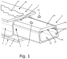
- Fig. 1 shows a stabilizing device 1 according to the invention, which is only partially inserted into a recess 2 of a first FKV component 3 (FKV: fiber-plastic composite) for illustration purposes.
- a second FKV component 4 is attached to the first FKV component 3, but not yet connected to it.
- the first 3 and the second FKV component 4 can also represent larger components with several recesses 2, for example components for aircraft parts 20 such as control surface elements.
- An example of a control surface element is a spoiler 21 (see Fig. 7 ).
- the first FKV component 3 has a reinforcing structure 5 with a hollow profile 7 in the form of an inverted U, which is connected to a first surface element 6.
- the recess 2 is formed by the hollow profile 7.
- Fig. 1 only one recess 2 is shown; however, an FKV component can of course have several recesses 2 and thus have a larger extent than in Fig. 1 shown (see for example Fig. 7 ).
- the reinforcement structure 5 can have a structural pattern that is continued in the same way in the direction of the arrow 41, so that several similar hollow profiles 7 with recesses 2 are present.
- the second FKV component 4 is formed by a second surface element 40 in the illustration shown.
- the second FKV component 4 is attached to the first FKV component 3.
- the second FKV component 4 is to be joined to the first FKV component 3 at a connection point 8 by joining.
- the joining takes place by welding, for example induction welding or ultrasonic welding.
- the connection point 8 can therefore also be referred to as the weld point 8.
- the joining can also be carried out by screwing, gluing or riveting.
- the weld point 8 is indicated by the dashed line and is located on the outside of the recess 2 at the connection point of the first FKV component 3 with the second FKV component 4.
- the weld point 8 is elongated and oriented approximately parallel to the recess 2.
- the stabilizing device 1 is introduced into the recess 2 in the direction of the arrow 9 before welding, preferably essentially completely.
- the stabilizing device 1 has an elongated base body 10, in particular made of metal, which encloses a cavity 11 on the inside.
- the stabilizing device 1 has essentially the same cross-sectional shape as the recess 2. The size of the stabilizing device 1 is adapted to the size of the recess 2.
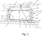
- Fig. 2 shows the stabilizing device 1 in the recess 2 in cross section.
- the base body 10 has a substantially C-shaped cross-sectional shape, which tapers towards the top.
- the cross-sectional shape of the base body 10 has a longitudinal web 44, on whose opposite longitudinal edges 45a, b a first transverse web 46a and a second transverse web 46b protrude.
- the first transverse web 46a forms a first angle ⁇ 1 with the longitudinal web 44.
- the second transverse web 46b forms a second angle ⁇ 2 with the longitudinal web 44.
- the angles ⁇ 1,2 can be 90°, for example.
- At least one of the angles ⁇ 1,2 can also be smaller than 90°, so that the cross-sectional shape of the base body 10 tapers towards the top, as in the embodiment shown. It is also possible that at least one of the angles ⁇ 1,2 (or both) is greater than 90°.
- the transverse webs 46a, b can also have projections 47a, b facing each other at the ends facing away from the longitudinal web.
- One transverse web 46 of the C-profile of the stabilizing device 1 can be made higher than the other transverse web 46 of the C-profile.
- the cross-sectional shape of the base body 10 is preferably essentially the same over the entire length.
- the stabilizing device 1 On the top of the base body 10, the stabilizing device 1 also has an opening 12 between the transverse webs 46, in particular between their projections 47a, b, which connects the cavity 11 with the surroundings.
- the projections 47a, b can taper towards the opening 12. This makes it easier for the bag 14, which will be described in more detail later, to pass through the opening 12.
- the stabilizing device 1 also has a pressing element 13.
- the pressing element 13 consists at least partially of a material that has a higher flexibility, i.e. a lower rigidity, than the material of the base body 10.
- the pressing element 13 has a bag 14 that is located inside the cavity 11 and that consists of a plastic material.
- the pressing element 13 has a thermal insulation element 15 made of ceramic in the form of a thermal insulation plate 16 that is arranged on the outside of the base body 10 above the opening 12 and can rest against the projections 47a, b.
- the thermal insulation element 15 protects the bag 14 from high heat input and also ensures that during welding the heat is not transferred from the welding point 8 to other places, so that the heat for welding is not lost.
- a fluid preferably a Gas, in particular air, causes the bag 14 to expand in the cavity 11 and, via the heat insulating element 15, exerts a compressive force F on a boundary surface 17 delimiting the recess 2 on the inside of the first FKV component 3.
- the shape of the base body 10 remains essentially the same when the pressing element 13 exerts the compressive force F on the boundary surface 17.
- the bag 14 protrudes at least partially through the opening 12.
- the compressive force F is thus transmitted via the opening 12.
- the compressive force F is directed onto the weld point 8 and its immediate surroundings, while the base body 10 hardly deforms and exerts no or only a slight compressive force on the boundary surface 17.
- the fluid is put under a pressure of between 1.0 and 8.0 bar. If the pressure is too high (for example 15 bar), there is a risk that the recess would be deformed by the stabilizing device 1. If the pressure were too low (for example below 1 bar), the pressure force F would be too low and the recess 2 could be deformed during welding.
- the opening 12 can additionally be covered with a film element, a rubber element or a flexible wall element (not shown).
- the welding process can begin in order to connect the first FKV component 3 to the second FKV component 4.
- the compressive force F prevents the recess 2 or the hollow profile 7 from deforming during welding, for example by collapsing.
- the stabilizing device 1 therefore provides a counterpressure that counteracts the pressure exerted during welding, so that the hollow profile 7 cannot collapse.
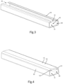
- Fig. 3 shows an oblique view of the elongated base body 10 of the stabilizing device. It can be seen that the cross section of the base body 10 is essentially C-shaped and tapers towards the opening 12. The corners 18 of the The inner surface of the base body 10 is rounded in order to avoid damage to the bag 14 when it is filled.
- the base body 10 can also have an insertion opening 42 on at least one of the two end faces. The bag 14 can be inserted into the cavity 11 and supplied with fluid through one of these insertion openings 42.
- Fig. 4 shows the base body 10 of the stabilizing device 1 together with the heat insulating element 15. It can be seen that the heat insulating element 15 also has an elongated shape and is essentially trapezoidal in cross section, wherein the legs 19 of the trapezoid have a curved or rounded shape.
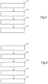
- Fig. 5 represents the sequence of the method according to the invention for joining, in particular welding, FKV components 3, 4.
- step 101 the first 3 and the second FKV component 4 are provided.
- step 102 the stabilizing device 1 is inserted into a recess 2 of the first FKV component 3.
- step 103 the cavity 11 or the bag 14 in the cavity is filled with the fluid so that the pressing element 13 exerts a pressure force F on the connection point 8.
- the first FKV component 3 is connected, in particular welded, to the second FKV component 4.
- the stabilizing device can then be removed from the recess, preferably after the fluid has been at least partially drained from the cavity 11.
- the stabilizing device is reusable.
- the method can also be used in a method for producing an aircraft part 20, for example a control surface element such as a spoiler 21 (see also Fig. 7 ).
- a first surface element 6 is arranged on a table 22.
- the table 22 can have a holding device 23 for fixing FKV components 3, 4.
- an intermediate element 43 with a reinforcing structure 5 is placed on the first surface element 6 and then in step 203, connected to it at a connection point 8a, preferably a Weld point 8a, connected by joining, in particular welded. This results in a first FKV component 3.
- a second surface element 40 which forms a second FKV component 4 is placed on the first FKV component 3. Then, in step 205, the second FKV component 4 is connected to the first FKV component 3 at the point 8 by joining, wherein the method according to Fig. 5 is applied.
- Fig. 7 shows a section of an aircraft part 20 in the form of a spoiler 21 during production.
- two stabilizing devices 1 are at least partially inserted into recesses 2 of a first FKV component 3.
- the first FKV component 3 has a reinforcing structure 5 as an intermediate element 43 and a first surface element 6.
- the reinforcing structure 5 forms hollow profiles 7.
- two essentially vertical connecting webs 48a are connected via an essentially horizontal connecting web 48b.
- This structural pattern continues and forms the reinforcing structure 5.
- a second FKV component 4 in the form of a second surface element 40 is placed on the first FKV component 3 and is to be connected to it by welding at the welding points 8.
- the stabilizing devices 1 stabilize the recesses 2 during welding as explained above.
- the spoiler 21 is manufactured using a tool 24.
- the tool 24 comprises a table 22, preferably with a holding device 23, at least one stabilizing device 1 and a joining device 25, preferably a welding device. This can be attached, for example, to an end effector of a robot (not shown).
Landscapes
- Engineering & Computer Science (AREA)
- Mechanical Engineering (AREA)
- Chemical & Material Sciences (AREA)
- Composite Materials (AREA)
- Physics & Mathematics (AREA)
- Optics & Photonics (AREA)
- Health & Medical Sciences (AREA)
- Electromagnetism (AREA)
- Toxicology (AREA)
- Robotics (AREA)
- Thermal Sciences (AREA)
- Lining Or Joining Of Plastics Or The Like (AREA)
Description
- Die Erfindung betrifft ein Verfahren zum Fügen von Faser-Kunststoff-Verbund-(FKV)-Bauteilen, insbesondere von Flugzeug-Bauteilen, sowie ein Verfahren zur Herstellung eines Flugzeugteils, beispielsweise eines Steuerflächenelements.
- Des Weiteren betrifft die Erfindung eine Stabilisierungsvorrichtung, die, insbesondere während eines Fügeprozesses, zur formerhaltenden und/oder formgebenden Stützung eines Faser-Kunststoff-Verbund-(FKV)-Bauteils in eine Ausnehmung desselben einführbar ist, und folgendes aufweist:
- einen vorzugsweise länglichen Grundkörper mit einem Hohlraum, der mit einem Fluid füllbar ist,
- eine Öffnung, die vorzugsweise am Grundkörper angeordnet ist, und
- Außerdem betrifft die Erfindung ein Werkzeug mit einer solchen Stabilisierungsvorrichtung.
- In der Luftfahrtindustrie werden vielfach Bauteile aus Faser-Kunststoff-Verbund-Material (FKV-Material) eingesetzt, weil sie eine hohe Stabilität und ein geringes Gewicht aufweisen. Bei der Herstellung von Flugzeugteilen, wie beispielsweise eines Steuerflächenelements, werden oftmals mehrere Bauteile aus FKV-Material, im Folgenden auch als FKV-Bauteile bezeichnet, miteinander durch Fügen, wie beispielsweise durch Verschweißen, verbunden. Während des Verschweißens von FKV-Bauteilen kann es jedoch durch die eingebrachte Wärme und den aufgewendeten Druck zu unerwünschten Verformungen der FKV-Bauteile kommen. Dies kann insbesondere bei verstärkenden Strukturen mit Hohlprofilen zu Problemen führen, weil diese bei fehlendem Gegendruck während des Schweißprozesses in sich zusammensacken und so ihre Form und damit ihre verstärkende Wirkung verlieren können.
- Aus dem Stand der Technik ist bekannt, eine aufblasbare oder mit einer Flüssigkeit füllbare Blase aus Silikonkautschuk in Hohlräume von Bauteilen aus FKV-Material einzuführen, um sie dadurch während eines Schweißprozesses zu stärken. Ein solches Verfahren ist aus
US 5,710,414 A bekannt. Nachteilig ist, dass die flexible Blase in alle Richtungen gleichmäßig einen Druck auf das umliegende Bauteil ausübt. Das Bauteil kann daher auch auf unerwünschte Weise verformt werden, weil durch die Blase auch Drucckräfte auf Stellen ausgeübt werden, die keinen Gegendruck durch das Schweißen erfahren. Gelangt Wärme des Schweißprozesses zu diesen Stellen, werden diese aufgeweicht und durch die unter Druck stehende Blase verformt. Weiters kann die Blase aufgrund ihrer Flexibilität nur schwer gezielt in engen Hohlräumen platziert werden. Außerdem kann sie einreißen und an heißen Stellen aufschmelzen und platzen. - Vorrichtungen und Verfahren zum Bearbeiten und Stabilisieren von Bauteilen während der Herstellung sind aus
US 2019/0275747 A1 ,EP 3 711 933 A1 ,US 2017/0036310 A1 ,US 5,366,684 A undUS 2005/0035115 A1 bekannt. - Die
EP 1 070 661 A2 offenbart eine Hilfsvorrichtung, die beim Verbinden von FKV-Bauteilen eingesetzt werden kann. Die Hilfsvorrichtung besitzt mehrere Blasen, die mittels eines Fluids aufgeblasen werden können, um gegen die FKV-Bauteile zu drücken. - Die
WO 2019/094428 A2 betrifft die Herstellung eines Rotorblattes für eine Windturbine. Bei der Herstellung wird eine interne Blase eingesetzt, mit der thermoplastisches Material geformt. - Im Lichte dieser Ausführungen ist es daher Aufgabe der vorliegenden Erfindung, die Nachteile des Standes der Technik zumindest teilweise zu lindern. Bevorzugt ist es Aufgabe der Erfindung, ein Verfahren und eine Stabilisierungsvorrichtung der eingangs erwähnten Art zur Verfügung zu stellen, mit denen eine zielgerichtete und formerhaltende Stabilisierung eines FKV-Bauteils während des Fügens, insbesondere während eines Schweißprozesses, ermöglicht wird. Die Stabilisierungsvorrichtung soll dabei leicht und präzise in Hohlräume einführbar sein.
- Gelöst wird diese Aufgabe zunächst durch ein Verfahren nach Anspruch 1. Erfindungsgemäß weist das Verfahren die folgenden Schritte auf:
- i) Bereitstellen eines ersten und eines zweiten FKV-Bauteils, wobei das erste FKV-Bauteil eine Ausnehmung aufweist;
- ii) Einführen einer Stabilisierungsvorrichtung in die Ausnehmung des ersten FKV-Bauteils, wobei die Stabilisierungsvorrichtung einen vorzugsweise länglichen Grundkörper mit einem Hohlraum, eine Öffnung und ein Anpresselement aufweist, welches Anpresselement zumindest teilweise eine höhere Flexibilität aufweist als der Grundkörper, wobei das Anpresselement einen Sack aufweist, der innerhalb des Hohlraumes angeordnet ist und der zur Erzeugung einer nach außen gerichteten Druckkraft mit einem Fluid füllbar ist, wobei der Sack im gefüllten Zustand dazu eingerichtet ist, zumindest teilweise durch die Öffnung hindurchzuragen, um die Druckkraft auf eine die Ausnehmung begrenzende Begrenzungsfläche des ersten FKV-Bauteils zu erzeugen, wobei das Anpresselement weiters ein Wärmeisolierelement aufweist, welches an der Außenseite des Grundkörpers angeordnet ist, sodass die Druckkraft über das Wärmeisolierelement auf das erste FKV-Bauteil übertragbar ist;
- iii) Füllen des Hohlraums mit dem Fluid, sodass das Anpresselement gegen die die Ausnehmung begrenzende Begrenzungsfläche des ersten FKV-Bauteils gedrückt wird;
- iv) Verbinden des ersten FKV-Bauteils mit dem zweiten FKV-Bauteil an einer Verbindungsstelle durch Fügen, insbesondere durch Verschweißen, wobei mit dem Anpresselement zur Stabilisierung der Form der Ausnehmung der nach außen gerichtete Drucckraft auf die Verbindungsstelle ausgeübt wird.
- Vorteilhafterweise kann mit dem Anpresselement eine Druckkraft zielgerichtet auf die Verbindungsstelle, welche beispielsweise eine Schweißstelle ist, ausgeübt werden und so die Form der Ausnehmung und damit des ersten FKV-Bauteils während des Fügens, insbesondere Verschweißens, erhalten werden. Das Anpresselement wird dabei vom Grundkörper aus betrachtet nach außen gegen die Begrenzungsfläche an der Innenseite des ersten FKV-Bauteils und somit gegen die Verbindungsstelle gedrückt, während die Form des Grundkörpers im Wesentlichen erhalten bleibt. Dies ist darauf zurückzuführen, dass das Anpresselement flexibler ausgestaltet ist als der Grundkörper, d.h. eine geringere Steifigkeit aufweist. Der Grundkörper behält somit im Wesentlichen seine Form bei, während das Anpresselement die Druckkraft auf die Begrenzungsfläche an der Innenseite des ersten FKV-Bauteils ausübt, an deren Außenseite sich die Verbindungsstelle befindet. Die Drucckraft ist dabei (von einem Zentrum der Stabilisierungsvorrichtung aus betrachtet) nach außen gerichtet. Somit übt die Stabilisierungsvorrichtung eine Druckkraft auf das erste FKV-Bauteil aus. Durch die höhere Flexibilität ist das Anpresselement gegenüber dem Grundkörper auslenkbar. Bevorzugt ist das Anpresselement elastisch verformbar. Vorteilhafterweise findet dadurch auch ein Toleranzausgleich bei Bauteilfehlern statt. Die Flexibilität des Anpresselements kann insbesondere dadurch erreicht werden, dass das Anpresselement zumindest teilweise ein Material aufweist, das flexibler, d.h. weniger steif, ist als das Material des Grundkörpers. Es kann auch vorgesehen sein, dass das Anpresselement und der Grundkörper aus dem gleichen Material oder einem ähnlich steifen Material bestehen, das Anpresselement aber ein Gelenk aufweist oder eine dünnere Wandstärke aufweist als der Grundkörper. Durch eine entsprechend dünne Wandstärke kann auch mit an sich harten und steifen Materialien eine hinreichende Flexibilität des Anpresselements erreicht werden. Während das Anpresselement gegen die Begrenzungsfläche am ersten FKV-Bauteil gedrückt wird, ändert sich die Form des Grundkörpers allenfalls nur geringfügig. Im Unterschied dazu wird beim Stand der Technik, wie beispielsweise bei der
US 5,710,414 A , die Druckkraft der Stabilisierungsvorrichtung in alle Richtungen gleichmäßig abgegeben, sodass das Hohlprofil auf unerwünschte Weise verformt werden kann. Das erste und das zweite FKV-Bauteil bestehen zumindest teilweise, vorzugsweise vollständig, aus einem Faser-Kunststoff-Verbund-Material. Als Faser-Kunststoff-Verbund-Material (FKV-Material) wird in dieser Offenbarung ein Werkstoff bezeichnet, der aus Verstärkungsfasern und einer Kunststoffmatrix besteht. Beispiele für FKV-Materialien, aus denen die FKV-Bauteile teilweise oder vollständig bestehen können, sind kohlenstofffaserverstärkter Kunststoff (CFK) oder glasfaserverstärkter Kunststoff (GFK). Das erste FKV-Bauteil und das zweite FKV-Bauteil können beispielsweise Bauteile eines zu erzeugenden Steuerflächenelements für ein Flugzeug, beispielsweise eines Spoilers oder eines Droop-Panels, sein. Die Stabilisierungsvorrichtung wird erfindungsgemäß in eine Ausnehmung des ersten FKV-Bauteils eingeführt. Das erste FKV-Bauteil kann eine Verstärkungsstruktur mit einem oder mehreren Hohlprofilen aufweisen, wobei die Ausnehmung durch das oder eines der Hohlprofile gebildet ist. Die Hohlprofile und damit die Ausnehmung können hinterschnitten oder nicht hinterschnitten sein. Bei der Ausnehmung kann es sich beispielsweise um ein Loch, um einen Hohlraum oder um eine Wölbung des ersten FKV-Bauteils handeln. Da bei Bauteilen für Flugzeuge häufig Verstärkungsstrukturen eingesetzt werden (siehe zum BeispielWO 2016/023056 A1 als Beispiel für eine verstärkende Struktur), ist es günstig, wenn der Grundkörper eine längliche Form aufweist, um ganze Bereiche solcher Strukturen während des Fügens zu stützen und um das Einführen zu erleichtern. Der Grundkörper weist erfindungsgemäß einen Hohlraum auf, der mit einem flüssigen und/oder gasförmigen Fluid füllbar ist. Der Hohlraum liegt vorzugsweise innerhalb des Grundkörpers. Das Fluid kann beispielsweise Luft, Wasser oder Öl sein. Weiters besitzt die Stabilisierungsvorrichtung eine Öffnung, die vorzugsweise am Grundkörper angeordnet ist. Durch die Öffnung kann das Fluid im eingeführten Zustand der Stabilisierungsvorrichtung die Druckkraft auf die Begrenzungsfläche und damit auf die Verbindungsstelle übertragen. Die Öffnung verbindet den Hohlraum mit dem Äußeren der Stabilisierungsvorrichtung und kann in einer Ausführungsform frei, d.h. nicht abgedeckt, sein. Alternativ kann die Öffnung abgedeckt sein, beispielsweise durch eine vorzugsweise flexible Wandstruktur oder durch ein Folienelement. Wichtig ist nur, dass die Druckkraft vom Fluid durch die Öffnung nach außen übertragen werden kann. Durch das Füllen des Hohlraums mit dem Fluid wird das Anpresselement gegen die Begrenzungsfläche an der Innenseite des ersten FKV-Bauteils und damit gegen die Verbindungsstelle gedrückt, da das Anpresselement eine höhere Flexibilität besitzt als der Grundkörper. Die Form des Grundkörpers bleibt somit, wie bereits ausgeführt, im Wesentlichen erhalten, während das Anpresselement sich zumindest teilweise verformt und gegen die Begrenzungsfläche gedrückt wird. Das Material, aus dem das Anpresselement zumindest teilweise besteht, kann beispielsweise ein Folienmaterial oder ein gummiartiges Material sein. Während das Anpresselement gegen die Begrenzungsfläche und damit gegen die Verbindungsstelle drückt, können der erste FKV-Bauteil und der zweite FKV-Bauteil miteinander verschweißt werden. Vorteilhafterweise wird durch die von der Stabilisierungsvorrichtung erzeugte Druckkraft auf die Verbindungsstelle eine Formveränderung der Ausnehmung bzw. des ersten FKV-Bauteils während des Fügens verhindert. Vorzugsweise erfolgt das Fügen des ersten und des zweiten FKV-Bauteils durch Verschweißen. Beispielsweise wird zum Verschweißen des ersten FKV-Bauteils mit dem zweiten FKV-Bauteil ein Induktionsschweißprozess, ein Ultraschallschweißprozess, ein Widerstandsschweißprozess, ein Konduktionsschweißprozess oder ein Laserschweißprozess eingesetzt. Die Verbindungsstelle kann bei Verwendung eines Schweißprozesses zum Fügen auch als Schweißstelle bezeichnet werden. Die von der Stabilisierungsvorrichtung erzeugte Drucckraft wirkt als Gegendruck für den während des Verschweißens aufgebrachten Druck und wirkt dem gleichzeitig erweichenden Material, das durch Temperatureinwirkung erweicht, entgegen. Durch den Gegendruck wird die Form der Ausnehmung und damit des ersten FKV-Bauteils stabilisiert bzw. konsolidiert. In einer bevorzugten Ausführungsform ist die Druckkraft des Anpresselements im Wesentlichen nur in eine Raumrichtung gerichtet. Besonders vorteilhaft ist in den meisten Anwendungsfällen, wenn die Drucckraft im bestimmungsgemäßen Gebrauchszustand der Stabilisierungsvorrichtung, bezogen auf ein Inertialsystem, im Wesentlichen nur nach oben wirkt. Dadurch wird die Ausnehmung des ersten FKV-Bauteils von unten gestützt. Somit kann das zweite FKV-Bauteil von oben mit dem ersten FKV-Bauteil verschweißt werden, ohne die Form des ersten FKV-Bauteils zu verändern. - Das vorliegende Verfahren eignet sich somit zur Stabilisierung eines FKV-Bauteils während eines Fügeprozesses zum Verbinden zweier FKV-Bauteile. Das Fügen kann beispielsweise durch Verschweißen, Verschrauben, Vernieten oder Kleben erfolgen. Vorgesehen ist, dass das Anpresselement einen Sack aufweist, der innerhalb des Hohlraumes angeordnet ist. Der Sack kann zur Erzeugung der Druckkraft mit dem Fluid gefüllt werden, wobei der Sack im gefüllten Zustand zumindest teilweise durch die Öffnung tritt und die Druckkraft auf die Verbindungsstelle erzeugt. Der Sack kann beispielsweise aus einem Gummimaterial oder einem Kunststoffmaterial bestehen. Vorzugsweise erstreckt sich der Sack im Wesentlichen über die gesamte Länge des Hohlraums. In einer besonders bevorzugten Ausführungsform kann es sich bei dem Sack um eine Schlauchfolie handeln, die an einem Ende geschlossen ist und am anderen Ende mit einer Fluidversorgung, insbesondere einer Gasversorgung, verbunden ist. Wenn der Sack mit dem Fluid gefüllt wird (gefüllter Zustand), wird der Sack wegen seiner geringeren Flexibilität im Vergleich zum Grundkörper durch die Öffnung gepresst. Im gefüllten Zustand füllt der Sack vorzugsweise im Wesentlichen den gesamten Hohlraum des Grundkörpers aus. Der Sack ist somit derart flexibel, dass er sich im gefüllten Zustand der Form des Hohlraums im Wesentlichen anpasst.
- Eine besonders leicht auszugestaltende und damit vorteilhafte Variante der Erfindung ergibt sich, wenn als Fluid ein Gas, insbesondere Luft, verwendet wird. Das Gas kann durch einen Kompressor bzw. eine Pumpe in den Hohlraum oder den Sack gefüllt werden. Wie bereits erwähnt, kann das Fluid jedoch auch durch eine Flüssigkeit, beispielsweise ein Öl oder Wasser, gebildet sein.
- Für eine Stabilisierung der Ausnehmung und damit des ersten FKV-Bauteils ist es vorteilhaft, wenn das Fluid zur Erzeugung der Druckkraft unter Druck gesetzt wird und der Druck zwischen 1,0 Bar und 8,0 Bar, vorzugsweise zwischen 1,5 Bar und 5,0 Bar, insbesondere zwischen 2,0 Bar und 3,0 Bar beträgt. Durch einen solchen Druck des Fluids kann den Kräften beim Fügen, insbesondere Schweißen, effektiv entgegengewirkt werden. Bei höheren Drucckräften könnte die Ausnehmung und damit das erste FKV-Bauteil durch die Stabilisierungsvorrichtung unvorteilhafterweise verformt werden. Zu niedrige Druckkräfte (beispielsweise, je nach Bauteil, unter 1 Bar) hätten eine zu geringe Stabilisierungswirkung.
- Insbesondere wenn das Fügen der FKV-Bauteile durch Verschweißen erfolgt, ist es vorteilhaft, wenn das Wärmeisolierelement, insbesondere eine Wärmeisolierplatte, während des Fügens, insbesondere Verschweißens, gegen die Begrenzungsfläche gedrückt wird. Durch das Wärmeisolierelement wird verhindert, dass die eingetragene Wärme zum Verschweißen zu schnell abgeleitet wird. Dadurch kann der Schweißprozess begünstigt werden. Außerdem wird verhindert, dass die eingetragene Wärme im ersten FKV-Bauteil abseits der Schweißstelle verteilt wird, was zur weiteren Stabilisierung des ersten FKV-Bauteils beiträgt. Das Wärmeisolierelement kann an der Außenseite des Grundkörpers beispielsweise lose angeordnet sein. Das Wärmeisolierelement kann alternativ mit dem oben beschriebenen Sack verbunden sein. In einer weiteren Ausführungsform kann das Wärmeisolierelement mit dem Grundkörper verbunden sein, beispielsweise über ein Folienelement oder ein Gummielement. Vorzugsweise besteht das Wärmeisolierelement aus Keramik oder aus einem Polymermaterial, einem FKV-Material oder Faserzement oder aus einer Mischung aus diesen Materialien. In einer besonders bevorzugten Ausführungsform ist das Wärmeisolierelement eine insbesondere plane Wärmeisolierplatte.
- In einer Ausführungsform der Erfindung ist vorgesehen, dass das erste FKV-Bauteil eine Verstärkungsstruktur aufweist und die Ausnehmung zumindest teilweise durch einen Abschnitt der Verstärkungsstruktur gebildet ist. Verstärkungsstrukturen werden bei Flugzeugteilen, insbesondere bei Steuerflächenelementen wie zum Beispiel Spoiler oder Droop-Panels etc., eingesetzt. Bei dieser Ausführungsform wird die Ausnehmung durch ein Hohlprofil der Verstärkungsstruktur gebildet. Eine Verstärkungsstruktur kann beispielsweise im Querschnitt betrachtet einen oder mehrere Verbindungsstege aufweisen. Die Verstärkungsstruktur kann beispielsweise zwei Flächenelemente miteinander verbinden. Der oder die Verbindungsstege können ein Strukturmuster bilden, wobei ein Hohlprofil ausgebildet wird. Das Strukturmuster kann beispielsweise dreiecksförmig, trapezförmig, rechteckig oder wellenförmig sein. Das Strukturmuster kann einzeln vorliegen oder wiederholend fortgesetzt sein. Bei einem beispielhaften Strukturmuster sind beispielsweise zwei im Wesentlichen vertikale Verbindungsstege über einen horizontalen Verbindungssteg miteinander verbunden. Dieses Strukturmuster kann einzeln vorliegen und damit ein einzelnes Hohlprofil ausbilden. Das Strukturmuster kann aber auch wiederholend fortgesetzt werden und mehrere Hohlprofile ausbilden.
- Um allfälligen unbeabsichtigten Verschiebungen der FKV-Bauteile entgegenzuwirken, ist es günstig, wenn zumindest das erste FKV-Bauteil während des Fügens fixiert wird.
- Bei einer Ausführungsform kann vorgesehen sein, dass die Verbindungsstelle vor dem Fügen, während des Fügens und/oder nach dem Fügen durch das Fluid gekühlt oder erwärmt wird, vorzugsweise wobei das Fluid zirkuliert wird. Das Kühlen oder Erwärmen einer Verbindungsstelle ist bei einem Schweißprozess zum Fügen besonders vorteilhaft. Das Fluid kann flüssig oder gasförmig sein. Bei einer besonders bevorzugten Ausführungsform kann vorgesehen sein, dass das Fluid zwischen einer Temperaturregelvorrichtung, insbesondere einer Kühl- und/oder Heizvorrichtung, und dem Hohlraum zirkuliert wird. Dadurch wird Wärmeenergie von dem ersten FKV-Bauteil abgeleitet oder diesem zugeführt. Die Temperaturregelvorrichtung kann das Fluid bei der Zirkulation beispielsweise in einem Temperaturbereich halten.
- Die Erfindung betrifft weiters ein Verfahren zur Herstellung eines Flugzeugteils, beispielsweise eines Steuerflächenelements, insbesondere eines Spoilers, mit den Schritten:
- i) Anordnen eines ersten Flächenelements aus FKV-Material auf einem Tisch;
- ii) Auflegen eines Zwischenelements mit einer Verstärkungsstruktur aus FKV-Material auf das erste Flächenelement;
- iii) Verbinden des Zwischenelements mit dem ersten Flächenelement durch Fügen, insbesondere Verschweißen, an zumindest einer Verbindungsstelle, um einen ersten FKV-Bauteil zu erhalten;
- iv) Auflegen eines zweiten FKV-Bauteils in Form eines zweiten Flächenelements auf das erste FKV-Bauteil;
- v) Verbinden des ersten FKV-Bauteils mit dem zweiten FKV-Bauteil durch Anwenden des Verfahrens zum Fügen von Faser-Kunststoff-Verbund-(FKV)-Bauteilen in einer der oben beschriebenen Ausführungsvarianten.
- Das Steuerflächenelement kann beispielsweise ein Spoiler oder ein Droop-Panel sein. Bei dem ersten Flächenelement kann es sich beispielsweise um eine obere oder untere Außenhaut (engl. "upper skin", "lower skin") einer Störklappe (engl. "Spoiler") handeln. Bei dem zweiten Flächenelement kann es sich korrespondierend zum ersten Flächenelement um die jeweils andere der oberen oder unteren Außenhaut handeln. Bei der Verbindung des ersten Flächenelements mit dem Zwischenelement ist typischerweise noch keine Stabilisierungsvorrichtung notwendig, weil das Zwischenelement auf dem ersten Flächenelement aufliegt und die Verbindungsstellen sich typischerweise in Schritt iii) an keinen Stellen mit darunterliegenden Ausnehmungen befinden, sodass keine Stabilisierung durch die Stabilisierungsvorrichtung notwendig ist. Sollte es notwendig sein, kann aber auch in diesem Schritt bereits eine Stabilisierungsvorrichtung verwendet werden und das oben beschriebene Verfahren zum Fügen angewendet werden. Typischerweise befinden sich die Verbindungsstellen, insbesondere Schweißstellen, in Schritt iii) an Stellen, an denen das Zwischenelement unmittelbar auf dem ersten Flächenelement aufliegt, ohne dass Ausnehmungen wie Hohlräume darunter oder dazwischen liegen. Eine Formveränderung durch Einsacken von Ausnehmungen findet daher typischerweise in Schritt iii) nicht statt. Das erste Flächenelement muss lediglich von unten, beispielsweise durch den Tisch, gestützt werden. Als Tisch kann jede stabile Unterlage bezeichnet werden. In Schritt v) befindet sich jedoch zumindest eine Verbindungsstelle, insbesondere zumindest eine Schweißstelle, an einer Stelle, an der sich darunter eine Ausnehmung befindet, die zumindest teilweise durch die Verstärkungsstruktur des ersten FKV-Bauteils gebildet ist. Um eine Formveränderung der Ausnehmung und damit des ersten FKV-Bauteils zu verhindern, wird die Stabilisierungsvorrichtung in die Ausnehmung eingeführt und das oben beschriebene Verfahren zum Fügen angewandt.
- Nach dem Fügen, insbesondere nach dem Schweißen, des ersten und des zweiten FKV-Bauteils kann die Stabilisierungsvorrichtung aus der Ausnehmung entfernt werden, vorzugsweise nachdem das Fluid zumindest teilweise wieder aus dem Hohlraum abgelassen wurde. Die Stabilisierungsvorrichtung kann erneut verwendet werden.
- Die eingangs erwähnte Aufgabe wird auch durch eine Stabilisierungsvorrichtung nach Anspruch 10 gelöst. Die Stabilisierungsvorrichtung kann insbesondere während eines Fügeprozesses, insbesondere während eines Schweißprozesses, zur formerhaltenden und/oder formgebenden Stützung eines Faser-Kunststoff-Verbund-(FKV)-Bauteils in eine Ausnehmung desselben eingeführt werden. Die erfindungsgemäße Stabilisierungsvorrichtung weist dabei auf:
einen vorzugsweise länglichen Grundkörper mit einem Hohlraum, der mit einem Fluid füllbar ist,
eine Öffnung, die vorzugsweise am Grundkörper angeordnet ist, und
ein bewegliches Anpresselement zur Übertragung einer nach außen gerichteten Druckkraft auf das FKV-Bauteil, wobei das Anpresselement zumindest teilweise eine höhere Flexibilität aufweist als der Grundkörper, wobei die Druckkraft durch Füllen des Hohlraums mit dem Fluid erzeugbar ist, wobei das Anpresselement einen Sack aufweist, der innerhalb des Hohlraumes angeordnet ist und der zur Erzeugung der Druckkraft mit dem Fluid füllbar ist, wobei der Sack dazu eingerichtet ist, im gefüllten Zustand zumindest teilweise durch die Öffnung hindurchzuragen, um die Druckkraft auf eine die Ausnehmung begrenzende Begrenzungsfläche des FKV-Bauteils zu erzeugen, dadurch gekennzeichnet, dass das Anpresselement weiters ein Wärmeisolierelement, aufweist, welches an der Außenseite des Grundkörpers angeordnet ist, sodass die Druckkraft über das Wärmeisolierelement auf das anliegende FKV-Bauteil übertragbar ist. - Hinsichtlich der Vorteile und der Ausgestaltung der Merkmale der Stabiliserungsvorrichtung wird auch auf die Ausführungen in Zusammenhang mit dem oben beschriebenen Verfahren verwiesen. Der Hohlraum im Grundkörper ist mit einem Fluid, beispielsweise einem Gas, insbesondere Luft, oder einer Flüssigkeit, insbesondere Wasser oder Öl, füllbar. Wenn, wie weiter oben und unten beschrieben, das Anpresselement einen Sack aufweist, der in dem Hohlraum angeordnet ist, wird dieser mit dem Fluid gefüllt. Vorzugsweise ist der Grundkörper länglich ausgebildet. Das Anpresselement ist gegenüber dem Grundkörper beweglich. Durch das Füllen des Hohlraumes (oder gegebenenfalls des Sackes im Hohlraum) mit dem Fluid wird das Anpresselement im eingeführten Zustand in der Ausnehmung gegen die Begrenzungsfläche an der Innenseite des ersten FKV-Bauteils gedrückt. Die Form des Grundkörpers bleibt dabei im Wesentlichen erhalten. Die Druckkraft des Fluids wird über die Öffnung auf das FKV-Bauteil übertragen. Durch die höhere Flexibilität des Anpresselements ist dieses gegenüber dem Grundkörper auslenkbar. Bevorzugt ist das Anpresselement elastisch verformbar. Die Flexibilität des Anpresselements kann beispielsweise erreicht werden, indem das Anpresselement zumindest teilweise ein Material aufweist, das flexibler, d.h. weniger steif, ist als das Material des Grundkörpers. Es kann auch vorgesehen sein, dass das Anpresselement und der Grundkörper aus dem gleichen Material oder einem ähnlich steifen Material bestehen, das Anpresselement aber ein Gelenk aufweist oder eine dünnere Wandstärke aufweist als der Grundkörper. Eine geometrische Lösung ist auch möglich, indem zum Beispiel lokale Verstärkungen oder Schwächungen im Material vorgesehen sind. Durch eine entsprechend dünne Wandstärke kann auch mit an sich harten und steifen Materialien eine hinreichende Flexibilität des Anpresselements erreicht werden. Ein Beispiel hierfür ist Aluminium: Ein Grundkörper aus Aluminium ermöglicht bei einer dicken Wandstärke, dass der Grundkörper unter dem Druck des Fluids im Wesentlichen nicht verformt wird. Eine dünne Aluminiumplatte als Anpresselement kann jedoch entsprechend verformt werden.
- Vorgesehen ist, dass das Anpresselement einen Sack aufweist, der innerhalb des Hohlraumes angeordnet ist und der zur Erzeugung der Druckkraft mit dem Fluid füllbar ist, wobei der Sack dazu eingerichtet ist, im gefüllten Zustand zumindest teilweise durch die Öffnung hindurchzuragen, um die Druckkraft auf das Bauteil zu erzeugen. Die Öffnung kann dabei frei sein, sodass der Sack ungehindert durchtreten kann. Die Öffnung kann alternativ aber auch abgedeckt sein, beispielsweise durch ein Folienelement, ein Gummielement oder eine flexible Wandstruktur. Der Sack kann aus einem Kunststoffmaterial oder einem Gummimaterial bestehen. In einer besonders bevorzugten Ausführungsform kann es sich bei dem Sack um eine Schlauchfolie handeln, die an einem Ende geschlossen ist und am anderen Ende mit einer Fluidversorgung, insbesondere einer Gasversorgung, verbunden ist. Im gefüllten Zustand füllt der Sack im Wesentlichen den gesamten Hohlraum aus und passt sich an dessen Form im Wesentlichen an.
- Wenn das Fügen durch Verschweißen der FKV-Bauteile erfolgt, ist es, wie im Zusammenhang mit dem erfindungsgemäßen Verfahren bereits ausgeführt, vorteilhaft, dass das Anpresselement ein Wärmeisolierelement aufweist, welches an der Außenseite des Grundkörpers angeordnet ist, sodass die Druckkraft über das Wärmeisolierelement auf das anliegende Bauteil übertragbar ist. Vorzugsweise ist das Wärmeisolierelement als plane, d.h. ungewölbte, Platte ausgeführt. Das Wärmeisolierelement ist vorzugsweise eine Wärmeisolierplatte.
- In einer bevorzugten Ausführungsform besteht das Wärmeisolierelement aus einem Keramikmaterial, einem Polymermaterial, einem FKV-Material, einem Betonmaterial, einem Zementmaterial, Faserbeton oder einer Mischung aus den genannten Materialien.
- In einer Ausführungsform der Erfindung besteht der Grundkörper aus einem Polymermaterial, einem FKV-Material, einem Metall oder einer Mischung aus den genannten Materialien.
- Für die Stabilisierung von durch Hohlprofile gebildete Ausnehmungen ist es günstig, wenn der Grundkörper im Querschnitt im Wesentlichen U-förmig oder im Wesentlichen C-förmig ist. Die Querschnittsform des Grundkörpers kann einen Längssteg aufweisen, an dessen gegenüberliegenden Längsrändern ein erster Quersteg und ein zweiter Quersteg abstehen. Der erste Quersteg schließt mit dem Längssteg einen ersten Winkel ein. Der zweite Quersteg schließt mit dem Längssteg einen zweiten Winkel ein. Der erste und der zweite Winkel können beispielsweise im Wesentlichen 90° betragen. Der erste und/oder der zweite Winkel kann auch kleiner als 90° sein, sodass sich die Querschnittsform des Grundkörpers zu den freien Enden der Querstege hin verjüngt. Möglich ist auch, dass der erste und/oder der zweite Winkel größer als 90° ist. Die Querstege können auch an den vom Längssteg abgewandten Enden jeweils einander zugewandte Vorsprünge aufweisen. Der eine Quersteg kann höher als der andere Quersteg sein. Vorzugsweise ist die Querschnittsform des Grundkörpers über die gesamte Länge im Wesentlichen gleich. Die Öffnung der Stabilisierungsvorrichtung am Grundkörper kann durch ein offenes Ende des C oder des U gebildet sein. Falls Querstege mit Vorsprüngen vorgesehen sind, kann die Öffnung zwischen den Vorsprüngen ausgebildet sein. Die Vorsprünge können auch so ausgeführt sein, dass sie sich im Querschnitt zur Öffnung hin jeweils verjüngen. Dadurch kann die Druckkraft effektiver auf die Verbindungsstelle übertragen werden, insbesondere, wenn ein Sack vorgesehen ist.
- Da sich verstärkende Strukturen in Flugzeugteilen wie Spoiler oftmals zu einer Seite hin verjüngen, ist es günstig, wenn sich auch die Querschnittsform des Grundkörpers zur Öffnung hin verjüngt. Wenn der Querschnitt im Wesentlichen C- oder U-förmig ist und die Öffnung durch das offene Ende des C oder U gebildet ist, verjüngt sich die Querschnittsform des Grundkörpers zum offenen Ende des C oder U hin.
- Die Stabilisierungsvorrichtung kann einen Bestandteil eines Werkzeugs zum Fügen von Faser-Kunststoff-Verbund-(FKV)-Bauteilen bilden. Ein solches Werkzeug kann aufweisen:
- einen Tisch, vorzugsweise mit einer Haltevorrichtung zum Fixieren eines FKV-Bauteils;
- eine Fügevorrichtung, insbesondere eine Schweißvorrichtung;
- eine Stabilisierungsvorrichtung in einer der oben beschriebenen Ausführungsvarianten.
- Mit der Fügevorrichtung können FKV-Materialien miteinander verbunden, insbesondere verschweißt, werden. Insbesondere kann die Schweißvorrichtung als Induktionsschweißvorrichtung ausgebildet sein. Alternativ kann die Schweißvorrichtung beispielsweise eine Ultraschallschweißvorrichtung, eine Widerstandsschweißvorrichtung, eine Konduktionsschweißvorrichtung oder eine Laserschweißvorrichtung sein. Die Fügevorrichtung kann an einem Roboter, insbesondere an einem Roboterarm, angeordnet sein.
- Diese Offenbarung bezieht sich auch auf die Kombination aus dem Werkzeug wie oben beschrieben mit dem ersten und dem zweiten FKV-Bauteil wie oben beschrieben.
- Im Folgenden wird die Erfindung an Hand von Figuren näher erläutert, auf die sie jedoch nicht beschränkt sein soll.
- Es zeigen:
-
Fig. 1 eine erfindungsgemäße Stabilisierungsvorrichtung, die teilweise in eine Ausnehmung eines ersten FKV-Bauteils eingeführt ist; -
Fig. 2 eine erfindungsgemäße Stabilisierungsvorrichtung in einer Ausnehmung eines ersten FKV-Bauteils im Querschnitt; -
Fig. 3 einen Grundkörper einer erfindungsgemäßen Stabilisierungsvorrichtung; -
Fig. 4 eine erfindungsgemäße Stabilisierungsvorrichtung mit einem Wärmeisolierelement; -
Fig. 5 einen Ablauf des erfindungsgemäßen Verfahrens zum Fügen von zwei FKV-Bauteilen; -
Fig. 6 einen Ablauf des erfindungsgemäßen Verfahrens zur Herstellung eines Flugzeugteils; und -
Fig. 7 einen Ausschnitt eines Flugzeugteils bei der Herstellung. -
Fig. 1 zeigt eine erfindungsgemäße Stabilisierungsvorrichtung 1, die zur Veranschaulichung nur teilweise in eine Ausnehmung 2 eines ersten FKV-Bauteils 3 (FKV: Faser-Kunststoff-Verbund) eingeführt ist. Ein zweites FKV-Bauteil 4 ist an das erste FKV-Bauteil 3 angefügt, aber noch nicht mit diesem verbunden. Selbstverständlich können das erste 3 und das zweite FKV-Bauteil 4 auch größere Bauteile mit mehreren Ausnehmungen 2 darstellen, beispielsweise Bauteile für Flugzeugteile 20 wie etwa Steuerflächenelemente. Ein Beispiel für ein Steuerflächenelement ist ein Spoiler 21 (sieheFig. 7 ). - Das erste FKV-Bauteil 3 besitzt in der gezeigten Darstellung eine Verstärkungsstruktur 5 mit einem Hohlprofil 7 in Form eines umgedrehten U, die mit einem ersten Flächenelement 6 verbunden ist. Die Ausnehmung 2 wird durch das Hohlprofil 7 gebildet. In
Fig. 1 ist nur eine einzige Ausnehmung 2 dargestellt; ein FKV-Bauteil kann jedoch selbstverständlich mehrere Ausnehmungen 2 und damit eine größere Ausdehnung aufweisen als inFig. 1 dargestellt (siehe zum BeispielFig. 7 ). Beispielsweise kann die Verstärkungsstruktur 5 ein Strukturmuster aufweisen, das in Richtung des Pfeils 41 gleichartig fortgesetzt ist, sodass mehrere gleichartige Hohlprofile 7 mit Ausnehmungen 2 vorliegen. Das zweite FKV-Bauteil 4 ist in der gezeigten Darstellung durch ein zweites Flächenelement 40 gebildet. - In
Fig. 1 ist das zweite FKV-Bauteil 4 an das erste FKV-Bauteil 3 angefügt. Das zweite FKV-Bauteil 4 soll mit dem ersten FKV-Bauteil 3 an einer Verbindungsstelle 8 durch Fügen verbunden werden. Bei den im Folgenden beschriebenen Ausführungsformen der Erfindung erfolgt das Fügen durch Verschweißen, beispielsweise Induktionsschweißen oder Ultraschallschweißen. Die Verbindungsstelle 8 kann daher auch als Schweißstelle 8 bezeichnet werden. Das Fügen kann prinzipiell aber auch durch Verschrauben, Kleben oder Vernieten erfolgen. Die Schweißstelle 8 ist durch die gestrichelte Linie angedeutet und befindet sich an der Außenseite der Ausnehmung 2 an der Verbindungsstelle des ersten FKV-Bauteils 3 mit dem zweiten FKV-Bauteil 4. Die Schweißstelle 8 ist länglich ausgebildet und in etwa parallel zur Ausnehmung 2 orientiert. - Um zu verhindern, dass während des Verschweißens durch die eingebrachte Wärme und den aufgewendeten Druck das Hohlprofil 7 und damit auch die Ausnehmung 2 verformt wird, wird erfindungsgemäß vor dem Verschweißen die Stabilisierungsvorrichtung 1 in die Ausnehmung 2 in Pfeilrichtung 9 eingeführt, und zwar vorzugsweise im Wesentlichen vollständig. Die Stabilisierungsvorrichtung 1 weist in der gezeigten Ausführungsform einen länglichen Grundkörper 10 insbesondere aus Metall auf, der im Inneren einen Hohlraum 11 einschließt. In der gezeigten Ausführungsform besitzt die Stabilisierungsvorrichtung 1 im Wesentlichen die gleiche Querschnittsform wie die Ausnehmung 2. Die Größe der Stabilisierungsvorrichtung 1 ist an die Größe der Ausnehmung 2 angepasst.
-
Fig. 2 zeigt die Stabilisierungsvorrichtung 1 in der Ausnehmung 2 im Querschnitt. Wie inFig. 2 ersichtlich, besitzt der Grundkörper 10 eine im Wesentlichen C-förmige Querschnittsform, die sich nach oben hin verjüngt. Die Querschnittsform des Grundkörpers 10 besitzt in der gezeigten Ausführungsform einen Längssteg 44, an dessen gegenüberliegenden Längsrändern 45a, b ein erster Quersteg 46a und ein zweiter Quersteg 46b abstehen. Der erste Quersteg 46a schließt mit dem Längssteg 44 einen ersten Winkel α1 ein. Der zweite Quersteg 46b schließt mit dem Längssteg 44 einen zweiten Winkel α2 ein. Die Winkel α1,2 können beispielsweise 90° betragen. Zumindest einer der Winkel α1,2 (auch beide) kann auch kleiner als 90° sein, sodass sich die Querschnittsform des Grundkörpers 10, wie in der gezeigten Ausführungsform, nach oben hin verjüngt. Möglich ist auch, dass zumindest einer der Winkel α1,2 (auch beide) größer als 90° ist. Die Querstege 46a, b können, wie gezeigt, auch an den vom Längssteg abgewandten Enden jeweils einander zugewandte Vorsprünge 47a, b aufweisen. Der eine Quersteg 46 des C-Profils der Stabilisierungsvorrichtung 1 kann höher als der andere Quersteg 46 des C-Profils ausgeführt sein. Vorzugsweise ist die Querschnittsform des Grundkörpers 10 über die gesamte Länge im Wesentlichen gleich. An der Oberseite des Grundkörpers 10 weist die Stabilisierungsvorrichtung 1 zudem eine Öffnung 12 zwischen den Querstegen 46, insbesondere zwischen deren Vorsprünge 47a, b, auf, die den Hohlraum 11 mit der Umgebung verbindet. Die Vorsprünge 47a, b können sich zur Öffnung 12 hin verjüngen. Dadurch kann der noch näher zu beschreibende Sack 14 leichter durch die Öffnung 12 treten. Die Stabilisierungsvorrichtung 1 weist des Weiteren ein Anpresselement 13 auf. Das Anpresselement 13 besteht in der gezeigten Ausführungsform zumindest teilweise aus einem Material, das eine höhere Flexibilität, d.h. eine geringere Steifigkeit, als das Material des Grundkörpers 10 aufweist. In der gezeigten Ausführungsform weist das Anpresselement 13 einen Sack 14 auf, der sich im Inneren des Hohlraums 11 befindet und der aus einem Kunststoffmaterial besteht. Weiters besitzt das Anpresselement 13 ein Wärmeisolierelement 15 aus Keramik in Form einer Wärmeisolierplatte 16, die an der Außenseite des Grundkörpers 10 über der Öffnung 12 angeordnet ist und an den Vorsprüngen 47a, b anliegen kann. Das Wärmeisolierelement 15 schützt den Sack 14 vor hohem Wärmeeintrag und sorgt auch dafür, dass während des Verschweißens die Wärme nicht von der Schweißstelle 8 an andere Stellen übertragen wird, sodass die Wärme zum Verschweißen nicht verloren geht. Durch Füllen des Sackes 14 mit einem Fluid, vorzugsweise einem Gas, insbesondere Luft, dehnt sich der Sack 14 im Hohlraum 11 aus und übt über das Wärmeisolierelement 15 eine Druckkraft F auf eine die Ausnehmung 2 begrenzende Begrenzungsfläche 17 an der Innenseite des ersten FKV-Bauteils 3 aus. Aufgrund der höheren Steifigkeit und damit geringeren Flexibilität des Grundkörpers 10 im Vergleich zu dem Sack 14 bleibt die Form des Grundkörpers 10 im Wesentlichen gleich, wenn das Anpresselement 13 die Druckkraft F auf die Begrenzungsfläche 17 ausübt. Im gefüllten Zustand ragt der Sack 14 dabei zumindest teilweise durch die Öffnung 12. Die Druckkraft F wird somit über die Öffnung 12 übertragen. Dadurch wird die Druckkraft F auf die Schweißstelle 8 und deren unmittelbare Umgebung gelenkt, während der Grundkörper 10 sich kaum verformt und keine oder nur eine geringe Drucckraft auf die Begrenzungsfläche 17 ausübt. Um die Druckkraft F zu erzeugen, wird das Fluid unter einen Druck gesetzt, der zwischen 1,0 und 8,0 Bar beträgt. Bei einem zu hohen Druck (beispielsweise 15 Bar) bestünde das Risiko, dass die Ausnehmung durch die Stabilisierungsvorrichtung 1 verformt würde. Wäre der Druck zu niedrig (beispielsweise unter 1 Bar), wäre die Drucckraft F zu niedrig und die Ausnehmung 2 könnte beim Verschweißen verformt werden. Die Öffnung 12 kann zusätzlich noch mit einem Folienelement, einem Gummielement oder einem flexiblen Wandelement (nicht gezeigt) abgedeckt sein. - Wenn das Anpresselement 13 eine Druckkraft F auf die Begrenzungsfläche 17 der Ausnehmung 2 ausübt, kann mit dem Schweißprozess begonnen werden, um das erste FKV-Bauteil 3 mit dem zweiten FKV-Bauteil 4 zu verbinden. Durch die Druckkraft F wird verhindert, dass sich die Ausnehmung 2 bzw. das Hohlprofil 7 während des Verschweißens, beispielsweise durch Zusammensacken, verformt. Die Stabilisierungsvorrichtung 1 stellt also einen Gegendruck zur Verfügung, der dem ausgeübten Druck während des Schweißens entgegenwirkt, sodass das Hohlprofil 7 nicht zusammensacken kann.
-
Fig. 3 zeigt eine Schrägansicht auf den länglichen Grundkörper 10 der Stabilisierungsvorrichtung. Es ist erkennbar, dass der Querschnitt des Grundkörpers 10 im Wesentlichen C-förmig ist und sich in Richtung zur Öffnung 12 hin verjüngt. Die Ecken 18 der Innenfläche des Grundkörpers 10 sind abgerundet, um Beschädigungen des Sackes 14 in dessen gefüllten Zustand zu vermeiden. Der Grundkörper 10 kann weiters an zumindest einer der beiden Stirnseiten eine Einführöffnung 42 aufweisen. Durch eine dieser Einführöffnungen 42 kann der Sack 14 in den Hohlraum 11 eingeführt und mit Fluid versorgt werden. -
Fig. 4 zeigt den Grundkörper 10 der Stabilisierungsvorrichtung 1 gemeinsam mit dem Wärmeisolierelement 15. Es ist erkennbar, dass das Wärmeisolierelement 15 ebenfalls eine längliche Form aufweist und im Querschnitt im Wesentlichen trapezförmig ist, wobei die Schenkel 19 des Trapezes eine gewölbte oder abgerundete Form aufweisen. -
Fig. 5 stellt den Ablauf des erfindungsgemäßen Verfahrens zum Fügen, insbesondere Verschweißen, von FKV-Bauteilen 3, 4 dar. In Schritt 101 werden der erste 3 und der zweite FKV-Bauteil 4 bereitgestellt. In Schritt 102 wird die Stabilisierungsvorrichtung 1 in eine Ausnehmung 2 des ersten FKV-Bauteils 3 eingefügt. In Schritt 103 wird der Hohlraum 11 bzw. der Sack 14 in dem Hohlraum mit dem Fluid gefüllt, sodass das Anpresselement 13 eine Druckkraft F auf die Verbindungsstelle 8 ausübt. In Schritt 104 wird das erste FKV-Bauteil 3 mit dem zweiten FKV-Bauteil 4 verbunden, insbesondere verschweißt. Anschließend kann die Stabilisierungsvorrichtung aus der Ausnehmung entfernt werden, vorzugsweise, nachdem das Fluid wieder zumindest teilweise aus dem Hohlraum 11 abgelassen wurde. Die Stabilisierungsvorrichtung ist wiederverwendbar. - Das Verfahren kann auch bei einem Verfahren zur Herstellung eines Flugzeugteils 20, beispielsweise eines Steuerflächenelements wie etwa ein Spoiler 21, verwendet werden (vgl. auch
Fig. 7 ). InFig. 6 sind hierzu die einzelnen Schritte dargestellt. In Schritt 201 wird ein erstes Flächenelement 6 auf einem Tisch 22 angeordnet. Der Tisch 22 kann eine Haltevorrichtung 23 zum Fixieren von FKV-Bauteilen 3, 4 aufweisen. In Schritt 202 wird ein Zwischenelement 43 mit einer Verstärkungsstruktur 5 auf das erste Flächenelement 6 aufgelegt und mit diesem anschließend in Schritt 203 an einer Verbindungsstelle 8a, vorzugsweise einer Schweißstelle 8a, durch Fügen verbunden, insbesondere verschweißt. Dadurch wird ein erstes FKV-Bauteil 3 erhalten. In einem Schritt 204 wird ein zweites Flächenelement 40, das einen zweiten FKV-Bauteil 4 bildet, auf das erste FKV-Bauteil 3 gelegt. Anschließend wird in Schritt 205 das zweite FKV-Bauteil 4 mit dem ersten FKV-Bauteil 3 an der Stelle 8 durch Fügen verbunden, wobei das Verfahren nachFig. 5 angewendet wird. -
Fig. 7 zeigt einen Ausschnitt eines Flugzeugteils 20 in Form eines Spoilers 21 bei der Herstellung. Hierbei sind zwei Stabilisierungsvorrichtungen 1 zumindest teilweise in Ausnehmungen 2 eines ersten FKV-Bauteils 3 eingeführt. Das erste FKV-Bauteil 3 weist eine Verstärkungsstruktur 5 als Zwischenelement 43 und ein erstes Flächenelement 6 auf. Die Verstärkungsstruktur 5 bildet Hohlprofile 7 aus. Bei der dargestellten Verstärkungsstruktur 5 sind jeweils zwei im Wesentlichen vertikale Verbindungsstege 48a über einen im Wesentlichen horizontalen Verbindungssteg 48b verbunden. Dieses Strukturmuster setzt sich fort und bildet die Verstärkungsstruktur 5. Ein zweites FKV-Bauteil 4 in Form eines zweiten Flächenelements 40 ist auf das erste FKV-Bauteil 3 aufgelegt und soll mit diesem durch Verschweißen an den Schweißstellen 8 verbunden werden. Die Stabilisierungsvorrichtungen 1 stabilisieren die Ausnehmungen 2 während des Verschweißens wie oben ausgeführt. Der Spoiler 21 wird mittels eines Werkzeugs 24 hergestellt. Das Werkzeug 24 umfasst einen Tisch 22, vorzugsweise mit einer Haltevorrichtung 23, zumindest eine Stabilisierungsvorrichtung 1 und eine Fügevorrichtung 25, vorzugsweise eine Schweißvorrichtung. Diese kann beispielsweise an einem Endeffektor eines Roboters angebracht sein (nicht gezeigt).
Claims (15)
- Verfahren zum Fügen von Faser-Kunststoff-Verbund-(FKV)-Bauteilen (3, 4), insbesondere Flugzeug-FKV-Bauteilen, mit den folgenden Schritten:i) Bereitstellen eines ersten (3) und eines zweiten FKV-Bauteils (4), wobei das erste FKV-Bauteil (3) eine Ausnehmung (2) aufweist;ii) Einführen einer Stabilisierungsvorrichtung (1) in die Ausnehmung (2) des ersten FKV-Bauteils (3), wobei die Stabilisierungsvorrichtung (1) einen vorzugsweise länglichen Grundkörper (10) mit einem Hohlraum (11), eine Öffnung (12) und ein Anpresselement (13) aufweist, welches Anpresselement (13) zumindest teilweise eine höhere Flexibilität aufweist als der Grundkörper (10), wobei das Anpresselement (13) einen Sack (14) aufweist, der innerhalb des Hohlraumes (11) angeordnet ist und der zur Erzeugung einer nach außen gerichteten Druckkraft (F) mit einem Fluid füllbar ist, wobei der Sack (14) im gefüllten Zustand dazu eingerichtet ist, zumindest teilweise durch die Öffnung (12) hindurchzuragen, um die Druckkraft (F) auf eine die Ausnehmung (2) begrenzende Begrenzungsfläche (17) des ersten FKV-Bauteils (3) zu erzeugen, wobei das Anpresselement (13) weiters ein Wärmeisolierelement (15) aufweist, welches an der Außenseite des Grundkörpers (10) angeordnet ist, sodass die Drucckraft (F) über das Wärmeisolierelement (15) auf das erste FKV-Bauteil (3) übertragbar ist;iii) Füllen des Hohlraums (11) mit dem Fluid, sodass das Anpresselement (13) gegen die die Ausnehmung (2) begrenzende Begrenzungsfläche (17) des ersten FKV-Bauteils (3) gedrückt wird;iv) Verbinden des ersten FKV-Bauteils (3) mit dem zweiten FKV-Bauteil (4) an einer Verbindungsstelle (8) durch Fügen, insbesondere durch Verschweißen, wobei mit dem Anpresselement (13) zur Stabilisierung der Form der Ausnehmung (2) der nach außen gerichtete Druckkraft (F) auf die Verbindungsstelle (8) ausgeübt wird.
- Verfahren nach Anspruch 1, wobei der Sack (14) zur Erzeugung der Druckkraft (F) mit dem Fluid gefüllt wird, wobei der Sack (14) im gefüllten Zustand zumindest teilweise durch die Öffnung (12) tritt und die Druckkraft (F) auf die Verbindungsstelle (8) erzeugt.
- Verfahren nach Anspruch 1 oder 2, wobei als Fluid ein Gas, insbesondere Luft, verwendet wird.
- Verfahren nach einem der Ansprüche 1 bis 3, wobei das Fluid zur Erzeugung der Druckkraft (F) unter Druck gesetzt wird und der Druck zwischen 1,0 Bar und 8,0 Bar, vorzugsweise zwischen 1,5 Bar und 5,0 Bar, insbesondere zwischen 2,0 Bar und 3,0 Bar beträgt.
- Verfahren nach einem der Ansprüche 1 bis 4, wobei das Wärmeisolierelement (15), insbesondere eine Wärmeisolierplatte (16), während des Fügens gegen die Begrenzungsfläche (17) des ersten FKV-Bauteils (3) gedrückt wird.
- Verfahren nach einem der Ansprüche 1 bis 5, wobei das erste FKV-Bauteil (3) eine Verstärkungsstruktur (5) aufweist und die Ausnehmung (2) zumindest teilweise durch einen Abschnitt der Verstärkungsstruktur (5) gebildet ist.
- Verfahren nach einem der Ansprüche 1 bis 6, wobei zumindest das erste FKV-Bauteil (3) während des Fügens fixiert wird.
- Verfahren nach einem der Ansprüche 1 bis 7, wobei die Verbindungsstelle (8) vor dem Fügen, während des Fügens und/oder nach dem Fügen durch das Fluid gekühlt oder erwärmt wird, vorzugsweise wobei das Fluid zirkuliert wird.
- Verfahren zur Herstellung eines Flugzeugteils (20), beispielsweise eines Steuerflächenelements, insbesondere eines Spoilers (21), mit den Schritten:i) Anordnen eines ersten Flächenelements (6) aus FKV-Material auf einem Tisch (22);ii) Auflegen eines Zwischenelements (43) mit einer Verstärkungsstruktur (5) aus FKV-Material auf das erste Flächenelement (6) ;iii) Verbinden des Zwischenelements (43) mit dem ersten Flächenelement (6) durch Fügen, insbesondere Verschweißen, an zumindest einer Verbindungsstelle (8a), um einen ersten FKV-Bauteil (3) zu erhalten;iv) Auflegen eines zweiten FKV-Bauteils (4) in Form eines zweiten Flächenelements (40) auf das erste FKV-Bauteil (3);v) Verbinden des ersten FKV-Bauteils (3) mit dem zweiten FKV-Bauteil (4) durch Anwenden des Verfahrens nach einem der Ansprüche 1 bis 8.
- Stabilisierungsvorrichtung (1), die, insbesondere während eines Fügeprozesses, zur formerhaltenden und/oder formgebenden Stützung eines Faser-Kunststoff-Verbund-(FKV)-Bauteils (3) in eine Ausnehmung (2) desselben einführbar ist, aufweisend:einen vorzugsweise länglichen Grundkörper (10) mit einem Hohlraum (11), der mit einem Fluid füllbar ist,eine Öffnung (12), die vorzugsweise am Grundkörper (10) angeordnet ist, undein bewegliches Anpresselement (13) zur Übertragung einer nach außen gerichteten Druckkraft (F) auf das FKV-Bauteil (3), wobei das Anpresselement (13) zumindest teilweise eine höhere Flexibilität aufweist als der Grundkörper (10), wobei die Druckkraft (F) durch Füllen des Hohlraums (11) mit dem Fluid erzeugbar ist, wobei das Anpresselement (13) einen Sack (14) aufweist, der innerhalb des Hohlraumes (11) angeordnet ist und der zur Erzeugung der Druckkraft (F) mit dem Fluid füllbar ist, wobei der Sack (14) dazu eingerichtet ist, im gefüllten Zustand zumindest teilweise durch die Öffnung (12) hindurchzuragen, um die Druckkraft (F) auf eine die Ausnehmung (2) begrenzende Begrenzungsfläche (17) des FKV-Bauteils (3) zu erzeugen, dadurch gekennzeichnet, dass das Anpresselement (13) weiters ein Wärmeisolierelement (15), aufweist, welches an der Außenseite des Grundkörpers (10) angeordnet ist, sodass die Druckkraft (F) über das Wärmeisolierelement (15) auf das anliegende FKV-Bauteil (3) übertragbar ist.
- Stabilisierungsvorrichtung (1) nach Anspruch 10, dadurch gekennzeichnet, dass das Wärmeisolierelement (15) eine Wärmeisolierplatte (16) ist und das Wärmeisolierelement (15) vorzugsweise aus einem Keramikmaterial, einem Polymermaterial, einem FKV-Material, einem Betonmaterial, einem Zementmaterial, Faserbeton oder einer Mischung aus den genannten Materialien besteht.
- Stabilisierungsvorrichtung (1) nach Anspruch 10 oder 11, dadurch gekennzeichnet, dass der Grundkörper (10) aus einem Polymermaterial, einem FKV-Material, einem Metall oder einer Mischung aus den genannten Materialien besteht.
- Stabilisierungsvorrichtung (1) nach einem der Ansprüche 10 bis 12, dadurch gekennzeichnet, dass der Grundkörper (10) im Querschnitt im Wesentlichen U-förmig oder im Wesentlichen C-förmig ist.
- Stabilisierungsvorrichtung (1) nach einem der Ansprüche 10 bis 13, dadurch gekennzeichnet, dass sich die Querschnittsform des Grundkörpers (10) zur Öffnung (12) hin verjüngt.
- Werkzeug (24) zum Fügen von Faser-Kunststoff-Verbund-(FKV)-Bauteilen (3, 4), aufweisend:- einen Tisch (22), vorzugsweise mit einer Haltevorrichtung zum Fixieren eines FKV-Bauteils (3, 4);- eine Fügevorrichtung (25), insbesondere eine Schweißvorrichtung;- eine Stabilisierungsvorrichtung (1) nach einem der Ansprüche 10 bis 14.
Priority Applications (1)
| Application Number | Priority Date | Filing Date | Title |
|---|---|---|---|
| HRP20250228TT HRP20250228T1 (hr) | 2021-05-27 | 2022-05-27 | Postupak za povezivanje komponenata kompozita vlakana i plastičnog materijala i uređaj za stabilizaciju |
Applications Claiming Priority (2)
| Application Number | Priority Date | Filing Date | Title |
|---|---|---|---|
| ATA50423/2021A AT524687B1 (de) | 2021-05-27 | 2021-05-27 | Verfahren zum Verschweißen von Faser-Kunststoff-Verbund-(FKV)-Bauteilen und Stabilisierungsvorrichtung |
| PCT/AT2022/060182 WO2022246490A1 (de) | 2021-05-27 | 2022-05-27 | Verfahren zum fügen von faser-kunststoff-verbund-bauteilen und stabilisierungsvorrichtung |
Publications (2)
| Publication Number | Publication Date |
|---|---|
| EP4347225A1 EP4347225A1 (de) | 2024-04-10 |
| EP4347225B1 true EP4347225B1 (de) | 2024-12-18 |
Family
ID=81928159
Family Applications (1)
| Application Number | Title | Priority Date | Filing Date |
|---|---|---|---|
| EP22727246.5A Active EP4347225B1 (de) | 2021-05-27 | 2022-05-27 | Verfahren zum fügen von faser-kunststoff-verbund-bauteilen und stabilisierungsvorrichtung |
Country Status (9)
| Country | Link |
|---|---|
| US (1) | US12397513B2 (de) |
| EP (1) | EP4347225B1 (de) |
| CN (1) | CN117615898A (de) |
| AT (1) | AT524687B1 (de) |
| BR (1) | BR112023024468A2 (de) |
| CA (1) | CA3221434A1 (de) |
| ES (1) | ES3027837T3 (de) |
| HR (1) | HRP20250228T1 (de) |
| WO (1) | WO2022246490A1 (de) |
Family Cites Families (11)
| Publication number | Priority date | Publication date | Assignee | Title |
|---|---|---|---|---|
| US5710414A (en) | 1991-04-05 | 1998-01-20 | The Boeing Company | Internal tooling for induction heating |
| US5366684A (en) * | 1992-12-31 | 1994-11-22 | Grumman Aerospace Corporation | Molding composite method using an inflatable bladder pressurized in an autoclave |
| US6513757B1 (en) | 1999-07-19 | 2003-02-04 | Fuji Jukogyo Kabushiki Kaisha | Wing of composite material and method of fabricating the same |
| US6979807B2 (en) * | 2003-08-13 | 2005-12-27 | The Boeing Company | Forming apparatus and method |
| US9090022B1 (en) * | 2009-09-17 | 2015-07-28 | Flexible Steel Lacing Company | Belt splicing apparatus for conveyor belts |
| AT516211A1 (de) | 2014-08-11 | 2016-03-15 | Facc Ag | Steuerflächenelement |
| US9993946B2 (en) * | 2015-08-05 | 2018-06-12 | The Boeing Company | Method and apparatus for forming tooling and associated materials therefrom |
| US10961982B2 (en) | 2017-11-07 | 2021-03-30 | General Electric Company | Method of joining blade sections using thermoplastics |
| US11046020B2 (en) * | 2018-03-09 | 2021-06-29 | Stelia Aerospace | System and method for producing structural thermoplastic parts |
| US11279092B2 (en) * | 2019-03-19 | 2022-03-22 | The Boeing Company | Method and system for co-consolidation of thermoplastic composite material parts |
| DE102019111226A1 (de) | 2019-04-30 | 2020-11-05 | Airbus Operations Gmbh | Vorrichtung, Anordnung und Verfahren zum Strahlschweißen mit Kühlung |
-
2021
- 2021-05-27 AT ATA50423/2021A patent/AT524687B1/de active
-
2022
- 2022-05-27 WO PCT/AT2022/060182 patent/WO2022246490A1/de not_active Ceased
- 2022-05-27 ES ES22727246T patent/ES3027837T3/es active Active
- 2022-05-27 BR BR112023024468A patent/BR112023024468A2/pt unknown
- 2022-05-27 HR HRP20250228TT patent/HRP20250228T1/hr unknown
- 2022-05-27 US US18/564,592 patent/US12397513B2/en active Active
- 2022-05-27 CA CA3221434A patent/CA3221434A1/en active Pending
- 2022-05-27 CN CN202280045599.3A patent/CN117615898A/zh active Pending
- 2022-05-27 EP EP22727246.5A patent/EP4347225B1/de active Active
Also Published As
| Publication number | Publication date |
|---|---|
| ES3027837T3 (en) | 2025-06-17 |
| CA3221434A1 (en) | 2022-12-01 |
| BR112023024468A2 (pt) | 2024-02-06 |
| US12397513B2 (en) | 2025-08-26 |
| WO2022246490A1 (de) | 2022-12-01 |
| AT524687A4 (de) | 2022-08-15 |
| EP4347225A1 (de) | 2024-04-10 |
| US20240239058A1 (en) | 2024-07-18 |
| HRP20250228T1 (hr) | 2025-04-11 |
| AT524687B1 (de) | 2022-08-15 |
| CN117615898A (zh) | 2024-02-27 |
Similar Documents
| Publication | Publication Date | Title |
|---|---|---|
| DE60226336T2 (de) | Verfahren zum innenhochdruckumformen von gegenständen und damit hergestellter gegenstand | |
| DE69636148T2 (de) | Sandwichstrukturen mit mehreren Blechen und einem integrierten Hardpoint | |
| DE102008010197B4 (de) | Verfahren zum Verbinden von zwei Rumpfsektionen unter Schaffung eines Querstoßes sowie Querstoßverbindung | |
| DE68907299T2 (de) | Gewölbte Schichtstruktur und Verfahren zu ihrer Herstellung durch superplastische Verformung und Diffusionsschweissung. | |
| EP1439121B1 (de) | Leichtbau-Strukturbauteil insbesondere für Flugzeuge und Verfahren zu seiner Herstellung | |
| DE102008020347B4 (de) | Vorrichtung zur Herstellung eines Bauteils und Verfahren | |
| DE3113791C2 (de) | ||
| DE69731956T2 (de) | Superplastisches formen eines bauelementes | |
| EP2724036B1 (de) | Bauteil zur aufnahme und/oder übertragung von mechanischen kräften und/oder momenten, ein verfahren zu dessen herstellung und dessen verwendung | |
| DE102008062020B4 (de) | Fahrradkurbel und Verfahren zu ihrer Herstellung | |
| EP2316637A1 (de) | Verfahren zur Herstellung eines integralen Faserverbundbauteils | |
| DE102016210124B4 (de) | Verfahren zur Integration einer Hinterbaustruktur-Baugruppe in eine Struktur eines Luft- oder Raumfahrzeugs | |
| DE102005026010A1 (de) | Verfahren zur Herstellung einer verstärkten Schale zur Bildung von Teilkomponenten für Luftfahrzeuge sowie Schale zur Bildung von Teilkomponenten für Luftfahrzeuge | |
| EP2185339A1 (de) | Verfahren zur herstellung eines bauteils sowie faserverstärktes thermoplastisches bauteil | |
| DE102008032834A1 (de) | Clip-Integration von Druckschlauchformkernen in gehärtete Omega-Stringer zur Fertigung von versteiften Faserverbund-Hautschalen, insbesondere für die Luft- und Raumfahrt | |
| AT508169A1 (de) | Spant und verfahren zur herstellung eines solchen spants | |
| DE102004035170B3 (de) | Verfahren zur Fertigung eines zylindrisch gekrümmten Blechteils, insbesondere eines Außenhaut-Blechteils eines Flugkörpers | |
| AT395123B (de) | Verfahren zum herstellen von knoten fuer fachwerkkonstruktionen aus rohren | |
| EP2388194A2 (de) | Stringerpositionierung | |
| DE102006056568A1 (de) | Kernstruktur und Verfahren zur Herstellung einer Kernstruktur | |
| DE3028096A1 (de) | Anpassungsverfahren eines metallrohres insbesondere fuer waermetauscher u.dgl. | |
| WO2016030342A1 (de) | Knickmast | |
| AT524687B1 (de) | Verfahren zum Verschweißen von Faser-Kunststoff-Verbund-(FKV)-Bauteilen und Stabilisierungsvorrichtung | |
| DE102018104513A1 (de) | Verfahren zum Herstellen eines Rohrkörpers mit reduzierter Eigenspannung unter Verwendung von 3-D-Druck und Rohrkörper mit reduzierter Eigenspannung | |
| EP2974848A1 (de) | Verfahren zur herstellung eines aus mindestens einer metallischen komponente und mindestens einer polymeren komponente zusammengesetzten hybrid-bauteils und hybrid-bauteil |
Legal Events
| Date | Code | Title | Description |
|---|---|---|---|
| REG | Reference to a national code |
Ref country code: HR Ref legal event code: TUEP Ref document number: P20250228T Country of ref document: HR |
|
| STAA | Information on the status of an ep patent application or granted ep patent |
Free format text: STATUS: UNKNOWN |
|
| STAA | Information on the status of an ep patent application or granted ep patent |
Free format text: STATUS: THE INTERNATIONAL PUBLICATION HAS BEEN MADE |
|
| PUAI | Public reference made under article 153(3) epc to a published international application that has entered the european phase |
Free format text: ORIGINAL CODE: 0009012 |
|
| STAA | Information on the status of an ep patent application or granted ep patent |
Free format text: STATUS: REQUEST FOR EXAMINATION WAS MADE |
|
| 17P | Request for examination filed |
Effective date: 20231221 |
|
| AK | Designated contracting states |
Kind code of ref document: A1 Designated state(s): AL AT BE BG CH CY CZ DE DK EE ES FI FR GB GR HR HU IE IS IT LI LT LU LV MC MK MT NL NO PL PT RO RS SE SI SK SM TR |
|
| REG | Reference to a national code |
Ref country code: DE Ref legal event code: R079 Free format text: PREVIOUS MAIN CLASS: B29C0065000000 Ipc: B29C0065080000 Ref country code: DE Ref legal event code: R079 Ref document number: 502022002447 Country of ref document: DE Free format text: PREVIOUS MAIN CLASS: B29C0065000000 Ipc: B29C0065080000 |
|
| GRAP | Despatch of communication of intention to grant a patent |
Free format text: ORIGINAL CODE: EPIDOSNIGR1 |
|
| STAA | Information on the status of an ep patent application or granted ep patent |
Free format text: STATUS: GRANT OF PATENT IS INTENDED |
|
| RIC1 | Information provided on ipc code assigned before grant |
Ipc: B29L 31/30 20060101ALN20240703BHEP Ipc: B29C 65/36 20060101ALI20240703BHEP Ipc: B29C 65/34 20060101ALI20240703BHEP Ipc: B29C 65/18 20060101ALI20240703BHEP Ipc: B29C 65/16 20060101ALI20240703BHEP Ipc: B29C 65/08 20060101AFI20240703BHEP |
|
| RIC1 | Information provided on ipc code assigned before grant |
Ipc: B29K 105/06 20060101ALN20240718BHEP Ipc: B29L 31/30 20060101ALN20240718BHEP Ipc: B29C 65/36 20060101ALI20240718BHEP Ipc: B29C 65/34 20060101ALI20240718BHEP Ipc: B29C 65/18 20060101ALI20240718BHEP Ipc: B29C 65/16 20060101ALI20240718BHEP Ipc: B29C 65/08 20060101AFI20240718BHEP |
|
| DAV | Request for validation of the european patent (deleted) | ||
| DAX | Request for extension of the european patent (deleted) | ||
| INTG | Intention to grant announced |
Effective date: 20240729 |
|
| GRAS | Grant fee paid |
Free format text: ORIGINAL CODE: EPIDOSNIGR3 |
|
| GRAA | (expected) grant |
Free format text: ORIGINAL CODE: 0009210 |
|
| STAA | Information on the status of an ep patent application or granted ep patent |
Free format text: STATUS: THE PATENT HAS BEEN GRANTED |
|
| AK | Designated contracting states |
Kind code of ref document: B1 Designated state(s): AL AT BE BG CH CY CZ DE DK EE ES FI FR GB GR HR HU IE IS IT LI LT LU LV MC MK MT NL NO PL PT RO RS SE SI SK SM TR |
|
| REG | Reference to a national code |
Ref country code: CH Ref legal event code: EP |
|
| REG | Reference to a national code |
Ref country code: DE Ref legal event code: R096 Ref document number: 502022002447 Country of ref document: DE |
|
| REG | Reference to a national code |
Ref country code: IE Ref legal event code: FG4D Free format text: LANGUAGE OF EP DOCUMENT: GERMAN |
|
| P01 | Opt-out of the competence of the unified patent court (upc) registered |
Free format text: CASE NUMBER: APP_66885/2024 Effective date: 20241218 |
|
| REG | Reference to a national code |
Ref country code: NL Ref legal event code: FP |
|
| REG | Reference to a national code |
Ref country code: LT Ref legal event code: MG9D |
|
| REG | Reference to a national code |
Ref country code: HR Ref legal event code: T1PR Ref document number: P20250228 Country of ref document: HR |
|
| PG25 | Lapsed in a contracting state [announced via postgrant information from national office to epo] |
Ref country code: FI Free format text: LAPSE BECAUSE OF FAILURE TO SUBMIT A TRANSLATION OF THE DESCRIPTION OR TO PAY THE FEE WITHIN THE PRESCRIBED TIME-LIMIT Effective date: 20241218 |
|
| PG25 | Lapsed in a contracting state [announced via postgrant information from national office to epo] |
Ref country code: BG Free format text: LAPSE BECAUSE OF FAILURE TO SUBMIT A TRANSLATION OF THE DESCRIPTION OR TO PAY THE FEE WITHIN THE PRESCRIBED TIME-LIMIT Effective date: 20241218 |
|
| PG25 | Lapsed in a contracting state [announced via postgrant information from national office to epo] |
Ref country code: NO Free format text: LAPSE BECAUSE OF FAILURE TO SUBMIT A TRANSLATION OF THE DESCRIPTION OR TO PAY THE FEE WITHIN THE PRESCRIBED TIME-LIMIT Effective date: 20250318 |
|
| PG25 | Lapsed in a contracting state [announced via postgrant information from national office to epo] |
Ref country code: GR Free format text: LAPSE BECAUSE OF FAILURE TO SUBMIT A TRANSLATION OF THE DESCRIPTION OR TO PAY THE FEE WITHIN THE PRESCRIBED TIME-LIMIT Effective date: 20250319 Ref country code: LV Free format text: LAPSE BECAUSE OF FAILURE TO SUBMIT A TRANSLATION OF THE DESCRIPTION OR TO PAY THE FEE WITHIN THE PRESCRIBED TIME-LIMIT Effective date: 20241218 |
|
| PG25 | Lapsed in a contracting state [announced via postgrant information from national office to epo] |
Ref country code: RS Free format text: LAPSE BECAUSE OF FAILURE TO SUBMIT A TRANSLATION OF THE DESCRIPTION OR TO PAY THE FEE WITHIN THE PRESCRIBED TIME-LIMIT Effective date: 20250318 |
|
| REG | Reference to a national code |
Ref country code: HR Ref legal event code: ODRP Ref document number: P20250228 Country of ref document: HR Payment date: 20250516 Year of fee payment: 4 |
|
| PGFP | Annual fee paid to national office [announced via postgrant information from national office to epo] |
Ref country code: NL Payment date: 20250523 Year of fee payment: 4 |
|
| REG | Reference to a national code |
Ref country code: ES Ref legal event code: FG2A Ref document number: 3027837 Country of ref document: ES Kind code of ref document: T3 Effective date: 20250617 |
|
| PG25 | Lapsed in a contracting state [announced via postgrant information from national office to epo] |
Ref country code: SM Free format text: LAPSE BECAUSE OF FAILURE TO SUBMIT A TRANSLATION OF THE DESCRIPTION OR TO PAY THE FEE WITHIN THE PRESCRIBED TIME-LIMIT Effective date: 20241218 |
|
| PG25 | Lapsed in a contracting state [announced via postgrant information from national office to epo] |
Ref country code: PL Free format text: LAPSE BECAUSE OF FAILURE TO SUBMIT A TRANSLATION OF THE DESCRIPTION OR TO PAY THE FEE WITHIN THE PRESCRIBED TIME-LIMIT Effective date: 20241218 |
|
| PGFP | Annual fee paid to national office [announced via postgrant information from national office to epo] |
Ref country code: DE Payment date: 20250519 Year of fee payment: 4 |
|
| PGFP | Annual fee paid to national office [announced via postgrant information from national office to epo] |
Ref country code: ES Payment date: 20250616 Year of fee payment: 4 |
|
| PG25 | Lapsed in a contracting state [announced via postgrant information from national office to epo] |
Ref country code: IS Free format text: LAPSE BECAUSE OF FAILURE TO SUBMIT A TRANSLATION OF THE DESCRIPTION OR TO PAY THE FEE WITHIN THE PRESCRIBED TIME-LIMIT Effective date: 20250418 |
|
| PGFP | Annual fee paid to national office [announced via postgrant information from national office to epo] |
Ref country code: IT Payment date: 20250531 Year of fee payment: 4 |
|
| PGFP | Annual fee paid to national office [announced via postgrant information from national office to epo] |
Ref country code: HR Payment date: 20250516 Year of fee payment: 4 |
|
| PG25 | Lapsed in a contracting state [announced via postgrant information from national office to epo] |
Ref country code: PT Free format text: LAPSE BECAUSE OF FAILURE TO SUBMIT A TRANSLATION OF THE DESCRIPTION OR TO PAY THE FEE WITHIN THE PRESCRIBED TIME-LIMIT Effective date: 20250421 |
|
| PG25 | Lapsed in a contracting state [announced via postgrant information from national office to epo] |
Ref country code: EE Free format text: LAPSE BECAUSE OF FAILURE TO SUBMIT A TRANSLATION OF THE DESCRIPTION OR TO PAY THE FEE WITHIN THE PRESCRIBED TIME-LIMIT Effective date: 20241218 |
|
| PGFP | Annual fee paid to national office [announced via postgrant information from national office to epo] |
Ref country code: FR Payment date: 20250526 Year of fee payment: 4 |
|
| PG25 | Lapsed in a contracting state [announced via postgrant information from national office to epo] |
Ref country code: RO Free format text: LAPSE BECAUSE OF FAILURE TO SUBMIT A TRANSLATION OF THE DESCRIPTION OR TO PAY THE FEE WITHIN THE PRESCRIBED TIME-LIMIT Effective date: 20241218 |
|
| PGFP | Annual fee paid to national office [announced via postgrant information from national office to epo] |
Ref country code: AT Payment date: 20250721 Year of fee payment: 4 |
|
| PG25 | Lapsed in a contracting state [announced via postgrant information from national office to epo] |
Ref country code: SK Free format text: LAPSE BECAUSE OF FAILURE TO SUBMIT A TRANSLATION OF THE DESCRIPTION OR TO PAY THE FEE WITHIN THE PRESCRIBED TIME-LIMIT Effective date: 20241218 |
|
| PG25 | Lapsed in a contracting state [announced via postgrant information from national office to epo] |
Ref country code: CZ Free format text: LAPSE BECAUSE OF FAILURE TO SUBMIT A TRANSLATION OF THE DESCRIPTION OR TO PAY THE FEE WITHIN THE PRESCRIBED TIME-LIMIT Effective date: 20241218 |
|
| PG25 | Lapsed in a contracting state [announced via postgrant information from national office to epo] |
Ref country code: SE Free format text: LAPSE BECAUSE OF FAILURE TO SUBMIT A TRANSLATION OF THE DESCRIPTION OR TO PAY THE FEE WITHIN THE PRESCRIBED TIME-LIMIT Effective date: 20241218 |
|
| REG | Reference to a national code |
Ref country code: DE Ref legal event code: R097 Ref document number: 502022002447 Country of ref document: DE |
|
| PG25 | Lapsed in a contracting state [announced via postgrant information from national office to epo] |
Ref country code: DK Free format text: LAPSE BECAUSE OF FAILURE TO SUBMIT A TRANSLATION OF THE DESCRIPTION OR TO PAY THE FEE WITHIN THE PRESCRIBED TIME-LIMIT Effective date: 20241218 |
|
| PLBE | No opposition filed within time limit |
Free format text: ORIGINAL CODE: 0009261 |
|
| STAA | Information on the status of an ep patent application or granted ep patent |
Free format text: STATUS: NO OPPOSITION FILED WITHIN TIME LIMIT |
|
| REG | Reference to a national code |
Ref country code: CH Ref legal event code: L10 Free format text: ST27 STATUS EVENT CODE: U-0-0-L10-L00 (AS PROVIDED BY THE NATIONAL OFFICE) Effective date: 20251029 |
|
| 26N | No opposition filed |
Effective date: 20250919 |
|
| REG | Reference to a national code |
Ref country code: CH Ref legal event code: H13 Free format text: ST27 STATUS EVENT CODE: U-0-0-H10-H13 (AS PROVIDED BY THE NATIONAL OFFICE) Effective date: 20251223 |
|
| PG25 | Lapsed in a contracting state [announced via postgrant information from national office to epo] |
Ref country code: LU Free format text: LAPSE BECAUSE OF NON-PAYMENT OF DUE FEES Effective date: 20250527 |
|
| PG25 | Lapsed in a contracting state [announced via postgrant information from national office to epo] |
Ref country code: CH Free format text: LAPSE BECAUSE OF NON-PAYMENT OF DUE FEES Effective date: 20250531 |
|
| REG | Reference to a national code |
Ref country code: BE Ref legal event code: MM Effective date: 20250531 |
|
| PG25 | Lapsed in a contracting state [announced via postgrant information from national office to epo] |
Ref country code: MC Free format text: LAPSE BECAUSE OF FAILURE TO SUBMIT A TRANSLATION OF THE DESCRIPTION OR TO PAY THE FEE WITHIN THE PRESCRIBED TIME-LIMIT Effective date: 20241218 |
|
| PG25 | Lapsed in a contracting state [announced via postgrant information from national office to epo] |
Ref country code: IE Free format text: LAPSE BECAUSE OF NON-PAYMENT OF DUE FEES Effective date: 20250527 |
|
| PG25 | Lapsed in a contracting state [announced via postgrant information from national office to epo] |
Ref country code: BE Free format text: LAPSE BECAUSE OF NON-PAYMENT OF DUE FEES Effective date: 20250531 |