EP4347191B1 - Eintreibgerät für befestigungsmittel - Google Patents
Eintreibgerät für befestigungsmittel Download PDFInfo
- Publication number
- EP4347191B1 EP4347191B1 EP22730655.2A EP22730655A EP4347191B1 EP 4347191 B1 EP4347191 B1 EP 4347191B1 EP 22730655 A EP22730655 A EP 22730655A EP 4347191 B1 EP4347191 B1 EP 4347191B1
- Authority
- EP
- European Patent Office
- Prior art keywords
- combustion chamber
- fluid
- driving tool
- fastener driving
- open state
- Prior art date
- Legal status (The legal status is an assumption and is not a legal conclusion. Google has not performed a legal analysis and makes no representation as to the accuracy of the status listed.)
- Active
Links
Images


Classifications
-
- B—PERFORMING OPERATIONS; TRANSPORTING
- B25—HAND TOOLS; PORTABLE POWER-DRIVEN TOOLS; MANIPULATORS
- B25C—HAND-HELD NAILING OR STAPLING TOOLS; MANUALLY OPERATED PORTABLE STAPLING TOOLS
- B25C1/00—Hand-held nailing tools; Nail feeding devices
- B25C1/08—Hand-held nailing tools; Nail feeding devices operated by combustion pressure
Definitions
- the present disclosure relates to a fastener driving tool for fixation of parts by way of fasteners propelled by a driving piston under the effect of the combustion of one or more fluids. More specifically, the present disclosure relates to the control of the quality of the ignition and of the combustion of the mixture of fluids within such a tool.
- Fastener driving tools include devices for driving fixation elements or fasteners, such as a nail or a staple, designed to be anchored in a material composing a work surface.
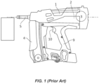
- a known tool is generally illustrated in Figure 1 , including a housing 1 with a handle 9 for grasping and handling and shooting, on which is mounted a trigger 10.
- the tool is gas-powered, i.e. the housing 1 is provided with an internal combustion engine 2 to generate a driving force for propulsion of a piston designed to drive a nail into the work surface.
- the engine 2 includes at least one combustion chamber 3 adapted to contain a mixture of fluids suitable for combustion. Igniting the mixture by an internal ignition device provides a driving force, thereby propelling the piston to drive the nail through the exit of a guide tip 5. Ignition of the ignition device is initiated by the user depressing the trigger 10 so as to generate an electric arc in the combustion chamber.
- a combustible fluid mixture typically an air and fuel mixture
- Fuel such as a combustible gas or liquid
- Air may be drawn into the combustion chamber 3 from the surrounding atmosphere by an electric fan.
- a known problem of such fastener tools is that combustion is often not optimized, thus, reducing tool efficiency, which leads to a loss of power in the tool and therefore to poor fastening quality, or even having no explosion. Also, currently available tools are not capable to adapt to different environmental conditions (e.g. varying atmospheric pressure and/or temperature) leading to a potentially ineffective and poor performance.
- a fastener driving tool comprising:
- the ionization current measurement mechanism enables the detection of anomalies in the combustion by measuring the ionization current in the chamber under compression and after the spark, as well as the detection of the type of anomaly, for example a misfire corresponding to the failure of a combustion, or soot generated by the ignition device (for instance a spark plug) or occurrence of ringing within the combustion chamber.
- said mechanism to measure a ionization current within the combustion chamber comprise a ionization sensor.
- the fastener driving tool comprises a mechanism to generate a signal representative of an information measured by the ionization sensor.
- said information measured by the ionisation sensor comprise any one of (i) a dysfunction of the ignition, and (ii) an improper use of said fastener driving tool by a user.
- the senor can detect dysfunction of the ignition such as ringing as well as misfiring and any other incorrect actuation.
- the fastener driving tool further comprises:
- the fastener driving tool comprises a mechanism to deactivate the fan assembly, said mechanism to deactivate the fan assembly comprising a switch between the fan assembly and a power supply.
- said first fluid is ambient air.
- said second fluid is a combustible fuel.
- the combustion chamber comprises an outlet port comprising a third actuator which is adapted to switch between an 'open state', in which combustion chamber is vented to the atmosphere, and a 'closed state' in which said combustion chamber (110) is prevented from venting.
- the terms 'connected', 'attached', 'coupled', 'operated' are intended to include direct connections between two members without any other members interposed therebetween, as well as, indirect connections between members in which one or more other members are interposed therebetween.
- the terminology includes the words specifically mentioned above, derivatives thereof, and words of similar import.
- the fastener driving tool 100 includes a combustion chamber 110 with first and second inlet ports 120, 130 for inputting respective first and second fluids into the combustion chamber 110.
- the first fluid may be air
- the second fluid may be a standard fuel.
- the first inlet port 120 includes a first actuator 122
- the second inlet port 130 includes a second actuator 132.
- Each one of the first and second actuators 122, 132 is adapted to switch between an open state, allowing the respective first or second fluid to move into the combustion chamber 110 at a respective first or second mass flow rate, and a closed state, in which respective first and second fluid is prevented from moving into the combustion chamber 110.
- a controller (not shown) is configured to operate any one of the first and second actuators 122, 132 and control the time interval of the 'open state(s)' based on at least one predetermined parameter in order to provide a predetermined mass ratio of the first and second fluids within the combustion chamber 110.
- the first actuator is a fan assembly 122 that is configured to switch between an open and a closed state.
- the fan assembly 122 When in the 'open state' the fan assembly 122 is activated so as to draw in air from the ambient atmosphere and move it into the combustion chamber 110.
- the fastener driving tool 100 comprises a mechanism to deactivate the fan assembly 122 when in said first 'closed state'.
- the fastener driving tool 100 comprises a mechanism to activate and/or deactivate the fan assembly 122.
- the fan assembly 122 is deactivated. Activation and deactivation of the fan 122 may simply be provided by a switch between the fan assembly 122 and its power supply.
- the second actuator may be a valve assembly 132 configured to switch between an 'open state' and a 'closed state'.
- the valve assembly 132 is operably connected to a fuel source, for example, in the form of a pressurised cartridge adapted to provide combustible fluid at constant, elevated pressure.
- a fuel source for example, in the form of a pressurised cartridge adapted to provide combustible fluid at constant, elevated pressure.
- the valve assembly 132 allows combustible fluid to move into the combustion chamber 110 from the fuel source.
- the fuel source is isolated from the combustion chamber 110.
- combustion chamber 110 is provided with an outlet port 140 having a third actuator 142 that is adapted to switch between an 'open state', in which combustion chamber 110 is vented to the atmosphere, and a 'closed state' in which the actuator 132 prevents venting.
- the fastener driving tool 100 is further provided with a cylinder 112 extending between the combustion chamber 110 at a proximal end of the cylinder 112 and an exit 116 at a distal end.
- the exit 116 leads to a guide tip on the front of the fastener driving tool 100 adapted to direct a fastener (e.g. nail) into a work surface.
- a piston 114 is provided in the cylinder 112, adapted to move from the proximal end towards the distal end under a driving force provided from within the combustion chamber 110.
- the piston 114 is designed to drive a fastener (not illustrated) into a work surface.
- An ignition device 110 such as, for example, a spark plug 1101, is provided within the combustion chamber 110, adapted to generate an electric arc (i.e. a spark) in order to ignite within the combustion chamber 110 the mixture of said first fluid and said second fluid.
- the spark plug 1101 ignites the combustible fluid mixture within the combustion chamber 110. Ignition is typically initiated by the user depressing a trigger of the fastener driving tool 100.
- the fastener driving tool 100 further comprises a mechanism to measure a ionization current (e.g. an ionisation sensor) 1102 within the combustion chamber 110. Said mechanism to measure a ionization current within the combustion chamber 110 comprises an ionization sensor 1102.
- the ionisation sensor 1102 is one as known in the art and is suitable for a spark plug or ignition system of a combustion system.
- the ignition system comprises, inter alia, an inductor or solenoid having a primary and secondary coil.
- the ionisation sensor 1102 may be provided by operably coupling the secondary coil to the spark plug, as well as, a measurement circuit for measuring the ionisation current.
- the measurement circuit may comprise an amplifier for amplifying the ionisation current and a converter for converting the ionisation current into voltage signal.
- the tool 100 further comprises a mechanism to generate a signal representative of an information measured by the ionization sensor 1102.
- the information measured by the ionisation sensor may comprise information of any one of a dysfunction of the ignition and the improper use of the tool 100 by an operator.
- the ionisation current measured within the combustion chamber 110 can be utilised as an indication of the quality of the ignition within the tool 100.
- the present disclosure allows for (i) the detection of potential anomalies within the combustion chamber 110 by simply measuring the ionization current within the combustion chamber 110 under compression and after the spark ignition, as well as, (ii) the detection of the type of anomaly, for example, a misfire corresponding to failure of combustion, or soot generated by the ignition device (i.e. the spark plug) or the occurrence of ringing noise (knocking) within the combustion chamber 110.
- the type of anomaly for example, a misfire corresponding to failure of combustion, or soot generated by the ignition device (i.e. the spark plug) or the occurrence of ringing noise (knocking) within the combustion chamber 110.
- control system 150 is provided with a controller 152 configured to provide independent digital output signals to first and second power drivers 124, 134.
- control system 150 is configured to control and power the spark plug 1101, as well as, the ionisation sensor 1102 and comprises a mechanism to process at least an information measured by the ionisation sensor 1102.
- such information may be a dysfunction of the ignition, such as, for example, a ringing or misfiring, but also any other faulty actuation.
- the information may also be based on an improper use of the fastener driving tool 100 by a user.
- Other information may be anomalies during the combustion by measuring the ionization current within the combustion chamber 110 under compression and after spark ignition, as well as, the detection of the type of anomaly, for example a misfire corresponding to the failure of a combustion, or soot generated by the ignition device (for instance a spark plug) or occurrence of ringing within the combustion chamber 110.
- control system 150 of the present disclosure comprises a mechanism configured to count and record any ignition dysfunction (or anomalies of the combustion) occurrences or any information representative of ignition dysfunction (or anomalies of the combustion) occurrences, and provide a signal representative of any one of the information extracted.
- the control system 150 is further adapted to transmit a signal to a remote network, to a user receiver, and/or to a display (e.g. a maintenance signal) or any other suitable user interface adapted to notify the user of an occurrence or fault in the tool (e.g. an LED lamp coupled to the tool for a visual indication of a fault or improper use).
- the output signal provided to the first power driver 124 causes the first power driver 124 to switch the fan assembly 122 between its 'open state' and 'closed state'.
- the controller 152 is able to control the time intervals for respective 'open state' and 'closed state' of the fan assembly 122.
- the controller 152 monitors (the controller comprises a mechanism to monitor the electric current consumed by the first actuator 122) the electric current consumed by the fan assembly 122 via sensor 126 (the mechanism to monitor the electric current consumed by the first actuator comprise a sensor). This information can be used to generate a feedback signal from the sensor to the controller 152 via a signal convertor 154. The controller 152 is thus able to determine the electric current consumed by the fan assembly 122 during its 'open state' or 'closed state'.
- the output signal provided to the second power driver 134 causes the second power driver 134 to switch the valve assembly 132 between its 'open state' and its 'closed state'.
- the controller 152 controls the time interval of respective 'open state', as well as, 'closed state' of the valve assembly 132.
- the controller 152 comprises a mechanism to control the time interval of respective 'second open state' and 'second closed state' of the valve assembly 132 (second actuator).
- the combustion chamber 110 is prepared for a firing cycle by inputting a mixture of air and fuel to the chamber 110.
- the controller 152 provides an output signal to the first power driver 124 causing the fan assembly 122 to switch to an 'open state' and thereby move air into the combustion chamber 110.
- the controller 152 provides an output signal to the second power driver 134 causing the valve assembly 132 to switch into an 'open state' and thereby move fuel into the combustion chamber 110.
- the controller 152 provides the output signals sequentially so that air is provided to the combustion chamber 110 before fuel.
- the controller 152 may provide output signal(s) which provide the air and fuel in any suitable sequence, including wholly or partly within the same time period.
- the fan assembly 122 draws air into the combustion chamber 110 at a first mass flow rate.
- the specific mass flow rate during an individual 'open state' is dependent on the characteristics of the ambient air itself at that time.
- the inventor has appreciated that the first mass flow rate depends on the ambient atmospheric pressure.
- the atmospheric pressure is low, for example, if the fastener driving tool 100 is used at high altitude, then the air density is relatively low and the electrical current consumed by the fan assembly 122 is correspondingly lower (compared to a standard mass flow rate at standard environmental conditions).
- atmospheric pressure is high, for example, if the fastener driving tool 100 is used at low altitude, then the air density is higher and the electrical current consumed by the fan assembly 122 is correspondingly higher.
- the controller 152 is able to determine the air mass flow rate and the mass of air inputted into the combustion chamber 110 for the upcoming firing cycle (e.g. interpolation from the performance data of the fan assembly at different electrical current consumptions).
- the elevated pressure of the fuel source causes combustible fluid to move into combustion chamber 110 at a predetermined fuel mass flow rate.
- the time interval for the second 'open state' is determined by the controller 152 based on the feedback signal of the sensor 126 (i.e. the current air mass flow rate and the amount of air moving into the chamber) in order to adapt the mass of fuel moved into the combustion chamber 110, so as to optimise the fuel/air mixture for optimal combustion. Therefore, an optimum fuel/air mixture is provided irrespective of the ambient atmospheric pressure or any other environmental parameter.
- the firing cycle commences igniting the mixture by the ignition device, generating a driving force to propel the piston and drive a fastener into a work surface.
- the controller 152 switches the fan assembly 132 into an 'open state' to simultaneously draw fresh air into the combustion chamber 110 and displace the combusted fluids vented through the outlet port 140. With the combusted fluids purged, the controller 152 is ready to initiate preparation for the next firing cycle.
- the controller 152 bases the time interval of the valve assembly 'open state' on the electrical current consumed by the fan assembly 122 during preparation for the firing stage. In other words, the electrical current consumed by the fan assembly 122 when the outlet port 140 is closed.
- the controller 150 may base the time interval on the current consumed by the fan assembly 122 when the third actuator 142 is open.
- the controller 152 may respond to feedback from the sensor 126 when the fan assembly 122 is providing air to displace combusted fluids in the combustion chamber.
- the controller 152 may evaluate, whether the third actuator 142 is in an 'open state' or 'closed state', in order to determine its response to the feedback of the sensor 126.
- the control system 150 may base a time interval ('closed state' and/or 'open state') of either one of the first or second actuator 122, 132 on any other indicator signal suitable for determining the ambient atmospheric pressure.
- the indicator may be a direct measurement, for example, from a pressure sensor directly coupled to the control system 150, or a pressure measurement from a pressurised fluid source.
- the indicator signal may be provided by one or more indirect measurement, such as, for example, the rotational speed of the fan assembly 122, or a flow rate measurement device suitably positioned e.g. at the inlet port of the fan assembly 122.
- the indicator signal may also be provided from a remote sensor, for example, atmospheric data provided from another device over a suitable wired or wireless connection, e.g. a mobile phone application.
- control system 150 may base the time interval of the 'open state' of any one of the first or second actuator 122, 132 on any other data suitable to derive the amount of air and/or fuel mass moved into the combustion chamber 110 at a predetermined time interval, e.g. ambient temperature or relative humidity.
- Any indicator signal, data or measurement provided to the control system 150 may be provided directly or via a suitable intermediary module, for example an analogue-to-digital convertor or wireless receiver.
- Any suitable actuators capable of providing fluids to the combustion chamber may be used, in any appropriate combination.
- the control system 150 controls the time interval of the second actuator 132 based on a parameter associated with the first actuator 122, so that the time interval of the constant pressure fuel source is controlled depending on a variable characteristic of the ambient atmospheric air.
- a parameter associated with the first actuator 122 controls either one (or both) of the time intervals to be controlled based on characteristics of one or both fluids.
- the time interval of the actuator inputting a fluid with a variable characteristic, such as air may be based on the fixed pressure and time interval of a fluid provided from a pressurised fluid cartridge.
- many variations and combinations of parameters and controls may be adapted in order that the final mixture of fluids within the combustion chamber contains an optimum mass ratio for the specific fluids being used.
- control system 150 may adapt to varying fluids such that the time intervals may be adjusted to provide different mass ratios depending on the fluids being used.
Landscapes
- Engineering & Computer Science (AREA)
- Chemical & Material Sciences (AREA)
- Combustion & Propulsion (AREA)
- Mechanical Engineering (AREA)
- Portable Nailing Machines And Staplers (AREA)
Claims (9)
- Eintreibwerkzeug für Befestigungselemente (100), aufweisend:eine Brennkammer (110) mit einer ersten Einlassöffnung (120) zur Zufuhr eines ersten Fluids mit zumindest einer variablen Fluideigenschaft und einer zweiten Einlassöffnung (130) zur Zufuhr eines zweiten Fluids;einen Kolben (114), der so ausgebildet ist, dass er ein Befestigungselement in eine Arbeitsfläche eintreibt;eine Zündvorrichtung (1101), die dazu ausgebildet ist, einen elektrischen Lichtbogen in der Brennkammer (110) zu erzeugen, um in der Brennkammer (110) ein Gemisch des ersten Fluids und des zweiten Fluids zu zünden;dadurch gekennzeichnet, dass das Eintreibwerkzeug für Befestigungselemente ferner Einrichtungen zum Messen eines Ionisationsstroms (1102) in der Brennkammer (110) aufweist.
- Eintreibwerkzeug für Befestigungselemente nach Anspruch 1, wobei die Einrichtungen zum Messen eines Ionisationsstroms in der Brennkammer einen Ionisationssensor (1102) aufweisen.
- Eintreibwerkzeug für Befestigungselemente nach Anspruch 2, ferner aufweisend eine Einrichtung zum Erzeugen eines Signals, das eine Information darstellt, die durch den Ionisationssensor gemessen wird.
- Eintreibwerkzeug für Befestigungselemente nach Anspruch 3, wobei die durch den Ionisationssensor gemessenen Informationen (i) eine Störung bei der Zündung und/oder (ii) einen nicht ordnungsgemäßen Gebrauch des Eintreibwerkzeugs für Befestigungselemente durch einen Benutzer aufweisen.
- Eintreibwerkzeug für Befestigungselemente nach einem der vorhergehenden Ansprüche, ferner Folgendes aufweisend:eine Gebläseanordnung (122), die mit der ersten Einlassöffnung (120) wirksam verbunden ist, die so ausgebildet ist, dass sie zwischen einem ersten offenen Zustand, der ermöglicht, dass sich das erste Fluid in die Brennkammer bewegt, und einem ersten geschlossenen Zustand wechselt, der verhindert, dass sich das erste Fluid in die Brennkammer (110) bewegt, oder diese Bewegung zumindest begrenzt;ein Fluidventil (132), das mit der zweiten Einlassöffnung (130) wirksam verbunden ist, das so ausgebildet ist, dass es zwischen einem zweiten offenen Zustand, der ermöglicht, dass sich das zweite Fluid in die Brennkammer (110) bewegt, und einem zweiten geschlossenen Zustand, der verhindert, dass sich das zweite Fluid in die Brennkammer bewegt, wechselt, undeine Steuerung (152), die so ausgebildet ist, dass sie entweder die Gebläseanordnung oder das Fluidventil betreibt und ein Zeitintervall des ersten offenen Zustands und/oder des zweiten offenen Zustands steuert.
- Eintreibwerkzeug für Befestigungselemente nach Anspruch 5, ferner Einrichtungen zum Deaktivieren der Gebläseanordnung (122) aufweisend, wobei die Einrichtungen zur Deaktivierung der Gebläseanordnung einen Schalter zwischen der Gebläseanordnung (122) und einer Stromversorgung aufweisen.
- Eintreibwerkzeug für Befestigungselemente nach einem der vorhergehenden Ansprüche, wobei das erste Fluid Umgebungsluft ist.
- Eintreibwerkzeug für Befestigungselemente nach einem der vorherigen Ansprüche, wobei das zweite Fluid ein Brennstoff ist.
- Eintreibwerkzeug für Befestigungselemente nach einem der vorhergehenden Ansprüche, wobei die Brennkammer (110) eine Auslassöffnung (140) aufweist, die einen dritten Aktor (142) aufweist, der so ausgebildet ist, dass er zwischen einem "offenen Zustand", in dem die Brennkammer (110) in die Atmosphäre entlüftet wird, und einem "geschlossenen Zustand", in dem die Brennkammer (110) am Entlüften gehindert wird, umschaltet.
Applications Claiming Priority (2)
| Application Number | Priority Date | Filing Date | Title |
|---|---|---|---|
| EP21175847 | 2021-05-26 | ||
| PCT/US2022/030671 WO2022251174A1 (en) | 2021-05-26 | 2022-05-24 | Fastener driving tool |
Publications (2)
| Publication Number | Publication Date |
|---|---|
| EP4347191A1 EP4347191A1 (de) | 2024-04-10 |
| EP4347191B1 true EP4347191B1 (de) | 2025-04-23 |
Family
ID=76137921
Family Applications (1)
| Application Number | Title | Priority Date | Filing Date |
|---|---|---|---|
| EP22730655.2A Active EP4347191B1 (de) | 2021-05-26 | 2022-05-24 | Eintreibgerät für befestigungsmittel |
Country Status (5)
| Country | Link |
|---|---|
| US (1) | US20240269813A1 (de) |
| EP (1) | EP4347191B1 (de) |
| AU (1) | AU2022280778A1 (de) |
| CA (1) | CA3220906A1 (de) |
| WO (1) | WO2022251174A1 (de) |
Family Cites Families (7)
| Publication number | Priority date | Publication date | Assignee | Title |
|---|---|---|---|---|
| US6123241A (en) * | 1995-05-23 | 2000-09-26 | Applied Tool Development Corporation | Internal combustion powered tool |
| JP4395841B2 (ja) * | 2004-09-29 | 2010-01-13 | 日立工機株式会社 | 燃焼式打込み工具 |
| JP2008018513A (ja) * | 2006-07-14 | 2008-01-31 | Makita Corp | 燃焼式作業工具 |
| JP5064958B2 (ja) * | 2007-10-04 | 2012-10-31 | 株式会社マキタ | 打ち込み工具 |
| WO2009088896A1 (en) * | 2008-01-04 | 2009-07-16 | Illinois Tool Works Inc. | Combustion chamber and cooling system for fastener-driving tools |
| CN201917606U (zh) * | 2010-08-20 | 2011-08-03 | 朱益民 | 一种燃气钉枪高压放电检测保护电路及燃气钉枪 |
| US10584653B2 (en) * | 2017-11-27 | 2020-03-10 | Innio Jenbacher Gmbh & Co Og | Systems and methods for spark timing retardation |
-
2022
- 2022-05-24 AU AU2022280778A patent/AU2022280778A1/en active Pending
- 2022-05-24 WO PCT/US2022/030671 patent/WO2022251174A1/en not_active Ceased
- 2022-05-24 EP EP22730655.2A patent/EP4347191B1/de active Active
- 2022-05-24 CA CA3220906A patent/CA3220906A1/en active Pending
- 2022-05-24 US US18/561,222 patent/US20240269813A1/en active Pending
Also Published As
| Publication number | Publication date |
|---|---|
| WO2022251174A1 (en) | 2022-12-01 |
| CA3220906A1 (en) | 2022-12-01 |
| US20240269813A1 (en) | 2024-08-15 |
| EP4347191A1 (de) | 2024-04-10 |
| AU2022280778A1 (en) | 2023-12-07 |
Similar Documents
| Publication | Publication Date | Title |
|---|---|---|
| US7980440B2 (en) | Combustion-engined setting tool | |
| CN101498267B (zh) | 用于点火液喷射器的检验方法 | |
| US4913331A (en) | Internal-combustion piston driving apparatus having a decompression channel | |
| AU2019200366B2 (en) | Driving tool | |
| US20040134961A1 (en) | Combustion-engined setting tool | |
| EP0056989A2 (de) | Tragbares, gasgetriebenes Werkzeug mit Linearmotor | |
| EP2136059A1 (de) | Mikropilotinjektions-gasmotor | |
| US11338422B2 (en) | Driving tool | |
| EP2921679B1 (de) | Zündaussetzererkennung in einer mit gas betriebenen brennkraftmaschine | |
| KR20090126291A (ko) | 가스 내연식 정타기 | |
| JP2009190166A (ja) | 燃焼力駆動式打ち込み装置 | |
| CN106460767A (zh) | 用于确定火花电压的检测系统 | |
| EP4347191B1 (de) | Eintreibgerät für befestigungsmittel | |
| US8561867B2 (en) | Gas combustion type fastener driving machine | |
| US7000405B2 (en) | Gas turbine apparatus and a starting method thereof | |
| EP3954504B1 (de) | Werkzeug zum eintreiben von befestigungselementen | |
| EP1608489B1 (de) | Verfahren zur Einstellung der Kraft einer mit Gas-betriebenen Einrichtung | |
| JP5189317B2 (ja) | 燃焼力作動型鋲打ち機 | |
| EP1606081B1 (de) | Gasdruckvorrichtungen mit einem vorkompressionsraum und einer brennkammer | |
| JPH0643822B2 (ja) | ガスエンジンの失火制御装置 | |
| JP7004154B2 (ja) | ガス燃焼式打込み工具 | |
| JP2001507428A (ja) | 燃焼センサーフィードバックシステムの診断装置 |
Legal Events
| Date | Code | Title | Description |
|---|---|---|---|
| STAA | Information on the status of an ep patent application or granted ep patent |
Free format text: STATUS: UNKNOWN |
|
| STAA | Information on the status of an ep patent application or granted ep patent |
Free format text: STATUS: THE INTERNATIONAL PUBLICATION HAS BEEN MADE |
|
| PUAI | Public reference made under article 153(3) epc to a published international application that has entered the european phase |
Free format text: ORIGINAL CODE: 0009012 |
|
| STAA | Information on the status of an ep patent application or granted ep patent |
Free format text: STATUS: REQUEST FOR EXAMINATION WAS MADE |
|
| 17P | Request for examination filed |
Effective date: 20231116 |
|
| AK | Designated contracting states |
Kind code of ref document: A1 Designated state(s): AL AT BE BG CH CY CZ DE DK EE ES FI FR GB GR HR HU IE IS IT LI LT LU LV MC MK MT NL NO PL PT RO RS SE SI SK SM TR |
|
| DAV | Request for validation of the european patent (deleted) | ||
| DAX | Request for extension of the european patent (deleted) | ||
| GRAP | Despatch of communication of intention to grant a patent |
Free format text: ORIGINAL CODE: EPIDOSNIGR1 |
|
| STAA | Information on the status of an ep patent application or granted ep patent |
Free format text: STATUS: GRANT OF PATENT IS INTENDED |
|
| INTG | Intention to grant announced |
Effective date: 20241217 |
|
| P01 | Opt-out of the competence of the unified patent court (upc) registered |
Free format text: CASE NUMBER: APP_3000/2025 Effective date: 20250117 |
|
| GRAS | Grant fee paid |
Free format text: ORIGINAL CODE: EPIDOSNIGR3 |
|
| GRAA | (expected) grant |
Free format text: ORIGINAL CODE: 0009210 |
|
| STAA | Information on the status of an ep patent application or granted ep patent |
Free format text: STATUS: THE PATENT HAS BEEN GRANTED |
|
| AK | Designated contracting states |
Kind code of ref document: B1 Designated state(s): AL AT BE BG CH CY CZ DE DK EE ES FI FR GB GR HR HU IE IS IT LI LT LU LV MC MK MT NL NO PL PT RO RS SE SI SK SM TR |
|
| REG | Reference to a national code |
Ref country code: GB Ref legal event code: FG4D |
|
| REG | Reference to a national code |
Ref country code: CH Ref legal event code: EP |
|
| REG | Reference to a national code |
Ref country code: DE Ref legal event code: R096 Ref document number: 602022013605 Country of ref document: DE |
|
| REG | Reference to a national code |
Ref country code: IE Ref legal event code: FG4D |
|
| PGFP | Annual fee paid to national office [announced via postgrant information from national office to epo] |
Ref country code: DE Payment date: 20250627 Year of fee payment: 4 |
|
| PGFP | Annual fee paid to national office [announced via postgrant information from national office to epo] |
Ref country code: FR Payment date: 20250625 Year of fee payment: 4 |
|
| PGFP | Annual fee paid to national office [announced via postgrant information from national office to epo] |
Ref country code: AT Payment date: 20250721 Year of fee payment: 4 |
|
| REG | Reference to a national code |
Ref country code: NL Ref legal event code: MP Effective date: 20250423 |
|
| PG25 | Lapsed in a contracting state [announced via postgrant information from national office to epo] |
Ref country code: NL Free format text: LAPSE BECAUSE OF FAILURE TO SUBMIT A TRANSLATION OF THE DESCRIPTION OR TO PAY THE FEE WITHIN THE PRESCRIBED TIME-LIMIT Effective date: 20250423 |
|
| REG | Reference to a national code |
Ref country code: AT Ref legal event code: MK05 Ref document number: 1787344 Country of ref document: AT Kind code of ref document: T Effective date: 20250423 |
|
| PG25 | Lapsed in a contracting state [announced via postgrant information from national office to epo] |
Ref country code: FI Free format text: LAPSE BECAUSE OF FAILURE TO SUBMIT A TRANSLATION OF THE DESCRIPTION OR TO PAY THE FEE WITHIN THE PRESCRIBED TIME-LIMIT Effective date: 20250423 Ref country code: ES Free format text: LAPSE BECAUSE OF FAILURE TO SUBMIT A TRANSLATION OF THE DESCRIPTION OR TO PAY THE FEE WITHIN THE PRESCRIBED TIME-LIMIT Effective date: 20250423 Ref country code: PT Free format text: LAPSE BECAUSE OF FAILURE TO SUBMIT A TRANSLATION OF THE DESCRIPTION OR TO PAY THE FEE WITHIN THE PRESCRIBED TIME-LIMIT Effective date: 20250825 |
|
| REG | Reference to a national code |
Ref country code: LT Ref legal event code: MG9D |
|
| PG25 | Lapsed in a contracting state [announced via postgrant information from national office to epo] |
Ref country code: GR Free format text: LAPSE BECAUSE OF FAILURE TO SUBMIT A TRANSLATION OF THE DESCRIPTION OR TO PAY THE FEE WITHIN THE PRESCRIBED TIME-LIMIT Effective date: 20250724 Ref country code: NO Free format text: LAPSE BECAUSE OF FAILURE TO SUBMIT A TRANSLATION OF THE DESCRIPTION OR TO PAY THE FEE WITHIN THE PRESCRIBED TIME-LIMIT Effective date: 20250723 |
|
| PG25 | Lapsed in a contracting state [announced via postgrant information from national office to epo] |
Ref country code: PL Free format text: LAPSE BECAUSE OF FAILURE TO SUBMIT A TRANSLATION OF THE DESCRIPTION OR TO PAY THE FEE WITHIN THE PRESCRIBED TIME-LIMIT Effective date: 20250423 |
|
| PG25 | Lapsed in a contracting state [announced via postgrant information from national office to epo] |
Ref country code: BG Free format text: LAPSE BECAUSE OF FAILURE TO SUBMIT A TRANSLATION OF THE DESCRIPTION OR TO PAY THE FEE WITHIN THE PRESCRIBED TIME-LIMIT Effective date: 20250423 |
|
| PG25 | Lapsed in a contracting state [announced via postgrant information from national office to epo] |
Ref country code: HR Free format text: LAPSE BECAUSE OF FAILURE TO SUBMIT A TRANSLATION OF THE DESCRIPTION OR TO PAY THE FEE WITHIN THE PRESCRIBED TIME-LIMIT Effective date: 20250423 Ref country code: AT Free format text: LAPSE BECAUSE OF FAILURE TO SUBMIT A TRANSLATION OF THE DESCRIPTION OR TO PAY THE FEE WITHIN THE PRESCRIBED TIME-LIMIT Effective date: 20250423 |
|
| PG25 | Lapsed in a contracting state [announced via postgrant information from national office to epo] |
Ref country code: RS Free format text: LAPSE BECAUSE OF FAILURE TO SUBMIT A TRANSLATION OF THE DESCRIPTION OR TO PAY THE FEE WITHIN THE PRESCRIBED TIME-LIMIT Effective date: 20250723 |
|
| PG25 | Lapsed in a contracting state [announced via postgrant information from national office to epo] |
Ref country code: IS Free format text: LAPSE BECAUSE OF FAILURE TO SUBMIT A TRANSLATION OF THE DESCRIPTION OR TO PAY THE FEE WITHIN THE PRESCRIBED TIME-LIMIT Effective date: 20250823 |
|
| PG25 | Lapsed in a contracting state [announced via postgrant information from national office to epo] |
Ref country code: LV Free format text: LAPSE BECAUSE OF FAILURE TO SUBMIT A TRANSLATION OF THE DESCRIPTION OR TO PAY THE FEE WITHIN THE PRESCRIBED TIME-LIMIT Effective date: 20250423 |
|
| REG | Reference to a national code |
Ref country code: CH Ref legal event code: H13 Free format text: ST27 STATUS EVENT CODE: U-0-0-H10-H13 (AS PROVIDED BY THE NATIONAL OFFICE) Effective date: 20251223 |
|
| PG25 | Lapsed in a contracting state [announced via postgrant information from national office to epo] |
Ref country code: SM Free format text: LAPSE BECAUSE OF FAILURE TO SUBMIT A TRANSLATION OF THE DESCRIPTION OR TO PAY THE FEE WITHIN THE PRESCRIBED TIME-LIMIT Effective date: 20250423 Ref country code: DK Free format text: LAPSE BECAUSE OF FAILURE TO SUBMIT A TRANSLATION OF THE DESCRIPTION OR TO PAY THE FEE WITHIN THE PRESCRIBED TIME-LIMIT Effective date: 20250423 |
|
| PG25 | Lapsed in a contracting state [announced via postgrant information from national office to epo] |
Ref country code: LU Free format text: LAPSE BECAUSE OF NON-PAYMENT OF DUE FEES Effective date: 20250524 |
|
| PG25 | Lapsed in a contracting state [announced via postgrant information from national office to epo] |
Ref country code: CH Free format text: LAPSE BECAUSE OF NON-PAYMENT OF DUE FEES Effective date: 20250531 |
|
| PG25 | Lapsed in a contracting state [announced via postgrant information from national office to epo] |
Ref country code: CZ Free format text: LAPSE BECAUSE OF FAILURE TO SUBMIT A TRANSLATION OF THE DESCRIPTION OR TO PAY THE FEE WITHIN THE PRESCRIBED TIME-LIMIT Effective date: 20250423 |
|
| PG25 | Lapsed in a contracting state [announced via postgrant information from national office to epo] |
Ref country code: EE Free format text: LAPSE BECAUSE OF FAILURE TO SUBMIT A TRANSLATION OF THE DESCRIPTION OR TO PAY THE FEE WITHIN THE PRESCRIBED TIME-LIMIT Effective date: 20250423 |
|
| REG | Reference to a national code |
Ref country code: DE Ref legal event code: R097 Ref document number: 602022013605 Country of ref document: DE |
|
| PG25 | Lapsed in a contracting state [announced via postgrant information from national office to epo] |
Ref country code: SK Free format text: LAPSE BECAUSE OF FAILURE TO SUBMIT A TRANSLATION OF THE DESCRIPTION OR TO PAY THE FEE WITHIN THE PRESCRIBED TIME-LIMIT Effective date: 20250423 |
|
| PG25 | Lapsed in a contracting state [announced via postgrant information from national office to epo] |
Ref country code: IT Free format text: LAPSE BECAUSE OF FAILURE TO SUBMIT A TRANSLATION OF THE DESCRIPTION OR TO PAY THE FEE WITHIN THE PRESCRIBED TIME-LIMIT Effective date: 20250423 |
|
| REG | Reference to a national code |
Ref country code: BE Ref legal event code: MM Effective date: 20250531 |
|
| PG25 | Lapsed in a contracting state [announced via postgrant information from national office to epo] |
Ref country code: MC Free format text: LAPSE BECAUSE OF FAILURE TO SUBMIT A TRANSLATION OF THE DESCRIPTION OR TO PAY THE FEE WITHIN THE PRESCRIBED TIME-LIMIT Effective date: 20250423 |
|
| PLBE | No opposition filed within time limit |
Free format text: ORIGINAL CODE: 0009261 |
|
| STAA | Information on the status of an ep patent application or granted ep patent |
Free format text: STATUS: NO OPPOSITION FILED WITHIN TIME LIMIT |
|
| REG | Reference to a national code |
Ref country code: CH Ref legal event code: L10 Free format text: ST27 STATUS EVENT CODE: U-0-0-L10-L00 (AS PROVIDED BY THE NATIONAL OFFICE) Effective date: 20260304 |
|
| PG25 | Lapsed in a contracting state [announced via postgrant information from national office to epo] |
Ref country code: RO Free format text: LAPSE BECAUSE OF FAILURE TO SUBMIT A TRANSLATION OF THE DESCRIPTION OR TO PAY THE FEE WITHIN THE PRESCRIBED TIME-LIMIT Effective date: 20250423 |