EP4346309A1 - Procédé de gestion d'une planification multicellulaire et équipement utilisateur - Google Patents
Procédé de gestion d'une planification multicellulaire et équipement utilisateur Download PDFInfo
- Publication number
- EP4346309A1 EP4346309A1 EP23198596.1A EP23198596A EP4346309A1 EP 4346309 A1 EP4346309 A1 EP 4346309A1 EP 23198596 A EP23198596 A EP 23198596A EP 4346309 A1 EP4346309 A1 EP 4346309A1
- Authority
- EP
- European Patent Office
- Prior art keywords
- cell
- dci
- indicator
- srs resource
- field
- Prior art date
- Legal status (The legal status is an assumption and is not a legal conclusion. Google has not performed a legal analysis and makes no representation as to the accuracy of the status listed.)
- Pending
Links
- 238000000034 method Methods 0.000 title claims abstract description 63
- 238000004891 communication Methods 0.000 claims abstract description 49
- 230000005540 biological transmission Effects 0.000 claims description 43
- 230000011664 signaling Effects 0.000 claims description 13
- 230000001174 ascending effect Effects 0.000 claims description 6
- 238000013468 resource allocation Methods 0.000 claims description 5
- 238000010586 diagram Methods 0.000 description 46
- 239000010410 layer Substances 0.000 description 24
- 238000013507 mapping Methods 0.000 description 17
- ZIEXYIQTFZVRBI-UHFFFAOYSA-N 2-[(4-bromophenyl)methoxy]acetic acid Chemical compound OC(=O)COCC1=CC=C(Br)C=C1 ZIEXYIQTFZVRBI-UHFFFAOYSA-N 0.000 description 3
- 125000004122 cyclic group Chemical group 0.000 description 3
- OQEBBZSWEGYTPG-UHFFFAOYSA-N 3-aminobutanoic acid Chemical compound CC(N)CC(O)=O OQEBBZSWEGYTPG-UHFFFAOYSA-N 0.000 description 2
- CIWBSHSKHKDKBQ-JLAZNSOCSA-N Ascorbic acid Chemical compound OC[C@H](O)[C@H]1OC(=O)C(O)=C1O CIWBSHSKHKDKBQ-JLAZNSOCSA-N 0.000 description 2
- 238000004590 computer program Methods 0.000 description 2
- 238000005516 engineering process Methods 0.000 description 2
- 230000002085 persistent effect Effects 0.000 description 2
- 238000012545 processing Methods 0.000 description 2
- 239000002356 single layer Substances 0.000 description 2
- 101000741965 Homo sapiens Inactive tyrosine-protein kinase PRAG1 Proteins 0.000 description 1
- 102100038659 Inactive tyrosine-protein kinase PRAG1 Human genes 0.000 description 1
- 230000003044 adaptive effect Effects 0.000 description 1
- 230000006399 behavior Effects 0.000 description 1
- 230000001419 dependent effect Effects 0.000 description 1
- 238000013461 design Methods 0.000 description 1
- 230000000694 effects Effects 0.000 description 1
- 230000007774 longterm Effects 0.000 description 1
- 238000010295 mobile communication Methods 0.000 description 1
- 238000000638 solvent extraction Methods 0.000 description 1
Images








Classifications
-
- H—ELECTRICITY
- H04—ELECTRIC COMMUNICATION TECHNIQUE
- H04W—WIRELESS COMMUNICATION NETWORKS
- H04W72/00—Local resource management
- H04W72/20—Control channels or signalling for resource management
- H04W72/23—Control channels or signalling for resource management in the downlink direction of a wireless link, i.e. towards a terminal
-
- H—ELECTRICITY
- H04—ELECTRIC COMMUNICATION TECHNIQUE
- H04W—WIRELESS COMMUNICATION NETWORKS
- H04W72/00—Local resource management
- H04W72/20—Control channels or signalling for resource management
- H04W72/23—Control channels or signalling for resource management in the downlink direction of a wireless link, i.e. towards a terminal
- H04W72/232—Control channels or signalling for resource management in the downlink direction of a wireless link, i.e. towards a terminal the control data signalling from the physical layer, e.g. DCI signalling
-
- H—ELECTRICITY
- H04—ELECTRIC COMMUNICATION TECHNIQUE
- H04L—TRANSMISSION OF DIGITAL INFORMATION, e.g. TELEGRAPHIC COMMUNICATION
- H04L5/00—Arrangements affording multiple use of the transmission path
- H04L5/003—Arrangements for allocating sub-channels of the transmission path
- H04L5/0048—Allocation of pilot signals, i.e. of signals known to the receiver
-
- H—ELECTRICITY
- H04—ELECTRIC COMMUNICATION TECHNIQUE
- H04L—TRANSMISSION OF DIGITAL INFORMATION, e.g. TELEGRAPHIC COMMUNICATION
- H04L5/00—Arrangements affording multiple use of the transmission path
- H04L5/003—Arrangements for allocating sub-channels of the transmission path
- H04L5/0053—Allocation of signalling, i.e. of overhead other than pilot signals
-
- H—ELECTRICITY
- H04—ELECTRIC COMMUNICATION TECHNIQUE
- H04W—WIRELESS COMMUNICATION NETWORKS
- H04W72/00—Local resource management
- H04W72/04—Wireless resource allocation
- H04W72/044—Wireless resource allocation based on the type of the allocated resource
- H04W72/0446—Resources in time domain, e.g. slots or frames
-
- H—ELECTRICITY
- H04—ELECTRIC COMMUNICATION TECHNIQUE
- H04W—WIRELESS COMMUNICATION NETWORKS
- H04W72/00—Local resource management
- H04W72/04—Wireless resource allocation
- H04W72/044—Wireless resource allocation based on the type of the allocated resource
- H04W72/0453—Resources in frequency domain, e.g. a carrier in FDMA
-
- H—ELECTRICITY
- H04—ELECTRIC COMMUNICATION TECHNIQUE
- H04W—WIRELESS COMMUNICATION NETWORKS
- H04W72/00—Local resource management
- H04W72/04—Wireless resource allocation
- H04W72/044—Wireless resource allocation based on the type of the allocated resource
- H04W72/0457—Variable allocation of band or rate
-
- H—ELECTRICITY
- H04—ELECTRIC COMMUNICATION TECHNIQUE
- H04W—WIRELESS COMMUNICATION NETWORKS
- H04W72/00—Local resource management
- H04W72/12—Wireless traffic scheduling
-
- H—ELECTRICITY
- H04—ELECTRIC COMMUNICATION TECHNIQUE
- H04W—WIRELESS COMMUNICATION NETWORKS
- H04W72/00—Local resource management
- H04W72/12—Wireless traffic scheduling
- H04W72/1263—Mapping of traffic onto schedule, e.g. scheduled allocation or multiplexing of flows
-
- H—ELECTRICITY
- H04—ELECTRIC COMMUNICATION TECHNIQUE
- H04W—WIRELESS COMMUNICATION NETWORKS
- H04W72/00—Local resource management
- H04W72/20—Control channels or signalling for resource management
- H04W72/23—Control channels or signalling for resource management in the downlink direction of a wireless link, i.e. towards a terminal
- H04W72/231—Control channels or signalling for resource management in the downlink direction of a wireless link, i.e. towards a terminal the control data signalling from the layers above the physical layer, e.g. RRC or MAC-CE signalling
Definitions
- the present disclosure generally relates to a method for handling a multi-cell scheduling and a user equipment (UE).
- UE user equipment
- FIG. 1 is a schematic diagram that illustrates an example of multi-cell communications.
- transmission reception point (TRP)#1 provides four cells Cell#0 ⁇ Cell#3, and TRP#2 provides two cells Cell#0 ⁇ Cell#1.
- TRP transmission reception point
- one or some of the cells Cell#0 ⁇ Cell#3 may support multi-panel operation, but others may support single-panel operation.
- the legacy DCI does not provide a proper field in the control signaling to indicate multi-panel operation for multi-cell scheduling.
- the present disclosure is directed to a method for handling a multi-cell scheduling and a UE.
- a method for handling a multi-cell scheduling is used by a UE.
- the method includes: receiving a downlink control information (DCI) from a first serving cell; determining a first number of multiple scheduled cells according to the DCI, where the DCI is configured to schedule at least one communication on the scheduled cells; and performing the at least one communication on at least one of the first number of the scheduled cells according to the DCI.
- the DCI includes at least one single DCI field, at least one separate DCI field, and at least one configurable DCI field.
- a UE includes a transceiver, a memory, and a processor.
- the transceiver is used for transmitting or receiving signals.
- the memory is used for storing a program code.
- the processor is coupled to the transceiver and the memory.
- the processor is configured for executing the program to: receive, through the transceiver, a DCI from a first serving cell; determine a first number of multiple scheduled cells according to the DCI, where the DCI is configured to schedule at least one communication on the scheduled cells; and perform the at least one communication on at least one of the first number of the scheduled cells according to the DCI.
- the DCI includes at least one single DCI field, at least one separate DCI field, and at least one configurable DCI field.
- a method for handling a multi-cell scheduling is used by a network device.
- the method includes: configuring a DCI scheduling a first number of multiple scheduled cells; and transmitting the DCI via a first serving cell to a UE for performing multiple multi-cell communications on the scheduled cells.
- the DCI includes at least one a single DCI field, at least one separate DCI field, and at least one configurable DCI field.
- a DCI in this disclosure may also known as a DCI format.
- a DCI or DCI format in this disclosure may also known as a PDCCH.
- the DCI for multi-cell scheduling may be monitored in USS set.
- the DCI for multi-cell scheduling may be a DCI format with CRC scrambled by a C-RNTI.
- a PUSCH may be transmitted in a UL BWP of a serving cell.
- a BWP is a contiguous set of PRB(s) on a given carrier.
- UE can be configured with maximum 4 BWP for Downlink and Uplink but at a given point of time only one BWP is active for downlink and one for uplink.
- Each BWP defined for numerology may have different Subcarrier spacing, Symbol duration, and/or Cyclic prefix (CP) length.
- a serving cell in this disclosure may be also known as a cell, a carrier, or a component carrier.
- the maximum number of co-scheduled cells by a DCI is 4.
- the multiple PUSCH are scheduled in multiple serving cell (e.g., one PUSCH per cell) by a DCI.
- the maximum number of co-scheduled cells by a DCI format may be smaller than or equal to the maximum number of co-scheduled cells supported by the network or gNB.
- the scheduling cell and scheduled cell may be configured in a cell group.
- the cell group for example, may be a PUCCH group.
- the co-scheduled cells may be configured with the same SCS configuration.
- the scheduling cell and co-scheduled cells may be configured with the same SCS configuration.
- a type-1 field may be treated as a common field or 1st field; a type-2 field may be treated as a separate field or 2nd field and a type-3 field may be treated as a configurable field or 3rd field. But not limited herein.
- At least one PUSCH on a serving cell is scheduled by a DCI, and the DCI can schedule PUSCH(s) on one cell (i.e., a single cell scheduling DCI).
- New DCI format with a new type (Type-3) of DCI field New DCI format with a new type (Type-3) of DCI field.
- Multi-panel operation with multi-cell scheduling needs to be supported.
- a new DCI format is introduced.
- different TBs are respectively scheduled on different cells by DCI format 0_X. In one embodiment, different TBs are respectively scheduled on different cells by DCI format 1_X.
- the DCI for multi-cell scheduling is monitored only in the USS set.
- all the co-scheduled cells by a DCI format 0_X/1_X and the scheduling cell are included in the same PUCCH group.
- DCI format 0_X/1_X on a scheduling cell can be used to schedule PUSCHs/PDSCHs on multiple cells including the scheduling cell.
- DCI format 0_X/1_X on a scheduling cell can be used to schedule PUSCHs/PDSCHs on multiple cells not including the scheduling cell.
- the maximum number of cells scheduled by a DCI format 0_X can be the same or different from the maximum number of cells scheduled by a DCI format 1_X.
- the UE may determine a number of co-scheduled serving cell (e.g., X0 for DCI format 0_X and X1 for DCI format 1_X) according to gNB configuration (e.g., SS configuration) or indicated by the DCI format 0_X/1_X.
- a number of co-scheduled serving cell e.g., X0 for DCI format 0_X and X1 for DCI format 1_X
- gNB configuration e.g., SS configuration
- the UE may determine a set of candidate cells that can be co-scheduled by the DCI format, where:
- one sub-group includes a subset of co-scheduled cells where a single field is commonly applied to the co-scheduled cell(s) belonging to a same sub-group.
- the co-scheduled cells are indicated by DCI format 0_X/1_X. At least the following options are considered:
- a DCI size alignment is performed over all search spaces configured at a BWP and across all slots, then for a given DCI format at a given search space, the DCI size is the same across slots.
- there is no slot-by-slot dependence (other than for BWP switching or when some RRC configurations become invalid based on specifications).
- a UE may expect to monitor PDCCH candidates for up to 4 sizes of DCI formats that include up to 3 sizes of DCI formats with CRC scrambled by C-RNTI per serving cell. The UE counts a number of sizes for DCI formats per serving cell based on a number of configured PDCCH candidates in respective search space sets for the corresponding active DL BWP.
- FIG. 2 is a schematic diagram that illustrates DCI size alignment.
- fallback DCIs e.g., formats 0_0 and 1_0
- the size alignment is performed among fallback DCIs in CSS.
- fallback DCIs monitored in a USS are determined, and the size alignment is performed among the fallback DCIs in USS.
- the non-fallback DCIs i.e., formats 0_1 and 1_1
- the non-fallback DCIs should have a different size from the fallback DCI in USS (by adding padding bit if necessary.
- Step 2A the non-fallback DCIs (i.e., formats 0_2 and 1_2) monitored in a USS are determined, and the non-fallback DCI should have a different size from the fallback DCI in USS (e.g., by adding padding bit if necessary.
- Step 3 whether both of the following conditions are fulfilled is determined:
- Step 4A the padding bit introduced in Step 2 and Step 2A is removed, the fallback DCIs monitored in a USS are determined, and the size alignment is performed among the fallback DCIs in the USS.
- Step 4B whether the following conditions are fulfilled is determined:
- Step 4C whether the following conditions are fulfilled is determined:
- FIG. 3 is a schematic diagram that illustrates DCI size alignment for each step.
- the lengths of DCI formats 0_0 and 1_0 in CSS are determined as size A
- the lengths of DCI formats 0_0 and 1_0 in USS are determined as size B
- the length of DCI format 0_1 is determined as size C
- the length of DCI format 1_1 is determined as size D
- the length of DCI format 0_2 is determined as size E
- the length of DCI format 1_2 is determined as size F.
- the lengths of DCI formats 0_0 and 1_0 in USS are aligneded as size A.
- Step 4B the lengths of DCI formats 0_2 and 1_1 are aligned as size G.
- Step S4C the lengths of DCI formats 0_1 and 1_1 are aligned as size H.
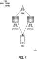
- FIG. 4 is a schematic diagram that illustrates a radio communication network architecture 1 according to an exemplary embodiment of the present disclosure.
- a radio communication network architecture e.g., a Long Term Evolution (LTE) system, an LTE-Advanced (LTE-A) system, an LTE-Advanced Pro system, or a 5G NR Radio Access Network (RAN)
- LTE Long Term Evolution
- LTE-A LTE-Advanced
- RAN 5G NR Radio Access Network
- the UE communicates with the network (e.g., a Core Network (CN), an Evolved Packet Core (EPC) network, an Evolved Universal Terrestrial Radio Access network (E-UTRAN), a 5G Core (5GC), or an internet), through a RAN established by one or more base stations.
- CN Core Network
- EPC Evolved Packet Core
- E-UTRAN Evolved Universal Terrestrial Radio Access network
- 5GC 5G Core
- UE may include, but is not limited to, a mobile station, a mobile terminal or device, or a user communication radio terminal.
- UE may be a portable radio equipment, which includes, but is not limited to, a mobile phone, a tablet, a wearable device, a sensor, a vehicle, or a Personal Digital Assistant (PDA) with wireless communication capability.
- PDA Personal Digital Assistant
- the UE is configured to receive and transmit signals over an air interface to one or more cells in a radio access network.
- a base station NW may be configured to provide communication services according to at least one of the following Radio Access Technologies (RATs): Worldwide Interoperability for Microwave Access (WiMAX), Global System for Mobile communications (GSM, often referred to as 2G), GSM Enhanced Data rates for GSM Evolution (EDGE) Radio Access Network (GERAN), General Packet Radio Service (GPRS), Universal Mobile Telecommunication System (UMTS, often referred to as 3G) based on basic wideband-code division multiple access (W-CDMA), high-speed packet access (HSPA), LTE, LTE-A, eLTE (evolved LTE, e.g., LTE connected to 5GC), NR (often referred to as 5G), and/or LTE-A Pro.
- RATs Radio Access Technologies
- a base station NW may include but is not limited to, a node B (NB) as in the UMTS, an evolved node B (eNB) as in the LTE or LTE-A, a radio network controller (RNC) as in the UMTS, a base station controller (BSC) as in the GSM/ GSM Enhanced Data rates for GSM Evolution (EDGE) Radio Access Network (GERAN), a next-generation eNB (ng-eNB) as in an Evolved Universal Terrestrial Radio Access (E-UTRA) BS in connection with the 5GC, a next-generation Node B (gNB) as in the 5G Access Network (5G-AN), and any other apparatus capable of controlling radio communication and managing radio resources within a cell.
- the BS NW may connect to serve one or more UEs through a radio interface to the network.
- the base station (BS) NW may be operable to provide radio coverage to a specific geographical area using a plurality of cells included in the RAN.
- the BS NW may support the operations of the cells.
- Each cell may be operable to provide services to at least one UE within its radio coverage.
- each cell (often referred to as a serving cell) may provide services to serve one or more UEs within its radio coverage (e.g., each cell schedules the Downlink (DL) and optionally Uplink (UL) resources to at least one UE within its radio coverage for DL and optionally UL packet transmission).
- the BS NW may communicate with one or more UEs in the radio communication system through the plurality of cells.
- the base station NW may include a network node NN and one or more TRPs, such as TRP#1 and TRP#2.
- a network node NN may be, but is not limited to, a node B (NB) as in the LTE, an evolved node B (eNB) as in the LTE-A, a radio network controller (RNC) as in the UMTS, a base station controller (BSC) as in the GSM/GERAN, a new radio evolved node B (NR eNB) as in the NR, a next generation node B (gNB) as in the NR, and any other apparatus capable of controlling radio communication and managing radio resources within one or more cells.
- NB node B
- eNB evolved node B
- RNC radio network controller
- BSC base station controller
- NR eNB new radio evolved node B
- gNB next generation node B
- a TRP (e.g., TRP#1 or TRP#2), which may also be regarded as a remote radio head (RRH), may be a transceiver under the protocols of 5G NR wireless communication system and/or the protocols of a 4G wireless communication system.
- a TRP may be communicatively connected to a network node NN.
- the network node NN may connect to serve one or more UEs through one or more TRPs in the radio communication system.
- TRP#1 and TRP#2 serve UE, but are not limited thereto.
- the frame structure for NR is to support flexible configurations for accommodating various next generation (e.g., 5G) communication requirements, such as Enhanced Mobile Broadband (eMBB), Massive Machine Type Communication (mMTC), Ultra-Reliable and Low-Latency Communication (URLLC), while fulfilling high reliability, high data rate and low latency requirements.
- 5G next generation
- eMBB Enhanced Mobile Broadband
- mMTC Massive Machine Type Communication
- URLLC Ultra-Reliable and Low-Latency Communication
- OFDM Orthogonal Frequency-Division Multiplexing
- the scalable OFDM numerology such as the adaptive sub-carrier spacing, the channel bandwidth, and the Cyclic Prefix (CP) may also be used.
- two coding schemes are considered for NR: (1) Low-Density Parity-Check (LDPC) code and (2) Polar Code.
- the coding scheme adaption may be configured based on the channel conditions and/or the service applications.
- system and “network” used in the disclosure are often used interchangeably.
- the term “and/or” in the disclosure is only an association relationship describing the associated objects, which means that there can be three kinds of relationships, for example, A and/or B, which can mean three situations: A is present alone, A and B are present simultaneously, or B is present alone.
- the character "/" in the disclosure generally indicates that the associated objects are in an "or” relationship.
- a UE may determine the length (e.g., L) for a DCI format (e.g., DCI format 0_X/1_X) according to one or more higher layer configurations.
- a higher layer configuration e.g., a SS configuration
- the length of DCI format 0_X/1_X may not equal the length for other DCI formats with CRC scrambled by C-RNTI.
- the length of DCI format 0_X/1_X may equal the length for other DCI formats with CRC scrambled by e.g., SFI-RNTI, INT-RNTI, CI-RNTI, TPC-PUCCH-RNTI, TPC-PUSCH-RNTI and/or TPC-SRS-RNTI.
- the DCI format 0_X and DCI format 1_X may be configured with the same length or different lengths.
- the length of the DCI format (e.g., DCI format 0_X/DCI format 1_X) may not equal to other DCI format(s) (e.g., DCI format 0_0/0_1, DCI format 0_1/1_1 and/or DCI format 0_2/1_2).
- the length of DCI format 0_1/1_1 may equal the length of DCI format 0_2/1_2.
- the length of the DCI format (e.g., DCI format 0_X/DCI format 1_X) may equal to other DCI format(s) (e.g., DCI format 0_0/0_1, DCI format 0_1/1_1 and/or DCI format 0_2/1_2), for example, after a DCI size alignment.
- DCI format 0_X/DCI format 1_X may equal to other DCI format(s) (e.g., DCI format 0_0/0_1, DCI format 0_1/1_1 and/or DCI format 0_2/1_2), for example, after a DCI size alignment.
- FIG. 5 is a schematic diagram that illustrates DCI size alignment for each step according to an exemplary embodiment of the present disclosure.
- the length of DCI format 0_X is determined as size E'
- the length of DCI format 1_X is determined as size F' which may equal E'.
- the length of DCI formats 0_X and 1_X may be aligned as size I.
- the lengths of DCI formats 0_1, 1_1, 0_2, and 1_2 are aligned as size K which equals the largest one of size G and size H.
- FIG. 6 is a schematic diagram that illustrates DCI size alignment for each step according to an exemplary embodiment of the present disclosure.
- step 4D the lengths of the DCI formats 0_X and 1_X are aligned as size K which equals the largest one of size G and size H.
- Step 4D there are three different DCI sizes, and the conditions of Step 3 are fulfilled.
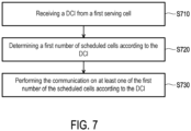
- FIG. 7 is a flow chart that illustrates a method for handling a multi-cell scheduling according to an exemplary embodiment of the present disclosure.
- the method is adapted for a UE.
- the UE receives a DCI from a serving cell (Step S710).
- the first serving cell is provided by TRP#1 or TRP#2 as shown in FIG. 4 .
- the UE determines the first number of multiple scheduled cells according to the DCI (Step S720).
- the DCI is configured to schedule UE with one or more communications such as receiving PDSCH or transmitting PUSCH on the scheduled cells.
- the first number is a positive integer.
- the UE may determine the first number of the scheduled cells from a third number of scheduled cells.
- the third number is a positive integer.
- the first number is less than or equals to the third number. For example, the first number is 3, and the third number is 4.
- the maximum number of the third number of serving cells is 4, and/or the minimum number of the first number of serving cells is 1.
- the UE performs one or more communications on one or more of the first number of the scheduled cells according to the DCI (Step S730).
- the DCI includes one or more single DCI fields, one or more separate DCI fields, and one or more configurable DCI fields.
- FIG. 8 is a schematic diagram that illustrates DCI fields for scheduling the communications on four cells according to an exemplary embodiment of the present disclosure.
- a DCI bit stream there may be multiple common fields (i.e., the single DCI field), multiple separate fields (i.e., the separate DCI fields), and multiple type-3 fields (i.e., the configurable DCI fields).
- Each type-3 field could be a common, separate, or per sub-group information.
- the following types of DCI fields may be used for a DCI format for multi-cell scheduling:
- one sub-group may include a subset of co-scheduled cells where a single DCI field is commonly applied to the co-scheduled cell(s) belonging to the same sub-group.
- the single DCI field may:
- the following information is transmitted by means of the DCI format:
- the following information is transmitted by means of the DCI format:
- the single DCI field corresponds to one, some, or all of the first number of the scheduled cells on which the UE performs one or more communications (such as receiving PDSCH or transmitting PUSCH). That is when or only when the single DCI field indicates information for the scheduled cells from the first number of the scheduled cells, the UE may receive PDSCH or transmit PUSH on the scheduled cells which are indicated in the single DCI field.
- the common field indicates information for Cell#1 ⁇ Cell#4.
- Cell#1 ⁇ Cell#4 are co-scheduled cells indicated by the DCI. Therefore, a UE, which received the DCI, may receive PDSCH or transmit PUSH on Cell#1 ⁇ Cell#4.
- FIG. 9 is a schematic diagram that illustrates DCI fields for three cells according to an exemplary embodiment of the present disclosure.
- the common field indicates information for Cell#1 ⁇ Cell#3.
- Cell#1 ⁇ Cell#3 are co-scheduled cells indicated by the DCI. Therefore, a UE, which received the DCI, may receive PDSCH or transmit PUSH on Cell#1 ⁇ Cell#3.
- FIG. 10 is a schematic diagram that illustrates DCI fields for three cells according to an exemplary embodiment of the present disclosure.
- the common field indicates information for Cell#A ⁇ Cell#C.
- Cell#A ⁇ Cell#C are co-scheduled cells indicated by the DCI. Therefore, a UE, which received the DCI, may receive PDSCH or transmit PUSH on Cell#A ⁇ Cell#C.
- the single DCI field may include at least one of:
- the separate DCI field corresponds to a second number of information blocks, and each information block indicates control information for one of the scheduled cells.
- the separate fields indicate control information for Cell#1 ⁇ Cell#4 per information block, respectively. That is four information blocks correspond to Cell#1 ⁇ Cell#4, respectively.
- the separate fields indicate control information for Cell#1 ⁇ Cell#3 per information block, respectively.
- the separate fields indicate control information for Cell#A ⁇ Cell#C per information block, respectively.
- the second number equals to the first number. For example, if there are four scheduled cells, the DCI includes separate DCI field with four information blocks.
- the second number of information blocks are placed according to an ascending order of a serving cell index
- the first information block corresponds to the smallest serving cell index.
- the ascending order is #1, #2, #3, and #4.
- the first information block corresponds to Cell#1.
- the ascending order is #A, #B, and #C.
- the first information block corresponds to Cell#A.
- the order of the information blocks may be placed according to a descending order or another order of the serving cell index.
- control information corresponds to one of the following:
- a UE may determine whether a type-3 field (e.g., the configurable field) is a common field or a separate field to each of the first number of scheduled cells (e.g., the co-scheduled cells), or a separate field to each sub-group, according to a higher layer configuration.
- a type-3 field e.g., the configurable field
- the first number of scheduled cells e.g., the co-scheduled cells
- a UE may determine one of one or more configurable DCI fields corresponding to the first number of the scheduled cells in an event that the configurable DCI field is a first type, and the UE may determine one of one or more configurable DCI fields including multiple information blocks in which each information block corresponding to a sub-group or one of the first number of the scheduled cells in an event that the configurable DCI field is a second type.
- the first type is the aforementioned type-1 or common type
- the second type is the aforementioned type-2 or the separate type.
- the (N-1) th type-3 field is the common DCI field
- the common field corresponds to all Cell#1 ⁇ Cell#4.
- the N th type-3 fields are the separate fields, where each information block of the separate fields corresponds to one sub-group.
- One sub-group may be any combination of Cell#1 ⁇ Cell#4 based on a higher layer configuration.
- the first type-3 fields are separate fields, where each information block of the separate fields corresponds to one of Cell#A-Cell#C.
- the UE may receive a higher layer (e.g., SS configuration) configuration to determine whether the DCI field is common filed (Case 1), separate field (Case 2) or common filed for a sub-group (Case 3) of co-scheduled cell.
- the configuration may include at least one of:
- the configurable DCI field comprises at least one of:
- each of the set of DCI fields indicates common information for a sub-group of the first number of the scheduled cells (e.g., co-scheduled cells).
- a set of SRI fields includes 2 SRIs, where the first SRI indicates common information for a first sub-group of co-scheduled cells, and the second SRI indicates common information for a second sub-group of co-scheduled cells.
- the PRB bundling size indicator includes 2 bits, where the first bit indicates a first PRB bundling size for a first sub-group of co-scheduled cells, and the second bit indicates a first PRB bundling size for a second sub-group subset of co-scheduled cells.
- a subset of co-scheduled cells may include one serving cell, for example, the aforementioned first serving cell.
- a subset of co-scheduled cells may include all co-scheduled cells. Taking FIG. 9 as an example, a subset of co-scheduled cells includes Cell#1 ⁇ Cell#3.
- a UE when a UE is configured with a DCI format for multi-cell PUSCH/PDSCH scheduling (e.g., from M candidate serving cells). For each of the scheduled serving cell(s), the UE may determine the TDRA according to a common TDRA field in the DCI format. For example, in Table (1), each codepoint of the TDRA field may include at least one of K0 (or K2), SLIV, and mapping type for each of the M candidate serving cells. M may be a predetermined value, fixed value, or configured by the network device. The UE may determine a TDRA for each of the scheduled serving cell(s) according to their own TDRA configuration and numerology (e.g., SCS) of PDCCH and PUSCH/PDSCH.
- SCS numerology
- FIG. 11 is a schematic diagram that illustrates DCI fields with joint indication according to an exemplary embodiment of the present disclosure.
- a DCI indicates a multi-cell PDSCH transmission on Cell B and Cell C (selected from cell A ⁇ Cell E), and the TDRA field indicates 3. Therefore, the UE may determine the TDRA according to K0 B,3 and SLIV B,3 for the PDSCH transmissions on Cell B and determine the TDRA according to K0 C,3 and SLIV C,3 for the PDSCH transmissions on Cell C.
- a UE may apply one of one or more configurable DCI fields to the scheduled cells in an event that type information is absent from one of the configurable DCI fields.
- the type information indicates one of one or more configurable DCI fields as one of one or more single DCI fields, and/or the type information indicates one of one or more configurable DCI fields as one of one or more separate DCI fields.
- Each configurable DCI field has corresponding type information.
- the type information is provided via a higher layer signaling.
- the event is that, for example, gNB does not configure the type information for one of the configurable DCI field via a higher layer signaling, or DCI does not carry the type information or has no corresponding field of the type information.
- the DCI has a corresponding field of the type information, but the field is configured as zero, null, or invalid.
- the UE may treat the type-3 field as a common field.
- the common field indicates information for one or more co-scheduled cells.
- a UE may determine one of one or more configurable DCI fields corresponding to a second number of information blocks in an event that type information is absent from one of one or more configurable DCI fields.
- the type information indicates one of one or more configurable DCI fields as one of one or more single DCI fields or one of one or more separate DCI fields.
- Each configurable DCI field has corresponding type information.
- the type information is provided via a higher layer signaling.
- the event is that, for example, gNB does not configure the type information for one of the configurable DCI field via a higher layer signaling, or DCI does not carry the type information or has no corresponding field of the type information.
- the DCI has a corresponding field of the type information, but the field is configured as zero, null, or invalid.
- the UE may treat the type-3 field as a separate field.
- Each separate field indicates control information for one co-scheduled cell.
- the second number equals to the first number.
- the DCI is configured in a UE-specific search space (USS) and the length of the DCI is determined according to one or more higher layer configurations.
- the higher layer configuration is the USS configuration.
- the DCI is scrambled by a cell-radio network temporary identity (C-RNTI) and the length of the DCI is not equal to the length of a first DCI (i.e., another DCI) with a different format scrambled by the C-RNTI.
- C-RNTI cell-radio network temporary identity
- a UE may determine the length of information blocks in the separate DCI field or in the configurable DCI field to be the same.
- the length of each separate DCI field or each configurable DCI field is predetermined. Taking FIG. 8 as an example, the length of the four information blocks of separate fields respectively for Cell#1 ⁇ Cell#4 is the same.
- a UE may determine the length of a information block in the separate DCI field or in the configurable DCI field according to one or more higher-layer signaling.
- One higher layer signaling is used for one of the information blocks corresponding to a scheduled cell. For example, a RRC configuration indicates the length of the information block in one field.
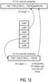
- FIG. 12 is a schematic diagram that illustrates mismatched DCI lengths according to an exemplary embodiment of the present disclosure.
- the length of DCI is configured as L for three cells such as Cell#1 ⁇ Cell#3.
- This length may not be adapted for four cells such as Cell#3 ⁇ Cell#6, and a corresponding DCI filed of Cell#6 may be not in the DCI format.
- a UE may apply a default value for the control information of the DCI in an event that the control information is absent from the DCI.
- the event is that, for example, DCI does not carry one piece of control information corresponding to a scheduled cell or has no corresponding field of the control information.
- the event is that, for example, DCI does not carry valid control information corresponding to a scheduled cell.
- a default value of the control information is applied for Cell#6.
- a default value/pattern or a default UE behavior may be applied.
- a UE may apply a default value/pattern for "RV” (e.g., 0 or gNB configured value) if the indicator is not in the DCI format; apply a default value/pattern for "Antenna ports” (e.g., "00" or gNB configured value) if the indicator is not in the DCI format, apply a default value/pattern for "TPMI” (e.g., "0000") if the TPMI is not in the DCI format, assume a single antenna port transmission for a PUSCH if corresponding "TPMI” is not in the DCI format, apply a default spatial relation for a PUSCH if corresponding "SRI” is not in the DCI format, and/or apply a default spatial
- a UE may not perform one of one or more communications on one of the scheduled cells in an event that control information for one of the scheduled cells is absent from the DCI.
- the event is that, for example, DCI does not carry one piece of control information corresponding to a scheduled cell or has no corresponding field of the control information.
- the UE may not perform PUSCH transmission or PDSCH reception on Cell#6 when or only when a specific DCI field (e.g., TDRA, FDRA, MCS, etc.) corresponding to the Cell#6 is not in the DCI format, and/ or when or only when the UE is not capable to follow the instruction without sufficient DCI.
- a specific DCI field e.g., TDRA, FDRA, MCS, etc.
- a UE may apply a quasi Co-Location (QCL) assumption for a physical downlink shared channel (PDSCH) in one or more communications based on a transmission configuration indicator (TCI) state with the lowest identification (ID) applicable for the PDSCH in an event that TCI state is absent from the DCI.
- TCI transmission configuration indicator
- ID identification
- the event is that, for example, DCI does not carry the TCI state or has no corresponding field of the TCI state.
- the event is that, for another example, the DCI has a corresponding field of the TCI state, but the field is configured as zero, null, or invalid.
- the UE In a situation where the UE receives a DCI on one serving cell, and one of one or more PDSCHs (e.g., PDSCH#1) scheduled by that DCI is performed on the same serving cell.
- the UE cannot obtain TCI field corresponding to the serving cell by the DCI (e.g., due to the limitation of DCI length).
- the UE may determine the PDSCH QCL assumption based on the CORESET with a CORESET ID (e.g., lowest CORESET ID). Otherwise, the UE may determine the PDSCH QCL assumption based on the CORESET transmitting the DCI that schedules the PDSCH.
- a UE receives a DCI on one serving cell, and one of the PDSCHs (e.g., PDSCH#1) scheduled by that DCI is performed on another serving cell.
- the UE may obtain its QCL assumption for the scheduled PDSCH (e.g., PDSCH#1) from the activated TCI state with an ID (e.g., lowest ID) applicable to PDSCH in the active BWP of the scheduled cell.
- the UE may be configured by a higher layer signaling to enable Default Beam for CCS (e.g., enableDefaultBeamForCCS).
- a UE may apply a sounding reference signal (SRS) resource indicator (SRI) to one or more physical uplink shared channel (PUSCH) repetitions or to one or more PUSCHs according to one SRS resource set in an event that the SRS resource set is configured. That is one SRS resource set is configured for a serving cell, i.e., single panel.
- the SRI is given by the first DCI field including one SRS resource indicator and the first DCI field is in the DCI.
- Table (2) is a mapping table between the spatial relation of PUSCH and SRI.
- a UE may apply an SRI to one or more PUSCH repetitions or to one or more PUSCHs according to one SRS resource set in an event that the SRS resource set is configured in an event an SRS resource set indicator is absent in the DCI.
- the event is that, for example, DCI does not carry the SRS resource set indicator or has no corresponding field of the SRS resource set indicator.
- the event is that, for another example, the DCI has a corresponding field of the SRS resource set indicator, but the field is configured as zero, null, or invalid.
- a UE may apply an SRI to one or more physical uplink shared channel (PUSCH) repetitions or to one or more PUSCHs according to the first one of multiple SRS resource sets in an event that the SRS resource sets are configured. That is multiple SRS resource sets are configured, i.e., multi-panel.
- PUSCH physical uplink shared channel
- FIG. 13B is a schematic diagram that illustrates multi-panel operation according to an exemplary embodiment of the present disclosure.
- two SRS resource sets which are the first and the second SRS resource sets, are configured for a serving cell.
- Table (3) is a spatial relation of PUSCH repetition and SRS resource set indicator.
- SRS resource set indicator PUSCH repetition scheme 00 AAAA... 01 BBBB... 10 ABAB... or AABB 11 BABA... or BBAA
- the spatial relation of PUSCH repetition corresponds to the first SRS resource set.
- Multiple “A” in Table (3) represent multiple continuous PUSCHs (i.e., PUSCH repetition) performed associating to the first SRS resource set.
- the SRS resource set indicator "01" is indicated in the first DCI field in a DCI
- the spatial relation of PUSCH repetition corresponds to the second SRS resource set.
- Multiple “B” in Table (3) represent multiple continuous PUSCHs (i.e., PUSCH repetition) performed associating tothe second SRS resource set.
- the spatial relation of PUSCH repetition corresponds to the first and the second SRS resource sets, respectively.
- a UE may determine a spatial relation (e.g., X or Y) of PUSCH according to the SRI as mentioned in the aforementioned embodiment corresponding to FIG. 13A .
- UE may apply an SRI to one or more PUSCH repetitions or to one or more PUSCHs according to the first one of multiple SRS resource sets in an event that the SRS resource sets are configured.
- the SRS resource set indicator does not exist in the DCI when two SRS resource sets are configured
- the PUSCH repetition or PUSCH may be performed based on SRI as shown in Table (2).
- one or more PUSCHs may be one or more PUSCH repetitions for a TB.
- FIG. 14 is a schematic diagram that illustrates a relation determination according to an exemplary embodiment of the present disclosure.
- Cell#0 ⁇ Cell#3 are the candidate cells for multi-cell scheduling.
- the DCI indicates PUSCH repetition with the same TB for Cell#2, such as PUSCH#20 at slot n and PUSCH#21 at slot n +1 .
- one or more PUSCHs may correspond to one or more TBs.
- DCI may indicate two PUSCHs with different TBs for Cell#3, such as PUSCH#30 at slot n and PUSCH#31 at slot n +1 .
- determining a spatial relation for at least one PUSCH according to one of the following:
- the UE when a UE is indicated by a DCI to transmit one or more PUSCHs on a serving cell, the UE may determine a spatial relation for one or more PUSCH according to a spatial setting/relation of a reference/co-scheduled serving cell.
- the reference/co-scheduled serving cell may be configured by a network device or according to a predetermined rule (e.g., the lowest cell-ID among co-scheduled cells).
- the reference/co-scheduled cell may be indicated with a spatial relation via a SRI field in the DCI.
- FIG. 15 is a schematic diagram that illustrates a relation determination for one sound reference signal (SRS) resource set configured for a serving cell according to an exemplary embodiment of the present disclosure.
- the DCI includes an SRI field for PUSCH#1 in Cell#0.
- Cell#0 is a reference cell of Cell#1 ⁇ Cell#3.
- UE determines a spatial relation for PUSCH#2 and PUSCH#3 according to the SRI for PUSCH#1.
- the UE may determine a spatial relation for one or more PUSCH according to a spatial relation of a PL-RS configured for the SRS resource set, or a predetermined SRI (e.g., first) associated with the SRS resource set. For example, when there is no SRI (e.g., corresponding to the serving cell) in the DCI, when there is no reference cell for determining the spatial relation, and/or when a reference cell of the serving cell is not scheduled by the DCI, the predetermined SRI would correspond to the spatial relation for PUSCH.
- SRI e.g., corresponding to the serving cell
- the UE may not transmit one or more PUSCHs when there is no SRI (e.g., corresponding to the serving cell) in the DCI.
- the UE may determine a spatial relation for one or more PUSCH according to an active PDSCH TCI state with an ID (e.g., the lowest ID) in the active DL BWP of the serving cell.
- an ID e.g., the lowest ID
- the active PDSCH TCI state with the lowest ID in the active DL BWP would correspond to the spatial relation for PUSCH.
- FIG. 16 is a schematic diagram that illustrates a relation determination for one SRS resource set configured for a serving cell according to an exemplary embodiment of the present disclosure.
- a UE may determine a spatial relation for PUSCH#1 according to an active PDSCH TCI state with the lowest ID in the active DL BWP of cell#1.
- the UE may determine a spatial relation for one or more PUSCH according to a spatial setting/relation of a PUCCH with an ID (e.g., the lowest ID). For example, when there is no SRI (e.g., corresponding to the serving cell) in the DCI, when there is no reference cell for determining the spatial relation, and/or when a reference cell of the serving cell is not scheduled by the DCI, the spatial setting/relation of a PUCCH with the lowest ID would correspond to the spatial relation for PUSCH.
- the PUCCH may be configured in the serving cell.
- the PUCCH may be configured in another serving cell and configured within the same cell group (e.g., PUCCH cell group) as the serving cell.
- a UE determines a spatial relation for PUSCH#1 according to a spatial setting/relation of a PUCCH with the lowest ID of cell#1.
- the cell#1 may be Pcell, PScell, PUCCH Scell, or PUCCH sScell.
- a UE may determine a first relation between at least one of multiple SRS resource sets and one or more PUSCH repetitions or a second relation between at least one of the SRS resource sets and one or more PUSCHs according to an SRS resource set indicator in the DCI in an event that multiple SRS resource sets are configured.
- the UE may transmit one or more PUSCH repetitions according to the first relation between at least one of the SRS resource sets and one or more PUSCH repetitions or transmit one or more PUSCHs according to the second relation between at least one of the SRS resource sets and one or more PUSCHs.
- a (e.g., multi-cell) scheduling DCI may indicate the following transmission scheme with less DCI overhead:
- a UE is indicated by a DCI to transmit one or more PUSCHs on a serving cell, and there is an SRS resource set indicator (e.g., with 2-bit) corresponding to the serving cell in the DCI. For example, if the DCI indicates codepoint "00" for the SRS resource set indicator, the first SRS resource set may be associated with one or more PUSCHs. If the DCI indicates codepoint "01" for the SRS resource set indicator, the second SRS resource set may be associated with one or more PUSCHs.
- SRS resource set indicator e.g., with 2-bit
- the first and second SRS resource sets are applied to the first and second (if any) PUSCH repetition, respectively, and the same SRS resource set mapping pattern continues to the remaining PUSCH repetition, if any. If the DCI indicates codepoint "11" for the SRS resource set indicator, the second and first SRS resource sets are applied to the first and second (if any) PUSCH repetition, respectively, and the same SRS resource set mapping pattern continues to the remaining PUSCH repetition, if any.
- a UE is indicated by a DCI to transmit one or more PUSCHs on a serving cell, and there is an SRS resource set indicator (e.g., with 1-bit) corresponding to the serving cell in the DCI. For example, if the DCI indicates codepoint "0" for the SRS resource set indicator, the first and second SRS resource sets are applied to the first and second (if any) PUSCH repetition, respectively, and the same SRS resource set mapping pattern continues to the remaining PUSCH repetition, if any.
- SRS resource set indicator e.g., with 1-bit
- the second and first SRS resource sets are applied to the first and second (if any) PUSCH repetition, respectively, and the same SRS resource set mapping pattern continues to the remaining PUSCH repetition, if any.
- FIG. 17 is a schematic diagram that illustrates a relation determination for multi-panel operation according to an exemplary embodiment of the present disclosure.
- Table (4) is a mapping table between the SRS resource set indicator and PUSCH repetition scheme. If the SRS resource set indicator is configured with codepoint "0", the PUSCH repetition pattern would be "AB" or "AABB”. If the SRS resource set indicator is configured with codepoint "1", the PUSCH repetition pattern would be "BA” or "BBAA”. Table (4) SRS resource set indicator PUSCH repetition scheme 0 ABAB... or AABB... 1 BABA... or BBAA...
- a UE is indicated by a DCI to transmit one or more PUSCHs on a serving cell, and there is an SRS resource set indicator corresponding to the serving cell in the DCI.
- the UE may determine one or more spatial relations for one or more PUSCH according to two SRIs for the serving cell in the DCI, where the first SRI may be associated with the first SRS resource set indicated in the DCI, and the second SRI may be associated with the second SRS resource set indicated in the DCI.
- a UE may determine a spatial relation for the at least one PUSCH according to one of the following:
- a predetermined SRI (e.g., first SRI) may associate with the first SRS resource set, and/or a spatial relation of a PL-RS configured for the first SRS resource set may be applied.
- a predetermined SRI (e.g., second SRI) may associate with the second SRS resource set, and/or a spatial relation of a PL-RS configured for the second SRS resource set may be applied.
- a UE may determine at least one spatial relation for one or more PUSCHs according to an active PDSCH TCI state with an ID (e.g., lowest ID) and with 2 TCI states in the active DL BWP of the serving cell, e.g., the first and second TCI states of the PDSCH TCI state ID are corresponding to the spatial relation of first and second SRS resource set, respectively.
- an ID e.g., lowest ID
- 2 TCI states in the active DL BWP of the serving cell e.g., the first and second TCI states of the PDSCH TCI state ID are corresponding to the spatial relation of first and second SRS resource set, respectively.
- a UE may determine at least one spatial relation for one or more PUSCHs according to a spatial setting/relation of a PUCCH with an ID (e.g., the lowest ID), e.g., a spatial setting/relation with a lower or higher ID configured for the PUCCH is corresponding to the spatial relation of first and second SRS resource set, respectively.
- an ID e.g., the lowest ID
- a spatial setting/relation with a lower or higher ID configured for the PUCCH is corresponding to the spatial relation of first and second SRS resource set, respectively.
- a UE may determine at least one spatial relation for one or more PUSCHs according to a (e.g., type D) QCL assumption or a spatial relation of a CORESET with an ID (e.g., the lowest ID), e.g., the first or second TCI state configured for the CORESET are corresponding to the spatial relation of first and second SRS resource set, respectively; the TCI state configured for the CORESET of a first CORESET pool index is corresponding to the spatial relation of first SRS resource set, and the TCI state configured for the CORESET of a second CORESET pool index is corresponding to the spatial relation of second SRS resource set.
- a (e.g., type D) QCL assumption or a spatial relation of a CORESET with an ID e.g., the lowest ID
- the first or second TCI state configured for the CORESET are corresponding to the spatial relation of first and second SRS resource set, respectively
- a UE may determine at least one spatial relation for one or more PUSCHs applied for the first SRS resource set according to one SRI for the serving cell in the DCI associated with the first SRS resource set.
- a UE may determine at least one spatial relation for one or more PUSCHs applied for the second SRS resource set according to a predetermined SRI (e.g., the first) associated with the second SRS resource set, a spatial relation of a PL-RS configured for the second SRS resource set, an active PDSCH TCI state with an ID (e.g., the lowest ID) and with 2 TCI states in the active DL BWP of the serving cell, a spatial setting/relation of a PUCCH with an ID (e.g., the lowest ID), and/or a (e.g., type D) QCL assumption or a spatial relation of a CORESET with an ID (e.g., the lowest ID).
- a predetermined SRI e.g., the first
- a spatial relation of a PL-RS configured for the second SRS resource set
- an active PDSCH TCI state with an ID e.g., the lowest ID
- FIG. 18 is a schematic diagram that illustrates a panel selection according to an exemplary embodiment of the present disclosure.
- a UE is indicated by a DCI to transmit at least one or more PUSCHs on a serving cell, and there is an SRS resource set indicator (e.g., with 1-bit) corresponding to the serving cell in the DCI.
- the DCI indicates codepoint "0" for the SRS resource set indicator
- the first SRS resource set may be associated with one or more PUSCHs (e.g., Case 1 in the figure).
- the second SRS resource set may be associated with one or more PUSCHs (e.g., Case 2 in the figure).
- a UE is indicated by a DCI to transmit at least one or more PUSCHs on a serving cell, and there is an SRS resource set indicator (e.g., with 1-bit) corresponding to the serving cell in the DCI.
- the UE may determine one or more spatial relations for one or more PUSCHs according to one or more SRI fields in the DCI.
- One SRI field may correspond to the serving cell.
- the UE may apply the indicated SRI to one or more PUSCHs according to the associated SRS resource set as indicated by the SRS resource set indicator.
- the serving cell may be a reference serving cell (e.g., configured by a network device or according to the cell ID) for determining an SRI for all or a sub-group of candidate serving cells. For any serving cell within the candidate cell for multi-cell scheduling (or for any cell within the same sub-group), the UE may determine a spatial relation according to the reference cell and the SRI.
- FIG. 19 is a schematic diagram that illustrates a relation determination for multi-panel operation according to an exemplary embodiment of the present disclosure.
- the SRS resource set indicator corresponding to the first SRS resource set is configured in a DCI provided by TRP#1.
- a UE is indicated by a DCI to transmit at least one or more PUSCHs on a serving cell, and there is an SRS resource set indicator (e.g., with 1-bit) corresponding to the serving cell in the DCI.
- an SRS resource set indicator e.g., with 1-bit
- the UE may determine one or more spatial relations for one or more PUSCHs according to one of the following:
- a UE is indicated by a DCI to transmit at least one or more PUSCHs on a serving cell, and there is an SRS resource set indicator (e.g., with 1-bit) corresponding to the serving cell in the DCI.
- the UE may determine one or more spatial relations for one or more PUSCHs according to a spatial relation of a PL_RS configured for the SRS resource set indicated by the SRS resource set indicator or an active PDSCH TCI state with an ID (e.g., the lowest ID) and with 2 TCI states in the active SL BWP of the serving cell (e.g., the first and second TCI states of the PDSCH TCI state ID are corresponding to the spatial relation of first and second SRS resource sets, respectively).
- the UE may assume one or more PUSCHs are scheduled with a single layer (single antenna port) transmission.
- a UE may determine the spatial relation of PUSCH as the PL_RS configured for the indicated SRS resource set in the DCI or an active PSCH TCI state with the lowest ID and 2 TCI states.
- a UE is indicated by DCI to transmit one or more PUSCHs on a serving cell, and the DCI may dynamically indicate single TRP or multi-TRP transmission for one or more PUSCHs.
- a UE may determine a spatial relation for one or more PUSCHs according to one or more demodulation reference signal (DMRS) ports indicated by an antenna port field in the DCI.
- DMRS demodulation reference signal
- FIG. 20 is a schematic diagram that illustrates a dynamic single/multi-panel operation according to an exemplary embodiment of the present disclosure.
- a DCI field in the DCI indicates a DMRS port corresponding to the first SRS resource set
- the UE may perform PUSCH transmission on the first SRS resource set.
- a DCI field in the DCI indicate DMRS ports corresponding to the first and second SRS resource sets
- the UE may perform PUSCH transmissions on the first and second SRS resource sets.
- multiple DMRS ports include two DMRS ports multiplexed in one or more symbol DMRS in a code division manner, and each DMRS port is associated with a DMRS code division multiplexing (CDM) group.
- CDM DMRS code division multiplexing
- FIG. 21 is a schematic diagram that illustrates an association of demodulation reference signals (DMRS) port and code division multiplexing (CDM) group according to an exemplary embodiment of the present disclosure.
- DMRS demodulation reference signals
- CDM code division multiplexing
- Table (5) Value Number of DMRS CDM group(s) without data DMRS port(s) SRS resource set 0 1 0 1 1 1 1 1 2 2 0 1 3 2 1 1 4 2 2 2 5 2 3 2 6-7 Reserved Reserved Reserved
- Table (6) Value Number of DMRS CDM group(s) without data DMRS port(s) SRS resource set 0 1 0,1 1 1 2 0,1 1 2 2 2,3 2 3 2 0,2 1, 2 4-7 Reserved Reserved Reserved
- Table (7) Value Number of DMRS CDM group(s) without data DMRS port(s) SRS resource set 0 2 0-2 1, 2 1-7 Reserved Reserved Reserved
- Table (8) Value Number of DMRS CDM group(s) without data DMRS port(s) SRS resource set 0 2 0-3 1, 2 1-7 Reserved Reserved Reserved
- Table (9) Value Number of DMRS CDM group(s) without data DMRS port(s) SRS resource set 0 2 0-2 1, 2 1 2 0-2 1 2 2 0-2 2 3-7 Reserved Reserved Reserved
- Table (10) Value Number of DMRS CDM group(s) without data DMRS port(s) SRS resource set 0 2 0-3 1, 2 1 2 0-3 1 2 2 0-3 2 3-7 Reserved Reserved Reserved
- FIG. 22 is a schematic diagram that illustrates an association of DMRS port and CDM group according to an exemplary embodiment of the present disclosure.
- antenna port 1000/1001/1004/1005 corresponds to the first SRS resource set
- antenna port 1002/1003/1006/1007 corresponds to the second SRS resource set.
- two DMRS ports are multiplexed in the code division manner.
- Table (11) Value Number of DMRS CDM group(s) without data DMRS port(s) Number of front-load symbols SRS resource set 0 1 0 1 1 1 1 1 1 1 2 2 0 1 1 3 2 1 1 1 4 2 2 1 2 5 2 3 1 2 6 2 0 2 1 7 2 1 2 1 8 2 2 2 2 9 2 3 2 2 10 2 4 2 1 11 2 5 2 1 12 2 6 2 2 13 2 7 2 2 14-15 Reserved Reserved Reserved Reserved Reserved Reserved Reserved Reserved
- Table (13) Value Number of DMRS CDM group(s) without data DMRS port(s) Number of front-load symbols SRS resource set 0 2 0-2 1 1, 2 1 2 0,1,4 2 1 2 2 2,3,6 2 2 3-15 Reserved Reserved Reserved Reserved Reserved
- a UE is indicated by DCI to transmit one or more PUSCHs on a serving cell, and the DCI may dynamically indicate single TRP or multi-TRP transmission for one or more PUSCHs.
- the UE may determine a spatial relation for one or more PUSCHs according to two SRIs for the serving cell in the DCI.
- the two SRIs include the first SRI and the second SRI.
- the first SRI may be associated with the first SRS resource set indicated in the DCI.
- the second SRI may be associated with the second SRS resource set indicated in the DCI.
- a UE is indicated by DCI to transmit one or more PUSCHs on a serving cell, and the DCI may dynamically indicate single TRP or multi-TRP transmission for one or more PUSCHs.
- the UE may determine a spatial relation for one or more PUSCHs applied for the first SRS resource set according to a predetermined SRI (e.g., first) associated with the first SRS resource set and/or a spatial relation of a PL-RS configured for the first SRS resource set.
- a predetermined SRI e.g., first
- a UE is indicated by DCI to transmit one or more PUSCHs on a serving cell, and the DCI may dynamically indicate single TRP or multi-TRP transmission for one or more PUSCHs.
- the UE may determine a spatial relation for one or more PUSCHs applied for the second SRS resource set according to a predetermined SRI (e.g., second) associated with the second SRS resource set and/or a spatial relation of a PL-RS configured for the second SRS resource set.
- a predetermined SRI e.g., second
- a UE is indicated by DCI to transmit one or more PUSCHs on a serving cell, and the DCI may dynamically indicate single TRP or multi-TRP transmission for one or more PUSCHs.
- the UE may determine a spatial relation for one or more PUSCHs according to at least one of the following:
- a UE is indicated by DCI to transmit one or more PUSCHs on a serving cell, and the DCI may dynamically indicate single TRP or multi-TRP transmission for one or more PUSCHs.
- the UE may apply a sounding reference signal (SRS) resource indicator (SRI) to one or more physical uplink shared channel (PUSCH) repetitions or to one or more PUSCHs according to one SRS resource set in an event that multiple SRS resource set are configured. That is one SRS resource set is utilized for transmitting one or more physical uplink shared channel (PUSCH) repetitions or transmitting one or more PUSCHs, i.e., single panel UL transmission.
- SRS sounding reference signal
- the SRI is given by the first DCI field including one SRS resource indicator and the first DCI field is in the DCI.
- the UE may determine a spatial relation for one or more PUSCHs applied for the first SRS resource set according to one SRI for the serving cell in the DCI associated with the first SRS resource set.
- a UE is indicated by DCI to transmit one or more PUSCHs on a serving cell, and the DCI may dynamically indicate single TRP or multi-TRP transmission for one or more PUSCHs.
- the UE may apply an SRI to one or more PUSCH repetitions or to one or more PUSCHs according to one SRS resource set in an event that two SRS resource sets are configured and in an event an SRS resource set indicator is absent in the DCI.
- the event is that, for example, DCI does not carry the SRS resource set indicator or has no corresponding field of the SRS resource set indicator.
- the event is that, for another example, the DCI has a corresponding field of the SRS resource set indicator, but the field is configured as zero, null, or invalid.
- a UE is indicated by DCI to transmit one or more PUSCHs on a serving cell, and the DCI may dynamically indicate single TRP or multi-TRP transmission for one or more PUSCHs.
- the UE may determine a spatial relation for one or more PUSCHs applied for the second SRS resource set according to at least one of the following:
- FIG. 23 is a flow chart that illustrates a method for handling a multi-cell scheduling according to an exemplary embodiment of the present disclosure.
- the method is adapted for a network device.
- the network device configures a DCI scheduling a first number of multiple scheduled cells (Step S2310).
- the network device transmits the DCI via a first serving cell to a UE for performing multiple multi-cell communications on the scheduled cells (Step S2320).
- the DCI includes one or more single DCI fields, one or more separate DCI fields, and one or more configurable DCI fields.
- the multi-cell communication is receiving PDSCH or transmitting PUSCH on multiple cells.
- the single DCI field corresponds to the at least one of the first number of the plurality of scheduled cells.
- the single DCI field comprises at least one of:
- the separate DCI field corresponds to a second number of information blocks, and each information block indicates control information for one of the plurality of scheduled cells.
- the second number of information blocks are placed according to an ascending order of a serving cell index, and the first information block corresponds to the smallest serving cell index. In one embodiment, the second number equals to the first number.
- the second number equals the first number.
- control information corresponds to one of following:
- a network device may configure each configurable DCI field corresponding to the first number of scheduled cells in an event that the configurable DCI field is a first type, and the network device configures each configurable DCI field including multiple information blocks in which each information block corresponds to the first number in an event that the configurable DCI field is a second type.
- RRC signaling includes information indicating the type of the configurable DCI field.
- the configurable DCI field comprises at least one of:
- a network deivce may configure the length of information blocks in the separate DCI field or in the configurable DCI field to be the same, and/or the network device may configure the length of information block in the separate DCI field or in the configurable DCI field according to at least one higher layer signaling.
- the DCI is configured in a UE-specific search space (USS) and a length of the DCI is determined according to at least one higher layer configuration.
- USS UE-specific search space
- the DCI is scrambled by a cell-radio network temporary identity (C-RNTI) and the length of the DCI is not equal to the length of the first DCI with a different format scrambled by the C-RNTI.
- C-RNTI cell-radio network temporary identity
- a network device may transmit a sounding reference signal (SRS) resource indicator (SRI), where the SRI is given by a first DCI field including one SRS resource indicator in the DCI.
- SRS sounding reference signal
- an SRS resource set indicator is absent in the DCI.
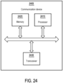
- FIG. 24 is a block diagram that illustrates a communication device according to an exemplary embodiment of the present disclosure.
- the communication device 2400 may be a UE or a network device.
- the communication device 2400 may include, but is not limited thereto a processor 2410.
- the processor 2410 (e.g., having processing circuitry) may include an intelligent hardware device, e.g., a Central Processing Unit (CPU), a microcontroller, an ASIC, etc.
- the processor 2410 can call and run a computer program from memory to implement the method in the embodiment of the disclosure.
- the program code stored in the communication device 2400 adopts all the technical solutions of all the foregoing embodiments when being executed by the processor 2410, it at least has all the advantageous effects brought by all the technical solutions of all the foregoing embodiments, and no further description is incorporated herein.
- the communication device 2400 may further include a memory 2420.
- the memory 2420 may include computer-storage media in the form of volatile and/or non-volatile memory.
- the memory 2420 may be removable, non-removable, or a combination thereof.
- Exemplary memory includes solid-state memory, hard drives, optical-disc drives, etc.
- the processor 2410 may call and run a computer program from the memory 2420 to implement the method in the embodiment of the disclosure.
- the memory 2420 may be a separate device independent of the processor 2410, or may be integrated in the processor 2410.
- the communication device 2400 may further include a transceiver 2430, and the processor 2410 may control the transceiver 2430 to communicate with other devices.
- the transceiver 2430 having a transmitter (e.g., transmitting/transmission circuitry) and a receiver (e.g., receiving/reception circuitry) may be configured to transmit and/or receive time and/or frequency resource partitioning information.
- the transceiver 2430 may be configured to transmit in different types of subframes and slots including, but not limited to, usable, non-usable and flexibly usable subframes and slot formats.
- the transceiver 2430 may be configured to receive data and control channels.
- the transceiver 2430 may send information or data to other devices, or receive information or data sent by other devices.
- the transceiver 2430 may include a transmitter and a receiver.
- the transceiver 2430 may further include an antenna, and the number of antennas may be one or more.
- the communication device 2400 may specifically be a network device in an embodiment of the disclosure, and the communication device 2400 may implement the corresponding process implemented by the network device in various methods of the embodiment of the disclosure. For the conciseness, related descriptions are omitted.
- the communication device 2400 may specifically be a mobile terminal, a terminal device, or a UE in an embodiment of the disclosure, and the communication device 2400 may implement the corresponding process implemented by the mobile terminal, the terminal device, or the UE in various methods in the embodiment of the disclosure. For conciseness, related description is omitted.
- a new type of DCI Field supporting of multi-panel operation for multi-cell scheduling is defined.
Landscapes
- Engineering & Computer Science (AREA)
- Signal Processing (AREA)
- Computer Networks & Wireless Communication (AREA)
- Mobile Radio Communication Systems (AREA)
Applications Claiming Priority (2)
| Application Number | Priority Date | Filing Date | Title |
|---|---|---|---|
| US202263411130P | 2022-09-29 | 2022-09-29 | |
| US18/469,559 US20240114523A1 (en) | 2022-09-29 | 2023-09-19 | Method for handling a multi-cell scheduling and user equipment |
Publications (1)
| Publication Number | Publication Date |
|---|---|
| EP4346309A1 true EP4346309A1 (fr) | 2024-04-03 |
Family
ID=88097834
Family Applications (1)
| Application Number | Title | Priority Date | Filing Date |
|---|---|---|---|
| EP23198596.1A Pending EP4346309A1 (fr) | 2022-09-29 | 2023-09-20 | Procédé de gestion d'une planification multicellulaire et équipement utilisateur |
Country Status (6)
| Country | Link |
|---|---|
| US (1) | US20240114523A1 (fr) |
| EP (1) | EP4346309A1 (fr) |
| JP (1) | JP7654736B2 (fr) |
| KR (1) | KR20240045117A (fr) |
| AU (1) | AU2023233134B2 (fr) |
| TW (1) | TWI871779B (fr) |
Families Citing this family (3)
| Publication number | Priority date | Publication date | Assignee | Title |
|---|---|---|---|---|
| US12641502B2 (en) * | 2023-01-20 | 2026-05-26 | Qualcomm Incorporated | Reference cell configuration |
| US20240284475A1 (en) * | 2023-02-16 | 2024-08-22 | Qualcomm Incorporated | Configuring uplink transmissions according to transmission configuration indicator state |
| KR20250160624A (ko) * | 2024-05-07 | 2025-11-14 | 삼성전자주식회사 | 통신 시스템에서 멀티 셀 스케줄링 방법 및 장치 |
Citations (2)
| Publication number | Priority date | Publication date | Assignee | Title |
|---|---|---|---|---|
| WO2021187966A1 (fr) * | 2020-03-18 | 2021-09-23 | 엘지전자 주식회사 | Procédé et dispositif de transmission/réception en liaison montante ou liaison descendante prenant en charge une planification multi-cellules dans un système de communication sans fil |
| WO2022047348A2 (fr) * | 2020-08-31 | 2022-03-03 | Yunjung Yi | Validation d'informations de commande de liaison descendante multi-cellule |
Family Cites Families (7)
| Publication number | Priority date | Publication date | Assignee | Title |
|---|---|---|---|---|
| US11159956B2 (en) * | 2019-03-28 | 2021-10-26 | Ofinno, Llc | Uplink beam management in wireless communication system |
| WO2021161272A1 (fr) * | 2020-02-13 | 2021-08-19 | Telefonaktiebolaget Lm Ericsson (Publ) | Améliorations de fiabilité pusch avec de multiples trps |
| KR102927643B1 (ko) * | 2020-03-31 | 2026-02-20 | 삼성전자주식회사 | 무선 통신 시스템에서 통신을 수행하는 방법 및 장치 |
| US12089203B2 (en) * | 2020-08-11 | 2024-09-10 | Samsung Electronics Co., Ltd. | Adaptive cross-carrier scheduling and flexible PUCCH groups |
| CN116458227B (zh) * | 2020-08-28 | 2025-05-13 | 株式会社Ntt都科摩 | 终端、无线通信方法、基站以及系统 |
| US12414126B2 (en) * | 2022-08-08 | 2025-09-09 | Qualcomm Incorporated | Scheduled cell identification for multi-cell scheduling |
| WO2024031696A1 (fr) * | 2022-08-12 | 2024-02-15 | 富士通株式会社 | Procédé de rapport d'informations d'état de canal et appareil |
-
2023
- 2023-09-19 US US18/469,559 patent/US20240114523A1/en active Pending
- 2023-09-20 EP EP23198596.1A patent/EP4346309A1/fr active Pending
- 2023-09-20 JP JP2023152080A patent/JP7654736B2/ja active Active
- 2023-09-21 AU AU2023233134A patent/AU2023233134B2/en active Active
- 2023-09-22 TW TW112136318A patent/TWI871779B/zh active
- 2023-09-22 KR KR1020230127445A patent/KR20240045117A/ko active Pending
Patent Citations (3)
| Publication number | Priority date | Publication date | Assignee | Title |
|---|---|---|---|---|
| WO2021187966A1 (fr) * | 2020-03-18 | 2021-09-23 | 엘지전자 주식회사 | Procédé et dispositif de transmission/réception en liaison montante ou liaison descendante prenant en charge une planification multi-cellules dans un système de communication sans fil |
| US20230134318A1 (en) * | 2020-03-18 | 2023-05-04 | Lg Electronics Inc. | Method and device for uplink or downlink transmission/reception supporting multi-cell scheduling in wireless communication system |
| WO2022047348A2 (fr) * | 2020-08-31 | 2022-03-03 | Yunjung Yi | Validation d'informations de commande de liaison descendante multi-cellule |
Non-Patent Citations (3)
| Title |
|---|
| APPLE INC: "On multi-cell PUSCH/PDSCH scheduling with a single DCI", vol. RAN WG1, no. Toulouse, France; 20220822 - 20220826, 12 August 2022 (2022-08-12), XP052275284, Retrieved from the Internet <URL:https://ftp.3gpp.org/tsg_ran/WG1_RL1/TSGR1_110/Docs/R1-2207349.zip R1-2207349 Apple_multi-cell scheduling DCI.docx> [retrieved on 20220812] * |
| HUAWEI ET AL: "Discussion on multi-cell scheduling with a single DCI", vol. RAN WG1, no. Toulouse, France; 20220822 - 20220826, 12 August 2022 (2022-08-12), XP052273792, Retrieved from the Internet <URL:https://ftp.3gpp.org/tsg_ran/WG1_RL1/TSGR1_110/Docs/R1-2205862.zip R1-2205862.docx> [retrieved on 20220812] * |
| SPREADTRUM COMMUNICATIONS: "Discussion on multi-cell PUSCH/PDSCH scheduling with a single DCI", vol. RAN WG1, no. Toulouse, France; 20220822 - 20220826, 20 August 2022 (2022-08-20), XP052275626, Retrieved from the Internet <URL:https://ftp.3gpp.org/tsg_ran/WG1_RL1/TSGR1_110/Docs/R1-2207695.zip R1-2207695.docx> [retrieved on 20220820] * |
Also Published As
| Publication number | Publication date |
|---|---|
| TW202415123A (zh) | 2024-04-01 |
| JP7654736B2 (ja) | 2025-04-01 |
| US20240114523A1 (en) | 2024-04-04 |
| TWI871779B (zh) | 2025-02-01 |
| JP2024050462A (ja) | 2024-04-10 |
| KR20240045117A (ko) | 2024-04-05 |
| AU2023233134B2 (en) | 2025-06-26 |
| AU2023233134A1 (en) | 2024-04-18 |
Similar Documents
| Publication | Publication Date | Title |
|---|---|---|
| US11929948B2 (en) | Method and apparatus for receiving or transmitting downlink signal in wireless communication system | |
| US11356224B2 (en) | Method and apparatus for receiving or transmitting downlink signal in wireless communication system | |
| CN110612765B (zh) | 在无线通信系统中发送上行链路信号的方法及其设备 | |
| KR101995434B1 (ko) | 무선 통신 시스템에서 상향링크 신호를 전송하기 위한 방법 및 이를 위한 장치 | |
| US10201007B2 (en) | Method for transreceiving signal and apparatus for same | |
| CN109952731B (zh) | 用于处理时间缩减的pucch资源分配和harq-ack报告的系统和方法 | |
| EP3270532B1 (fr) | Procédé de signalisation d'état de canal dans un système de communication sans fil et appareil associé | |
| CN107466451B (zh) | 用于发送干扰下行链路控制信息的方法及其装置 | |
| EP3480988A1 (fr) | Procédé de transmission en liaison montante dans un système de communication sans fil et dispositif associé | |
| CN105706381B (zh) | 用于发送信道质量指示符反馈的方法和用户设备 | |
| US20240114523A1 (en) | Method for handling a multi-cell scheduling and user equipment | |
| US10159090B2 (en) | Method for transmitting, to MTC device, PDSCH including downlink data, and base station therefor | |
| CN114430927A (zh) | 用于多个活动半持久调度配置的用户装备、基站和方法 | |
| CN105814827A (zh) | 从同时接入多小区的用户设备发送harq ack/nack 的方法 | |
| JP2017508343A (ja) | キャリアアグリゲーションためのシステムおよび方法 | |
| CN115004830A (zh) | 用于增强型混合自动重传请求过程的用户装备、基站和方法 | |
| CN119483842A (zh) | 生成混合自动重复请求harq码本的方法和装置 | |
| EP4266806A1 (fr) | Dispositif et procédé de gestion d'une planification multicellulaire | |
| EP3554159A1 (fr) | Procédé de prise en charge d'une pluralité d'intervalles de temps de transmission dans un système de communication sans fil, et appareil associé | |
| CN107852715B (zh) | 终端装置以及通信方法 | |
| US20250159696A1 (en) | Method and apparatus for receiving downlink control information in wireless communication system | |
| CN117793923A (zh) | 处理多小区调度的方法和用户设备 | |
| KR20220104544A (ko) | 통신 시스템에서 멀티캐스팅 및 브로드캐스팅을 제공하는 방법 및 장치 | |
| KR20250125746A (ko) | 네트워크 협력통신에서 상향링크 전송 방법 및 장치 | |
| KR20240150288A (ko) | 무선 통신 시스템에 있어서 상향링크 제어 채널을 전송하기 위한 방법 및 장치 |
Legal Events
| Date | Code | Title | Description |
|---|---|---|---|
| PUAI | Public reference made under article 153(3) epc to a published international application that has entered the european phase |
Free format text: ORIGINAL CODE: 0009012 |
|
| STAA | Information on the status of an ep patent application or granted ep patent |
Free format text: STATUS: THE APPLICATION HAS BEEN PUBLISHED |
|
| AK | Designated contracting states |
Kind code of ref document: A1 Designated state(s): AL AT BE BG CH CY CZ DE DK EE ES FI FR GB GR HR HU IE IS IT LI LT LU LV MC ME MK MT NL NO PL PT RO RS SE SI SK SM TR |
|
| STAA | Information on the status of an ep patent application or granted ep patent |
Free format text: STATUS: REQUEST FOR EXAMINATION WAS MADE |
|
| 17P | Request for examination filed |
Effective date: 20240726 |
|
| RBV | Designated contracting states (corrected) |
Designated state(s): AL AT BE BG CH CY CZ DE DK EE ES FI FR GB GR HR HU IE IS IT LI LT LU LV MC ME MK MT NL NO PL PT RO RS SE SI SK SM TR |