EP4345986A2 - Vehicle battery cooling apparatus - Google Patents
Vehicle battery cooling apparatus Download PDFInfo
- Publication number
- EP4345986A2 EP4345986A2 EP23196189.7A EP23196189A EP4345986A2 EP 4345986 A2 EP4345986 A2 EP 4345986A2 EP 23196189 A EP23196189 A EP 23196189A EP 4345986 A2 EP4345986 A2 EP 4345986A2
- Authority
- EP
- European Patent Office
- Prior art keywords
- heat transfer
- transfer medium
- press
- medium flow
- flat surface
- Prior art date
- Legal status (The legal status is an assumption and is not a legal conclusion. Google has not performed a legal analysis and makes no representation as to the accuracy of the status listed.)
- Pending
Links
Images




Classifications
-
- H—ELECTRICITY
- H01—ELECTRIC ELEMENTS
- H01M—PROCESSES OR MEANS, e.g. BATTERIES, FOR THE DIRECT CONVERSION OF CHEMICAL ENERGY INTO ELECTRICAL ENERGY
- H01M10/00—Secondary cells; Manufacture thereof
- H01M10/60—Heating or cooling; Temperature control
- H01M10/61—Types of temperature control
- H01M10/613—Cooling or keeping cold
-
- H—ELECTRICITY
- H01—ELECTRIC ELEMENTS
- H01M—PROCESSES OR MEANS, e.g. BATTERIES, FOR THE DIRECT CONVERSION OF CHEMICAL ENERGY INTO ELECTRICAL ENERGY
- H01M10/00—Secondary cells; Manufacture thereof
- H01M10/60—Heating or cooling; Temperature control
- H01M10/62—Heating or cooling; Temperature control specially adapted for specific applications
- H01M10/625—Vehicles
-
- H—ELECTRICITY
- H01—ELECTRIC ELEMENTS
- H01M—PROCESSES OR MEANS, e.g. BATTERIES, FOR THE DIRECT CONVERSION OF CHEMICAL ENERGY INTO ELECTRICAL ENERGY
- H01M10/00—Secondary cells; Manufacture thereof
- H01M10/60—Heating or cooling; Temperature control
- H01M10/64—Heating or cooling; Temperature control characterised by the shape of the cells
- H01M10/647—Prismatic or flat cells, e.g. pouch cells
-
- H—ELECTRICITY
- H01—ELECTRIC ELEMENTS
- H01M—PROCESSES OR MEANS, e.g. BATTERIES, FOR THE DIRECT CONVERSION OF CHEMICAL ENERGY INTO ELECTRICAL ENERGY
- H01M10/00—Secondary cells; Manufacture thereof
- H01M10/60—Heating or cooling; Temperature control
- H01M10/65—Means for temperature control structurally associated with the cells
- H01M10/655—Solid structures for heat exchange or heat conduction
- H01M10/6554—Rods or plates
-
- H—ELECTRICITY
- H01—ELECTRIC ELEMENTS
- H01M—PROCESSES OR MEANS, e.g. BATTERIES, FOR THE DIRECT CONVERSION OF CHEMICAL ENERGY INTO ELECTRICAL ENERGY
- H01M10/00—Secondary cells; Manufacture thereof
- H01M10/60—Heating or cooling; Temperature control
- H01M10/65—Means for temperature control structurally associated with the cells
- H01M10/655—Solid structures for heat exchange or heat conduction
- H01M10/6556—Solid parts with flow channel passages or pipes for heat exchange
-
- H—ELECTRICITY
- H01—ELECTRIC ELEMENTS
- H01M—PROCESSES OR MEANS, e.g. BATTERIES, FOR THE DIRECT CONVERSION OF CHEMICAL ENERGY INTO ELECTRICAL ENERGY
- H01M10/00—Secondary cells; Manufacture thereof
- H01M10/60—Heating or cooling; Temperature control
- H01M10/65—Means for temperature control structurally associated with the cells
- H01M10/656—Means for temperature control structurally associated with the cells characterised by the type of heat-exchange fluid
- H01M10/6567—Liquids
- H01M10/6568—Liquids characterised by flow circuits, e.g. loops, located externally to the cells or cell casings
-
- H—ELECTRICITY
- H01—ELECTRIC ELEMENTS
- H01M—PROCESSES OR MEANS, e.g. BATTERIES, FOR THE DIRECT CONVERSION OF CHEMICAL ENERGY INTO ELECTRICAL ENERGY
- H01M50/00—Constructional details or processes of manufacture of the non-active parts of electrochemical cells other than fuel cells, e.g. hybrid cells
- H01M50/20—Mountings; Secondary casings or frames; Racks, modules or packs; Suspension devices; Shock absorbers; Transport or carrying devices; Holders
- H01M50/204—Racks, modules or packs for multiple batteries or multiple cells
-
- H—ELECTRICITY
- H01—ELECTRIC ELEMENTS
- H01M—PROCESSES OR MEANS, e.g. BATTERIES, FOR THE DIRECT CONVERSION OF CHEMICAL ENERGY INTO ELECTRICAL ENERGY
- H01M50/00—Constructional details or processes of manufacture of the non-active parts of electrochemical cells other than fuel cells, e.g. hybrid cells
- H01M50/20—Mountings; Secondary casings or frames; Racks, modules or packs; Suspension devices; Shock absorbers; Transport or carrying devices; Holders
- H01M50/262—Mountings; Secondary casings or frames; Racks, modules or packs; Suspension devices; Shock absorbers; Transport or carrying devices; Holders with fastening means, e.g. locks
- H01M50/264—Mountings; Secondary casings or frames; Racks, modules or packs; Suspension devices; Shock absorbers; Transport or carrying devices; Holders with fastening means, e.g. locks for cells or batteries, e.g. straps, tie rods or peripheral frames
-
- H—ELECTRICITY
- H01—ELECTRIC ELEMENTS
- H01M—PROCESSES OR MEANS, e.g. BATTERIES, FOR THE DIRECT CONVERSION OF CHEMICAL ENERGY INTO ELECTRICAL ENERGY
- H01M50/00—Constructional details or processes of manufacture of the non-active parts of electrochemical cells other than fuel cells, e.g. hybrid cells
- H01M50/20—Mountings; Secondary casings or frames; Racks, modules or packs; Suspension devices; Shock absorbers; Transport or carrying devices; Holders
- H01M50/289—Mountings; Secondary casings or frames; Racks, modules or packs; Suspension devices; Shock absorbers; Transport or carrying devices; Holders characterised by spacing elements or positioning means within frames, racks or packs
- H01M50/291—Mountings; Secondary casings or frames; Racks, modules or packs; Suspension devices; Shock absorbers; Transport or carrying devices; Holders characterised by spacing elements or positioning means within frames, racks or packs characterised by their shape
-
- Y—GENERAL TAGGING OF NEW TECHNOLOGICAL DEVELOPMENTS; GENERAL TAGGING OF CROSS-SECTIONAL TECHNOLOGIES SPANNING OVER SEVERAL SECTIONS OF THE IPC; TECHNICAL SUBJECTS COVERED BY FORMER USPC CROSS-REFERENCE ART COLLECTIONS [XRACs] AND DIGESTS
- Y02—TECHNOLOGIES OR APPLICATIONS FOR MITIGATION OR ADAPTATION AGAINST CLIMATE CHANGE
- Y02E—REDUCTION OF GREENHOUSE GAS [GHG] EMISSIONS, RELATED TO ENERGY GENERATION, TRANSMISSION OR DISTRIBUTION
- Y02E60/00—Enabling technologies; Technologies with a potential or indirect contribution to GHG emissions mitigation
- Y02E60/10—Energy storage using batteries
Definitions
- the present invention relates to a vehicle battery cooling apparatus capable of cooling a battery by exchanging heat with a heat transfer medium.
- Patent Literature 1 An existing technique related to the vehicle battery cooling apparatus is disclosed in Patent Literature 1.
- the vehicle battery cooling apparatus disclosed in Patent Literature 1 includes: a flat heat exchanger through which a heat transfer medium flows; a press member which is capable of pressing the heat exchanger against a lower surface of a battery; and a case which houses the press member.
- the press member includes: a press main body member which has a press flat surface in contact with a lower surface of the heat exchanger; and a leaf spring which is disposed between the press main body member and the case. The force generated by this leaf spring enables the heat exchanger to be pressed against the battery reliably.
- a heat exchanger of Patent Literature 2 can be employed as the heat exchanger of the cooling apparatus.
- the heat exchanger of Patent Literature 2 includes a first heat transfer medium flow path and a second heat transfer medium flow path whose heights are different from each other. The height of the second heat transfer medium flow path is lower than that of the first heat transfer medium flow path.
- the present invention aims to provide a vehicle battery cooling apparatus having a high cooling performance.
- the present invention provides a vehicle battery cooling apparatus (11) including:
- the present invention can provide a vehicle battery cooling apparatus having a high cooling performance.
- Up indicates an upper side and Dn indicates a lower side.
- Fig. 1 illustrates: a battery 10 (vehicle battery 10) that accumulates electricity; and a cooling apparatus 11 (vehicle battery cooling apparatus) that is capable of cooling the battery 10.
- the battery 10 and the cooling apparatus 11 are mounted, for example, in an electric vehicle which travels by driving a travel motor using power, and a hybrid vehicle whose power source consists of an internal combustion engine and a motor.
- the battery 10 is used for energizing a motor for traveling of a vehicle, and generates heat and increases in temperature during charging. Between the battery 10 and the cooling apparatus 11, a close contact member 12 is provided to cause the cooling apparatus 11 to come into close contact with a lower surface 10a of the battery 10.
- the close contact member 12 is made of an elastic material. The battery 10 and the cooling apparatus 11 exchange heat via the close contact member 12.
- the cooling apparatus 11 of the first embodiment includes: a heat exchanger 20 that is capable of cooling the battery 10; and two press members 30 that are capable of pressing the heat exchanger 20 against the close contact member 12 attached to the lower surface 10a of the battery 10.
- the press members 30 are housed at least inside a battery case 40 mounted on the vehicle.
- the press members 30 can press the heat exchanger 20 against the battery 10 using the battery 10's own weight.
- the cooling apparatus 11 may be attached to an upper surface or a side surface of the battery 10.
- known attachment structures such as a structure of fixing the battery case 40 to the battery 10 may be used.
- the heat exchanger 20 is made in such a way that a first plate member 21 located on the battery 10 side (upper side) and a second plate member 25 located on the press member 30 side (lower side) overlap with each other.
- the first plate member 21 is in the form of a flat plate as a whole.
- the first plate member 21 has a cooling flat surface 22 that is capable of coming into contact with the close contact member 12 (see Fig. 2 ).
- the cooling flat surface 22 is capable of being thermally coupled to the battery 10.
- the first plate member is preferably made using an aluminum alloy or copper. Concave-convex portions (not illustrated) may be formed in the first plate member 21 by press machining as long as the first plate member 21 has the cooling flat surface 22 and can be joined to the second plate member 25.
- the second plate member 25 is a molded part formed by press machining.
- the second plate member 25 is made in such a way that multiple joint portions 26 joined to the first plate member 21 and multiple semi-cylindrical protrusion portions 28, 29 protruding toward the press members 30 than the joint portions 26 are formed in one unit.
- the direction in which the protrusion portions 28, 29 protrude can also be said as a direction along the direction in which the press members 30 press.
- the second plate member is preferably made using an aluminum alloy or copper.
- the protrusion portions 28, 29 of the second plate member 25 and the first plate member 21 constitute multiple heat transfer medium flow paths 51, 52 through which a heat transfer medium can flow.
- a cooling water made by being cooled by a chiller (not illustrated), and a gas-liquid mixed refrigerant made by being thermally insulated and expanded are used.
- the joint portions 26 of the second plate member 25 each have an opposed surface 27 that is opposed to the press member 30.
- the dimensions of the protrusion portions 28, 29 based on this opposed surface 27 are set as dimensions L1, L2 of the heat transfer medium flow paths.
- the multiple heat transfer medium flow paths 51, 52 include first heat transfer medium flow paths 51 and second heat transfer medium flow paths 52 whose dimensions are different from each other.
- the dimension L2 of each second heat transfer medium flow path 52 (the dimension from the opposed surface 27 to a tip 28a of the second protrusion portion 28 in the press direction) is smaller than the dimension L1 of each first heat transfer medium flow path 51 (the dimension from the opposed surface 27 to a tip 29a of the first protrusion portion 29 in the press direction).
- the cross-sectional shape of the second heat transfer medium flow path 52 is more flattened than that of the first heat transfer medium flow path 51.
- the heat transfer medium flow path's equivalent diameter (hydraulic diameter) of the second heat transfer medium flow path 52 relatively smaller, it is possible to enhance the heat exchange efficiency.
- the cross-sectional area of the second heat transfer medium flow path 52 smaller than that of the first heat transfer medium flow path 51 to make the flow velocity of the heat transfer medium relatively faster, it is possible to help mixing of the heat transfer medium flowing through the second heat transfer medium flow path 52 and thus enhance the heat exchange efficiency.
- the second heat transfer medium flow path 52 in the heat exchanger 20, it is possible to enhance the cooling performance for a predetermined region of the battery 10.
- Each press member 30 includes a press flat surface 31 that is capable of pressing the heat exchanger 20 against the battery 10 when the cooling apparatus 11 is attached to the battery 10 (hereinafter referred to as "during attachment").
- the press flat surface 31 is set large enough to cover the entire surface of the heat exchanger 20 on the heat transfer medium flow paths 51, 52 side thereof.
- the whole shape of the press member 30 is not limited to a plate shape as long as the press member has this press flat surface 31.
- the cooling apparatus 11 of the first embodiment includes no leaf spring 70 to be described later, and thus a surface 34 opposite from the press flat surface 31 can be directly in contact with the battery case 40 during attachment.
- the press flat surface 31 is in contact with a part of the heat transfer medium flow paths 51, 52. Specifically, during attachment, the press flat surface 31 is in contact with the first heat transfer medium flow paths 51. The press flat surface 31 is not in contact with the tips of the second heat transfer medium flow paths 52. Note that, in Fig. 1 , the press flat surface 31 is constituted of: a solid line portion that is in contact with the first heat transfer medium flow paths 51; and a virtual dotted line portion that is located on the same plane as this solid line portion and described in a boundary portion with an intervening member 60 to be described later.
- a gap generated during attachment between the second heat transfer medium flow paths 52 and the press flat surface 31 is set as a gap region S.
- the intervening member 60 is disposed in the gap region S.
- the intervening member 60 is formed as an integrated unit with the press member 30.
- the intervening member 60 and the press member 30 are made of an elastic material.
- the elastic material is urethane foam, for example.
- the intervening member 60 has a first contact flat surface 61 that is in contact with the second heat transfer medium flow paths 52 (the tips 28a of the second protrusion portions 28) during attachment.
- the press flat surface 31 presses the second heat transfer medium flow paths 52 against the battery 10 via the first contact flat surface 61 of the intervening member 60.
- the press flat surface 31 directly presses the first heat transfer medium flow paths 51 against the battery 10.
- a plane that is parallel to the cooling flat surface 22 and includes the tips of the first heat transfer medium flow paths 51 (the tips 29a of the first protrusion portions 29) is set as a first plane P1.
- a plane that is parallel to the cooling flat surface 22 and includes the tips of the second heat transfer medium flow paths 52 (the tips 28a of the second protrusion portions 28) is set as a second plane P2.
- a clearance between the first plane P1 and the second plane P2 (a clearance between the tip of each first heat transfer medium flow path 51 and the tip of each second heat transfer medium flow path 52) generated before the cooling apparatus 11 is attached to the battery 10 (hereinafter referred to as "before attachment") is set as a clearance C.
- the clearance C can also be said as the height of the gap region S.
- the first plane P1 is a plane that includes the press flat surface 31 during attachment.
- the second plane P2 is a plane that includes the first contact flat surface 61 during attachment.
- a thickness T of the intervening member 60 is set slightly larger than the clearance C (T>C).
- the thickness T of the intervening member 60 can be changed as appropriate as long as the first contact flat surface 61 of the intervening member 60 is in contact with the second heat transfer medium flow paths 52 and the press flat surface 31 is in contact with the first heat transfer medium flow paths 51 during attachment.
- the gap region S can also be said as a space that is formed in a concave shape out of portions of the heat exchanger 20 on the press member 30 side thereof.
- the position where the gap region S is formed and the number of the gap region S can be changed as appropriate.
- the outer shape of the heat exchanger 20 is not limited to that of the first embodiment as long as the heat exchanger includes the cooling flat surface 22 and has such a shape that the gap region S is formed by the first plane P1 and the second plane P2 formed to have a difference of elevation.
- the cooling apparatus 11 includes the first heat transfer medium flow paths 51 and the second heat transfer medium flow paths 52 having the different dimensions L1, L2 from each other, and thus the gap region S is formed in the cooling apparatus 11.
- the intervening member 60 is disposed in the gap region S.
- This intervening member 60 has the first contact flat surface 61 that is capable of coming into contact with the second heat transfer medium flow paths 52.
- the press member 30 has the press flat surface 31 that is capable of coming into contact with the tips of the first heat transfer medium flow paths 51.
- the press member 30 can directly press the first heat transfer medium flow paths 51 against the battery 10 and, at the same time, can press the second heat transfer medium flow paths 52 against the battery 10 via the intervening member 60.
- This can enhance the cooling performance of the cooling apparatus 11. Since the second heat transfer medium flow paths 52 having a higher cooling capability than the first heat transfer medium flow paths 51 can be pressed against the battery 10, it is possible to enhance the cooling performance of the cooling apparatus 11. Further, by providing the second heat transfer medium flow paths 52 to be corresponding to the region with an especially large amount of heat in the battery 10, it is possible to effectively suppress deterioration of the battery 10 due to heat.
- the thickness T of the intervening member 60 is set slightly larger than the clearance C (T>C). This enables the press member 30 to press the second heat transfer medium flow paths 52 more reliably. This can further enhance the cooling performance of the heat exchanger 20.
- the intervening member 60 is formed as an integrated unit with the press member 30. This can decrease the number of components constituting the cooling apparatus 11.
- the intervening member 60 and the press member 30 are made of an elastic material. During attachment, the intervening member 60 and the press member 30 are compressed. Since the press member 30 formed as an integrated unit with the intervening member 60 are made of an elastic material, many points where a force is applied during attachment are formed, so that it enables to press the heat exchanger 20 against the battery 10 more reliably.
- Fig. 5 illustrates a state where a cooling apparatus 11A according to a second embodiment is attached to the battery 10.
- the same reference numerals as those of the first embodiment are given and their description will be omitted.
- a press member 30A includes: a press main body member 32 that has a press flat surface 31A; and the leaf spring 70 that is capable of pressing the press main body member 32 against the heat exchanger 20.
- the leaf spring 70 has a curved shape in cross section such that it bulges toward the press main body member 32 (to the upper side).
- the material of the leaf spring 70 is not particularly limited as long as it can press the press main body member 32, and a metallic material such as a stainless material may be used. Note that, although not illustrated in the drawing, the leaf spring 70 is supported by the battery case 40 (see Fig. 1 ).
- a range in contact with the second heat transfer medium flow paths 52 is set as a contact range 61Aa.
- a surface opposite from the press flat surface 31A is set as an opposite flat surface 33.
- a range corresponding to the contact range 61Aa is set as a corresponding range 33a.
- An apex portion 71 of the leaf spring 70 is located in the corresponding range 33a of the opposite flat surface 33. This enables the press member 30A to press the second heat transfer medium flow paths 52 via the intervening member 60A more reliably.
- the press main body member 32 and the intervening member 60A are formed in one unit.
- the press main body member 32 and the intervening member 60A are preferably made of a resin material having a predetermined strength.
- a resin material having a predetermined strength for example, polypropylene is used as the resin material.
- Fig. 6 illustrates a cooling apparatus 11B according to a third embodiment.
- the same reference numerals as those of the second embodiment are given and their description will be omitted.
- a press main body member 32B and an intervening member 60B are separate bodies. Both the press main body member 32B and the intervening member 60B are plate-shaped and preferably made of a resin material having a predetermined strength.
- the press main body member 32B may be made of a resin material having a predetermined strength (such as polypropylene), and the intervening member 60B may be made of a foamed material (such as urethane foam).
- the press main body member 32B having a predetermined strength can receive a force by which the apex portion 71 of the leaf spring 70 presses, and the intervening member 60B made of a foamed material can transmit the press force thus received to the multiple second heat transfer medium flow paths 52 in a distributed manner.
- a resin material having a predetermined strength such as polypropylene
- the intervening member 60B may be made of a foamed material (such as urethane foam).
- the intervening member 60B includes: a first contact flat surface 61B that is in contact with the second heat transfer medium flow paths 52 during attachment; and a second contact flat surface 62B that is in contact with a press flat surface 31B of the press main body member 32B during attachment.
- Fig. 7 illustrates a cooling apparatus 11C according to a fourth embodiment.
- the same reference numerals as those of the third embodiment are given and their description will be omitted.
- An intervening member 60C is made of aluminum.
- the shape and size of the intervening member 60C are the same as those of the intervening member 60B of the third embodiment.
- the joint portions 26 of the first plate member 21 and the second plate member 25 are joined by brazing.
- a first contact flat surface 61C of the intervening member 60C and the second heat transfer medium flow paths 52 (the tips 28a of the second protrusion portions 28) are joined by brazing.
- the present invention is not limited to the first to fourth embodiments as long as the operations and effects of the present invention are exhibited.
- the vehicle battery cooling apparatus according to the present invention is suitable for being mounted on a passenger vehicle.
Landscapes
- Chemical & Material Sciences (AREA)
- Chemical Kinetics & Catalysis (AREA)
- Electrochemistry (AREA)
- General Chemical & Material Sciences (AREA)
- Engineering & Computer Science (AREA)
- Manufacturing & Machinery (AREA)
- Cooling, Air Intake And Gas Exhaust, And Fuel Tank Arrangements In Propulsion Units (AREA)
- Secondary Cells (AREA)
Abstract
Description
- The present invention relates to a vehicle battery cooling apparatus capable of cooling a battery by exchanging heat with a heat transfer medium.
- In an electric vehicle which travels by driving a travel motor using power, and a hybrid vehicle whose power source consists of an internal combustion engine and a motor, a battery that accumulates electricity and a vehicle battery cooling apparatus that is capable of cooling the battery are mounted. An existing technique related to the vehicle battery cooling apparatus is disclosed in Patent Literature 1.
- The vehicle battery cooling apparatus disclosed in Patent Literature 1 includes: a flat heat exchanger through which a heat transfer medium flows; a press member which is capable of pressing the heat exchanger against a lower surface of a battery; and a case which houses the press member.
- The press member includes: a press main body member which has a press flat surface in contact with a lower surface of the heat exchanger; and a leaf spring which is disposed between the press main body member and the case. The force generated by this leaf spring enables the heat exchanger to be pressed against the battery reliably.
- For example, a heat exchanger of
Patent Literature 2 can be employed as the heat exchanger of the cooling apparatus. The heat exchanger ofPatent Literature 2 includes a first heat transfer medium flow path and a second heat transfer medium flow path whose heights are different from each other. The height of the second heat transfer medium flow path is lower than that of the first heat transfer medium flow path. - Patent Literature 1:
US2015/0044540A - Patent Literature 2:
JPH06-246365A - In the case of employing the heat exchanger of
Patent Literature 2 in the cooling apparatus, when the cooling apparatus is attached to the battery, a gap is formed between the press member and the second heat transfer medium flow path having a low height. In other words, since the press member is not in contact with the second heat transfer medium flow path of the heat exchanger, the press member is unable to press a surface opposite from the second heat transfer medium flow path against the battery, thus deteriorating the cooling performance. - The present invention aims to provide a vehicle battery cooling apparatus having a high cooling performance.
- In the following description, reference numerals in the accompanying drawings are appended in parentheses to facilitate understanding of the present invention, but the present invention is not limited to illustrated embodiments.
- The present invention provides a vehicle battery cooling apparatus (11) including:
- a heat exchanger (20) that includes a cooling flat surface (22) which is capable of being thermally coupled to a vehicle battery (10) and multiple heat transfer medium flow paths (51, 52) which are formed to protrude opposite from the cooling flat surface (22) and through which a heat transfer medium flows; and
- a press member (30) that is capable of pressing the heat exchanger (20) against the vehicle battery (10) and has a press flat surface (31, 31A, 31B) which is in contact with a part of the multiple heat transfer medium flow paths (51, 52) and presses the part of the multiple heat transfer medium flow paths (51, 52) against the vehicle battery (10), in which
- the multiple heat transfer medium flow paths (51, 52) include a first heat transfer medium flow path (51) whose dimension is relatively large and which is in contact with the press flat surface (31, 31A, 31B) and a second heat transfer medium flow path (52) whose dimension is smaller than the first heat transfer medium flow path (51) and which is not in contact with the press flat surface (31, 31A, 31B) based on a direction along a direction in which the press member (30) presses,
- an intervening member (60, 60A, 60B, 60C) that is capable of coming into contact with the second heat transfer medium flow path (52) and, at the same time, capable of coming into contact with the press flat surface (31, 31A, 31B) is disposed in a gap region (S) between the second heat transfer medium flow path (52) and the press flat surface (31, 31A, 31B), and
- the press flat surface (31, 31A, 31B) is capable of directly pressing the first heat transfer medium flow path (51) against the vehicle battery (10) and, at the same time, capable of pressing the second heat transfer medium flow path (52) against the vehicle battery (10) via the intervening member (60, 60A, 60B, 60C).
- The present invention can provide a vehicle battery cooling apparatus having a high cooling performance.
-
-
Fig. 1 is a diagram schematically illustrating a cross-section of a vehicle battery cooling apparatus of a first embodiment attached to a vehicle battery. -
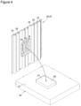
Fig. 2 is a schematic perspective diagram of the vehicle battery cooling apparatus illustrated inFig. 1 . -
Fig. 3 is a diagram illustrating dimensions of a heat exchanger and a press member prior to attachment to the vehicle battery. -
Fig. 4 is a diagram illustrating a gap space formed in the heat exchanger and an intervening member disposed in the gap space. -
Fig. 5 is a diagram schematically illustrating a cross-section of a vehicle battery cooling apparatus of a second embodiment attached to the vehicle battery. -
Fig. 6 is a diagram schematically illustrating a cross-section of a vehicle battery cooling apparatus of a third embodiment attached to the vehicle battery. -
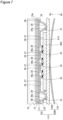
Fig. 7 is a diagram schematically illustrating a cross-section of a vehicle battery cooling apparatus of a fourth embodiment attached to the vehicle battery. - Embodiments will be described below with reference to the accompanying drawings. In the drawings, Up indicates an upper side and Dn indicates a lower side.
-
Fig. 1 illustrates: a battery 10 (vehicle battery 10) that accumulates electricity; and a cooling apparatus 11 (vehicle battery cooling apparatus) that is capable of cooling thebattery 10. Thebattery 10 and thecooling apparatus 11 are mounted, for example, in an electric vehicle which travels by driving a travel motor using power, and a hybrid vehicle whose power source consists of an internal combustion engine and a motor. - Reference is made to
Figs. 1 and2 . Thebattery 10 is used for energizing a motor for traveling of a vehicle, and generates heat and increases in temperature during charging. Between thebattery 10 and thecooling apparatus 11, aclose contact member 12 is provided to cause thecooling apparatus 11 to come into close contact with alower surface 10a of thebattery 10. Theclose contact member 12 is made of an elastic material. Thebattery 10 and thecooling apparatus 11 exchange heat via theclose contact member 12. - The
cooling apparatus 11 of the first embodiment includes: aheat exchanger 20 that is capable of cooling thebattery 10; and twopress members 30 that are capable of pressing theheat exchanger 20 against theclose contact member 12 attached to thelower surface 10a of thebattery 10. Thepress members 30 are housed at least inside abattery case 40 mounted on the vehicle. - Note that, when the
cooling apparatus 11 is attached to thelower surface 10a of thebattery 10, thepress members 30 can press theheat exchanger 20 against thebattery 10 using thebattery 10's own weight. Thecooling apparatus 11 may be attached to an upper surface or a side surface of thebattery 10. In the case of attaching thecooling apparatus 11 to the upper surface or the side surface of thebattery 10, known attachment structures such as a structure of fixing thebattery case 40 to thebattery 10 may be used. - Reference is made to
Fig. 3 . Theheat exchanger 20 is made in such a way that afirst plate member 21 located on thebattery 10 side (upper side) and asecond plate member 25 located on thepress member 30 side (lower side) overlap with each other. - Portions where these members overlap with each other are joined (welded or brazed, for example).
- The
first plate member 21 is in the form of a flat plate as a whole. Thefirst plate member 21 has a coolingflat surface 22 that is capable of coming into contact with the close contact member 12 (seeFig. 2 ). The coolingflat surface 22 is capable of being thermally coupled to thebattery 10. In order to join thefirst plate member 21 to thesecond plate member 25 by welding or brazing, the first plate member is preferably made using an aluminum alloy or copper. Concave-convex portions (not illustrated) may be formed in thefirst plate member 21 by press machining as long as thefirst plate member 21 has the coolingflat surface 22 and can be joined to thesecond plate member 25. - The
second plate member 25 is a molded part formed by press machining. Thesecond plate member 25 is made in such a way that multiplejoint portions 26 joined to thefirst plate member 21 and multiplesemi-cylindrical protrusion portions press members 30 than thejoint portions 26 are formed in one unit. The direction in which theprotrusion portions press members 30 press. In order to join thesecond plate member 25 to thefirst plate member 21 by welding or brazing, the second plate member is preferably made using an aluminum alloy or copper. - Out of the
multiple protrusion portions first protrusion portions 29, and ones that protrude smaller than thefirst protrusion portions 29 are set assecond protrusion portions 28. Theprotrusion portions second plate member 25 and thefirst plate member 21 constitute multiple heat transfermedium flow paths - The
joint portions 26 of thesecond plate member 25 each have an opposedsurface 27 that is opposed to thepress member 30. The dimensions of theprotrusion portions opposed surface 27 are set as dimensions L1, L2 of the heat transfer medium flow paths. The multiple heat transfermedium flow paths medium flow paths 51 and second heat transfermedium flow paths 52 whose dimensions are different from each other. The dimension L2 of each second heat transfer medium flow path 52 (the dimension from the opposedsurface 27 to atip 28a of thesecond protrusion portion 28 in the press direction) is smaller than the dimension L1 of each first heat transfer medium flow path 51 (the dimension from the opposedsurface 27 to atip 29a of thefirst protrusion portion 29 in the press direction). The cross-sectional shape of the second heat transfermedium flow path 52 is more flattened than that of the first heat transfermedium flow path 51. By making the heat transfer medium flow path's equivalent diameter (hydraulic diameter) of the second heat transfermedium flow path 52 relatively smaller, it is possible to enhance the heat exchange efficiency. Alternatively, by making the cross-sectional area of the second heat transfermedium flow path 52 smaller than that of the first heat transfermedium flow path 51 to make the flow velocity of the heat transfer medium relatively faster, it is possible to help mixing of the heat transfer medium flowing through the second heat transfermedium flow path 52 and thus enhance the heat exchange efficiency. In other words, by providing the second heat transfermedium flow path 52 in theheat exchanger 20, it is possible to enhance the cooling performance for a predetermined region of thebattery 10. - Reference is made to
Figs. 1 and2 . Eachpress member 30 includes a pressflat surface 31 that is capable of pressing theheat exchanger 20 against thebattery 10 when thecooling apparatus 11 is attached to the battery 10 (hereinafter referred to as "during attachment"). The pressflat surface 31 is set large enough to cover the entire surface of theheat exchanger 20 on the heat transfermedium flow paths press member 30 is not limited to a plate shape as long as the press member has this pressflat surface 31. - Note that, the
cooling apparatus 11 of the first embodiment includes noleaf spring 70 to be described later, and thus asurface 34 opposite from the pressflat surface 31 can be directly in contact with thebattery case 40 during attachment. - As illustrated in
Fig. 1 , during attachment, the pressflat surface 31 is in contact with a part of the heat transfermedium flow paths flat surface 31 is in contact with the first heat transfermedium flow paths 51. The pressflat surface 31 is not in contact with the tips of the second heat transfermedium flow paths 52. Note that, inFig. 1 , the pressflat surface 31 is constituted of: a solid line portion that is in contact with the first heat transfermedium flow paths 51; and a virtual dotted line portion that is located on the same plane as this solid line portion and described in a boundary portion with an interveningmember 60 to be described later. - A gap generated during attachment between the second heat transfer
medium flow paths 52 and the pressflat surface 31 is set as a gap region S. - The intervening
member 60 is disposed in the gap region S. The interveningmember 60 is formed as an integrated unit with thepress member 30. The interveningmember 60 and thepress member 30 are made of an elastic material. The elastic material is urethane foam, for example. - The intervening
member 60 has a first contactflat surface 61 that is in contact with the second heat transfer medium flow paths 52 (thetips 28a of the second protrusion portions 28) during attachment. In other words, during attachment, the pressflat surface 31 presses the second heat transfermedium flow paths 52 against thebattery 10 via the first contactflat surface 61 of the interveningmember 60. The pressflat surface 31 directly presses the first heat transfermedium flow paths 51 against thebattery 10. - Reference is made to
Fig. 3 . A plane that is parallel to the coolingflat surface 22 and includes the tips of the first heat transfer medium flow paths 51 (thetips 29a of the first protrusion portions 29) is set as a first plane P1. A plane that is parallel to the coolingflat surface 22 and includes the tips of the second heat transfer medium flow paths 52 (thetips 28a of the second protrusion portions 28) is set as a second plane P2. A clearance between the first plane P1 and the second plane P2 (a clearance between the tip of each first heat transfermedium flow path 51 and the tip of each second heat transfer medium flow path 52) generated before thecooling apparatus 11 is attached to the battery 10 (hereinafter referred to as "before attachment") is set as a clearance C. - Note that, the clearance C can also be said as the height of the gap region S. The first plane P1 is a plane that includes the press
flat surface 31 during attachment. The second plane P2 is a plane that includes the first contactflat surface 61 during attachment. - A thickness T of the intervening
member 60 is set slightly larger than the clearance C (T>C). However, the thickness T of the interveningmember 60 can be changed as appropriate as long as the first contactflat surface 61 of the interveningmember 60 is in contact with the second heat transfermedium flow paths 52 and the pressflat surface 31 is in contact with the first heat transfermedium flow paths 51 during attachment. - Reference is made to
Figs. 2 to 4 . The gap region S can also be said as a space that is formed in a concave shape out of portions of theheat exchanger 20 on thepress member 30 side thereof. The position where the gap region S is formed and the number of the gap region S can be changed as appropriate. Further, the outer shape of theheat exchanger 20 is not limited to that of the first embodiment as long as the heat exchanger includes the coolingflat surface 22 and has such a shape that the gap region S is formed by the first plane P1 and the second plane P2 formed to have a difference of elevation. - Reference is made to
Fig. 3 . Thecooling apparatus 11 includes the first heat transfermedium flow paths 51 and the second heat transfermedium flow paths 52 having the different dimensions L1, L2 from each other, and thus the gap region S is formed in thecooling apparatus 11. - Reference is made to
Fig. 1 . The configuration of thecooling apparatus 11 during attachment will be described. The interveningmember 60 is disposed in the gap region S. This interveningmember 60 has the first contactflat surface 61 that is capable of coming into contact with the second heat transfermedium flow paths 52. Further, thepress member 30 has the pressflat surface 31 that is capable of coming into contact with the tips of the first heat transfermedium flow paths 51. - By the above configuration, the
press member 30 can directly press the first heat transfermedium flow paths 51 against thebattery 10 and, at the same time, can press the second heat transfermedium flow paths 52 against thebattery 10 via the interveningmember 60. This can enhance the cooling performance of thecooling apparatus 11. Since the second heat transfermedium flow paths 52 having a higher cooling capability than the first heat transfermedium flow paths 51 can be pressed against thebattery 10, it is possible to enhance the cooling performance of thecooling apparatus 11. Further, by providing the second heat transfermedium flow paths 52 to be corresponding to the region with an especially large amount of heat in thebattery 10, it is possible to effectively suppress deterioration of thebattery 10 due to heat. - Reference is made to
Fig. 3 . In addition, the thickness T of the interveningmember 60 is set slightly larger than the clearance C (T>C). This enables thepress member 30 to press the second heat transfermedium flow paths 52 more reliably. This can further enhance the cooling performance of theheat exchanger 20. - In addition, the intervening
member 60 is formed as an integrated unit with thepress member 30. This can decrease the number of components constituting thecooling apparatus 11. - In addition, the intervening
member 60 and thepress member 30 are made of an elastic material. During attachment, the interveningmember 60 and thepress member 30 are compressed. Since thepress member 30 formed as an integrated unit with the interveningmember 60 are made of an elastic material, many points where a force is applied during attachment are formed, so that it enables to press theheat exchanger 20 against thebattery 10 more reliably. -
Fig. 5 illustrates a state where acooling apparatus 11A according to a second embodiment is attached to thebattery 10. For the configuration and effects in common with thecooling apparatus 11 of the first embodiment, the same reference numerals as those of the first embodiment are given and their description will be omitted. - A
press member 30A includes: a pressmain body member 32 that has a pressflat surface 31A; and theleaf spring 70 that is capable of pressing the pressmain body member 32 against theheat exchanger 20. Theleaf spring 70 has a curved shape in cross section such that it bulges toward the press main body member 32 (to the upper side). The material of theleaf spring 70 is not particularly limited as long as it can press the pressmain body member 32, and a metallic material such as a stainless material may be used. Note that, although not illustrated in the drawing, theleaf spring 70 is supported by the battery case 40 (seeFig. 1 ). - In a first contact
flat surface 61A of an interveningmember 60A, a range in contact with the second heat transfermedium flow paths 52 is set as a contact range 61Aa. In the pressmain body member 32, a surface opposite from the pressflat surface 31A is set as an oppositeflat surface 33. In the oppositeflat surface 33, a range corresponding to the contact range 61Aa is set as acorresponding range 33a. Anapex portion 71 of theleaf spring 70 is located in thecorresponding range 33a of the oppositeflat surface 33. This enables thepress member 30A to press the second heat transfermedium flow paths 52 via the interveningmember 60A more reliably. - The press
main body member 32 and the interveningmember 60A are formed in one unit. The pressmain body member 32 and the interveningmember 60A are preferably made of a resin material having a predetermined strength. For example, polypropylene is used as the resin material. -
Fig. 6 illustrates acooling apparatus 11B according to a third embodiment. For the configuration and effects in common with thecooling apparatus 11A of the second embodiment, the same reference numerals as those of the second embodiment are given and their description will be omitted. - A press
main body member 32B and an interveningmember 60B are separate bodies. Both the pressmain body member 32B and the interveningmember 60B are plate-shaped and preferably made of a resin material having a predetermined strength. - The press
main body member 32B may be made of a resin material having a predetermined strength (such as polypropylene), and the interveningmember 60B may be made of a foamed material (such as urethane foam). The pressmain body member 32B having a predetermined strength can receive a force by which theapex portion 71 of theleaf spring 70 presses, and the interveningmember 60B made of a foamed material can transmit the press force thus received to the multiple second heat transfermedium flow paths 52 in a distributed manner. Thus, it is possible to stably press the second heat transfermedium flow paths 52 against thebattery 10. - The intervening
member 60B includes: a first contactflat surface 61B that is in contact with the second heat transfermedium flow paths 52 during attachment; and a second contactflat surface 62B that is in contact with a pressflat surface 31B of the pressmain body member 32B during attachment. -
Fig. 7 illustrates acooling apparatus 11C according to a fourth embodiment. For the configuration and effects in common with thecooling apparatus 11B of the third embodiment, the same reference numerals as those of the third embodiment are given and their description will be omitted. - An intervening
member 60C is made of aluminum. The shape and size of the interveningmember 60C are the same as those of the interveningmember 60B of the third embodiment. Thejoint portions 26 of thefirst plate member 21 and thesecond plate member 25 are joined by brazing. A first contactflat surface 61C of the interveningmember 60C and the second heat transfer medium flow paths 52 (thetips 28a of the second protrusion portions 28) are joined by brazing. - The present invention is not limited to the first to fourth embodiments as long as the operations and effects of the present invention are exhibited.
- The elements of the first to fourth embodiments can be combined as appropriate.
- The vehicle battery cooling apparatus according to the present invention is suitable for being mounted on a passenger vehicle.
-
- Vehicle battery ... 10
- Vehicle battery cooling apparatus ... 11
- Heat exchanger ... 20
- Cooling flat surface ... 22
- Press member ... 30
- Press flat surface ... 31, 31A, 31B
- Press main body member ... 32
- Surface opposite from press flat surface ... 33
- Corresponding range ... 33a
- Multiple heat transfer medium flow paths ... 51, 52
- First heat transfer medium flow path ... 51
- Second heat transfer medium flow path ... 52
- Intervening member ... 60, 60A, 60B, 60C
- Contact range ... 61Aa
- Leaf spring ... 70
- Apex portion of leaf spring ... 71
- Gap region ... S
- Thickness of intervening member ... T
Claims (5)
- A vehicle battery cooling apparatus (11) including:a heat exchanger (20) that includes a cooling flat surface (22) which is capable of being thermally coupled to a vehicle battery (10) and a plurality of heat transfer medium flow paths (51, 52) which are formed to protrude opposite from the cooling flat surface (22) and through which a heat transfer medium flows; anda press member (30) that is capable of pressing the heat exchanger (20) against the vehicle battery (10) and has a press flat surface (31, 31A, 31B) which is in contact with a part of the plurality of heat transfer medium flow paths (51, 52) and presses the part of the plurality of heat transfer medium flow paths (51, 52) against the vehicle battery (10), whereinthe plurality of heat transfer medium flow paths (51, 52) include a first heat transfer medium flow path (51) whose dimension is relatively large and which is in contact with the press flat surface (31, 31A, 31B) and a second heat transfer medium flow path (52) whose dimension is smaller than the first heat transfer medium flow path (51) and which is not in contact with the press flat surface (31, 31A, 31B) based on a direction along a direction in which the press member (30) presses,an intervening member (60, 60A, 60B, 60C) that is capable of coming into contact with the second heat transfer medium flow path (52) and, at the same time, capable of coming into contact with the press flat surface (31, 31A, 31B) is disposed in a gap region (S) between the second heat transfer medium flow path (52) and the press flat surface (31, 31A, 31B), andthe press flat surface (31, 31A, 31B) is capable of directly pressing the first heat transfer medium flow path (51) against the vehicle battery (10) and, at the same time,capable of pressing the second heat transfer medium flow path (52) against the vehicle battery (10) via the intervening member (60, 60A, 60B, 60C).
- The vehicle battery cooling apparatus (11) according to claim 1, wherein, based on the direction along the direction in which the press member (30) presses, a thickness (T) of the intervening member (60, 60A, 60B, 60C) is larger than a dimension (C) of the gap region (S).
- The vehicle battery cooling apparatus (11) according to claim 1 or 2, wherein the intervening member (60, 60A, 60B, 60C) is formed as an integrated unit with the press member (30).
- The vehicle battery cooling apparatus (11) according to claim 3, wherein the intervening member (60, 60A, 60B, 60C) and the press member (30) are made of an elastic material.
- The vehicle battery cooling apparatus (11) according to claim 1, wherein
the press member (30) includes a press main body member (32) that has the press flat surface (31, 31A, 31B) and a leaf spring (70) that has a curved shape in cross section and is capable of pressing the press main body member (32) against the heat exchanger (20) by an elastic force, and in a surface (33) opposite from the press flat surface (31, 31A, 31B), an apex portion (71) of the leaf spring (70) is located in a corresponding range (33a) corresponding to a contact range (61Aa) where the intervening member (60, 60A, 60B, 60C) and the second heat transfer medium flow path (52) are in contact with each other.
Applications Claiming Priority (1)
| Application Number | Priority Date | Filing Date | Title |
|---|---|---|---|
| JP2022144428A JP2024039801A (en) | 2022-09-12 | 2022-09-12 | Vehicle battery cooling system |
Publications (2)
| Publication Number | Publication Date |
|---|---|
| EP4345986A2 true EP4345986A2 (en) | 2024-04-03 |
| EP4345986A3 EP4345986A3 (en) | 2024-06-26 |
Family
ID=88016287
Family Applications (1)
| Application Number | Title | Priority Date | Filing Date |
|---|---|---|---|
| EP23196189.7A Pending EP4345986A3 (en) | 2022-09-12 | 2023-09-08 | Vehicle battery cooling apparatus |
Country Status (2)
| Country | Link |
|---|---|
| EP (1) | EP4345986A3 (en) |
| JP (1) | JP2024039801A (en) |
Citations (1)
| Publication number | Priority date | Publication date | Assignee | Title |
|---|---|---|---|---|
| US20150044540A1 (en) | 2012-05-18 | 2015-02-12 | Bayerische Motoren Werke Aktiengesellschaft | Cooling Device for a Vehicle Battery, Vehicle Battery Assembly, and Method for Producing a Cooling Device |
Family Cites Families (6)
| Publication number | Priority date | Publication date | Assignee | Title |
|---|---|---|---|---|
| JPH06246365A (en) * | 1993-02-25 | 1994-09-06 | Showa Alum Corp | Manufacture of roll bond panel having tubular hollow part with different height |
| DE102014106941A1 (en) * | 2014-05-16 | 2015-11-19 | Valeo Klimasysteme Gmbh | Cooling device for a battery pack |
| DE102014218137A1 (en) * | 2014-09-10 | 2016-03-10 | Bayerische Motoren Werke Aktiengesellschaft | Pressing concept for cooling elements of a high-voltage accumulator |
| JP2019145460A (en) * | 2018-02-23 | 2019-08-29 | 株式会社デンソー | Battery temperature control device |
| FR3082057A1 (en) * | 2018-05-29 | 2019-12-06 | Valeo Systemes Thermiques | SUPPORT AND COMPRESSION ELEMENT OF AT LEAST ONE HEAT FLUID CIRCULATION TUBE AGAINST A VEHICLE BATTERY FOR REGULATING ITS TEMPERATURE |
| DE202019103895U1 (en) * | 2019-07-15 | 2020-10-16 | Reinz-Dichtungs-Gmbh | Plate-like fluid container |
-
2022
- 2022-09-12 JP JP2022144428A patent/JP2024039801A/en active Pending
-
2023
- 2023-09-08 EP EP23196189.7A patent/EP4345986A3/en active Pending
Patent Citations (1)
| Publication number | Priority date | Publication date | Assignee | Title |
|---|---|---|---|---|
| US20150044540A1 (en) | 2012-05-18 | 2015-02-12 | Bayerische Motoren Werke Aktiengesellschaft | Cooling Device for a Vehicle Battery, Vehicle Battery Assembly, and Method for Producing a Cooling Device |
Also Published As
| Publication number | Publication date |
|---|---|
| JP2024039801A (en) | 2024-03-25 |
| EP4345986A3 (en) | 2024-06-26 |
Similar Documents
| Publication | Publication Date | Title |
|---|---|---|
| US11870048B2 (en) | Thermal systems for battery electric vehicles | |
| US8435665B2 (en) | Device for cooling a vehicle battery | |
| US9530994B2 (en) | Heat exchanger for temperature control of vehicle batteries | |
| US20160372805A1 (en) | Battery pack | |
| US8789805B2 (en) | Vibration stabilization system for multi-cooler | |
| US10386128B2 (en) | Collector and associated heat exchanger | |
| JP2002340485A (en) | Heat exchanger for vehicle | |
| JP2001236937A (en) | Battery pack | |
| CN101825377A (en) | The evaporimeter of band cool storage function | |
| JP6183100B2 (en) | Cold storage heat exchanger | |
| JP2017535022A (en) | Energy supply module for a voltage supply device provided in a vehicle | |
| CN217672129U (en) | Battery pack upper box body, battery pack and vehicle | |
| US9991435B2 (en) | Device for exhaust gas heat utilization, exhaust gas module having such a device, and method of manufacturing the device | |
| JP5450043B2 (en) | Heat exchanger for battery temperature control system and manufacturing method thereof | |
| US20240128580A1 (en) | Vehicle battery pack including a thermal management assembly | |
| EP4345986A2 (en) | Vehicle battery cooling apparatus | |
| JP2013089566A (en) | Battery module | |
| JP7423232B2 (en) | Cooler for vehicle battery case | |
| JP2021174662A (en) | Heat exchanger of vehicular battery cooling device | |
| JP4653816B2 (en) | Box for receiving a heat exchanger fluid, in particular a heat exchanger for a heat exchanger unit, in particular a heat exchanger unit implemented as a monoblock | |
| JP2021174688A (en) | Vehicle battery cooling system | |
| JP2005156066A (en) | Heat exchanger module | |
| JP2021127868A (en) | Heat exchanger | |
| JP2024039802A (en) | Manufacturing method for vehicle battery cooling device | |
| CN219154572U (en) | Vehicle bracket assembly |
Legal Events
| Date | Code | Title | Description |
|---|---|---|---|
| PUAI | Public reference made under article 153(3) epc to a published international application that has entered the european phase |
Free format text: ORIGINAL CODE: 0009012 |
|
| STAA | Information on the status of an ep patent application or granted ep patent |
Free format text: STATUS: THE APPLICATION HAS BEEN PUBLISHED |
|
| AK | Designated contracting states |
Kind code of ref document: A2 Designated state(s): AL AT BE BG CH CY CZ DE DK EE ES FI FR GB GR HR HU IE IS IT LI LT LU LV MC ME MK MT NL NO PL PT RO RS SE SI SK SM TR |
|
| PUAL | Search report despatched |
Free format text: ORIGINAL CODE: 0009013 |
|
| AK | Designated contracting states |
Kind code of ref document: A3 Designated state(s): AL AT BE BG CH CY CZ DE DK EE ES FI FR GB GR HR HU IE IS IT LI LT LU LV MC ME MK MT NL NO PL PT RO RS SE SI SK SM TR |
|
| RIC1 | Information provided on ipc code assigned before grant |
Ipc: H01M 50/291 20210101ALI20240517BHEP Ipc: H01M 50/264 20210101ALI20240517BHEP Ipc: H01M 50/204 20210101ALI20240517BHEP Ipc: H01M 10/6568 20140101ALI20240517BHEP Ipc: H01M 10/6556 20140101ALI20240517BHEP Ipc: H01M 10/6554 20140101ALI20240517BHEP Ipc: H01M 10/647 20140101ALI20240517BHEP Ipc: H01M 10/625 20140101ALI20240517BHEP Ipc: F28F 9/007 20060101ALI20240517BHEP Ipc: F28F 3/12 20060101ALI20240517BHEP Ipc: F28F 1/02 20060101ALI20240517BHEP Ipc: H01M 10/613 20140101AFI20240517BHEP |
|
| STAA | Information on the status of an ep patent application or granted ep patent |
Free format text: STATUS: REQUEST FOR EXAMINATION WAS MADE |
|
| 17P | Request for examination filed |
Effective date: 20241126 |
|
| RBV | Designated contracting states (corrected) |
Designated state(s): AL AT BE BG CH CY CZ DE DK EE ES FI FR GB GR HR HU IE IS IT LI LT LU LV MC ME MK MT NL NO PL PT RO RS SE SI SK SM TR |
|
| RAP1 | Party data changed (applicant data changed or rights of an application transferred) |
Owner name: VALEO ELECTRIFICATION |