EP4345981A2 - Device for perforating secondary battery and system including the same - Google Patents
Device for perforating secondary battery and system including the same Download PDFInfo
- Publication number
- EP4345981A2 EP4345981A2 EP23165969.9A EP23165969A EP4345981A2 EP 4345981 A2 EP4345981 A2 EP 4345981A2 EP 23165969 A EP23165969 A EP 23165969A EP 4345981 A2 EP4345981 A2 EP 4345981A2
- Authority
- EP
- European Patent Office
- Prior art keywords
- battery module
- perforation
- unit
- module
- fixing
- Prior art date
- Legal status (The legal status is an assumption and is not a legal conclusion. Google has not performed a legal analysis and makes no representation as to the accuracy of the status listed.)
- Pending
Links
Images






Classifications
-
- H—ELECTRICITY
- H01—ELECTRIC ELEMENTS
- H01M—PROCESSES OR MEANS, e.g. BATTERIES, FOR THE DIRECT CONVERSION OF CHEMICAL ENERGY INTO ELECTRICAL ENERGY
- H01M50/00—Constructional details or processes of manufacture of the non-active parts of electrochemical cells other than fuel cells, e.g. hybrid cells
- H01M50/20—Mountings; Secondary casings or frames; Racks, modules or packs; Suspension devices; Shock absorbers; Transport or carrying devices; Holders
-
- B—PERFORMING OPERATIONS; TRANSPORTING
- B09—DISPOSAL OF SOLID WASTE; RECLAMATION OF CONTAMINATED SOIL
- B09B—DISPOSAL OF SOLID WASTE NOT OTHERWISE PROVIDED FOR
- B09B3/00—Destroying solid waste or transforming solid waste into something useful or harmless
- B09B3/30—Destroying solid waste or transforming solid waste into something useful or harmless involving mechanical treatment
- B09B3/35—Shredding, crushing or cutting
-
- B—PERFORMING OPERATIONS; TRANSPORTING
- B26—HAND CUTTING TOOLS; CUTTING; SEVERING
- B26D—CUTTING; DETAILS COMMON TO MACHINES FOR PERFORATING, PUNCHING, CUTTING-OUT, STAMPING-OUT OR SEVERING
- B26D5/00—Arrangements for operating and controlling machines or devices for cutting, cutting-out, stamping-out, punching, perforating, or severing by means other than cutting
- B26D5/20—Arrangements for operating and controlling machines or devices for cutting, cutting-out, stamping-out, punching, perforating, or severing by means other than cutting with interrelated action between the cutting member and work feed
- B26D5/30—Arrangements for operating and controlling machines or devices for cutting, cutting-out, stamping-out, punching, perforating, or severing by means other than cutting with interrelated action between the cutting member and work feed having the cutting member controlled by scanning a record carrier
-
- B—PERFORMING OPERATIONS; TRANSPORTING
- B09—DISPOSAL OF SOLID WASTE; RECLAMATION OF CONTAMINATED SOIL
- B09B—DISPOSAL OF SOLID WASTE NOT OTHERWISE PROVIDED FOR
- B09B3/00—Destroying solid waste or transforming solid waste into something useful or harmless
- B09B3/30—Destroying solid waste or transforming solid waste into something useful or harmless involving mechanical treatment
-
- B—PERFORMING OPERATIONS; TRANSPORTING
- B23—MACHINE TOOLS; METAL-WORKING NOT OTHERWISE PROVIDED FOR
- B23B—TURNING; BORING
- B23B13/00—Arrangements for automatically conveying or chucking or guiding stock
- B23B13/12—Accessories, e.g. stops, grippers
- B23B13/126—Supports
-
- B—PERFORMING OPERATIONS; TRANSPORTING
- B23—MACHINE TOOLS; METAL-WORKING NOT OTHERWISE PROVIDED FOR
- B23B—TURNING; BORING
- B23B29/00—Holders for non-rotary cutting tools; Boring bars or boring heads; Accessories for tool holders
- B23B29/24—Tool holders for a plurality of cutting tools, e.g. turrets
-
- B—PERFORMING OPERATIONS; TRANSPORTING
- B23—MACHINE TOOLS; METAL-WORKING NOT OTHERWISE PROVIDED FOR
- B23B—TURNING; BORING
- B23B39/00—General-purpose boring or drilling machines or devices; Sets of boring and/or drilling machines
- B23B39/16—Drilling machines with a plurality of working-spindles; Drilling automatons
- B23B39/168—Drilling machines with a plurality of working-spindles; Drilling automatons with the work spindles being oblique to each other
-
- B—PERFORMING OPERATIONS; TRANSPORTING
- B23—MACHINE TOOLS; METAL-WORKING NOT OTHERWISE PROVIDED FOR
- B23B—TURNING; BORING
- B23B41/00—Boring or drilling machines or devices specially adapted for particular work; Accessories specially adapted therefor
-
- B—PERFORMING OPERATIONS; TRANSPORTING
- B26—HAND CUTTING TOOLS; CUTTING; SEVERING
- B26D—CUTTING; DETAILS COMMON TO MACHINES FOR PERFORATING, PUNCHING, CUTTING-OUT, STAMPING-OUT OR SEVERING
- B26D5/00—Arrangements for operating and controlling machines or devices for cutting, cutting-out, stamping-out, punching, perforating, or severing by means other than cutting
- B26D5/20—Arrangements for operating and controlling machines or devices for cutting, cutting-out, stamping-out, punching, perforating, or severing by means other than cutting with interrelated action between the cutting member and work feed
- B26D5/30—Arrangements for operating and controlling machines or devices for cutting, cutting-out, stamping-out, punching, perforating, or severing by means other than cutting with interrelated action between the cutting member and work feed having the cutting member controlled by scanning a record carrier
- B26D5/32—Arrangements for operating and controlling machines or devices for cutting, cutting-out, stamping-out, punching, perforating, or severing by means other than cutting with interrelated action between the cutting member and work feed having the cutting member controlled by scanning a record carrier with the record carrier formed by the work itself
-
- B—PERFORMING OPERATIONS; TRANSPORTING
- B26—HAND CUTTING TOOLS; CUTTING; SEVERING
- B26D—CUTTING; DETAILS COMMON TO MACHINES FOR PERFORATING, PUNCHING, CUTTING-OUT, STAMPING-OUT OR SEVERING
- B26D5/00—Arrangements for operating and controlling machines or devices for cutting, cutting-out, stamping-out, punching, perforating, or severing by means other than cutting
- B26D5/20—Arrangements for operating and controlling machines or devices for cutting, cutting-out, stamping-out, punching, perforating, or severing by means other than cutting with interrelated action between the cutting member and work feed
- B26D5/30—Arrangements for operating and controlling machines or devices for cutting, cutting-out, stamping-out, punching, perforating, or severing by means other than cutting with interrelated action between the cutting member and work feed having the cutting member controlled by scanning a record carrier
- B26D5/34—Arrangements for operating and controlling machines or devices for cutting, cutting-out, stamping-out, punching, perforating, or severing by means other than cutting with interrelated action between the cutting member and work feed having the cutting member controlled by scanning a record carrier scanning being effected by a photosensitive device
-
- B—PERFORMING OPERATIONS; TRANSPORTING
- B26—HAND CUTTING TOOLS; CUTTING; SEVERING
- B26D—CUTTING; DETAILS COMMON TO MACHINES FOR PERFORATING, PUNCHING, CUTTING-OUT, STAMPING-OUT OR SEVERING
- B26D7/00—Details of apparatus for cutting, cutting-out, stamping-out, punching, perforating, or severing by means other than cutting
- B26D7/01—Means for holding or positioning work
-
- B—PERFORMING OPERATIONS; TRANSPORTING
- B26—HAND CUTTING TOOLS; CUTTING; SEVERING
- B26D—CUTTING; DETAILS COMMON TO MACHINES FOR PERFORATING, PUNCHING, CUTTING-OUT, STAMPING-OUT OR SEVERING
- B26D7/00—Details of apparatus for cutting, cutting-out, stamping-out, punching, perforating, or severing by means other than cutting
- B26D7/01—Means for holding or positioning work
- B26D7/02—Means for holding or positioning work with clamping means
- B26D7/025—Means for holding or positioning work with clamping means acting upon planar surfaces
-
- B—PERFORMING OPERATIONS; TRANSPORTING
- B26—HAND CUTTING TOOLS; CUTTING; SEVERING
- B26D—CUTTING; DETAILS COMMON TO MACHINES FOR PERFORATING, PUNCHING, CUTTING-OUT, STAMPING-OUT OR SEVERING
- B26D7/00—Details of apparatus for cutting, cutting-out, stamping-out, punching, perforating, or severing by means other than cutting
- B26D7/06—Arrangements for feeding or delivering work of other than sheet, web, or filamentary form
- B26D7/0625—Arrangements for feeding or delivering work of other than sheet, web, or filamentary form by endless conveyors, e.g. belts
-
- B—PERFORMING OPERATIONS; TRANSPORTING
- B26—HAND CUTTING TOOLS; CUTTING; SEVERING
- B26F—PERFORATING; PUNCHING; CUTTING-OUT; STAMPING-OUT; SEVERING BY MEANS OTHER THAN CUTTING
- B26F1/00—Perforating; Punching; Cutting-out; Stamping-out; Apparatus therefor
- B26F1/0015—Perforating; Punching; Cutting-out; Stamping-out; Apparatus therefor specially adapted for perforating tubes
- B26F1/0023—Perforating; Punching; Cutting-out; Stamping-out; Apparatus therefor specially adapted for perforating tubes by rotary tools, e.g. saws
- B26F1/003—Perforating; Punching; Cutting-out; Stamping-out; Apparatus therefor specially adapted for perforating tubes by rotary tools, e.g. saws of the drill type
-
- B—PERFORMING OPERATIONS; TRANSPORTING
- B09—DISPOSAL OF SOLID WASTE; RECLAMATION OF CONTAMINATED SOIL
- B09B—DISPOSAL OF SOLID WASTE NOT OTHERWISE PROVIDED FOR
- B09B2101/00—Type of solid waste
- B09B2101/15—Electronic waste
- B09B2101/16—Batteries
-
- B—PERFORMING OPERATIONS; TRANSPORTING
- B23—MACHINE TOOLS; METAL-WORKING NOT OTHERWISE PROVIDED FOR
- B23B—TURNING; BORING
- B23B2260/00—Details of constructional elements
- B23B2260/024—Batteries
-
- Y—GENERAL TAGGING OF NEW TECHNOLOGICAL DEVELOPMENTS; GENERAL TAGGING OF CROSS-SECTIONAL TECHNOLOGIES SPANNING OVER SEVERAL SECTIONS OF THE IPC; TECHNICAL SUBJECTS COVERED BY FORMER USPC CROSS-REFERENCE ART COLLECTIONS [XRACs] AND DIGESTS
- Y02—TECHNOLOGIES OR APPLICATIONS FOR MITIGATION OR ADAPTATION AGAINST CLIMATE CHANGE
- Y02E—REDUCTION OF GREENHOUSE GAS [GHG] EMISSIONS, RELATED TO ENERGY GENERATION, TRANSMISSION OR DISTRIBUTION
- Y02E60/00—Enabling technologies; Technologies with a potential or indirect contribution to GHG emissions mitigation
- Y02E60/10—Energy storage using batteries
Definitions
- the present disclosure relates to a perforation device and a perforation system including the same. More particularly, the present disclosure relates to a perforation device for perforating a secondary battery and a perforation system including the same.
- a secondary battery has energy therein. Therefore, it is necessary to stably discard secondary batteries that have reached the end of their life or are damaged.
- Conventional secondary batteries were subjected to a chemical immersion discharge in which they are broken and immersed in water. In particular, in case of a pouch-type secondary battery, a pouch of the secondary battery was cut before immersing the secondary battery.
- a method may be considered to stably discard the secondary battery, that has reached the end of its life or is damaged, by stably perforating the secondary battery.
- Patent Document 1 KR 10-2000-0042144 A
- An object of the present disclosure is to address the above-described and other problems.
- Another object of the present disclosure is to provide a perforation device perforating a battery module by changing a perforation position depending on a size or a structure of the battery module, and a perforation system including the same.
- Another object of the present disclosure is to provide a perforation device, in which a position fixing a battery module changes depending on a position of a perforation unit perforating the battery module, and a perforation system including the same.
- Another object of the present disclosure is to provide a perforation system including a guide device conveying and aligning a battery module and a perforation device perforating the battery module.
- a perforation device perforating a battery module comprising a loading unit configured to convey and load the battery module in a longitudinal direction; a fixing unit configured to fix the battery module; and a perforation unit configured to approach the battery module and perforate the battery module, wherein when the perforation unit approaches the battery module, the fixing unit contacts the battery module on an opposite side of the perforation unit with respect to the battery module and suppresses a movement of the battery module.
- a perforation system comprising a guide device configured to convey and align a battery module; and a perforation device configured to perforate the battery module
- the guide device includes a guide frame; a first conveying unit installed in the guide frame, the first conveying unit being configured to convey the battery module and provide the battery module to the perforation device; and an alignment unit configured to align the battery module
- the perforation device includes a loading unit configured to convey and load the battery module in a longitudinal direction; a fixing unit configured to fix the battery module; and a perforation unit configured to approach the battery module and perforate the battery module.
- the present disclosure can provide a perforation device perforating a battery module by changing a perforation position depending on a size or a structure of the battery module, and a perforation system including the same.
- the present disclosure can provide a perforation device, in which a position fixing a battery module changes depending on a position of a perforation unit perforating the battery module, and a perforation system including the same.
- the present disclosure can provide a perforation system including a guide device conveying and aligning a battery module and a perforation device perforating the battery module.
- a singular expression can include a plural expression as long as it does not have an apparently different meaning in context.
- a specific order of processes may be performed differently from the order described. For example, two consecutively described processes may be performed substantially at the same time, or performed in the order opposite to the described order.
- the following embodiments when layers, areas, components, etc. are connected, the following embodiments include both the case where layers, areas, and components are directly connected, and the case where layers, areas, and components are indirectly connected to other layers, areas, and components intervening between them.
- the present disclosure when layers, areas, components, etc. are electrically connected, the present disclosure includes both the case where layers, areas, and components are directly electrically connected, and the case where layers, areas, and components are indirectly electrically connected to other layers, areas, and components intervening between them.
- FIG. 1 illustrates a battery module
- a battery module 50 may include a battery body 51.
- the battery body 51 may include a plurality of battery cells.
- the battery body 51 may include a plurality of battery cells and a battery case accommodating the plurality of battery cells.
- the battery module 50 may include a battery tag 52.
- the battery tag 52 may be formed on an outer surface of the battery body 51.
- the battery tag 52 may be a sticker attached to the outer surface of the battery body 51.
- the battery tag 52 may include information on the battery module 50.
- the battery tag 52 may display a brand including information about a manufacturer of the battery module 50.
- the battery tag 52 may display a serial number including specification information of the battery module 50.
- the battery tag 52 may display a bar-code or QR-code including information on the battery module 50.
- Information on the battery module 50 that can be known from the battery tag 52 may include the size of the battery module 50.
- Information on the battery module 50 that can be known from the battery tag 52 may include at least one of a manufacturing year, a charging method, and an electrode material of the battery module 50.
- FIG. 2 illustrates a perforation system 10 according to an embodiment of the present disclosure when viewed from its side.
- FIG. 3 is a block diagram of the perforation system 10 according to an embodiment of the present disclosure.
- the perforation system 10 may include a guide device 1000.
- the guide device 1000 may operate based on a received signal.
- the guide device 1000 may operate based on a third signal S3.
- the guide device 1000 may convey the battery module 50.
- the guide device 1000 may include a first conveying unit 1200.
- the first conveying unit 1200 may convey the battery module 50.
- the battery module 50 conveyed by the first conveying unit 1200 may be the battery module 50 to be discarded.
- the guide device 1000 may align the battery module 50.
- the guide device 1000 may include an alignment unit 1300.
- the alignment unit 1300 may align the battery modules 50.
- the perforation system 10 may include a perforation device 2000.
- the perforation device 2000 may operate based on a signal.
- the perforation device 2000 may operate based on a fourth signal S4.
- the perforation device 2000 may receive the battery module 50 from the guide device 1000.
- the perforation device 2000 may perforate the battery module 50.
- the electrical stability of the perforated battery module 50 may be higher than the electrical stability of the non-perforated battery module 50.
- the perforation device 2000 may include a second conveying unit 2200.
- the second conveying unit 2200 may load the battery module 50.
- the second conveying unit 2200 may move the battery module 50.
- the perforation device 2000 may include an identification unit 2300.
- the identification unit 2300 may identify the battery module 50.
- the identification unit 2300 may include a camera. The camera of the identification unit 2300 may obtain an image of the battery tag 52.
- the camera of the identification unit 2300 may obtain an image of the battery module 50.
- the image of the battery module 50 may include information on the size of the battery module 50.
- the identification unit 2300 or a control unit 3000 may analyze the image of the battery module 50 to acquire size information of the battery module 50.
- the identification unit 2300 may generate a signal.
- the identification unit 2300 may generate a fifth signal S5.
- the fifth signal S5 may include image information on the battery module 50 acquired by the identification unit 2300.
- the fifth signal S5 may include image information on the battery tag 52 acquired by the identification unit 2300.
- the fifth signal S5 may be transmitted to the control unit 3000.
- the perforation device 2000 may include a fixing unit 2400.
- the fixing unit 2400 may fix the battery module 50.
- the fixing unit 2400 may fix the battery module 50 in at least one of a front-rear direction, an up-down direction, and a left-right direction of the battery module 50.
- the front-rear direction, the up-down direction, and the left-right direction of the battery module 50 may mean a front-rear direction, an up-down direction, and a left-right direction of the perforation device 2000.
- the front-rear direction may be a "longitudinal direction”.
- the up-down direction may be a "vertical direction”.
- the left-right direction may be a "transverse direction”. In the cartesian coordinate, the longitudinal direction may be parallel to an X-axis, the transverse direction may be parallel to a Y-axis, and the vertical direction may be parallel to a Z-axis.
- the perforation device 2000 may include a perforation unit 2500.
- the perforation unit 2500 may perforate the battery module 50.
- the perforation unit 2500 may include a drill.
- the perforated battery module 50 has the possibility of burning by a chemical reaction. Alternatively, in a process of perforating the battery module 50, there is a possibility that a fire may occur in the battery module 50.
- the perforation device 2000 may include a fire extinguishing unit 2600 and an exhaust unit 2700.
- the fire extinguishing unit 2600 extinguishes the fire
- the exhaust unit 2700 exhausts smoke generated during the fire to the outside.
- the exhaust unit 2700 may discharge dust or chemicals generated in the process of perforating the battery module 50 to the outside.
- the perforation device 2000 may include a sensor unit 2800.
- the sensor unit 2800 may detect a position and an attitude of the battery module 50. Information about the sensed position and attitude of the battery module 50 may be used to control at least one of the second conveying unit 2200, the fixing unit 2400, and the perforation unit 2500.
- the sensor unit 2800 may include a smoke sensor that detects smoke.
- the sensor unit 2800 may include a flame detection sensor that detects a flame. Information on the detected smoke or/and flame may be used to control the fire extinguishing unit 2600 and the exhaust unit 2700.
- the sensor unit 2800 may generate a signal.
- the sensor unit 2800 may generate a sixth signal S6.
- the sixth signal S6 may include information about the position and the attitude of the battery module 50.
- the sixth signal S6 may include information about smoke or/and flame.
- the sixth signal S6 may be transmitted to the control unit 3000.
- the perforation system 10 may include the control unit 3000.
- the control unit 3000 may process signals or information.
- the control unit 3000 may process calculations.
- the control unit 3000 may be implemented by at least one of a computer, a laptop, a processor, a server, and a printed circuit board (PCB).
- PCB printed circuit board
- the perforation system 10 may include an input unit 4000.
- the input unit 4000 may obtain a command input by, for example, a user or an administrator.
- the command obtained by the input unit 4000 may include information related to control of the guide device 1000 or/and the perforation device 2000.
- the input unit 4000 may generate a signal.
- the input unit 4000 may generate a first signal S 1.
- the first signal S 1 may include information related to control of the guide device 1000 or/and the perforation device 2000.
- the perforation system 10 may include a communication unit 5000.
- the communication unit 5000 may transmit and receive signals or/and information with an external device.
- the communication unit 5000 may generate or receive a signal.
- the communication unit 5000 may transmit and receive signals or/and information with the external device in a wired or/and wireless manner.
- the communication unit 5000 may generate a second signal S2 and transmit the second signal S2 to the control unit 3000.
- the communication unit 5000 may receive a seventh signal S7 from the control unit 3000.
- the second signal S2 may include information related to the control of the perforation system 10.
- the seventh signal S7 may include information about a state of the perforation system 10.
- the control unit 3000 may transmit and receive signals. For example, the control unit 3000 may generate a new signal based on the received signal. For example, the control unit 3000 may generate the output signals S3, S4 and S7 based on the input signals S1, S2, S5 and S6. The input signals S1, S2, S5 and S6 may be signals to be received by the control unit 3000. The output signals S3, S4 and S7 may be signals generated by the control unit 3000.
- the input signals S 1, S2, S5 and S6 may include at least one of the first signal S 1, the second signal S2, the fifth signal S5, and the sixth signal S6.
- the output signals S3, S4 and S7 may include at least one of the third signal S3, the fourth signal S4, and the seventh signal S7.
- the third signal S3 may include information related to the control of the guide device 2000.
- the first conveying unit 1200 may convey the battery module 50 based on the third signal S3.
- the alignment unit 1300 may align the battery module 50 based on the third signal S3.
- the fourth signal S4 may include information related to the control of the perforation device 3000.
- the second conveying unit 2200 may move the battery module 50 based on the fourth signal S4.
- the fixing unit 2400 may adjust the position and/or attitude of the battery module 50 based on the fourth signal S4.
- the fixing unit 2400 may fix the battery module 50 based on the fourth signal S4.
- the perforation unit 2500 may perforate the battery module 50 based on the fourth signal S4.
- the fourth signal S4 may include information on a perforation position of the battery module 50.
- the fire extinguishing unit 2600 and the exhaust unit 2700 may operate based on the fourth signal S4.
- the fire extinguishing unit 2600 may inject a fire extinguishing agent toward a fire point based on the fourth signal S4.
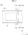
- FIG. 4 illustrates the guide device 1000 according to an embodiment of the present disclosure.
- the guide device 1000 may be observed when viewed from the above.
- the guide device 1000 may include a guide frame 1100.
- the guide frame 1100 may be installed or fixed on the ground.
- the first conveying unit 1200 may be coupled to or installed on the guide frame 1100.
- the first conveying unit 1200 may include a conveyor.
- the first conveying unit 1200 may convey the battery module 50.
- the first conveying unit 1200 may move the battery module 50 along a longitudinal direction (X).
- the guide device 1000 may include the alignment unit 1300.
- the alignment unit 1300 may be coupled or connected to the guide frame 1100.
- the alignment unit 1300 may be rotatably coupled to the guide frame 1100.
- the plurality of alignment units 1300 may be provided.
- the alignment unit 1300 may include a first alignment unit 1300a and a second alignment unit 1300b.
- the alignment unit 1300 may be positioned on the first conveying unit 1200.
- the alignment unit 1300 may align the battery module 50 on the first conveying unit 1200.
- FIG. 5 illustrates that the alignment unit 1300 according to an embodiment of the present disclosure is installed on the guide frame 1100.
- the alignment unit 1300 may include a first link 1310.
- the first link 1310 may include a first link body 1311.
- the first link body 1311 may form a shape that extends from one end and leads to other end.
- the first link 1310 may include a first link pivot part 1312.
- the first link pivot part 1312 may be formed at the one end of the first link body 1311.
- the first link pivot part 1312 may be rotatably coupled to the guide frame 1100.
- the first link 1310 may include a first link connection part 1313.
- the first link connection part 1313 may be formed at the other end of the first link body 1311.
- the first link connection part 1313 may be coupled to a second link 1320.
- the alignment unit 1300 may include the second link 1320.
- the second link 1320 may include a second link body 1321.
- the second link body 1321 may form a shape that extends from one end and leads to other end.
- the second link 1320 may include a second link connection part 1322.
- the second link connection part 1322 may be formed at the one end of the second link body 1321.
- the second link connection part 1322 may be coupled to the first link connection part 1313.
- the second link connection part 1322 may be rotatably coupled to the first link connection part 1313.
- FIG. 6 illustrates that the alignment unit 1300 according to an embodiment of the present disclosure aligns the battery module 50.
- the battery module 50 illustrated in FIG. 4 may move in the longitudinal direction (X), and the alignment unit 1300 may align the battery module 50 by contacting the battery module 50 and applying a force to the battery module 50 as illustrated in FIG. 6 .
- the battery module 50 When the battery module 50 moves in the longitudinal direction (X) by the first conveying unit 1200, the battery module 50 may contact the first link 1310. A length direction of the first link body 1311 may form an inclination with the longitudinal direction (X). When the battery module 50 further moves in the longitudinal direction (X), the battery module 50 may push the first link body 1311 in the longitudinal direction (X).
- the battery module 50 may move along the first link body 1311.
- the second link body 1321 may form a torque with respect to the first link body 1311.
- a front face of the battery module 50 may face and come into contact with the second link body 1321 of the first alignment unit 1300a and the second link body 1321 of the second alignment unit 1300b.
- the battery module 50 may be aligned in an attitude in which the front face of the battery module 50 is directed toward the longitudinal direction (X) to the front.
- the front face of the battery module 50 may indicate a face directed toward the longitudinal direction (X).
- the first link body 1311 When the battery module 50 is aligned, the first link body 1311 may rotate in a direction in which the battery module 50 moves. In other words, when the battery module 50 is aligned, the first link body 1311 may rotate about the first link pivot part 1312 so that the second link 1320 is positioned outside the first conveying unit 1200. Thus, the battery module 50 in an aligned state may be provided to the perforation device 2000 (see FIGS. 2 and 3 ).
- FIG. 7 illustrates the second conveying unit 2200 according to an embodiment of the present disclosure.
- the second conveying unit 2200 may include a roller conveyor.
- the second conveying unit 2200 may load the battery module 50 (see FIG. 1 ).
- the second conveying unit 2200 may be referred to as a "loading unit”.
- the second conveying unit 2200 may move the battery module 50 (see FIG. 1 ) in the longitudinal direction (X).
- the second conveying unit 2200 may include a pair of second conveying frames 2210.
- the pair of second conveying frames 2210 may form a shape extending in the longitudinal direction (X).
- the second conveying frame 2210 may be referred to as a "loading frame”.
- the second conveying unit 2200 may include a second conveying roller 2220.
- a plurality of second conveying rollers 2220 may be provided.
- the second conveying rollers 2220 may be coupled between the pair of conveying frames 2210.
- the second conveying roller 2220 may be referred to as a "loading bar”.
- the second conveying roller 2220 may form a cylindrical shape in which a transverse direction (Y) is a length direction.
- FIG. 8 illustrates that the fixing unit 2400 according to an embodiment of the present disclosure fixes the battery module 50 along the longitudinal direction (X).
- the fixing unit 2400 when viewed from the transverse direction may be observed.
- the fixing unit 2400 may include a vertical fixing module 2410.
- the vertical fixing module 2410 may approach the battery module 50 from above the battery module 50.
- the vertical fixing module 2410 may come into contact with an upper surface of the battery module 50.
- the vertical fixing module 2410 may provide a downward pressure to the battery module 50.
- the vertical fixing module 2410 may suppress a vertical direction movement of the battery module 50.
- the fixing unit 2400 may include a longitudinal fixing module 2420.
- the longitudinal fixing module 2420 may approach the front face or/and rear face of the battery module 50.
- the longitudinal fixing module 2420 may contact the front face or/and rear face of the battery module 50.
- the longitudinal fixing module 2420 may provide a longitudinal pressure to the battery module 50.
- the longitudinal fixing module 2420 may suppress a longitudinal movement of the battery module 50.
- the longitudinal fixing module 2420 may include a first longitudinal fixing module 2421 and a second longitudinal fixing module 2422.
- the first longitudinal fixing module 2421 may approach the battery module 50 from behind the battery module 50.
- the first longitudinal fixing module 2421 may contact the rear face of the battery module 50 and provide a pressure to the battery module 50.
- the second longitudinal fixing module 2422 may approach the battery module 50 from the front of the battery module 50.
- the second longitudinal fixing module 2422 may contact the front face of the battery module 50 and provide a pressure to the battery module 50
- FIG. 9 illustrates that the perforation device 2000 according to an embodiment of the present disclosure perforates the battery module 50 in the transverse direction (Y).
- the fixing unit 2400 and the perforation unit 2500 when viewed from above may be observed.
- a plurality of first longitudinal fixing modules 2421 may be provided.
- the plurality of first longitudinal fixing modules 2421 may be disposed to be spaced apart from each other in the transverse direction (Y) or a vertical direction (Z).
- the first longitudinal fixing modules 2421 may include a pair of first longitudinal fixing modules 2421.
- a plurality of second longitudinal fixing modules 2422 may be provided.
- the plurality of second longitudinal fixing modules 2422 may be disposed to be spaced apart from each other in the transverse direction (Y) or the vertical direction (Z).
- the second longitudinal fixing modules 2422 may include a pair of second longitudinal fixing modules 2422.
- the fixing unit 2400 may include a transverse fixing module 2430.
- the transverse fixing module 2430 may suppress a transverse movement of the battery module 50.
- the transverse fixing module 2430 may include a second transverse fixing module 2432.
- the second transverse fixing module 2432 may suppress a positive Y-axis movement of the battery module 50.
- a plurality of second transverse fixing modules 2432 may be provided.
- the second transverse fixing modules 2432 may include a pair of second transverse fixing modules 2432.
- the pair of second transverse fixing modules 2432 may be disposed to be spaced apart from each other in the transverse direction (Y) or the vertical direction (Z).
- the perforation unit 2500 may include a transverse perforation module 2530.
- the transverse perforation module 2530 may be positioned opposite the transverse fixing module 2430.
- the transverse perforation module 2530 may be positioned opposite the second transverse fixing modules 2432.
- the second transverse fixing modules 2432, the battery module 50, and the transverse perforation module 2530 may be sequentially disposed.
- the transverse perforation module 2530 may approach the battery module 50.
- the transverse perforation module 2530 may move toward, for example, between the pair of second transverse fixing modules 2432.
- the transverse perforation module 2530 may perforate the battery module 50.
- the transverse perforation module 2530 may push the battery module 50 in a direction in which the transverse perforation module 2530 moves.
- the transverse fixing module 2430 may suppress the battery module 50 from moving in the transverse direction (Y).
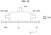
- FIG. 10 illustrates that the fixing unit 2400 according to an embodiment of the present disclosure fixes the battery module 50 along the transverse direction (Y).
- the fixing unit 2400 when viewed from the longitudinal direction may be observed.
- the transverse fixing module 2430 may include a first transverse fixing module 2431 and the second transverse fixing module 2432.
- the first transverse fixing module 2431 and the second transverse fixing module 2432 may be disposed with the battery module 50 interposed therebetween.
- the first transverse fixing module 2431 and the second transverse fixing module 2432 may approach the battery module 50 and contact the battery module 50.
- the first transverse fixing module 2431 and the second transverse fixing module 2432 may suppress the battery module 50 from moving in the transverse direction (Y).
- FIG. 11 illustrates that the perforation device 2000 according to an embodiment of the present disclosure perforates the battery module 50 in the longitudinal direction (X).
- the fixing unit 2400 and the perforation unit 2500 when viewed from above may be observed.
- a plurality of first transverse fixing modules 2431 may be provided.
- the plurality of first transverse fixing modules 2431 may be disposed to be spaced apart from each other in the longitudinal direction (X) or the vertical direction (Z).
- the first transverse fixing modules 2431 may include a pair of first transverse fixing modules 2431.
- the plurality of second transverse fixing modules 2432 may be provided.
- the plurality of second transverse fixing modules 2432 may be disposed to be spaced apart from each other in the longitudinal direction (X) or the vertical direction (Z).
- the second transverse fixing modules 2432 may include a pair of second transverse fixing modules 2432.
- the perforation unit 2500 may include a longitudinal perforation module 2520.
- the longitudinal perforation module 2520 may be positioned opposite the longitudinal fixing module 2420.
- the longitudinal perforation module 2520 may be positioned opposite the first longitudinal fixing modules 2421.
- the first longitudinal fixing modules 2421, the battery module 50, and the longitudinal perforation module 2520 may be sequentially disposed.
- the longitudinal perforation module 2520 may approach the battery module 50.
- the longitudinal perforation module 2520 may move toward, for example, between the pair of first longitudinal fixing modules 2421.
- the longitudinal perforation module 2520 may perforate the battery module 50.
- the longitudinal perforation module 2520 may push the battery module 50 in a direction in which the longitudinal perforation module 2520 moves.
- the longitudinal fixing module 2420 may suppress the battery module 50 from moving in the longitudinal direction (X).
- FIG. 12 illustrates that the fixing unit 2400 according to an embodiment of the present disclosure fixes the battery module 50 along the longitudinal direction (X) and the transverse direction (Y).
- the fixing unit 2400 when viewed from above may be observed.
- FIG. 13 illustrates that the perforation device 2000 according to an embodiment of the present disclosure perforates the battery module 50 in the vertical direction (Z).
- the fixing unit 2400 and the perforation unit 2500 when viewed from the transverse direction may be observed.
- the longitudinal fixing module 2420 and the transverse fixing module 2430 may fix the battery module 50.
- the perforation unit 2500 may include a vertical perforation module 2510.
- the vertical perforation module 2510 may move toward the battery module 50 from above the battery module 50.
- the vertical perforation module 2510 may move toward between adjacent second conveying rollers 2220 (see FIG. 7 ) among the plurality of second conveying rollers 2220 (see FIG. 7 ).
- the vertical perforation module 2510 may perforate the battery module 50.
- the vertical fixing module 2410 may fix the battery module 50.
- the plurality of vertical fixing modules 2410 may be provided.
- the plurality of vertical fixing modules 2410 may be disposed to be spaced apart from each other in the longitudinal direction (X) or/and the transverse direction (Y).
- the vertical perforation module 2510 may be disposed between the plurality of vertical fixing modules 2410.
- the alignment unit 1300 may align the battery module 50 loaded on the first conveying unit 1200.
- the aligned battery module 50 may be loaded on the second conveying unit 2200.
- the identification unit 2300 may obtain appearance information of the battery module 50. Alternatively, the identification unit 2300 may obtain information about the battery module 50 from the battery tag 52.
- the control unit 3000 may obtain the fifth signal S5 from the identification unit 2300.
- the fifth signal S5 may include an image or information about the battery module 50.
- the sensor unit 2800 may generate the sixth signal S6 including information about the position and/or attitude of the battery module 50 loaded on the second conveying unit 2200.
- the control unit 3000 may determine, based on the input signals S1, S2, S5 and S6, at which position the battery module 50 loaded on the second conveying unit 2200 is to be perforated. That is, the control unit 3000 may generate the fourth signal S4 based on the input signals S1, S2, S5 and S6.
- the second conveying unit 2200 may adjust the position of the battery module 50 in response to the fourth signal S4.
- the fixing unit 2400 may fix the battery module 50 in response to the fourth signal S4.
- the perforation unit 2500 may move toward a specific point of the battery module 50 in response to the fourth signal S4 and perforate the battery module 50.
- the control unit 3000 may be a separate and independent unit from the guide device 1000 and the perforation device 2000. For another example, at least a portion of the control unit 3000 may be included in the guide device 1000. For another example, at least a portion of the control unit 3000 may be included in the perforation device 2000.
- the perforation device 2000 may be operated independently without the guide device 1000.
- the perforation device 2000 may include at least one of the control unit 3000, the input unit 4000, and the communication unit 5000.
- the input signals S5 and S6 may include at least one of the fifth signal S5 and the sixth signal S6.
- the control unit 3000 may generate the fourth signal S4 based on the input signals S5 and S6.
- the fourth signal S4 may be provided to at least one of the second conveying unit 2200, the fixing unit 2400, the perforation unit 2500, the fire extinguishing unit 2600, and the exhaust unit 2700 and control them.
- the perforation unit 2500 that moves toward the battery module 50 and is inserted into the battery module 50 may be separated from the battery module 50 while retreating.
- the fixing unit 2400 may suppress the movement of the battery module 50 so as to prevent the battery module 50 from being dragged by the perforation unit 2500.
- the first transverse fixing module 2431 may suppress the transverse direction (Y) movement of the battery module 50 while contacting the battery module 50.
- the second longitudinal fixing module 2422 may suppress the longitudinal direction (X) movement of the battery module 50 while contacting the battery module 50.
- the vertical fixing module 2410 may include a pair of vertical fixing modules 2410 that are spaced apart from each other. The vertical perforation module 2510 may move toward the pair of vertical fixing modules 2410 and perforate the battery module 50.
- the vertical fixing module 2410 may suppress the vertical direction (Z) movement of the battery module 50 while contacting the battery module 50.
Landscapes
- Engineering & Computer Science (AREA)
- Mechanical Engineering (AREA)
- Life Sciences & Earth Sciences (AREA)
- Forests & Forestry (AREA)
- Environmental & Geological Engineering (AREA)
- Chemical & Material Sciences (AREA)
- Chemical Kinetics & Catalysis (AREA)
- Electrochemistry (AREA)
- General Chemical & Material Sciences (AREA)
- Battery Mounting, Suspending (AREA)
Abstract
Description
- The present disclosure relates to a perforation device and a perforation system including the same. More particularly, the present disclosure relates to a perforation device for perforating a secondary battery and a perforation system including the same.
- A secondary battery has energy therein. Therefore, it is necessary to stably discard secondary batteries that have reached the end of their life or are damaged. Conventional secondary batteries were subjected to a chemical immersion discharge in which they are broken and immersed in water. In particular, in case of a pouch-type secondary battery, a pouch of the secondary battery was cut before immersing the secondary battery.
- When the pouch of the secondary battery is cut, it is difficult to determine whether or not the cut is made and the size of the cut, so the secondary battery may not be discharged. In this case, a thermal runaway accident may occur in the secondary battery. Therefore, a method may be considered to stably discard the secondary battery, that has reached the end of its life or is damaged, by stably perforating the secondary battery.
- (Patent Document 1)
KR 10-2000-0042144 A - An object of the present disclosure is to address the above-described and other problems.
- Another object of the present disclosure is to provide a perforation device perforating a battery module by changing a perforation position depending on a size or a structure of the battery module, and a perforation system including the same.
- Another object of the present disclosure is to provide a perforation device, in which a position fixing a battery module changes depending on a position of a perforation unit perforating the battery module, and a perforation system including the same.
- Another object of the present disclosure is to provide a perforation system including a guide device conveying and aligning a battery module and a perforation device perforating the battery module.
- In order to achieve the above-described and other objects and needs, in one aspect of the present disclosure, there is provided a perforation device perforating a battery module, the perforation device comprising a loading unit configured to convey and load the battery module in a longitudinal direction; a fixing unit configured to fix the battery module; and a perforation unit configured to approach the battery module and perforate the battery module, wherein when the perforation unit approaches the battery module, the fixing unit contacts the battery module on an opposite side of the perforation unit with respect to the battery module and suppresses a movement of the battery module.
- In another aspect of the present disclosure, there is provided a perforation system comprising a guide device configured to convey and align a battery module; and a perforation device configured to perforate the battery module, wherein the guide device includes a guide frame; a first conveying unit installed in the guide frame, the first conveying unit being configured to convey the battery module and provide the battery module to the perforation device; and an alignment unit configured to align the battery module, wherein the perforation device includes a loading unit configured to convey and load the battery module in a longitudinal direction; a fixing unit configured to fix the battery module; and a perforation unit configured to approach the battery module and perforate the battery module.
- Effects of the perforation device and the perforation system including the same according to the present disclosure are described as follows.
- According to at least one aspect of the present disclosure, the present disclosure can provide a perforation device perforating a battery module by changing a perforation position depending on a size or a structure of the battery module, and a perforation system including the same.
- According to at least one aspect of the present disclosure, the present disclosure can provide a perforation device, in which a position fixing a battery module changes depending on a position of a perforation unit perforating the battery module, and a perforation system including the same.
- According to at least one aspect of the present disclosure, the present disclosure can provide a perforation system including a guide device conveying and aligning a battery module and a perforation device perforating the battery module.
- Additional scope of applicability of the present disclosure will become apparent from the detailed description given blow. However, it should be understood that the detailed description and specific examples such as embodiments of the present disclosure are given merely by way of example, since various changes and modifications within the spirit and scope of the present disclosure will become apparent to those skilled in the art from the detailed description.
- The accompanying drawings, which are included to provide a further understanding of the disclosure and are incorporated in and constitute a part of the disclosure, illustrate embodiments of the disclosure and together with the description serve to explain the principle of the disclosure.
-
FIG. 1 illustrates a battery module. -
FIG. 2 illustrates a perforation system according to an embodiment of the present disclosure when viewed from its side. -
FIG. 3 is a block diagram of a perforation system according to an embodiment of the present disclosure. -
FIG. 4 illustrates a guide device according to an embodiment of the present disclosure. -
FIG. 5 illustrates that an alignment unit according to an embodiment of the present disclosure is installed on a guide frame. -
FIG. 6 illustrates that an alignment unit according to an embodiment of the present disclosure aligns a battery module. -
FIG. 7 illustrates a second conveying unit according to an embodiment of the present disclosure. -
FIG. 8 illustrates that a fixing unit according to an embodiment of the present disclosure fixes a battery module along a longitudinal direction. -
FIG. 9 illustrates that a perforation device according to an embodiment of the present disclosure perforates a battery module in a transverse direction. -
FIG. 10 illustrates that a fixing unit according to an embodiment of the present disclosure fixes a battery module along a transverse direction. -
FIG. 11 illustrates that a perforation device according to an embodiment of the present disclosure perforates a battery module in a longitudinal direction. -
FIG. 12 illustrates that a fixing unit according to an embodiment of the present disclosure fixes a battery module along a longitudinal direction and a transverse direction. -
FIG. 13 illustrates that a perforation device according to an embodiment of the present disclosure perforates a battery module in a vertical direction. - Reference will now be made in detail to embodiments of the disclosure, examples of which are illustrated in the accompanying drawings. Wherever possible, the same reference numbers will be used throughout the drawings to refer to the same or like parts. In general, a suffix such as "module" and "unit" may be used to refer to elements or components. Use of such a suffix herein is merely intended to facilitate description of the present disclosure, and the suffix itself is not intended to give any special meaning or function. It will be noted that a detailed description of known arts will be omitted if it is determined that the detailed description of the known arts can obscure the embodiments of the disclosure. The accompanying drawings are used to help easily understand various technical features and it should be understood that embodiments presented herein are not limited by the accompanying drawings. As such, the present disclosure should be construed to extend to any alterations, equivalents and substitutes in addition to those which are particularly set out in the accompanying drawings.
- The terms including an ordinal number such as first, second, etc. may be used to describe various components, but the components are not limited by such terms. The terms are used only for the purpose of distinguishing one component from other components.
- When any component is described as "being connected" or "being coupled" to other component, this should be understood to mean that another component may exist between them, although any component may be directly connected or coupled to the other component. In contrast, when any component is described as "being directly connected" or "being directly coupled" to other component, this should be understood to mean that no component exists between them.
- A singular expression can include a plural expression as long as it does not have an apparently different meaning in context.
- In the present disclosure, terms "include" and "have" should be understood to be intended to designate that illustrated features, numbers, steps, operations, components, parts or combinations thereof are present and not to preclude the existence of one or more different features, numbers, steps, operations, components, parts or combinations thereof, or the possibility of the addition thereof.
- In the drawings, sizes of the components may be exaggerated or reduced for convenience of explanation. For example, the size and the thickness of each component illustrated in the drawings are arbitrarily illustrated for convenience of explanation, and thus the present disclosure is not limited thereto unless specified as such.
- If any embodiment is implementable differently, a specific order of processes may be performed differently from the order described. For example, two consecutively described processes may be performed substantially at the same time, or performed in the order opposite to the described order.
- In the following embodiments, when layers, areas, components, etc. are connected, the following embodiments include both the case where layers, areas, and components are directly connected, and the case where layers, areas, and components are indirectly connected to other layers, areas, and components intervening between them. For example, when layers, areas, components, etc. are electrically connected, the present disclosure includes both the case where layers, areas, and components are directly electrically connected, and the case where layers, areas, and components are indirectly electrically connected to other layers, areas, and components intervening between them.
-
FIG. 1 illustrates a battery module. - Referring to
FIG. 1 , abattery module 50 may include abattery body 51. Thebattery body 51 may include a plurality of battery cells. For example, thebattery body 51 may include a plurality of battery cells and a battery case accommodating the plurality of battery cells. - The
battery module 50 may include abattery tag 52. Thebattery tag 52 may be formed on an outer surface of thebattery body 51. For example, thebattery tag 52 may be a sticker attached to the outer surface of thebattery body 51. - The
battery tag 52 may include information on thebattery module 50. For example, thebattery tag 52 may display a brand including information about a manufacturer of thebattery module 50. For example, thebattery tag 52 may display a serial number including specification information of thebattery module 50. For example, thebattery tag 52 may display a bar-code or QR-code including information on thebattery module 50. - Information on the
battery module 50 that can be known from thebattery tag 52 may include the size of thebattery module 50. Information on thebattery module 50 that can be known from thebattery tag 52 may include at least one of a manufacturing year, a charging method, and an electrode material of thebattery module 50. -
FIG. 2 illustrates aperforation system 10 according to an embodiment of the present disclosure when viewed from its side.FIG. 3 is a block diagram of theperforation system 10 according to an embodiment of the present disclosure. - Referring to
FIGS. 1 to 3 , theperforation system 10 may include aguide device 1000. Theguide device 1000 may operate based on a received signal. For example, theguide device 1000 may operate based on a third signal S3. - The
guide device 1000 may convey thebattery module 50. For example, theguide device 1000 may include a first conveyingunit 1200. The first conveyingunit 1200 may convey thebattery module 50. Thebattery module 50 conveyed by the first conveyingunit 1200 may be thebattery module 50 to be discarded. - The
guide device 1000 may align thebattery module 50. For example, theguide device 1000 may include analignment unit 1300. Thealignment unit 1300 may align thebattery modules 50. - The
perforation system 10 may include aperforation device 2000. Theperforation device 2000 may operate based on a signal. For example, theperforation device 2000 may operate based on a fourth signal S4. - The
perforation device 2000 may receive thebattery module 50 from theguide device 1000. Theperforation device 2000 may perforate thebattery module 50. The electrical stability of theperforated battery module 50 may be higher than the electrical stability of thenon-perforated battery module 50. - The
perforation device 2000 may include a second conveyingunit 2200. The second conveyingunit 2200 may load thebattery module 50. The second conveyingunit 2200 may move thebattery module 50. - The
perforation device 2000 may include anidentification unit 2300. Theidentification unit 2300 may identify thebattery module 50. For example, theidentification unit 2300 may include a camera. The camera of theidentification unit 2300 may obtain an image of thebattery tag 52. - For another example, the camera of the
identification unit 2300 may obtain an image of thebattery module 50. The image of thebattery module 50 may include information on the size of thebattery module 50. For example, theidentification unit 2300 or acontrol unit 3000 may analyze the image of thebattery module 50 to acquire size information of thebattery module 50. - The
identification unit 2300 may generate a signal. For example, theidentification unit 2300 may generate a fifth signal S5. For example, the fifth signal S5 may include image information on thebattery module 50 acquired by theidentification unit 2300. For another example, the fifth signal S5 may include image information on thebattery tag 52 acquired by theidentification unit 2300. The fifth signal S5 may be transmitted to thecontrol unit 3000. - The
perforation device 2000 may include afixing unit 2400. Thefixing unit 2400 may fix thebattery module 50. For example, thefixing unit 2400 may fix thebattery module 50 in at least one of a front-rear direction, an up-down direction, and a left-right direction of thebattery module 50. - The front-rear direction, the up-down direction, and the left-right direction of the
battery module 50 may mean a front-rear direction, an up-down direction, and a left-right direction of theperforation device 2000. The front-rear direction may be a "longitudinal direction". The up-down direction may be a "vertical direction". The left-right direction may be a "transverse direction". In the cartesian coordinate, the longitudinal direction may be parallel to an X-axis, the transverse direction may be parallel to a Y-axis, and the vertical direction may be parallel to a Z-axis. - The
perforation device 2000 may include aperforation unit 2500. Theperforation unit 2500 may perforate thebattery module 50. Theperforation unit 2500 may include a drill. Theperforated battery module 50 has the possibility of burning by a chemical reaction. Alternatively, in a process of perforating thebattery module 50, there is a possibility that a fire may occur in thebattery module 50. - The
perforation device 2000 may include afire extinguishing unit 2600 and anexhaust unit 2700. When a fire occurs in thebattery module 50, thefire extinguishing unit 2600 extinguishes the fire, and theexhaust unit 2700 exhausts smoke generated during the fire to the outside. Theexhaust unit 2700 may discharge dust or chemicals generated in the process of perforating thebattery module 50 to the outside. - The
perforation device 2000 may include asensor unit 2800. Thesensor unit 2800 may detect a position and an attitude of thebattery module 50. Information about the sensed position and attitude of thebattery module 50 may be used to control at least one of the second conveyingunit 2200, thefixing unit 2400, and theperforation unit 2500. - The
sensor unit 2800 may include a smoke sensor that detects smoke. Thesensor unit 2800 may include a flame detection sensor that detects a flame. Information on the detected smoke or/and flame may be used to control thefire extinguishing unit 2600 and theexhaust unit 2700. - The
sensor unit 2800 may generate a signal. For example, thesensor unit 2800 may generate a sixth signal S6. The sixth signal S6 may include information about the position and the attitude of thebattery module 50. The sixth signal S6 may include information about smoke or/and flame. The sixth signal S6 may be transmitted to thecontrol unit 3000. - The
perforation system 10 may include thecontrol unit 3000. Thecontrol unit 3000 may process signals or information. Thecontrol unit 3000 may process calculations. Thecontrol unit 3000 may be implemented by at least one of a computer, a laptop, a processor, a server, and a printed circuit board (PCB). - The
perforation system 10 may include aninput unit 4000. Theinput unit 4000 may obtain a command input by, for example, a user or an administrator. The command obtained by theinput unit 4000 may include information related to control of theguide device 1000 or/and theperforation device 2000. - The
input unit 4000 may generate a signal. For example, theinput unit 4000 may generate afirst signal S 1. Thefirst signal S 1 may include information related to control of theguide device 1000 or/and theperforation device 2000. - The
perforation system 10 may include acommunication unit 5000. Thecommunication unit 5000 may transmit and receive signals or/and information with an external device. Thecommunication unit 5000 may generate or receive a signal. Thecommunication unit 5000 may transmit and receive signals or/and information with the external device in a wired or/and wireless manner. - For example, the
communication unit 5000 may generate a second signal S2 and transmit the second signal S2 to thecontrol unit 3000. Thecommunication unit 5000 may receive a seventh signal S7 from thecontrol unit 3000. The second signal S2 may include information related to the control of theperforation system 10. The seventh signal S7 may include information about a state of theperforation system 10. - The
control unit 3000 may transmit and receive signals. For example, thecontrol unit 3000 may generate a new signal based on the received signal. For example, thecontrol unit 3000 may generate the output signals S3, S4 and S7 based on the input signals S1, S2, S5 and S6. The input signals S1, S2, S5 and S6 may be signals to be received by thecontrol unit 3000. The output signals S3, S4 and S7 may be signals generated by thecontrol unit 3000. - The input signals
S 1, S2, S5 and S6 may include at least one of thefirst signal S 1, the second signal S2, the fifth signal S5, and the sixth signal S6. The output signals S3, S4 and S7 may include at least one of the third signal S3, the fourth signal S4, and the seventh signal S7. - The third signal S3 may include information related to the control of the
guide device 2000. For example, the first conveyingunit 1200 may convey thebattery module 50 based on the third signal S3. For example, thealignment unit 1300 may align thebattery module 50 based on the third signal S3. - The fourth signal S4 may include information related to the control of the
perforation device 3000. For example, the second conveyingunit 2200 may move thebattery module 50 based on the fourth signal S4. - For example, the
fixing unit 2400 may adjust the position and/or attitude of thebattery module 50 based on the fourth signal S4. For example, thefixing unit 2400 may fix thebattery module 50 based on the fourth signal S4. - For example, the
perforation unit 2500 may perforate thebattery module 50 based on the fourth signal S4. For example, the fourth signal S4 may include information on a perforation position of thebattery module 50. - For example, the
fire extinguishing unit 2600 and theexhaust unit 2700 may operate based on the fourth signal S4. For example, thefire extinguishing unit 2600 may inject a fire extinguishing agent toward a fire point based on the fourth signal S4. -
FIG. 4 illustrates theguide device 1000 according to an embodiment of the present disclosure. InFIG. 4 , theguide device 1000 may be observed when viewed from the above. - Referring to
FIG. 4 , theguide device 1000 may include aguide frame 1100. Theguide frame 1100 may be installed or fixed on the ground. The first conveyingunit 1200 may be coupled to or installed on theguide frame 1100. - The first conveying
unit 1200 may include a conveyor. The first conveyingunit 1200 may convey thebattery module 50. For example, the first conveyingunit 1200 may move thebattery module 50 along a longitudinal direction (X). - The
guide device 1000 may include thealignment unit 1300. Thealignment unit 1300 may be coupled or connected to theguide frame 1100. For example, thealignment unit 1300 may be rotatably coupled to theguide frame 1100. - The plurality of
alignment units 1300 may be provided. For example, thealignment unit 1300 may include afirst alignment unit 1300a and asecond alignment unit 1300b. Thealignment unit 1300 may be positioned on the first conveyingunit 1200. Thealignment unit 1300 may align thebattery module 50 on the first conveyingunit 1200. -
FIG. 5 illustrates that thealignment unit 1300 according to an embodiment of the present disclosure is installed on theguide frame 1100. - Referring to
FIG. 5 , thealignment unit 1300 may include afirst link 1310. Thefirst link 1310 may include afirst link body 1311. Thefirst link body 1311 may form a shape that extends from one end and leads to other end. - The
first link 1310 may include a firstlink pivot part 1312. The firstlink pivot part 1312 may be formed at the one end of thefirst link body 1311. The firstlink pivot part 1312 may be rotatably coupled to theguide frame 1100. - The
first link 1310 may include a firstlink connection part 1313. The firstlink connection part 1313 may be formed at the other end of thefirst link body 1311. The firstlink connection part 1313 may be coupled to asecond link 1320. - The
alignment unit 1300 may include thesecond link 1320. Thesecond link 1320 may include asecond link body 1321. Thesecond link body 1321 may form a shape that extends from one end and leads to other end. - The
second link 1320 may include a secondlink connection part 1322. The secondlink connection part 1322 may be formed at the one end of thesecond link body 1321. The secondlink connection part 1322 may be coupled to the firstlink connection part 1313. For example, the secondlink connection part 1322 may be rotatably coupled to the firstlink connection part 1313. -
FIG. 6 illustrates that thealignment unit 1300 according to an embodiment of the present disclosure aligns thebattery module 50. - Referring to
FIGS. 4 to 6 , thebattery module 50 illustrated inFIG. 4 may move in the longitudinal direction (X), and thealignment unit 1300 may align thebattery module 50 by contacting thebattery module 50 and applying a force to thebattery module 50 as illustrated inFIG. 6 . - When the
battery module 50 moves in the longitudinal direction (X) by the first conveyingunit 1200, thebattery module 50 may contact thefirst link 1310. A length direction of thefirst link body 1311 may form an inclination with the longitudinal direction (X). When thebattery module 50 further moves in the longitudinal direction (X), thebattery module 50 may push thefirst link body 1311 in the longitudinal direction (X). - By a force of the
battery module 50 pushing thefirst link body 1311 and a torque applied to thebattery module 50 by thefirst link 1310, thebattery module 50 may move along thefirst link body 1311. - The
second link body 1321 may form a torque with respect to thefirst link body 1311. - A front face of the
battery module 50 may face and come into contact with thesecond link body 1321 of thefirst alignment unit 1300a and thesecond link body 1321 of thesecond alignment unit 1300b. - Hence, the
battery module 50 may be aligned in an attitude in which the front face of thebattery module 50 is directed toward the longitudinal direction (X) to the front. The front face of thebattery module 50 may indicate a face directed toward the longitudinal direction (X). - When the
battery module 50 is aligned, thefirst link body 1311 may rotate in a direction in which thebattery module 50 moves. In other words, when thebattery module 50 is aligned, thefirst link body 1311 may rotate about the firstlink pivot part 1312 so that thesecond link 1320 is positioned outside the first conveyingunit 1200. Thus, thebattery module 50 in an aligned state may be provided to the perforation device 2000 (seeFIGS. 2 and3 ). -
FIG. 7 illustrates the second conveyingunit 2200 according to an embodiment of the present disclosure. - Referring to
FIG. 7 , the second conveyingunit 2200 may include a roller conveyor. The second conveyingunit 2200 may load the battery module 50 (seeFIG. 1 ). The second conveyingunit 2200 may be referred to as a "loading unit". The second conveyingunit 2200 may move the battery module 50 (seeFIG. 1 ) in the longitudinal direction (X). - The second conveying
unit 2200 may include a pair of second conveyingframes 2210. The pair of second conveyingframes 2210 may form a shape extending in the longitudinal direction (X). The second conveyingframe 2210 may be referred to as a "loading frame". - The second conveying
unit 2200 may include a second conveyingroller 2220. A plurality of second conveyingrollers 2220 may be provided. The second conveyingrollers 2220 may be coupled between the pair of conveyingframes 2210. The second conveyingroller 2220 may be referred to as a "loading bar". The second conveyingroller 2220 may form a cylindrical shape in which a transverse direction (Y) is a length direction. -
FIG. 8 illustrates that thefixing unit 2400 according to an embodiment of the present disclosure fixes thebattery module 50 along the longitudinal direction (X). InFIG. 8 , thefixing unit 2400 when viewed from the transverse direction may be observed. - Referring to
FIG. 8 , thefixing unit 2400 may include avertical fixing module 2410. Thevertical fixing module 2410 may approach thebattery module 50 from above thebattery module 50. Thevertical fixing module 2410 may come into contact with an upper surface of thebattery module 50. Thevertical fixing module 2410 may provide a downward pressure to thebattery module 50. Thevertical fixing module 2410 may suppress a vertical direction movement of thebattery module 50. - The
fixing unit 2400 may include alongitudinal fixing module 2420. Thelongitudinal fixing module 2420 may approach the front face or/and rear face of thebattery module 50. Thelongitudinal fixing module 2420 may contact the front face or/and rear face of thebattery module 50. Thelongitudinal fixing module 2420 may provide a longitudinal pressure to thebattery module 50. Thelongitudinal fixing module 2420 may suppress a longitudinal movement of thebattery module 50. - The
longitudinal fixing module 2420 may include a firstlongitudinal fixing module 2421 and a secondlongitudinal fixing module 2422. The firstlongitudinal fixing module 2421 may approach thebattery module 50 from behind thebattery module 50. The firstlongitudinal fixing module 2421 may contact the rear face of thebattery module 50 and provide a pressure to thebattery module 50. The secondlongitudinal fixing module 2422 may approach thebattery module 50 from the front of thebattery module 50. The secondlongitudinal fixing module 2422 may contact the front face of thebattery module 50 and provide a pressure to thebattery module 50 -
FIG. 9 illustrates that theperforation device 2000 according to an embodiment of the present disclosure perforates thebattery module 50 in the transverse direction (Y). InFIG. 9 , thefixing unit 2400 and theperforation unit 2500 when viewed from above may be observed. - Referring to
FIGS. 8 and9 , a plurality of firstlongitudinal fixing modules 2421 may be provided. The plurality of firstlongitudinal fixing modules 2421 may be disposed to be spaced apart from each other in the transverse direction (Y) or a vertical direction (Z). For example, the firstlongitudinal fixing modules 2421 may include a pair of firstlongitudinal fixing modules 2421. - A plurality of second
longitudinal fixing modules 2422 may be provided. The plurality of secondlongitudinal fixing modules 2422 may be disposed to be spaced apart from each other in the transverse direction (Y) or the vertical direction (Z). For example, the secondlongitudinal fixing modules 2422 may include a pair of secondlongitudinal fixing modules 2422. - The
fixing unit 2400 may include atransverse fixing module 2430. Thetransverse fixing module 2430 may suppress a transverse movement of thebattery module 50. - The
transverse fixing module 2430 may include a secondtransverse fixing module 2432. The secondtransverse fixing module 2432 may suppress a positive Y-axis movement of thebattery module 50. - A plurality of second transverse fixing
modules 2432 may be provided. For example, the second transverse fixingmodules 2432 may include a pair of second transverse fixingmodules 2432. The pair of second transverse fixingmodules 2432 may be disposed to be spaced apart from each other in the transverse direction (Y) or the vertical direction (Z). - The
perforation unit 2500 may include atransverse perforation module 2530. Thetransverse perforation module 2530 may be positioned opposite thetransverse fixing module 2430. For example, thetransverse perforation module 2530 may be positioned opposite the second transverse fixingmodules 2432. The second transverse fixingmodules 2432, thebattery module 50, and thetransverse perforation module 2530 may be sequentially disposed. - The
transverse perforation module 2530 may approach thebattery module 50. Thetransverse perforation module 2530 may move toward, for example, between the pair of second transverse fixingmodules 2432. Thetransverse perforation module 2530 may perforate thebattery module 50. - In a process in which the
transverse perforation module 2530 perforates thebattery module 50, thetransverse perforation module 2530 may push thebattery module 50 in a direction in which thetransverse perforation module 2530 moves. Thetransverse fixing module 2430 may suppress thebattery module 50 from moving in the transverse direction (Y). -
FIG. 10 illustrates that thefixing unit 2400 according to an embodiment of the present disclosure fixes thebattery module 50 along the transverse direction (Y). InFIG. 10 , thefixing unit 2400 when viewed from the longitudinal direction may be observed. - Referring to
FIG. 10 , thetransverse fixing module 2430 may include a firsttransverse fixing module 2431 and the secondtransverse fixing module 2432. The firsttransverse fixing module 2431 and the secondtransverse fixing module 2432 may be disposed with thebattery module 50 interposed therebetween. The firsttransverse fixing module 2431 and the secondtransverse fixing module 2432 may approach thebattery module 50 and contact thebattery module 50. The firsttransverse fixing module 2431 and the secondtransverse fixing module 2432 may suppress thebattery module 50 from moving in the transverse direction (Y). -
FIG. 11 illustrates that theperforation device 2000 according to an embodiment of the present disclosure perforates thebattery module 50 in the longitudinal direction (X). InFIG. 11 , thefixing unit 2400 and theperforation unit 2500 when viewed from above may be observed. - Referring to
FIGS. 10 and11 , a plurality of firsttransverse fixing modules 2431 may be provided. The plurality of firsttransverse fixing modules 2431 may be disposed to be spaced apart from each other in the longitudinal direction (X) or the vertical direction (Z). For example, the firsttransverse fixing modules 2431 may include a pair of firsttransverse fixing modules 2431. - The plurality of second transverse fixing
modules 2432 may be provided. The plurality of second transverse fixingmodules 2432 may be disposed to be spaced apart from each other in the longitudinal direction (X) or the vertical direction (Z). For example, the second transverse fixingmodules 2432 may include a pair of second transverse fixingmodules 2432. - The
perforation unit 2500 may include alongitudinal perforation module 2520. Thelongitudinal perforation module 2520 may be positioned opposite thelongitudinal fixing module 2420. For example, thelongitudinal perforation module 2520 may be positioned opposite the firstlongitudinal fixing modules 2421. The firstlongitudinal fixing modules 2421, thebattery module 50, and thelongitudinal perforation module 2520 may be sequentially disposed. - The
longitudinal perforation module 2520 may approach thebattery module 50. Thelongitudinal perforation module 2520 may move toward, for example, between the pair of firstlongitudinal fixing modules 2421. Thelongitudinal perforation module 2520 may perforate thebattery module 50. - In a process in which the
longitudinal perforation module 2520 perforates thebattery module 50, thelongitudinal perforation module 2520 may push thebattery module 50 in a direction in which thelongitudinal perforation module 2520 moves. Thelongitudinal fixing module 2420 may suppress thebattery module 50 from moving in the longitudinal direction (X). -
FIG. 12 illustrates that thefixing unit 2400 according to an embodiment of the present disclosure fixes thebattery module 50 along the longitudinal direction (X) and the transverse direction (Y). InFIG. 12 , thefixing unit 2400 when viewed from above may be observed. -
FIG. 13 illustrates that theperforation device 2000 according to an embodiment of the present disclosure perforates thebattery module 50 in the vertical direction (Z). InFIG. 13 , thefixing unit 2400 and theperforation unit 2500 when viewed from the transverse direction may be observed. - Referring to
FIGS. 12 and13 , thelongitudinal fixing module 2420 and thetransverse fixing module 2430 may fix thebattery module 50. Theperforation unit 2500 may include avertical perforation module 2510. Thevertical perforation module 2510 may move toward thebattery module 50 from above thebattery module 50. Thevertical perforation module 2510 may move toward between adjacent second conveying rollers 2220 (seeFIG. 7 ) among the plurality of second conveying rollers 2220 (seeFIG. 7 ). Thevertical perforation module 2510 may perforate thebattery module 50. - For another example, the
vertical fixing module 2410 may fix thebattery module 50. For example, the plurality ofvertical fixing modules 2410 may be provided. The plurality ofvertical fixing modules 2410 may be disposed to be spaced apart from each other in the longitudinal direction (X) or/and the transverse direction (Y). Thevertical perforation module 2510 may be disposed between the plurality ofvertical fixing modules 2410. - Referring to
FIGS. 1 to 13 , thealignment unit 1300 may align thebattery module 50 loaded on the first conveyingunit 1200. The alignedbattery module 50 may be loaded on the second conveyingunit 2200. - The
identification unit 2300 may obtain appearance information of thebattery module 50. Alternatively, theidentification unit 2300 may obtain information about thebattery module 50 from thebattery tag 52. Thecontrol unit 3000 may obtain the fifth signal S5 from theidentification unit 2300. The fifth signal S5 may include an image or information about thebattery module 50. Thesensor unit 2800 may generate the sixth signal S6 including information about the position and/or attitude of thebattery module 50 loaded on the second conveyingunit 2200. - The
control unit 3000 may determine, based on the input signals S1, S2, S5 and S6, at which position thebattery module 50 loaded on the second conveyingunit 2200 is to be perforated. That is, thecontrol unit 3000 may generate the fourth signal S4 based on the input signals S1, S2, S5 and S6. - The second conveying
unit 2200 may adjust the position of thebattery module 50 in response to the fourth signal S4. Thefixing unit 2400 may fix thebattery module 50 in response to the fourth signal S4. Theperforation unit 2500 may move toward a specific point of thebattery module 50 in response to the fourth signal S4 and perforate thebattery module 50. - The
control unit 3000 may be a separate and independent unit from theguide device 1000 and theperforation device 2000. For another example, at least a portion of thecontrol unit 3000 may be included in theguide device 1000. For another example, at least a portion of thecontrol unit 3000 may be included in theperforation device 2000. - For example, the
perforation device 2000 may be operated independently without theguide device 1000. In this case, theperforation device 2000 may include at least one of thecontrol unit 3000, theinput unit 4000, and thecommunication unit 5000. For example, the input signals S5 and S6 may include at least one of the fifth signal S5 and the sixth signal S6. Thecontrol unit 3000 may generate the fourth signal S4 based on the input signals S5 and S6. The fourth signal S4 may be provided to at least one of the second conveyingunit 2200, thefixing unit 2400, theperforation unit 2500, thefire extinguishing unit 2600, and theexhaust unit 2700 and control them. - The
perforation unit 2500 that moves toward thebattery module 50 and is inserted into thebattery module 50 may be separated from thebattery module 50 while retreating. In the process of separating theperforation unit 2500, thefixing unit 2400 may suppress the movement of thebattery module 50 so as to prevent thebattery module 50 from being dragged by theperforation unit 2500. - For example, referring to
FIG. 9 , in a process where thetransverse perforation module 2530 is inserted into thebattery module 50 and then is separated from thebattery module 50 by retreating, the firsttransverse fixing module 2431 may suppress the transverse direction (Y) movement of thebattery module 50 while contacting thebattery module 50. - For example, referring to
FIG. 11 , in a process where thelongitudinal perforation module 2520 is inserted into thebattery module 50 and then is separated from thebattery module 50 by retreating, the secondlongitudinal fixing module 2422 may suppress the longitudinal direction (X) movement of thebattery module 50 while contacting thebattery module 50. For example, thevertical fixing module 2410 may include a pair ofvertical fixing modules 2410 that are spaced apart from each other. Thevertical perforation module 2510 may move toward the pair ofvertical fixing modules 2410 and perforate thebattery module 50. - For example, referring to
FIG. 13 , in a process where thevertical perforation module 2510 is inserted into thebattery module 50 and then is separated from thebattery module 50 by retreating, thevertical fixing module 2410 may suppress the vertical direction (Z) movement of thebattery module 50 while contacting thebattery module 50. - Some embodiments or other embodiments of the present disclosure described above are not mutually exclusive or distinct from each other. Configurations or functions of some embodiments or other embodiments of the present disclosure described above can be used together or combined with each other.
- It is apparent to those skilled in the art that the present disclosure can be embodied in other specific forms without departing from the spirit and essential features of the present disclosure. Accordingly, the above detailed description should not be construed as limiting in all aspects and should be considered as illustrative. The scope of the present disclosure should be determined by rational interpretation of the appended claims, and all modifications within an equivalent scope of the present disclosure are included in the scope of the present disclosure.
Claims (15)
- A perforation device (2000) perforating a battery module (50), the perforation device comprising:a loading unit (2200) configured to convey and load the battery module (50) in a longitudinal direction;a fixing unit (2400) configured to fix the battery module (50); anda perforation unit (2500) configured to approach the battery module (50) and perforate the battery module (50),wherein when the perforation unit (2500) approaches the battery module (50), the fixing unit (2400) contacts the battery module (50) on an opposite side of the perforation unit (2500) with respect to the battery module (50) and suppresses a movement of the battery module (50).
- The perforation device of claim 1, wherein the perforation unit (2500) includes at least one of:a longitudinal perforation module (2520) configured to approach the battery module (50) in the longitudinal direction and perforate the battery module (50); anda transverse perforation module (2530) configured to approach the battery module (50) in a transverse direction and perforate the battery module (50).
- The perforation device of claim 1 or 2, wherein the fixing unit (2400) includes at least one of:a longitudinal fixing module (2422) configured to approach and contact the battery module (50) in the longitudinal direction and suppress a longitudinal movement of the battery module (50); anda transverse fixing module (2430) configured to approach and contact the battery module (50) in the transverse direction and suppress a transverse movement of the battery module (50).
- The perforation device of claim 3, wherein the longitudinal fixing module (2422) includes a first longitudinal fixing module (2421) and a second longitudinal fixing module (2422) that are disposed in the longitudinal direction with the battery module (50) interposed therebetween and approach and contact the battery module (50), and
wherein the transverse fixing module (2430) includes a first transverse fixing module (2431) and a second transverse fixing module (2432) that are disposed in the transverse direction with the battery module (50) interposed therebetween and approach and contact the battery module (50). - The perforation device of claim 3 or 4, wherein the longitudinal fixing module (2422) includes a pair of first longitudinal fixing modules that are positioned opposite the longitudinal perforation module (2520) with respect to the battery module (50) and are spaced apart from each other, and
wherein the longitudinal perforation module (2520) moves toward between the pair of first longitudinal fixing modules and perforates the battery module (50). - The perforation device of anyone of claims 3 to 5, wherein the transverse fixing module (2430) includes a pair of first transverse fixing modules that are positioned opposite the transverse perforation module (2530) with respect to the battery module (50) and are spaced apart from each other, and
wherein the transverse perforation module (2530) moves toward between the pair of first transverse fixing modules and perforates the battery module (50). - The perforation device of anyone of the preceding claims, wherein the perforation unit (2500) includes a vertical perforation module (2510) configured to approach the battery module (50) from above the battery module (50) and perforate the battery module (50).
- The perforation device claim 7, wherein the loading unit (2200) includes:a pair of guide frames (1100) having a shape extending in the longitudinal direction, the pair of guide frames (1100) being spaced apart from each other; anda plurality of loading bars (2220) coupled between the pair of guide frames (1100),wherein the vertical perforation module (2510) moves toward between two adjacent loading bars among the plurality of loading bars and perforates the battery module (50).
- The perforation device of anyone of the preceding claims, further comprising:an identification unit (2300) configured to obtain an image of the battery module (50); anda control unit (3000) configured to control the fixing unit (2400) and the perforation unit (2500) based on the image.
- The perforation device of claim 9, further comprising a sensor unit (2800) configured to detect at least one of a position and an attitude of the battery module (50),wherein an input signal includes at least one of a signal detected by the sensor unit and the image, andwherein the control unit controls at least one of the loading unit (2200), the fixing unit (2400), and the perforation unit (2500), based on the input signal.
- A perforation system (10), comprising:a guide device (1000) configured to convey and align a battery module (50); anda perforation device (2000) configured to perforate the battery module (50),wherein the guide device (1000) includes:a guide frame (1100);a first conveying unit (1200) installed in the guide frame, the first conveying unit (1200) being configured to convey the battery module (50) and provide the battery module (50) to the perforation device (2000); andan alignment unit (1300) configured to align the battery module (50),wherein the perforation device (2000) includes:a loading unit (2200) configured to convey and load the battery module (50) in a longitudinal direction;a fixing unit (2400) configured to fix the battery module (50); anda perforation unit (2500) configured to approach the battery module (50) and perforate the battery module (50).
- The perforation system of claim 11, wherein the alignment unit (1300) includes:a first link (1310) rotatably coupled to the guide frame (1100); anda second link (1320) coupled to the first link (1310).
- The perforation system of claim 12, wherein the first link (1310) includes:a first link body (1311) having a shape that extends from one end and leads to another end;a first link pivot part (1312) formed at the one end of the first link body (1311) and rotatably coupled to the guide frame (1100); anda first link connection part (1313) formed at the other end of the first link body (1311) and coupled to the second link (1320).
- The perforation system of claim 13, wherein the first link (1310) applies a torque to the battery module (50) conveyed by the first conveying unit (1200) and moves the battery module (50) along the first link body (1311), wherein the torque is formed about the first link pivot part (1312).
- The perforation system of claim 14, wherein the second link (1320) includes:a second link body (1321) forming a shape that extends from one end and leads to another end, wherein when the battery module (50) moves along the first link body (1311), the second link body (1321) contacts the battery module (50); anda second link connection part formed at the one end of the second link body (1321) and rotatably coupled to the first link connection part (1313).
Applications Claiming Priority (1)
| Application Number | Priority Date | Filing Date | Title |
|---|---|---|---|
| KR1020220040278A KR20230141133A (en) | 2022-03-31 | 2022-03-31 | Perforating device and perforating system having the same for perforating secondary battery |
Publications (2)
| Publication Number | Publication Date |
|---|---|
| EP4345981A2 true EP4345981A2 (en) | 2024-04-03 |
| EP4345981A3 EP4345981A3 (en) | 2024-07-03 |
Family
ID=85800647
Family Applications (1)
| Application Number | Title | Priority Date | Filing Date |
|---|---|---|---|
| EP23165969.9A Pending EP4345981A3 (en) | 2022-03-31 | 2023-03-31 | Device for perforating secondary battery and system including the same |
Country Status (4)
| Country | Link |
|---|---|
| US (1) | US12533718B2 (en) |
| EP (1) | EP4345981A3 (en) |
| KR (1) | KR20230141133A (en) |
| CN (1) | CN116890056A (en) |
Families Citing this family (1)
| Publication number | Priority date | Publication date | Assignee | Title |
|---|---|---|---|---|
| FR3167761A1 (en) * | 2024-10-17 | 2026-04-24 | Commissariat A L' Energie Atomique Et Aux Energies Alternatives | Discharge process and installation of an electrochemical energy storage cell. |
Citations (1)
| Publication number | Priority date | Publication date | Assignee | Title |
|---|---|---|---|---|
| KR20000042144A (en) | 1998-12-24 | 2000-07-15 | 신현준 | Disassembling method of waste storage battery |
Family Cites Families (34)
| Publication number | Priority date | Publication date | Assignee | Title |
|---|---|---|---|---|
| GB1278046A (en) * | 1968-06-21 | 1972-06-14 | Chloride Overseas Ltd | Improvements relating to machines for trimming lead-acid battery electrode grids |
| NL6817802A (en) * | 1968-12-11 | 1970-06-15 | ||
| US3624819A (en) * | 1970-02-27 | 1971-11-30 | Robert A Schickling | Variable radius support table |
| US3779118A (en) * | 1971-08-24 | 1973-12-18 | Moser Paper Co | Blank cutting machine |
| US3949630A (en) * | 1974-10-21 | 1976-04-13 | Winkel Herbert C | Method and apparatus for trimming battery grid plates |
| US4683022A (en) * | 1985-04-26 | 1987-07-28 | Kabushiki Kaisha Kaneda Kikai Seisakusho | Automatic device for preparing paper rolls for web pasting |
| US4821971A (en) * | 1988-03-17 | 1989-04-18 | Kabushiki Kaisha Kaneda Kikai Seisakusho | Device for peeling and cutting off surface portions of paper rolls |
| US5114043A (en) * | 1990-10-09 | 1992-05-19 | Collins Jr Elia E | Aerosol can emptying device |
| EP0721905B1 (en) * | 1994-12-12 | 2002-03-06 | Philip Morris Products S.A. | Method and device for preparing the opening of a reel |
| US6481470B1 (en) * | 2002-07-03 | 2002-11-19 | John Rubenic | Aerosol can and contents salvage apparatus |
| WO2005095010A1 (en) * | 2004-03-31 | 2005-10-13 | Orient Instrument Computer Co., Ltd. | Recording medium destructing device, recording medium destructing system, electronic apparatus managing device, and computer program |
| WO2005113170A1 (en) * | 2004-05-20 | 2005-12-01 | Orient Instrument Computer Co., Ltd. | Recording medium destruction device |
| KR100637680B1 (en) | 2005-04-01 | 2006-10-24 | 메탈화학(주) | Recovery device and recovery method of cobalt powder from waste lithium secondary battery |
| US7937982B2 (en) * | 2007-04-10 | 2011-05-10 | Bby Solutions, Inc. | Hard disk destruction apparatus and method |
| KR100796376B1 (en) * | 2007-10-17 | 2008-01-21 | (주)오성엠테크 | Waste Battery Recycling Device |
| SG156539A1 (en) * | 2008-04-14 | 2009-11-26 | Rokko Ventures Pte Ltd | A system and process for dicing integrated circuits |
| KR101077281B1 (en) * | 2009-12-18 | 2011-10-27 | 허욱환 | Punching apparatus for recycling the waste lithium battery |
| FR2976399B1 (en) * | 2011-06-09 | 2013-05-31 | Veolia Proprete | METHOD FOR AT LEAST PARTIAL DECONSTRUCTION OF A DISPLAY DISPLAY SCREEN |
| KR101078580B1 (en) * | 2011-06-13 | 2011-11-01 | 주식회사 금성산업 | Inspection and drilling device for vehicle battery case |
| KR101412467B1 (en) | 2012-07-27 | 2014-07-01 | (주)턴투 | Machine for making hole in battery pack |
| CN105958149B (en) | 2016-06-05 | 2018-11-23 | 兴化格林生物制品有限公司 | It splits and bores deformable battery disassembling machine |
| CN206296485U (en) * | 2016-12-16 | 2017-07-04 | 杨冰 | Detect the drilling equipment of circular lithium ion battery |
| CN107985924A (en) * | 2017-12-15 | 2018-05-04 | 浙江钱江机器人有限公司 | A kind of pipeline |
| CN207781839U (en) | 2018-01-22 | 2018-08-28 | 中国科学院过程工程研究所 | A kind of waste and old cylindrical lithium battery device for disassembling |
| KR102024688B1 (en) | 2019-04-04 | 2019-09-24 | 주식회사 티엠프라자 | Wasted battery perforation device |
| CN111112991B (en) | 2019-12-24 | 2022-01-11 | 荆门微田智能科技有限公司 | Battery pack disassembling equipment with adjustable disassembling position |
| KR102191858B1 (en) | 2020-08-04 | 2020-12-16 | 기주현 | Method and system for recovering base materials from waste battery |
| CN112599880B (en) | 2020-12-14 | 2022-03-29 | 安徽华铂再生资源科技有限公司 | Lead storage battery waste recovery equipment and recovery method thereof |
| KR102317034B1 (en) | 2021-02-28 | 2021-10-26 | 주식회사 비티에스이엔지 | A non-explosive grinding process and material classification system for large-capacity treatment of waste lithium-0ion batteries |
| CN215709715U (en) * | 2021-08-13 | 2022-02-01 | 保定天润橡胶机带有限公司 | Conveyer belt and deviation correcting device |
| US12528088B2 (en) * | 2022-02-11 | 2026-01-20 | Sharp Pulse Corp. | Material extracting system and method |
| WO2023180994A1 (en) * | 2022-03-25 | 2023-09-28 | Tyco Fire Products Lp | Battery pack with suppressant distribution volume |
| KR20240014899A (en) * | 2022-07-26 | 2024-02-02 | 에스케이온 주식회사 | Battery disposal apparatus and battery disposal method using the same |
| CN118080531B (en) * | 2024-04-29 | 2024-07-05 | 中国科学院过程工程研究所 | Waste lithium battery material recovery process and equipment |
-
2022
- 2022-03-31 KR KR1020220040278A patent/KR20230141133A/en active Pending
-
2023
- 2023-03-21 CN CN202310277540.3A patent/CN116890056A/en active Pending
- 2023-03-30 US US18/193,378 patent/US12533718B2/en active Active
- 2023-03-31 EP EP23165969.9A patent/EP4345981A3/en active Pending
Patent Citations (1)
| Publication number | Priority date | Publication date | Assignee | Title |
|---|---|---|---|---|
| KR20000042144A (en) | 1998-12-24 | 2000-07-15 | 신현준 | Disassembling method of waste storage battery |
Also Published As
| Publication number | Publication date |
|---|---|
| KR20230141133A (en) | 2023-10-10 |
| EP4345981A3 (en) | 2024-07-03 |
| CN116890056A (en) | 2023-10-17 |
| US12533718B2 (en) | 2026-01-27 |
| US20230311179A1 (en) | 2023-10-05 |
Similar Documents
| Publication | Publication Date | Title |
|---|---|---|
| EP4345981A2 (en) | Device for perforating secondary battery and system including the same | |
| CN107646153B (en) | Sheet attachment device for battery pack | |
| EP3734745A1 (en) | Fpcb assembly for battery module, method for manufacturing same, and battery module comprising same | |
| CN207834619U (en) | Electric connector | |
| CN105765758A (en) | Secondary battery transmission device and method for detecting reception failure of secondary battery | |
| US8109510B2 (en) | Sheet inverting and conveying mechanism and sheet inverting and conveying apparatus | |
| CN110829514A (en) | battery monitoring device | |
| JP6575118B2 (en) | Electrode laminator | |
| CN106059843A (en) | Node configuration system and method based on Zookeepers | |
| CN106664824A (en) | Substrate work device and substrate work system | |
| CN108089090B (en) | Electrical characteristic inspection system and electrical characteristic inspection method | |
| US20080063414A1 (en) | Image forming apparatus and method of determining state of sheet handling apparatus disconnectably connected thereto | |
| CN116918114A (en) | Electrode blade cutting device and method | |
| JP4069321B2 (en) | Terminal insertion amount inspection device | |
| JP5425595B2 (en) | Vehicle diagnostic device | |
| CN101461705B (en) | Card type physiological sensing element connecting structure, physiological sensor and physiological detection device | |
| CN207303588U (en) | A kind of more card composite card rest devices | |
| KR102813810B1 (en) | A System for Detecting a Flooding of a Ship Cabin by a Multiple Digital Sensors and a Method for the Same | |
| CN221077204U (en) | Roller breakage detection device and roller kiln | |
| CN111474914A (en) | Fault code big data storage system | |
| JP2002033600A (en) | Component detection method and component mounting machine | |
| CN104166451A (en) | Power supply mode switching method and system for mobile terminal | |
| CN109530261A (en) | For punching the device detected to printed circuit board | |
| CN108036814B (en) | Sensor positive and negative detection device and detection method thereof | |
| KR20100074993A (en) | Method and apparatus for detector of coupling state between pcb |
Legal Events
| Date | Code | Title | Description |
|---|---|---|---|
| PUAI | Public reference made under article 153(3) epc to a published international application that has entered the european phase |
Free format text: ORIGINAL CODE: 0009012 |
|
| STAA | Information on the status of an ep patent application or granted ep patent |
Free format text: STATUS: REQUEST FOR EXAMINATION WAS MADE |
|
| 17P | Request for examination filed |
Effective date: 20230331 |
|
| AK | Designated contracting states |
Kind code of ref document: A2 Designated state(s): AL AT BE BG CH CY CZ DE DK EE ES FI FR GB GR HR HU IE IS IT LI LT LU LV MC ME MK MT NL NO PL PT RO RS SE SI SK SM TR |
|
| REG | Reference to a national code |
Ref country code: DE Ref legal event code: R079 Free format text: PREVIOUS MAIN CLASS: H01M0010540000 Ipc: B26F0001020000 |
|
| PUAL | Search report despatched |
Free format text: ORIGINAL CODE: 0009013 |
|
| AK | Designated contracting states |
Kind code of ref document: A3 Designated state(s): AL AT BE BG CH CY CZ DE DK EE ES FI FR GB GR HR HU IE IS IT LI LT LU LV MC ME MK MT NL NO PL PT RO RS SE SI SK SM TR |
|
| RIC1 | Information provided on ipc code assigned before grant |
Ipc: B09B 3/35 20220101ALI20240528BHEP Ipc: B26F 1/02 20060101AFI20240528BHEP |
|
| STAA | Information on the status of an ep patent application or granted ep patent |
Free format text: STATUS: EXAMINATION IS IN PROGRESS |