EP4345751B1 - System und verfahren zur online-kamerakalibrierung in fahrzeugen auf basis von fluchtpunkt und posengraph - Google Patents
System und verfahren zur online-kamerakalibrierung in fahrzeugen auf basis von fluchtpunkt und posengraph Download PDFInfo
- Publication number
- EP4345751B1 EP4345751B1 EP22217250.4A EP22217250A EP4345751B1 EP 4345751 B1 EP4345751 B1 EP 4345751B1 EP 22217250 A EP22217250 A EP 22217250A EP 4345751 B1 EP4345751 B1 EP 4345751B1
- Authority
- EP
- European Patent Office
- Prior art keywords
- cameras
- camera
- calibrating
- autonomous driving
- driving system
- Prior art date
- Legal status (The legal status is an assumption and is not a legal conclusion. Google has not performed a legal analysis and makes no representation as to the accuracy of the status listed.)
- Active
Links
Images


Classifications
-
- H—ELECTRICITY
- H04—ELECTRIC COMMUNICATION TECHNIQUE
- H04N—PICTORIAL COMMUNICATION, e.g. TELEVISION
- H04N17/00—Diagnosis, testing or measuring for television systems or their details
- H04N17/002—Diagnosis, testing or measuring for television systems or their details for television cameras
-
- G—PHYSICS
- G06—COMPUTING OR CALCULATING; COUNTING
- G06T—IMAGE DATA PROCESSING OR GENERATION, IN GENERAL
- G06T7/00—Image analysis
- G06T7/70—Determining position or orientation of objects or cameras
- G06T7/73—Determining position or orientation of objects or cameras using feature-based methods
-
- B—PERFORMING OPERATIONS; TRANSPORTING
- B60—VEHICLES IN GENERAL
- B60W—CONJOINT CONTROL OF VEHICLE SUB-UNITS OF DIFFERENT TYPE OR DIFFERENT FUNCTION; CONTROL SYSTEMS SPECIALLY ADAPTED FOR HYBRID VEHICLES; ROAD VEHICLE DRIVE CONTROL SYSTEMS FOR PURPOSES NOT RELATED TO THE CONTROL OF A PARTICULAR SUB-UNIT
- B60W50/00—Details of control systems for road vehicle drive control not related to the control of a particular sub-unit, e.g. process diagnostic or vehicle driver interfaces
- B60W50/06—Improving the dynamic response of the control system, e.g. improving the speed of regulation or avoiding hunting or overshoot
-
- G—PHYSICS
- G06—COMPUTING OR CALCULATING; COUNTING
- G06T—IMAGE DATA PROCESSING OR GENERATION, IN GENERAL
- G06T7/00—Image analysis
- G06T7/80—Analysis of captured images to determine intrinsic or extrinsic camera parameters, i.e. camera calibration
-
- H—ELECTRICITY
- H04—ELECTRIC COMMUNICATION TECHNIQUE
- H04N—PICTORIAL COMMUNICATION, e.g. TELEVISION
- H04N23/00—Cameras or camera modules comprising electronic image sensors; Control thereof
- H04N23/90—Arrangement of cameras or camera modules, e.g. multiple cameras in TV studios or sports stadiums
-
- B—PERFORMING OPERATIONS; TRANSPORTING
- B60—VEHICLES IN GENERAL
- B60W—CONJOINT CONTROL OF VEHICLE SUB-UNITS OF DIFFERENT TYPE OR DIFFERENT FUNCTION; CONTROL SYSTEMS SPECIALLY ADAPTED FOR HYBRID VEHICLES; ROAD VEHICLE DRIVE CONTROL SYSTEMS FOR PURPOSES NOT RELATED TO THE CONTROL OF A PARTICULAR SUB-UNIT
- B60W2420/00—Indexing codes relating to the type of sensors based on the principle of their operation
- B60W2420/40—Photo, light or radio wave sensitive means, e.g. infrared sensors
- B60W2420/403—Image sensing, e.g. optical camera
-
- B—PERFORMING OPERATIONS; TRANSPORTING
- B60—VEHICLES IN GENERAL
- B60W—CONJOINT CONTROL OF VEHICLE SUB-UNITS OF DIFFERENT TYPE OR DIFFERENT FUNCTION; CONTROL SYSTEMS SPECIALLY ADAPTED FOR HYBRID VEHICLES; ROAD VEHICLE DRIVE CONTROL SYSTEMS FOR PURPOSES NOT RELATED TO THE CONTROL OF A PARTICULAR SUB-UNIT
- B60W2520/00—Input parameters relating to overall vehicle dynamics
- B60W2520/14—Yaw
-
- B—PERFORMING OPERATIONS; TRANSPORTING
- B60—VEHICLES IN GENERAL
- B60W—CONJOINT CONTROL OF VEHICLE SUB-UNITS OF DIFFERENT TYPE OR DIFFERENT FUNCTION; CONTROL SYSTEMS SPECIALLY ADAPTED FOR HYBRID VEHICLES; ROAD VEHICLE DRIVE CONTROL SYSTEMS FOR PURPOSES NOT RELATED TO THE CONTROL OF A PARTICULAR SUB-UNIT
- B60W2520/00—Input parameters relating to overall vehicle dynamics
- B60W2520/16—Pitch
-
- B—PERFORMING OPERATIONS; TRANSPORTING
- B60—VEHICLES IN GENERAL
- B60W—CONJOINT CONTROL OF VEHICLE SUB-UNITS OF DIFFERENT TYPE OR DIFFERENT FUNCTION; CONTROL SYSTEMS SPECIALLY ADAPTED FOR HYBRID VEHICLES; ROAD VEHICLE DRIVE CONTROL SYSTEMS FOR PURPOSES NOT RELATED TO THE CONTROL OF A PARTICULAR SUB-UNIT
- B60W2520/00—Input parameters relating to overall vehicle dynamics
- B60W2520/28—Wheel speed
-
- G—PHYSICS
- G06—COMPUTING OR CALCULATING; COUNTING
- G06T—IMAGE DATA PROCESSING OR GENERATION, IN GENERAL
- G06T2207/00—Indexing scheme for image analysis or image enhancement
- G06T2207/20—Special algorithmic details
- G06T2207/20072—Graph-based image processing
-
- G—PHYSICS
- G06—COMPUTING OR CALCULATING; COUNTING
- G06T—IMAGE DATA PROCESSING OR GENERATION, IN GENERAL
- G06T2207/00—Indexing scheme for image analysis or image enhancement
- G06T2207/30—Subject of image; Context of image processing
- G06T2207/30244—Camera pose
-
- G—PHYSICS
- G06—COMPUTING OR CALCULATING; COUNTING
- G06T—IMAGE DATA PROCESSING OR GENERATION, IN GENERAL
- G06T2207/00—Indexing scheme for image analysis or image enhancement
- G06T2207/30—Subject of image; Context of image processing
- G06T2207/30248—Vehicle exterior or interior
- G06T2207/30252—Vehicle exterior; Vicinity of vehicle
- G06T2207/30256—Lane; Road marking
Definitions
- the present disclosure generally relates to the technical field of autonomous driving, and specifically, relates to a method and system for online calibrating cameras of autonomous driving systems.
- the development of a vision-based autonomous driving system has been critical to providing safety for driving vehicles.
- the system may require information about camera location and orientation relative to the vehicle coordinates.
- Typical applications involve mapping lane lines into a bird-eye view to achieve goals like keeping the vehicle in the lane, estimating distances of detected moving objects, stitching a surround view image from front-view, side-view and rear view cameras, etc.
- the location of camera to vehicle is usually originally fixed but minor drifts may occur during later operation, the calibration of camera orientation is crucial for driver assistance systems.
- Traditional method of vehicle camera calibration can be performed with assistance from controlled visual targets and tools in a controlled environment, namely, offline calibration. This is typically used in either factory production line or service station where a well-controlled environment with professional equipment such as photographed patterns, vehicle centering platform, lighting control device, etc. can be set up.
- Offline calibration has several limitations. First, it is inconvenient because the equipment placement and size are regulated by the camera location, resolution, and field of view. Second, the cost of station setup is high, and it often requires intensive human labor to assist the process.
- the vehicle cameras are off their calibrated orientation and therefore need an immediate re-calibration.
- One possible case is that the cameras are off its original position after service, repairing, or replacement at service station.
- Another possible case is the drift of the cameras over time due to vibrations, mounting, or deformations in the vehicle body after driving a certain amount of time.
- the first case can be handled by offline calibration by setting up a camera calibration room at the high cost of equipment and human labor.
- the second case has no solution and leaves the risk in driver assistance perception due to using inaccurate camera orientation to monitor neighboring environments.
- Online calibration provides a solution that completes the whole calibration in an uncontrolled environment without help from any targets and tools. It not only saves great amount of cost for the first case, but also automatically monitors and completes the calibration for the second case by driving on the road for a certain amount of time. Online solution has no cost but driving and has no human participation that every car owners do it without even feelings.
- Document US2020/0276939 relates to online calibration of multiple cameras attached to vehicle.
- the proposed approach uses vanishing points (of identified lane markings) for forward and rearward camera calibration, considering the vehicle speed and the steering angle.
- Document CN112183512 relates to online calibration of forward-looking camera attached to vehicle.
- the proposed approach uses vanishing points (of identified lane markings) for camera calibration and taking into account vehicle speed (calibration is only effected if specific speed is exceeded).
- Document CN114494456 relates to the calibration of a multi-camera RGB-D system using movable calibration target and involving a pose-graph approach.
- Some existing online calibration methods have several limitations when applied to a complete vehicle camera system that consists of front, side and rear cameras to cover a surround field of view for vehicle perception. Odometry-based methods require high accuracy of the location of other sensors and their measurements, and often contain accumulated error due to bias or measurement inaccuracy. From the perspective of vehicle setup, if using Lidar as the anchor for camera calibration, it limits its application in vehicles without such sensor. Pure-vision based methods often are not general solutions for a complete camera system, they either calibrate one front camera or calibrate surround cameras with prior camera setup of one or two cameras.
- the combination of vehicle sensor measurements and camera perception system is important. Instead of relying mostly on odometry sensor measurements, these measures can be utilized as supplemental signals for vision solutions to avoid accuracy issues. Vision measurements, including lane line and object detection, can be easily obtained from camera perception system of a vehicle with driving assistance package. Therefore, the online calibration system can be tightened to the whole driving system instead of being an independent system that occupies a large amount of resources.
- One aspect of the present disclosure provides a method for calibrating cameras on an autonomous driving system.
- the method includes receiving a current speed of a moving vehicle from a wheel odometer; determining that the current speed of the moving vehicle is greater than a first predetermined speed threshold; calibrating, based on the determination that the current speed is greater than the predetermined speed threshold, at least one front camera of the moving vehicle according to a position of a vanishing point of two lane lines; determining that the current speed of the moving vehicle is less than a second predetermined speed threshold and is greater than zero; and calibrating, based on the determination that the current speed is less than the predetermined speed threshold and is greater than zero, multiple side and rear cameras of the moving vehicle according to a pose graph that includes relative poses of the multiple side and rear cameras.
- the system includes a wheel odometer configured to measure a current speed of a moving vehicle; a speed monitor configured to determine that the current speed of the moving vehicle is greater than a first predetermined speed threshold; and a camera calibrator configured to calibrate, based on the determination that the current speed is greater than the predetermined speed threshold, at least one front camera of the moving vehicle according to a position of a vanishing point of two lane lines.
- the speed monitor is further configured to determine that the current speed of the moving vehicle is less than a second predetermined speed threshold and is greater than zero.
- the camera calibrator is further configured to calibrate, based on the determination that the current speed is less than the predetermined speed threshold and is greater than zero, multiple side and rear cameras of the moving vehicle according to a pose graph that includes relative poses of the multiple side and rear cameras.
- the one or more aspects comprise the features herein after fully described and particularly pointed out in the claims.
- the following description and the annexed drawings set forth in detail certain illustrative features of the one or more aspects. These features are indicative, however, of but a few of the various ways in which the principles of various aspects may be employed, and this description is intended to include all such aspects and their equivalents.
- An online calibration system for a moving vehicle is described herein to calibrate yaw and pitch orientations of multiple (e.g., 7) cameras with overlapping field-of-view covering 360 degree monitoring.
- multiple cameras e.g., 7
- two of the multiple cameras are mounted on the moving vehicle facing the front, four cameras are mounted on the side, and one camera on the rear.
- Calibration for the front two cameras may be based on a calculated vanishing point.
- the vanishing point is estimated by calculating an intersection of lane lines detected by deep learning models from a built-in camera perception system of the autonomous driving system.
- Calibration for the side and rear cameras may be based on a pose graph optimization algorithm.
- a pose graph may be built by set camera absolute orientation as vertices and relative orientation between two cameras as edges. The relative orientation is estimated with feature detection and matching. The pose graph is optimized accordingly with the front cameras fixed to balance the errors among all edges.
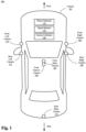
- Fig. 1 illustrates a diagram showing an example autonomous driving system 100 equipped with multiple cameras in accordance with the disclosure. As depicted, the example autonomous driving system 100 may be implemented on a land vehicle 101.
- the example autonomous driving system 100 may include multiple cameras mounted on different locations of the vehicle 101. As described above, the orientations of the cameras may drift due to vibrations, mounting, deformation in the vehicle body. Such drift may occur in three different principal axes or directions, i.e., yaw, pitch, and roll. Contrary to conventional "offline” camera calibration, the present disclosure provides systems and methods for calibrating the cameras while the vehicle is moving. It is noted that the term “online” refers to systems including working components in communication with each other on a traveling vehicle and updating configuration including camera orientations, rather than requiring the support of Internet. In some examples, the term “online” may be used interchangeably with "on-the-fly.”
- the multiple cameras are mounted facing different directions from the perspective of the vehicle 101 and may cover different field-of-view (FOV).
- FOV field-of-view
- a front main camera 102 and a front narrow camera 104 may be both mounted on top of the vehicle 101 facing front.
- the FOV of the front main camera 102 is typically wider than the FOV of the front narrow camera 104.
- Other cameras may be mounted on the side and rear of the vehicle 101 (collectively, “side and rear cameras”).
- a front right camera 106 facing front right and a rear right camera 108 facing rear right may be mounted the right side of the vehicle 101.
- a front left camera 110 facing front left and a rear left camera 112 facing rear left may be mounted on the left side of the vehicle 101.
- a rear main camera 114 facing rear may be mounted on the rear part of the vehicle 101.
- the overlapping FOV between two adjacent cameras may be manually adjusted and set to a predetermined degree.
- the overlapping FOV between the front main camera 102 and the front left camera 110 or the front right camera 106 may be around 28 degrees.
- the overlapping FOV between the front right camera 106 and the rear right camera 108 may be the same as the overlapping FOV between the front left camera 110 and the rear left camera 112. Both may be set to around 28 degrees.
- the overlapping FOV between the rear main camera 114 and the rear left camera 112 or the rear right camera 108 may be around 36 degrees.
- the example autonomous driving system 100 may further include a wheel odometer 116 configured to measure a current speed of the vehicle 101.
- the online calibration in accordance with the present disclosure may include two parts of calibration, i.e., calibrating the front cameras when the vehicle 101 travels at a high speed and calibrating the side and rear cameras when the vehicle 101 travels at a low speed.
- example autonomous driving system 100 may further include a speed monitor 118 configured to determine whether the measured current speed is "high" or "low” according to predetermined speed thresholds.
- the current speed when the current speed is greater than 50km per hour, the current speed may be determined as "high” and when the current speed is less than 30km per hour, the speed may be determined as "low.”
- the result of the speed determination may be sent to a camera calibrator 120 to trigger the calibration process.
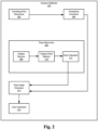
- Fig. 2 illustrates a diagram showing an example camera calibrator 120 for calibrating the multiple cameras of the example autonomous driving system in accordance with the disclosure.
- the camera calibrator 120 may be configured to start the calibration process for the front cameras first.
- the camera calibrator 120 may first check if one or more additional conditions are met prior to the calibration process to ensure the environment surrounding the vehicle 101 is suitable for the calibration process. For example, the camera calibrator 120 may check signals transmitted from other modules of the vehicle 101 via controller area network (CAN) service. The camera calibrator 120 may check the signal from a wiper indicator to determine if the wipers are working, which may indicate whether it is raining. The camera calibrator 120 may check the signal from an angular rater monitor to determine if the angular rate is less than one degree per second, which may indicate whether the vehicle 101 is turning.
- CAN controller area network
- the example autonomous driving system 100 may also include a visual perception system configured to detect lane lines and surrounding objects based on deep learning or artificial intelligence algorithms. Results of the detection may be sent to the camera calibrator 120.
- the camera calibrator 120 may be configured to determine whether the lane lines are straight and whether the vehicle 101 is traveling forward in the middle of the lane lines, e.g., polynomial fitting second order coefficient ⁇ .
- a vanishing point determiner 202 of the camera calibrator 120 may be configured to calculate a convergence of the two lane lines and determine the convergence as the vanishing point of the two lane lines.
- the vanishing point determiner 202 may be configured to periodically calculate multiple vanishing points. Once a count of the multiple vanishing points reaches a preset threshold, the multiple vanishing points may be sent to an orientation calculator 204.
- the orientation calculator 204 may be configured to determine an offset between a predetermined principal point and the vanishing point and further determine a yaw orientation and a pitch orientation based on the offset.
- the yaw and pitch orientations may indicate the amount of the drift of the corresponding camera.
- the example autonomous driving system 100 may be configured to utilize new camera orientation parameters in autonomous driving algorithms accordingly to compensate for the drift.
- the yaw and pitch orientations may be sent to a pose graph generator 214 for further processing.
- the camera calibrator 120 may be configured to start the calibration process for the side and rear cameras subsequent to the calibration of the front cameras if a group of additional conditions are met.
- the camera calibrator 120 may be configured to check the signal from a wiper indicator to determine if the wipers are working, which may indicate whether it is raining.
- the camera calibrator 120 may check the signal from an angular rater monitor to determine if the angular rate is less than one degree per second.
- the camera calibrator 120 may further check the status of low/high/fog beam and the lux of the environment to determine the environmental light is sufficient.
- a pose determiner 206 of the camera calibrator 120 may be configured to determine the relative poses of the multiple side and rear cameras.
- the relative poses of the multiple side and rear cameras may refer to the poses of each camera relative to a reference camera.
- the reference camera may be one of two adjacent cameras having a connecting edge in the pose graph.
- the pose determiner 206 may further include a feature detector 208 configured to detect features of surrounding static objects in images captured by the side and rear cameras.
- a feature point matcher 210 of the pose determiner 206 may be configured to match feature points of a same static object in different images based on ranked similarities.
- a pose calculator 212 of the pose determiner 206 may then be configured to determine the relative poses.
- the pose graph generator 214 may be configured to generate a pose graph with one of the front cameras being set as a reference or an anchor point.
- a loss calculator 216 may be configured to calculate an optimization loss for each of the side and rear cameras based on the pose graph.
- the optimization loss may refer to the orientations that indicate the drifts of the side and rear cameras.
- the example autonomous driving system 100 may be configured to adjust parameters in the autonomous driving algorithms accordingly to compensate for the drifts.
- Fig. 3 illustrates a flow chart showing an example method 300 for calibrating cameras on the example autonomous driving system in accordance with the disclosure.
- the process of performing example method 300 may start from block 302.
- the operations of method 300 may include receiving a current speed of a moving vehicle from a wheel odometer.
- the speed monitor 118 may be configured to receive a current speed of vehicle 101 from the wheel odometer 116.
- the operations of method 300 may include determining that the current speed of the moving vehicle is greater than a first predetermined speed threshold or is less than a second predetermined speed threshold. If the result of the determination of the current speed is greater than the first predetermined speed threshold, the process of the method 300 may continue to block 308. If the result of the determination of the current speed is less than the second predetermined speed threshold but still greater than zero, the process of the method 300 may continue to block 314.
- the operations of method 300 may include checking if a group of first additional conditions are met based on signals fed from a wiper indicator 301, an angular rate monitor 303, and a lane detector 306 via CAN service.
- the camera calibrator 120 may be configured to determine whether it is raining based on the signals from the wiper indicator 301, whether the vehicle 101 is turning based on the signals from the angular rate monitor 303, and whether the lane lines are straight based on the output from the lane detector 306 in the visual perception system.
- the operations of method 300 may include determining the vanishing point by calculating a convergence of the two lane lines on an image plane.
- the vanishing point determiner 202 of the camera calibrator 120 may be configured to calculate a convergence of the two lane lines and determine the convergence as the vanishing point of the two lane lines.
- the vanishing point determiner 202 may be configured to periodically calculate multiple vanishing points. Once a count of the multiple vanishing points reaches a preset threshold, the multiple vanishing points may be sent to the orientation calculator 204.
- the operations of method 300 may include calculating a yaw orientation and a pitch orientation respectively for the at least one front camera based on a difference between the vanishing point and a principal point and calibrating the front cameras.
- the orientation calculator 204 may be configured to determine an offset between a predetermined principal point and the vanishing point and further determine a yaw orientation and a pitch orientation based on the offset. The process of method 300 may continue to block 314.
- the operations of method 300 may include determining a group of second additional conditions are met.
- the camera calibrator 120 may be configured to check the signal from a wiper indicator to determine if the wipers are working and if it is raining.
- the camera calibrator 120 may check the signal from an angular rater monitor to determine if the angular rate is less than one degree per second.
- the camera calibrator 120 may further check the status of low/high/fog beam and the lux of the environment to determine the environmental light is sufficient.
- the operations of method 300 may include determining the relative poses of the multiple side and rear cameras.
- a pose determiner 206 of the camera calibrator 120 may be configured to determine the relative poses of the multiple side and rear cameras.
- the operations of method 300 may include generating the pose graph that includes the relative poses of the multiple side and rear cameras.
- the pose graph generator 214 may be configured to generate a pose graph with one of the front cameras being set as a reference or an anchor point.
- the operations of method 300 may include calculating an optimization loss for each of the multiple side and rear cameras based on the pose graph.
- the loss calculator 216 may be configured to calculate an optimization loss for each of the side and rear cameras based on the pose graph.
- Fig. 4 illustrates a diagram showing an example vanishing point in accordance with the disclosure.
- the vanishing point may be defined as a point on the image plane representing the converge of 2D perspective projections of mutually parallel lines in 3D space. Specifically, the vanishing point is an infinity point independent of translation T in the 3D coordinate.
- VP 2d refers to the position of the vanishing point in the 2D image
- VP 3d refers to the 3D coordinate of the vanishing point.
- the vanishing point may correspond to the yaw and pitch orientation of the front camera.
- the principal point is typically provided in camera intrinsic information and is determined when a camera is produced.
- Fig. 5 illustrate a flow chart showing an example method 500 for determining relative poses of multiple side and rear cameras in accordance with the disclosure.
- the process of determining or estimating relative poses of the side and rear cameras may be performed based the overlapping FOV between two adjacent cameras, for example, the overlapping FOV between the front main camera 102 and the front right camera 106. Images captured by the two adjacent cameras may be provided at the beginning of the process of method 500 for determining the relative poses. Dash-lined blocks may indicate optional operations of method 500.
- the operations of method 500 may include detecting features of objects in images captured by the multiple side and rear cameras.
- the feature detector 208 may be configured to detect the features of surrounding static objects in accordance with some existing algorithm, e.g., a scale-invariant feature transform (SIFT) algorithm.
- SIFT scale-invariant feature transform
- the feature points of moving objects may be removed.
- the moving objects in the images may then be marked with bounding boxes. In other words, features points in the bounding boxes may not be considered in later process.
- the operations of method 500 may include matching feature points in the images based on ranked similarities.
- the feature point matcher 210 may be configured to match the feature points in different images captured by the two adjacent cameras and rank the feature points based on the similarities of the feature points.
- the ranking may be performed by the feature point matcher 210 in accordance with a k-nearest-neighbor (KNN) algorithm.
- KNN k-nearest-neighbor
- the feature point matcher 210 may be further configured to filter and discard unqualified feature points.
- the filtering may include one or more phases, e.g., distance filtering, symmetric filtering, and nominal extrinsic filtering.
- distance filtering the feature point matcher 210 may be configured to discard two similar points that are too close.
- symmetric filtering the feature point matcher 210 may be configured to discard feature points that only can be projected from one image to the other, but not vice versa.
- nominal extrinsic filtering the feature point matcher 210 may be configured to discard feature points based on point correspondences between two cameras that are constrained by initial camera setup including camera translation relative to vehicle and camera ideal installation orientation angles. Feature points that meet the criteria will be kept.
- the criteria can be formulated as x 1 T t ⁇ Rx 2 ⁇ ⁇ , where x 1 and x 2 are normalized corresponding points from two images captured by two adjacent cameras, t and R are the ideal installation translation and rotation, and ⁇ is a predetermined threshold value.
- the operations of method 500 may include determining relative poses based on the matched feature points.
- the pose calculator 212 may be configured to estimate or determine the relative pose of each camera taking an adjacent camera as a reference point.
- the pose calculator 212 may be configured to calculate an essential matrix between the two adjacent cameras and decompose the essential matrix into a rotation and a translation matrix as the relative pose.
- the operations of method 500 may include rejecting unqualified relative poses.
- the relative poses may be discarded and rejected as invalid by the pose calculator 212.
- a reprojection error may refer to a geometric error when projecting a point from one image to another image using estimated relative pose. The average error of all matching points should be smaller than a predetermined threshold. Otherwise, this estimated relative pose may be rejected.
- each point depth (distance) can be calculated based on estimated relative pose. The standard deviation of the depth distribution formed by all matching points should be larger than a predefined threshold. Otherwise, this estimated relative pose is rejected.
- the operations of method 500 may include outputting valid relative poses.
- the pose calculator 212 may be configured to output the valid relative poses to the pose graph generator 214.
- Fig. 6 illustrates a diagram showing an example process for determining optimization losses of the multiple side and rear cameras in accordance with the disclosure.
- the loss calculator 216 may be configured to generate a pose graph with each of the six cameras being vertices and the relative poses (e.g., R 1 to R 6 as shown) between any two adjacent cameras being edges.
- Adjacent cameras may refer to a pair of cameras that are connected by an edge on the pose graph (e.g., the front right camera 106 and the rear right camera 108). Since the front main camera 102 has been calibrated prior to other side and rear cameras, the front main camera 102 may be set as the anchor point.
- the pose graph may also be applied to calibrate one or two cameras if other cameras are well calibrated.
- Fig. 7 illustrates a diagram showing another example process for calibrating the multiple cameras in accordance with the disclosure.
- a camera image stream 702 may be fed to one or more memory ring buffers 704 respectively for each camera.
- the memory ring buffers 704 may temporarily store the camera image stream 702 and feed the camera image stream 702 to a vehicle perception system 720 (alternatively, "visual perception system" as described above).
- the vehicle perception system 720 may be configured to detect or recognize static objects in the camera image stream 702 including lane lines.
- the detected static objects may be transmitted to the pose determiner 206, e.g., block 710.
- moving objects may be detected but marked with bounding boxes such that the feature points within the bounding boxes will not be considered as input for the feature point matcher 210.
- the camera calibrator 120 may be configured to check lane lines straightness (block 722) and other signals via CAN service 708. For example, the camera calibrator 120 may be configured to determine whether it is raining based on the signals from the wiper indicator 301, whether the vehicle 101 is turning based on the signals from the angular rate monitor 303, and whether the lane lines are straight based on the output from the lane detector 306 in the visual perception system.
- the vanishing point determiner 202 of the camera calibrator 120 may be configured to calculate a convergence of the two lane lines and determine the convergence as the vanishing point of the two lane lines. Further, at block 728, when a count of collected vanishing points, e.g., stored by a vanishing point counter 724, is greater than a preset threshold, e.g., N H , a histogram may be created and the peak value of the histogram may be selected as the rotation angle for the final calibration results as indicated by block 730.
- the calibration results may be sent to a calibration file management system 732 that manages the calibration configuration files of cameras of the example autonomous driving system 100. In some examples, when camera calibrator 120 sends the latest calibrated camera orientations to the file management system 732, the file management system 732 may update the camera configuration files and notify other modules of the autonomous driving system 100.
- the camera calibrator 120 may similarly check if additional conditions are met based on signals transmitted via CAN service 708.
- the camera calibrator 120 may be configured to check the signal from a wiper indicator to determine if the wipers are working and if it is raining.
- the camera calibrator 120 may check the signal from an angular rater monitor to determine if the angular rate is less than one degree per second.
- the camera calibrator 120 may further check the status of low/high/fog beam and the lux of the environment to determine the environmental light is sufficient.
- the camera calibrator 120 may be configured to identify pairs of images taken by two adjacent cameras from the memory ring buffer 704.
- the feature detector 208 may be configured to detect the features of surrounding static objects in accordance with some existing algorithm, e.g., a scale-invariant feature transform (SIFT) algorithm.
- SIFT scale-invariant feature transform
- the feature point matcher 210 may be configured to match the feature points in different images captured by the two adjacent cameras and rank the feature points based on the similarities of the feature points.
- the pose calculator 212 may be configured to check an edge counter 712 that stores a count of estimated relative poses.
- the pose graph generator 214 may be configured to generate the pose graph.
- the loss calculator 216 may be configured to calculate an optimization loss for each of the side and rear cameras based on the pose graph.
- the calibration results may also be sent to a calibration file management system 732.
- the process and method as depicted in the foregoing drawings may be executed through processing logics including hardware (e.g., circuit, special logic, etc .), firmware, software (e.g., a software embodied in a non-transient computer readable medium), or combination of each two.
- processing logics including hardware (e.g., circuit, special logic, etc .), firmware, software (e.g., a software embodied in a non-transient computer readable medium), or combination of each two.
- the term "or” is intended to mean an inclusive “or” rather than an exclusive “or.” That is, unless specified otherwise, or clear from the context, the phrase “X employs A or B” is intended to mean any of the natural inclusive permutations. That is, the phrase “X employs A or B” is satisfied by any of the following instances: X employs A; X employs B; or X employs both A and B.
- the articles “a” and “an” as used in this application and the appended claims should generally be construed to mean “one or more” unless specified otherwise or clear from the context to be directed to a singular form.
Landscapes
- Engineering & Computer Science (AREA)
- Computer Vision & Pattern Recognition (AREA)
- Physics & Mathematics (AREA)
- General Physics & Mathematics (AREA)
- Theoretical Computer Science (AREA)
- Automation & Control Theory (AREA)
- Multimedia (AREA)
- Signal Processing (AREA)
- General Health & Medical Sciences (AREA)
- Biomedical Technology (AREA)
- Health & Medical Sciences (AREA)
- Human Computer Interaction (AREA)
- Transportation (AREA)
- Mechanical Engineering (AREA)
- Traffic Control Systems (AREA)
- Studio Devices (AREA)
- Image Analysis (AREA)
Claims (15)
- Verfahren zum Kalibrieren von Kameras in einem autonomen Fahrsystem, umfassend:Empfangen einer momentanen Geschwindigkeit eines sich bewegenden Fahrzeugs von einem Radkilometerzähler; Bestimmen, dass die momentane Geschwindigkeit des sich bewegenden Fahrzeugs größer ist als eine erste zuvor festgelegte Geschwindigkeitsschwelle;Kalibrieren, auf der Grundlage der Bestimmung, dass die momentane Geschwindigkeit größer ist als die zuvor festgelegte Geschwindigkeitsschwelle, mindestens einer Frontkamera des sich bewegenden Fahrzeugs gemäß einer Position eines Fluchtpunkts zweier Fahrspurlinien;Bestimmen, dass die momentane Geschwindigkeit des sich bewegenden Fahrzeugs kleiner als eine zweite zuvor festgelegte Geschwindigkeitsschwelle ist und größer als null ist; undKalibrieren, auf der Grundlage der Bestimmung, dass die momentane Geschwindigkeit kleiner als die zuvor festgelegte Geschwindigkeitsschwelle ist und größer als null ist, mehrerer Seiten- und Heckkameras des sich bewegenden Fahrzeugs gemäß einem Lagegraphen, der relative Lagen der mehreren Seiten- und Heckkameras enthält.
- Verfahren zum Kalibrieren von Kameras in dem autonomen Fahrsystem von Anspruch 1, des Weiteren umfassend:
vor dem Kalibrieren der mindestens einen Frontkamera, Bestimmen, dass eine Gruppe erster zusätzlicher Bedingungen erfüllt ist, wobei die Gruppe erster zusätzlicher Bedingungen einen Scheibenwischerindikator, der keinen Regen zeigt, einen Winkelgeschwindigkeitsmonitor, der zeigt, dass eine momentane Winkelgeschwindigkeit weniger als ein Grad pro Sekunde beträgt, und dass die Fahrspurlinien als gerade bestimmt sind, enthält. - Verfahren zum Kalibrieren von Kameras in dem autonomen Fahrsystem von Anspruch 1, des Weiteren umfassend:
vor dem Kalibrieren der mehreren Seiten- und Heckkameras, Bestimmen, dass eine Gruppe zweiter zusätzlicher Bedingungen erfüllt ist, wobei die Gruppe zweiter zusätzlicher Bedingungen einen Scheibenwischerindikator, der keinen Regen zeigt, einen Lichtsensor und einen Strahlindikator, die ausreichendes Umgebungslicht zeigen, und einen Winkelgeschwindigkeitsmonitor, der zeigt, dass eine momentane Winkelgeschwindigkeit weniger als ein Grad pro Sekunde beträgt, enthält. - Verfahren zum Kalibrieren von Kameras in dem autonomen Fahrsystem von Anspruch 1, wobei die mindestens eine Frontkamera eine vordere Hauptkamera und eine vordere schmale Kamera aufweist, die beide auf einem Verdeck des sich bewegenden Fahrzeugs montiert sind.
- Verfahren zum Kalibrieren von Kameras in dem autonomen Fahrsystem von Anspruch 1, wobei das Kalibrieren der mindestens einen Frontkamera des Weiteren aufweist:Bestimmen des Fluchtpunktes durch Berechnen einer Konvergenz der beiden Fahrspurlinien auf einer Bildebene;
undBerechnen einer Gierausrichtung bzw einer Nickausrichtung für die mindestens eine Frontkamera auf der Grundlage einer Differenz zwischen dem Fluchtpunkt und einem Hauptpunkt. - Verfahren zum Kalibrieren von Kameras in dem autonomen Fahrsystem von Anspruch 1, wobei das Kalibrieren der mehreren Seiten- und Heckkameras des sich bewegenden Fahrzeugs des Weiteren umfasst:Bestimmen der relativen Lagen der mehreren Seiten- und Heckkameras;Generieren des Lagegraphen, der die relativen Lagen der mehreren Seiten- und Heckkameras enthält; und Berechnen eines Optimierungsverlustes für jede der mehreren Seiten- und Heckkameras auf der Grundlage des Lagegraphen.
- Verfahren zum Kalibrieren von Kameras in dem autonomen Fahrsystem von Anspruch 6, wobei das Bestimmen der relativen Lagen der mehreren Seiten- und Heckkameras des Weiteren aufweist:Detektieren von Merkmalen von Objekten in Bildern, die durch die mehreren Seiten- und Heckkameras aufgenommen wurden;Abgleichen von Merkmalspunkten in den Bildern auf der Grundlage von ranggeordneten Ähnlichkeiten; undBestimmen der relativen Lagen auf der Grundlage der abgeglichenen Merkmalspunkte.
- Verfahren zum Kalibrieren von Kameras in dem autonomen Fahrsystem von Anspruch 7, wobei die Merkmale der Objekte durch einen Algorithmus zur skaleninvarianten Merkmalstransformation (SIFT) detektiert werden.
- Verfahren zum Kalibrieren von Kameras in dem autonomen Fahrsystem von Anspruch 7, wobei Ähnlichkeiten der Merkmalspunkte in den Bildern durch einen k-Nearest-Neighbor-Algorithmus (KNN) ranggeordnet werden.
- Verfahren zum Kalibrieren von Kameras in dem autonomen Fahrsystem von Anspruch 7, wobei das Bestimmen der relativen Lagen des Weiteren das Berechnen einer Essential-Matrix zweier benachbarter Kameras und das Zerlegen der Essential-Matrix in eine Rotations- und Translationsmatrix, um eine der relativen Lagen zu sein, umfasst.
- System zum Kalibrieren von Kameras in einem autonomen Fahrsystem, umfassend:einen Radkilometerzähler, der dazu eingerichtet ist, eine momentane Geschwindigkeit eines sich bewegenden Fahrzeugs zu messen;einen Geschwindigkeitsmonitor, der dazu eingerichtet ist zu bestimmen, dass die momentane Geschwindigkeit des sich bewegenden Fahrzeugs größer ist als eine erste zuvor festgelegte Geschwindigkeitsschwelle; undeinen Kamerakalibrator, der dazu eingerichtet ist, auf der Grundlage der Bestimmung, dass die momentane Geschwindigkeit größer ist als die zuvor festgelegte Geschwindigkeitsschwelle, mindestens einer Frontkamera des sich bewegenden Fahrzeugs gemäß einer Position eines Fluchtpunkts zweier Fahrspurlinien zu kalibrieren,wobei der Geschwindigkeitsmonitor des Weiteren dazu eingerichtet ist zu bestimmen, dass die momentane Geschwindigkeit des sich bewegenden Fahrzeugs kleiner als eine zweite zuvor festgelegte Geschwindigkeitsschwelle ist und größer als null ist, undwobei der Kamerakalibrator des Weiteren dazu eingerichtet ist, auf der Grundlage der Bestimmung, dass die momentane Geschwindigkeit kleiner als die zuvor festgelegte Geschwindigkeitsschwelle ist und größer als null ist, mehrere Seiten- und Heckkameras des sich bewegenden Fahrzeugs gemäß einem Lagegraphen, der relative Lagen der mehreren Seiten- und Heckkameras enthält, zu kalibrieren.
- System zum Kalibrieren von Kameras in dem autonomen Fahrsystem von Anspruch 11, wobei der Kamerakalibrator des Weiteren dazu eingerichtet ist, vor dem Kalibrieren der mindestens einen Frontkamera:auf der Grundlage von Signalen von einem Scheibenwischerindikator "kein Regen" zu bestimmen;auf der Grundlage von Signalen von einem Winkelgeschwindigkeitsmonitor zu bestimmen, dass eine momentane Winkelgeschwindigkeit weniger als ein Grad pro Sekunde beträgt; undauf der Grundlage von Bildern, die durch die mindestens eine Frontkamera aufgenommen wurden, zu bestimmen, dass die Fahrspurlinien gerade sind,
oderwobei der Kamerakalibrator des Weiteren dazu eingerichtet ist, vor dem Kalibrieren der mehreren Seiten- und Heckseitenkameras:auf der Grundlage von Signalen von einem Scheibenwischerindikator "kein Regen" zu bestimmen;auf der Grundlage eines Lichtsensors und eines Strahlindikators zu bestimmen, dass das Umgebungslicht ausreichend ist; undauf der Grundlage von Signalen von einem Winkelgeschwindigkeitsmonitor zu bestimmen, dass eine momentane Winkelgeschwindigkeit weniger als ein Grad pro Sekunde beträgt,
oderwobei die mindestens eine Frontkamera eine vordere Hauptkamera und eine vordere schmale Kamera umfasst, die beide auf einer Oberseite des sich bewegenden Fahrzeugs montiert sind,
oderwobei der Kamerakalibrator aufweist:einen Fluchtpunktbestimmer, der dazu eingerichtet ist, eine Konvergenz der zwei Fahrspurlinien auf einer Bildebene zu berechnen; undeinen Orientierungsberechner, der dazu eingerichtet ist, eine Gierausrichtung bzw einer Nickausrichtung für die mindestens eine Frontkamera auf der Grundlage einer Differenz zwischen dem Fluchtpunkt und einem Hauptpunkt zu berechnen. - System zum Kalibrieren von Kameras in dem autonomen Fahrsystem von Anspruch 11, wobei der Kamerakalibrator aufweist:einen Lagebestimmer, der dazu eingerichtet ist, die relativen Lagen der mehreren Seiten- und Heckkameras zu bestimmen;einen Lagegraphengenerator, der dazu eingerichtet ist, den Lagegraphen zu generieren, der die relativen Lagen der mehreren Seiten- und Heckkameras enthält; und einen Verlustberechner, der dazu eingerichtet ist, einen Optimierungsverlust für jede der mehreren Seiten- und Heckkameras auf der Grundlage des Lagegraphen zu berechnen.
- System zum Kalibrieren von Kameras in dem autonomen Fahrsystem von Anspruch 13, wobei der Lagebestimmer des Weiteren aufweist:einen Merkmalsdetektor, der dazu eingerichtet ist, Merkmale von Objekten in Bildern, die durch die mehreren Seiten- und Heckkameras aufgenommen wurden, zu detektieren;einen Merkmalspunktabgleicher, der dazu eingerichtet ist, Merkmalspunkte in den Bildern auf der Grundlage von ranggeordneten Ähnlichkeiten abzugleichen; und einen Lageberechner, der dazu eingerichtet ist, die relativen Lagen auf der Grundlage der abgeglichenen Merkmalspunkte zu bestimmen.
- System zum Kalibrieren von Kameras in dem autonomen Fahrsystem von Anspruch 14, wobei der Merkmalsdetektor dazu eingerichtet ist, die Merkmale der Objekte durch einen Algorithmus der skaleninvarianten Merkmalstransformation (SIFT) zu detektieren,
oderwobei der Merkmalspunktabgleicher des Weiteren dazu eingerichtet ist, Ähnlichkeiten der Merkmalspunkte in den Bildern durch einen k-Nearest-Neighbor-Algorithmus (KNN) rangzuordnen,
oderwobei der Lageberechner des Weiteren dazu eingerichtet ist, eine Essential-Matrix zweier benachbarter Kameras zu berechnen und die Essential-Matrix in eine Rotations- und Translationsmatrix zu zerlegen, um eine der relativen Lagen zu sein.
Applications Claiming Priority (1)
| Application Number | Priority Date | Filing Date | Title |
|---|---|---|---|
| US17/936,092 US12200186B2 (en) | 2022-09-28 | 2022-09-28 | System, method and software for online camera calibration in vehicles based on vanishing point and pose graph |
Publications (3)
| Publication Number | Publication Date |
|---|---|
| EP4345751A1 EP4345751A1 (de) | 2024-04-03 |
| EP4345751C0 EP4345751C0 (de) | 2025-06-18 |
| EP4345751B1 true EP4345751B1 (de) | 2025-06-18 |
Family
ID=84766978
Family Applications (1)
| Application Number | Title | Priority Date | Filing Date |
|---|---|---|---|
| EP22217250.4A Active EP4345751B1 (de) | 2022-09-28 | 2022-12-30 | System und verfahren zur online-kamerakalibrierung in fahrzeugen auf basis von fluchtpunkt und posengraph |
Country Status (3)
| Country | Link |
|---|---|
| US (1) | US12200186B2 (de) |
| EP (1) | EP4345751B1 (de) |
| CN (1) | CN116188580B (de) |
Families Citing this family (5)
| Publication number | Priority date | Publication date | Assignee | Title |
|---|---|---|---|---|
| US9557736B1 (en) * | 2015-04-08 | 2017-01-31 | Google Inc. | Detecting street parked vehicles |
| JPWO2022219862A1 (de) * | 2021-04-15 | 2022-10-20 | ||
| EP4383199A4 (de) * | 2021-08-06 | 2025-07-23 | Obshchestvo S Ogranichennoi Otvetstvennostiu Evokargo | Verfahren zur kalibrierung extrinsischer videokameraparameter |
| KR20240030098A (ko) * | 2022-08-29 | 2024-03-07 | 현대자동차주식회사 | 차량 및 차량의 제어 방법 |
| US12405116B2 (en) * | 2023-03-03 | 2025-09-02 | Telenav, Inc. | Navigation system with automatic optical calibration mechanism and method of operation thereof |
Family Cites Families (12)
| Publication number | Priority date | Publication date | Assignee | Title |
|---|---|---|---|---|
| US9834153B2 (en) * | 2011-04-25 | 2017-12-05 | Magna Electronics Inc. | Method and system for dynamically calibrating vehicular cameras |
| EP2858035B1 (de) * | 2013-10-01 | 2020-04-22 | Application Solutions (Electronics and Vision) Limited | System, Fahrzeug und Verfahren zur Online-Kalibrierung einer Kamera an einem Fahrzeug |
| WO2019094843A1 (en) * | 2017-11-10 | 2019-05-16 | Nvidia Corporation | Systems and methods for safe and reliable autonomous vehicles |
| DE102017222135A1 (de) * | 2017-12-07 | 2019-06-13 | Robert Bosch Gmbh | System und Verfahren zum Ausrichten einer Kalibriervorrichtung zum Kalibrieren von Fahrzeugumfeldsensoren |
| US10545506B2 (en) * | 2018-02-14 | 2020-01-28 | Ford Global Technologies, Llc | Methods and apparatus to perform visual odometry using a vehicle camera system |
| DE102019220049A1 (de) * | 2019-12-18 | 2021-06-24 | Robert Bosch Gmbh | Verfahren und Vorrichtung zur Kalibrierung mindestens eines Sensors |
| CN112689588B (zh) * | 2019-12-24 | 2022-02-18 | 华为技术有限公司 | 一种自动驾驶车辆的控制方法及装置 |
| US11348278B2 (en) * | 2020-09-10 | 2022-05-31 | Ford Global Technologies, Llc | Object detection |
| CN112146682B (zh) * | 2020-09-22 | 2022-07-19 | 福建牧月科技有限公司 | 智能汽车的传感器标定方法、装置、电子设备及介质 |
| CN112183512B (zh) * | 2020-12-02 | 2021-11-19 | 深圳佑驾创新科技有限公司 | 摄像头标定方法、装置、车载终端和存储介质 |
| US11474193B2 (en) * | 2020-12-09 | 2022-10-18 | Here Global B.V. | Camera calibration for localization |
| CN114494456B (zh) * | 2022-01-11 | 2025-04-25 | 上海交通大学 | 基于移动标定板多相机外参标定方法、系统、介质及终端 |
-
2022
- 2022-09-28 US US17/936,092 patent/US12200186B2/en active Active
- 2022-12-30 EP EP22217250.4A patent/EP4345751B1/de active Active
-
2023
- 2023-02-24 CN CN202310172928.7A patent/CN116188580B/zh active Active
Also Published As
| Publication number | Publication date |
|---|---|
| CN116188580A (zh) | 2023-05-30 |
| US20240107001A1 (en) | 2024-03-28 |
| EP4345751C0 (de) | 2025-06-18 |
| CN116188580B (zh) | 2026-02-10 |
| US12200186B2 (en) | 2025-01-14 |
| EP4345751A1 (de) | 2024-04-03 |
Similar Documents
| Publication | Publication Date | Title |
|---|---|---|
| EP4345751B1 (de) | System und verfahren zur online-kamerakalibrierung in fahrzeugen auf basis von fluchtpunkt und posengraph | |
| CN110745140B (zh) | 一种基于连续图像约束位姿估计的车辆换道预警方法 | |
| US10726576B2 (en) | System and method for identifying a camera pose of a forward facing camera in a vehicle | |
| EP3505865B1 (de) | Fahrzeuginterne kamera, verfahren zur einstellung der fahrzeuginternen kamera und fahrzeuginternes kamerasystem | |
| US10424081B2 (en) | Method and apparatus for calibrating a camera system of a motor vehicle | |
| CA2975139C (en) | Stereo camera system for collision avoidance during aircraft surface operations | |
| US6812831B2 (en) | Vehicle surroundings monitoring apparatus | |
| EP3678096A1 (de) | Verfahren zur berechnung einer anhängerkupplungsposition | |
| US20180313942A1 (en) | Calibration of laser sensors | |
| JP6565769B2 (ja) | 車載カメラの取付角度検出装置、取付角度較正装置、取付角度検出方法、取付角度較正方法、およびコンピュータープログラム | |
| EP3070675B1 (de) | Bildprozessor, fotografievorrichtung, programm, vorrichtungssteuerungssystem und vorrichtung | |
| EP3615955A1 (de) | Kalibrierung von laser- und sichtsensoren | |
| US11431958B2 (en) | Vision system and method for a motor vehicle | |
| CN106054191A (zh) | 车轮检测和其在物体跟踪以及传感器配准中的应用 | |
| WO2014199929A1 (ja) | 単眼モーションステレオ距離推定方法および単眼モーションステレオ距離推定装置 | |
| US20190362512A1 (en) | Method and Apparatus for Estimating a Range of a Moving Object | |
| US9892519B2 (en) | Method for detecting an object in an environmental region of a motor vehicle, driver assistance system and motor vehicle | |
| CN113177976A (zh) | 一种深度估计方法、装置、电子设备及存储介质 | |
| US10706586B2 (en) | Vision system for a motor vehicle and method of controlling a vision system | |
| US11477371B2 (en) | Partial image generating device, storage medium storing computer program for partial image generation and partial image generating method | |
| EP3486871B1 (de) | Bildsystem und verfahren zum autonomen fahren und/oder zur fahrerassistenz in einem kraftfahrzeug | |
| WO2021056283A1 (en) | Systems and methods for adjusting a vehicle pose | |
| US10249056B2 (en) | Vehicle position estimation system | |
| US10643077B2 (en) | Image processing device, imaging device, equipment control system, equipment, image processing method, and recording medium storing program | |
| US20230421739A1 (en) | Robust Stereo Camera Image Processing Method and System |
Legal Events
| Date | Code | Title | Description |
|---|---|---|---|
| PUAI | Public reference made under article 153(3) epc to a published international application that has entered the european phase |
Free format text: ORIGINAL CODE: 0009012 |
|
| STAA | Information on the status of an ep patent application or granted ep patent |
Free format text: STATUS: THE APPLICATION HAS BEEN PUBLISHED |
|
| AK | Designated contracting states |
Kind code of ref document: A1 Designated state(s): AL AT BE BG CH CY CZ DE DK EE ES FI FR GB GR HR HU IE IS IT LI LT LU LV MC ME MK MT NL NO PL PT RO RS SE SI SK SM TR |
|
| STAA | Information on the status of an ep patent application or granted ep patent |
Free format text: STATUS: REQUEST FOR EXAMINATION WAS MADE |
|
| 17P | Request for examination filed |
Effective date: 20241002 |
|
| RBV | Designated contracting states (corrected) |
Designated state(s): AL AT BE BG CH CY CZ DE DK EE ES FI FR GB GR HR HU IE IS IT LI LT LU LV MC ME MK MT NL NO PL PT RO RS SE SI SK SM TR |
|
| GRAP | Despatch of communication of intention to grant a patent |
Free format text: ORIGINAL CODE: EPIDOSNIGR1 |
|
| STAA | Information on the status of an ep patent application or granted ep patent |
Free format text: STATUS: GRANT OF PATENT IS INTENDED |
|
| INTG | Intention to grant announced |
Effective date: 20250207 |
|
| GRAS | Grant fee paid |
Free format text: ORIGINAL CODE: EPIDOSNIGR3 |
|
| GRAA | (expected) grant |
Free format text: ORIGINAL CODE: 0009210 |
|
| STAA | Information on the status of an ep patent application or granted ep patent |
Free format text: STATUS: THE PATENT HAS BEEN GRANTED |
|
| AK | Designated contracting states |
Kind code of ref document: B1 Designated state(s): AL AT BE BG CH CY CZ DE DK EE ES FI FR GB GR HR HU IE IS IT LI LT LU LV MC ME MK MT NL NO PL PT RO RS SE SI SK SM TR |
|
| REG | Reference to a national code |
Ref country code: GB Ref legal event code: FG4D |
|
| REG | Reference to a national code |
Ref country code: CH Ref legal event code: EP |
|
| REG | Reference to a national code |
Ref country code: DE Ref legal event code: R096 Ref document number: 602022016068 Country of ref document: DE |
|
| REG | Reference to a national code |
Ref country code: CH Ref legal event code: EP |
|
| REG | Reference to a national code |
Ref country code: IE Ref legal event code: FG4D |
|
| U01 | Request for unitary effect filed |
Effective date: 20250618 |
|
| U07 | Unitary effect registered |
Designated state(s): AT BE BG DE DK EE FI FR IT LT LU LV MT NL PT RO SE SI Effective date: 20250627 |
|
| PG25 | Lapsed in a contracting state [announced via postgrant information from national office to epo] |
Ref country code: NO Free format text: LAPSE BECAUSE OF FAILURE TO SUBMIT A TRANSLATION OF THE DESCRIPTION OR TO PAY THE FEE WITHIN THE PRESCRIBED TIME-LIMIT Effective date: 20250918 Ref country code: GR Free format text: LAPSE BECAUSE OF FAILURE TO SUBMIT A TRANSLATION OF THE DESCRIPTION OR TO PAY THE FEE WITHIN THE PRESCRIBED TIME-LIMIT Effective date: 20250919 |
|
| PG25 | Lapsed in a contracting state [announced via postgrant information from national office to epo] |
Ref country code: HR Free format text: LAPSE BECAUSE OF FAILURE TO SUBMIT A TRANSLATION OF THE DESCRIPTION OR TO PAY THE FEE WITHIN THE PRESCRIBED TIME-LIMIT Effective date: 20250618 |
|
| PG25 | Lapsed in a contracting state [announced via postgrant information from national office to epo] |
Ref country code: RS Free format text: LAPSE BECAUSE OF FAILURE TO SUBMIT A TRANSLATION OF THE DESCRIPTION OR TO PAY THE FEE WITHIN THE PRESCRIBED TIME-LIMIT Effective date: 20250918 |
|
| U20 | Renewal fee for the european patent with unitary effect paid |
Year of fee payment: 4 Effective date: 20251124 |
|
| PG25 | Lapsed in a contracting state [announced via postgrant information from national office to epo] |
Ref country code: IS Free format text: LAPSE BECAUSE OF FAILURE TO SUBMIT A TRANSLATION OF THE DESCRIPTION OR TO PAY THE FEE WITHIN THE PRESCRIBED TIME-LIMIT Effective date: 20251018 |
|
| PG25 | Lapsed in a contracting state [announced via postgrant information from national office to epo] |
Ref country code: SM Free format text: LAPSE BECAUSE OF FAILURE TO SUBMIT A TRANSLATION OF THE DESCRIPTION OR TO PAY THE FEE WITHIN THE PRESCRIBED TIME-LIMIT Effective date: 20250618 |
|
| PG25 | Lapsed in a contracting state [announced via postgrant information from national office to epo] |
Ref country code: CZ Free format text: LAPSE BECAUSE OF FAILURE TO SUBMIT A TRANSLATION OF THE DESCRIPTION OR TO PAY THE FEE WITHIN THE PRESCRIBED TIME-LIMIT Effective date: 20250618 |
|
| PG25 | Lapsed in a contracting state [announced via postgrant information from national office to epo] |
Ref country code: PL Free format text: LAPSE BECAUSE OF FAILURE TO SUBMIT A TRANSLATION OF THE DESCRIPTION OR TO PAY THE FEE WITHIN THE PRESCRIBED TIME-LIMIT Effective date: 20250618 |
|
| PG25 | Lapsed in a contracting state [announced via postgrant information from national office to epo] |
Ref country code: SK Free format text: LAPSE BECAUSE OF FAILURE TO SUBMIT A TRANSLATION OF THE DESCRIPTION OR TO PAY THE FEE WITHIN THE PRESCRIBED TIME-LIMIT Effective date: 20250618 |
|
| PG25 | Lapsed in a contracting state [announced via postgrant information from national office to epo] |
Ref country code: ES Free format text: LAPSE BECAUSE OF FAILURE TO SUBMIT A TRANSLATION OF THE DESCRIPTION OR TO PAY THE FEE WITHIN THE PRESCRIBED TIME-LIMIT Effective date: 20250618 |
|
| PLBE | No opposition filed within time limit |
Free format text: ORIGINAL CODE: 0009261 |
|
| STAA | Information on the status of an ep patent application or granted ep patent |
Free format text: STATUS: NO OPPOSITION FILED WITHIN TIME LIMIT |