EP4345399A1 - Récepteur solaire pour applications à haute température - Google Patents
Récepteur solaire pour applications à haute température Download PDFInfo
- Publication number
- EP4345399A1 EP4345399A1 EP22198281.2A EP22198281A EP4345399A1 EP 4345399 A1 EP4345399 A1 EP 4345399A1 EP 22198281 A EP22198281 A EP 22198281A EP 4345399 A1 EP4345399 A1 EP 4345399A1
- Authority
- EP
- European Patent Office
- Prior art keywords
- window
- fluid
- cooling liquid
- solar
- conduit
- Prior art date
- Legal status (The legal status is an assumption and is not a legal conclusion. Google has not performed a legal analysis and makes no representation as to the accuracy of the status listed.)
- Pending
Links
- 239000012530 fluid Substances 0.000 claims abstract description 222
- 239000000110 cooling liquid Substances 0.000 claims abstract description 141
- 239000013529 heat transfer fluid Substances 0.000 claims abstract description 73
- 239000007788 liquid Substances 0.000 claims abstract description 73
- 238000001816 cooling Methods 0.000 claims abstract description 53
- 230000005855 radiation Effects 0.000 claims abstract description 48
- 239000010410 layer Substances 0.000 claims description 82
- 229910001868 water Inorganic materials 0.000 claims description 39
- XLYOFNOQVPJJNP-UHFFFAOYSA-N water Substances O XLYOFNOQVPJJNP-UHFFFAOYSA-N 0.000 claims description 38
- 238000000034 method Methods 0.000 claims description 35
- 230000008569 process Effects 0.000 claims description 23
- 238000006243 chemical reaction Methods 0.000 claims description 18
- 238000004519 manufacturing process Methods 0.000 claims description 16
- 239000004568 cement Substances 0.000 claims description 14
- 230000003595 spectral effect Effects 0.000 claims description 14
- 238000005507 spraying Methods 0.000 claims description 11
- 239000000126 substance Substances 0.000 claims description 10
- 238000002834 transmittance Methods 0.000 claims description 10
- 239000000446 fuel Substances 0.000 claims description 7
- 238000012545 processing Methods 0.000 claims description 7
- 150000001875 compounds Chemical class 0.000 claims description 6
- 239000000376 reactant Substances 0.000 claims description 6
- 239000002356 single layer Substances 0.000 claims description 6
- 239000007921 spray Substances 0.000 claims description 6
- 229910052751 metal Inorganic materials 0.000 claims description 5
- 239000002184 metal Substances 0.000 claims description 5
- 150000002739 metals Chemical class 0.000 claims description 4
- 239000006096 absorbing agent Substances 0.000 description 19
- CURLTUGMZLYLDI-UHFFFAOYSA-N Carbon dioxide Chemical compound O=C=O CURLTUGMZLYLDI-UHFFFAOYSA-N 0.000 description 16
- 229910002092 carbon dioxide Inorganic materials 0.000 description 14
- 239000001569 carbon dioxide Substances 0.000 description 14
- 238000010521 absorption reaction Methods 0.000 description 13
- 238000013461 design Methods 0.000 description 9
- 238000010438 heat treatment Methods 0.000 description 9
- 238000001704 evaporation Methods 0.000 description 8
- 230000008020 evaporation Effects 0.000 description 8
- 239000007787 solid Substances 0.000 description 7
- 238000012546 transfer Methods 0.000 description 7
- QGZKDVFQNNGYKY-UHFFFAOYSA-N Ammonia Chemical compound N QGZKDVFQNNGYKY-UHFFFAOYSA-N 0.000 description 6
- 239000000919 ceramic Substances 0.000 description 6
- 239000007789 gas Substances 0.000 description 6
- 230000010354 integration Effects 0.000 description 6
- 239000000463 material Substances 0.000 description 6
- 239000012071 phase Substances 0.000 description 6
- 241000196324 Embryophyta Species 0.000 description 5
- 239000005431 greenhouse gas Substances 0.000 description 5
- VYPSYNLAJGMNEJ-UHFFFAOYSA-N silicon dioxide Inorganic materials O=[Si]=O VYPSYNLAJGMNEJ-UHFFFAOYSA-N 0.000 description 4
- UFHFLCQGNIYNRP-UHFFFAOYSA-N Hydrogen Chemical compound [H][H] UFHFLCQGNIYNRP-UHFFFAOYSA-N 0.000 description 3
- 238000013459 approach Methods 0.000 description 3
- 238000009835 boiling Methods 0.000 description 3
- 238000005265 energy consumption Methods 0.000 description 3
- 229910052739 hydrogen Inorganic materials 0.000 description 3
- 239000001257 hydrogen Substances 0.000 description 3
- 229910000069 nitrogen hydride Inorganic materials 0.000 description 3
- 230000035515 penetration Effects 0.000 description 3
- 239000010453 quartz Substances 0.000 description 3
- HBMJWWWQQXIZIP-UHFFFAOYSA-N silicon carbide Chemical compound [Si+]#[C-] HBMJWWWQQXIZIP-UHFFFAOYSA-N 0.000 description 3
- 229910000831 Steel Inorganic materials 0.000 description 2
- MCMNRKCIXSYSNV-UHFFFAOYSA-N Zirconium dioxide Chemical compound O=[Zr]=O MCMNRKCIXSYSNV-UHFFFAOYSA-N 0.000 description 2
- 229910052782 aluminium Inorganic materials 0.000 description 2
- XAGFODPZIPBFFR-UHFFFAOYSA-N aluminium Chemical compound [Al] XAGFODPZIPBFFR-UHFFFAOYSA-N 0.000 description 2
- PNEYBMLMFCGWSK-UHFFFAOYSA-N aluminium oxide Inorganic materials [O-2].[O-2].[O-2].[Al+3].[Al+3] PNEYBMLMFCGWSK-UHFFFAOYSA-N 0.000 description 2
- 230000015572 biosynthetic process Effects 0.000 description 2
- 238000002485 combustion reaction Methods 0.000 description 2
- 238000011161 development Methods 0.000 description 2
- 230000018109 developmental process Effects 0.000 description 2
- 238000010494 dissociation reaction Methods 0.000 description 2
- 230000005593 dissociations Effects 0.000 description 2
- 238000005516 engineering process Methods 0.000 description 2
- 230000007613 environmental effect Effects 0.000 description 2
- -1 ferrous metals Chemical class 0.000 description 2
- 239000002803 fossil fuel Substances 0.000 description 2
- 238000011065 in-situ storage Methods 0.000 description 2
- 230000007246 mechanism Effects 0.000 description 2
- VNWKTOKETHGBQD-UHFFFAOYSA-N methane Chemical compound C VNWKTOKETHGBQD-UHFFFAOYSA-N 0.000 description 2
- 239000000203 mixture Substances 0.000 description 2
- 239000004033 plastic Substances 0.000 description 2
- 238000005086 pumping Methods 0.000 description 2
- 230000009467 reduction Effects 0.000 description 2
- 239000010980 sapphire Substances 0.000 description 2
- 229910052594 sapphire Inorganic materials 0.000 description 2
- 230000009919 sequestration Effects 0.000 description 2
- 229910010271 silicon carbide Inorganic materials 0.000 description 2
- 238000001228 spectrum Methods 0.000 description 2
- 239000010959 steel Substances 0.000 description 2
- 230000007704 transition Effects 0.000 description 2
- 235000008733 Citrus aurantifolia Nutrition 0.000 description 1
- 235000019738 Limestone Nutrition 0.000 description 1
- 229910000990 Ni alloy Inorganic materials 0.000 description 1
- 235000011941 Tilia x europaea Nutrition 0.000 description 1
- 238000009825 accumulation Methods 0.000 description 1
- 239000000443 aerosol Substances 0.000 description 1
- 229910021529 ammonia Inorganic materials 0.000 description 1
- 230000003190 augmentative effect Effects 0.000 description 1
- 230000008901 benefit Effects 0.000 description 1
- 238000001354 calcination Methods 0.000 description 1
- CETPSERCERDGAM-UHFFFAOYSA-N ceric oxide Chemical compound O=[Ce]=O CETPSERCERDGAM-UHFFFAOYSA-N 0.000 description 1
- 229910000422 cerium(IV) oxide Inorganic materials 0.000 description 1
- 238000009833 condensation Methods 0.000 description 1
- 230000005494 condensation Effects 0.000 description 1
- 238000011109 contamination Methods 0.000 description 1
- 239000012809 cooling fluid Substances 0.000 description 1
- 230000001351 cycling effect Effects 0.000 description 1
- 230000003247 decreasing effect Effects 0.000 description 1
- 238000010586 diagram Methods 0.000 description 1
- 238000009826 distribution Methods 0.000 description 1
- 239000000428 dust Substances 0.000 description 1
- 230000005611 electricity Effects 0.000 description 1
- 230000005670 electromagnetic radiation Effects 0.000 description 1
- 238000004146 energy storage Methods 0.000 description 1
- 238000002474 experimental method Methods 0.000 description 1
- 230000002349 favourable effect Effects 0.000 description 1
- 230000004907 flux Effects 0.000 description 1
- 239000006260 foam Substances 0.000 description 1
- 239000005350 fused silica glass Substances 0.000 description 1
- 239000007792 gaseous phase Substances 0.000 description 1
- 239000011521 glass Substances 0.000 description 1
- 229910052500 inorganic mineral Inorganic materials 0.000 description 1
- 229910000765 intermetallic Inorganic materials 0.000 description 1
- 239000003350 kerosene Substances 0.000 description 1
- 239000004571 lime Substances 0.000 description 1
- 239000006028 limestone Substances 0.000 description 1
- 239000007791 liquid phase Substances 0.000 description 1
- 239000011707 mineral Substances 0.000 description 1
- 239000002245 particle Substances 0.000 description 1
- 230000037361 pathway Effects 0.000 description 1
- 230000002093 peripheral effect Effects 0.000 description 1
- 239000011148 porous material Substances 0.000 description 1
- 150000003839 salts Chemical class 0.000 description 1
- 229920006395 saturated elastomer Polymers 0.000 description 1
- 230000035939 shock Effects 0.000 description 1
- 239000002002 slurry Substances 0.000 description 1
- 238000003786 synthesis reaction Methods 0.000 description 1
- 238000012360 testing method Methods 0.000 description 1
- 238000001149 thermolysis Methods 0.000 description 1
- 239000011800 void material Substances 0.000 description 1
Images


Classifications
-
- F—MECHANICAL ENGINEERING; LIGHTING; HEATING; WEAPONS; BLASTING
- F24—HEATING; RANGES; VENTILATING
- F24S—SOLAR HEAT COLLECTORS; SOLAR HEAT SYSTEMS
- F24S20/00—Solar heat collectors specially adapted for particular uses or environments
- F24S20/20—Solar heat collectors for receiving concentrated solar energy, e.g. receivers for solar power plants
-
- F—MECHANICAL ENGINEERING; LIGHTING; HEATING; WEAPONS; BLASTING
- F24—HEATING; RANGES; VENTILATING
- F24S—SOLAR HEAT COLLECTORS; SOLAR HEAT SYSTEMS
- F24S40/00—Safety or protection arrangements of solar heat collectors; Preventing malfunction of solar heat collectors
- F24S40/50—Preventing overheating or overpressure
- F24S40/55—Arrangements for cooling, e.g. by using external heat dissipating means or internal cooling circuits
-
- F—MECHANICAL ENGINEERING; LIGHTING; HEATING; WEAPONS; BLASTING
- F24—HEATING; RANGES; VENTILATING
- F24S—SOLAR HEAT COLLECTORS; SOLAR HEAT SYSTEMS
- F24S80/00—Details, accessories or component parts of solar heat collectors not provided for in groups F24S10/00-F24S70/00
- F24S80/50—Elements for transmitting incoming solar rays and preventing outgoing heat radiation; Transparent coverings
-
- F—MECHANICAL ENGINEERING; LIGHTING; HEATING; WEAPONS; BLASTING
- F24—HEATING; RANGES; VENTILATING
- F24S—SOLAR HEAT COLLECTORS; SOLAR HEAT SYSTEMS
- F24S90/00—Solar heat systems not otherwise provided for
Definitions
- the present invention relates to a solar receiver according to claim 1, to an industrial system comprising or consisting of such a solar receiver according to claim 8, and to a method of operating a solar receiver according to claim 9.
- high- T solar receivers When the working fluid is different than air and/or when it ought to be pressurized above ambient pressure, high- T solar receivers usually feature a windowed aperture for the access of radiation. These windows are critical and troublesome components since they must allow for minimum radiation attenuation while being strong and durable under cycling operation at high temperatures and, possibly, pressures [7, 8, 9] . Windows proposed for high-T solar receivers are typically made of quartz. These have an upper limiting temperature of about 800 °C, which typically requires active cooling and complicates the receiver design. Furthermore, windows exposed to high-flux irradiation should be kept clean and protected from contamination by condensables or dust deposits at all times. In fact, if opaque layers form on the window, its local absorptance increases originating hot spots and eventually causing the window rupture. These complications are further augmented in scaled-up designs [7, 10, 11].
- a solar receiver comprising an enclosure delimiting a cavity that is configured to receive a heat transfer fluid. At least one opening is provided in the enclosure for access of solar radiation into the cavity.
- the solar receiver furthermore comprises at least one window that seals the opening and at least one cooling device that is configured to cool the window.
- the cooling device is configured to supply at least one liquid fluid to the window, called window-cooling liquid fluid, such that the window-cooling liquid fluid forms at least one liquid layer on and/or in the window.
- the solar receiver according to the invention comprises a cooling device that is configured to cool the window by supplying at least one window-cooling liquid fluid to the window, such that the window-cooling liquid fluid forms at least one liquid layer on and/or in the window.
- the liquid layer being formed on the window is preferably formed on an interior side of the window facing towards the cavity.
- the cooling device according to the invention serves the purpose of cooling an inside of the window and/or an interior side of the window.
- the cooling device is thus preferably arranged at least partially inside the solar receiver.
- the window-cooling liquid fluid is understood as a fluid being in its liquid state. In other words, the window-cooling liquid fluid is not in a gaseous state.
- the window-cooling liquid fluid is supplied to the window, it forms at least one liquid layer on and/or in the window.
- Said liquid layer is understood as a layer of fluid that is in its liquid state, i.e. a layer of liquid.
- the liquid layer is a discontinuous liquid layer or a continuous liquid layer.
- a discontinuous liquid layer is formed by droplets of the window-cooling liquid fluid, for instance. That is, the discontinuous liquid layer can be said to comprise void regions where no window-cooling liquid fluid is present.
- a continuous liquid layer is understood as a layer of window-cooling liquid fluid that does not comprise any voids or the like.
- the liquid layer being formed on and/or in the window preferably cools the window by absorbing energy by combined convection, conduction, and radiation heat transfer from the window.
- the window-cooling liquid fluid can form a liquid layer, i.e. a layer of liquid, which may not undergo evaporation.
- the window-cooling liquid fluid forms a liquid layer that undergoes evaporation, wherein at least one layer of a multiphase liquid-vapor mixture is formed. It is even conceivable that the liquid layer entirely evaporates, whereby a vapour layer is formed on and/or in the window.
- the window-cooling liquid fluid is preferably water (H 2 O) in its liquid state.
- H 2 O water
- other fluids in their liquid state such as liquid carbon dioxide (CO 2 ) or liquid ammonia (NH 3 ) are likewise conceivable.
- the window-cooling liquid fluid can at least partially provide the heat transfer fluid. That is, once the window-cooling liquid fluid is supplied to cool the window, it can not only cool the window but also provide at least partially the heat transfer fluid, preferably after being at least partially evaporated.
- the heat transfer fluid is preferably in a gaseous state.
- the window-cooling liquid fluid and the heat transfer fluid can also differ from one another, i.e. the heat transfer fluid can at least partially be provided by a further fluid that does not originate from the window-cooling liquid fluid.
- the solar radiation entering the cavity is preferably at least partially absorbed by, causing the heating of, the window-cooling liquid fluid, the heat transfer fluid, a solid absorber, one or multiple conduits, a gas flow entraining solid or liquid particles, or a combination of all or some of the above.
- the heat transfer fluid can flow through a solid absorber.
- the solar receiver can comprise at least one solid absorber being arranged in the cavity.
- the solid absorber preferably has a mesh structure or a porous structure such as a porous-foam structure or a porous ceramic structure such as a reticulared porous ceramic (RPC) made of materials resistant to high temperature such as ceramics like alumina, zirconia, ceria or silicon carbide that allow the solar radiation to penetrate into the absorber structure.
- RPC reticulared porous ceramic
- the heat transfer fluid flows through the absorber structure and, in this way, absorbs the radiation being emitted from the absorber. In this case, the energy is transferred mostly by convection and radiation from the RPC to the fluid.
- Other absorber structures such as a pipe structure, a graduated lattice structure or any structure that causes a heat transfer from the absorber structure to the heat transfer fluid flowing through the absorber are however likewise conceivable.
- the heat transfer is very effective and the window temperature remains close to the temperature of the window-cooling liquid fluid itself. As such, the temperature of the window can be effectively controlled and kept at very low values.
- the temperature of the window does not exceed the boiling temperature i.e., 100-120 °C when working at pressures close to ambient. It should be noted however that the solar receiver according to the invention can be operated up to conditions close to the vapor-liquid critical point of the window-cooling liquid fluid (i.e., 374 °C and 220 bar for water).
- the solar receiver according to the present invention offers a certain degree of passive protection of the window.
- the window-cooling liquid fluid still present in the solar receiver keeps on absorbing part of the input power and of the reradiated one. This extends the time available for a control system to cut the input power before the solar receiver is damaged. Therefore, the window is effectively protected from high temperatures but also from thermal shocks and fatigue, these last two being the most critical aspects to account for during window design [7, 8, 9] .
- the solar receiver's thermal efficiency ⁇ th is defined as the fraction of incoming solar energy Q solar ( W ) that is converted into the sensible heat of a heat transfer fluid denoted Q useful .
- the numerator is the net thermal power transferred to the heat transfer fluid, calculated as the mass flow rate of the fluid ⁇ ( kgs -1 ) times its enthalpy increase across the receiver ⁇ h ( kJkg -1 K -1 ) as
- Q solar ( W ) is calculated as the product of the solar field efficiency ⁇ SF , the direct normal solar irradiance E DNI ( W ⁇ m -2 ) and the concentration ratio C. It is further considered that, at receiver temperatures T R > 1000°C, reradiation losses dominate the overall lost power Q lost and thus the device performance.
- the quantities ⁇ and ⁇ are the receiver solar absorptance and emittance, respectively, while ⁇ is the Stephan-Boltzmann constant.
- the solar receiver reradiates -i.e., loses to the ambient- an amount of energy which is function of the fourth power of its temperature T R .
- This strong increase of radiative losses is a main technical factor hampering the development of high-efficiency solar receivers for high T R values.
- the power reradiated by a body at a temperature of 1300 °C is about 10 times larger than when the same body is at 600 °C.
- the window-cooling liquid fluid being supplied in the solar receiver according to the present invention achieves higher efficiencies.
- the solar receiver according to the present invention can realize internally a liquid-vapor transition of the window-cooling liquid fluid makes additional components such as, e.g., boilers superfluous. This simplifies the whole system and reduces its cost.
- the cooling device can comprise at least one conduit having at least one orifice for supplying the window-cooling liquid fluid to the window.
- the orifice is configured to eject the window-cooling liquid fluid along an ejection direction, and wherein an angle being formed between the ejection direction and a normal to the window is between 0° and 90°. More preferably, said angle is between 80° and 90°.
- the orifice is preferably configured to eject the window-cooling fluid along an ejection direction that forms an angle with a fictitious line connecting the orifice with a center point of the window being in the range of 0° to 90° such as 45°.
- the orifice is preferably arranged at a distance from the window being in the range of 0 millimeter to 50 millimeter.
- the window-cooling liquid fluid can be supplied via at least one conduit that comprises at least one orifice, and wherein the window-cooling liquid fluid is ejected from the conduit through said orifice.
- At least one liquid layer is formed on the window.
- the window-cooling liquid fluid is preferably supplied to cool the window as a liquid layer. To this end it is preferred to supply an amount of window-cooling liquid fluid that is just enough for the window-cooling liquid fluid to evaporate over the window. In other words, it is preferred to supply the window-cooling liquid fluid such that the liquid layer being formed by the window-cooling liquid fluid evaporates onto or in the vicinity of the window, i.e. that a two-phase layer of liquid-vapor is formed. This is preferably achieved by controlling a flow rate of the window-cooling liquid fluid such that an accumulation of the window-cooling liquid fluid in the cavity is avoided.
- conduit is understood as a structural element defining an interior space that is configured to convey the window-cooling liquid fluid and/or within which the window-cooling liquid fluid can flow.
- the conduit can be a volute around a round window, the frame itself where the facets of a segmented window are arranged, a tube or channel.
- the conduit can be arranged outside of the cavity such as within the enclosure only.
- the one or more orifices can be provided within the enclosure, for instance in a wall of the enclosure.
- the conduit at least partially protrudes into the cavity, and wherein the one or more orifices are provided on the protruding region of the conduit.
- one or more orifices are arranged outside of the cavity such as within the enclosure and that one or more orifices are provided on a protruding region of the conduit.
- the conduit is in connection with at least one reservoir that comprises the window-cooling liquid fluid.
- Said reservoir can be part of the solar receiver or an external device that is connectable via connecting means such as a valve to the conduit.
- conduit is in connection with and/or part of a fluid circuit.
- Said fluid circuit is preferably part of an industrial system, see further below.
- the orifice is preferably configured to eject the window-cooling liquid fluid along an ejection direction, and wherein an angle being formed between the ejection direction and a normal to the window is preferably between 0° and 90°.
- the orifice is preferably configured to eject the window-cooling liquid fluid along an ejection direction that runs parallel to a (fictitious) plane running through a surface of the window or that runs at an angle to said (fictitious) plane, wherein the angle preferably is 90° or less.
- the window-cooling liquid fluid tends to adhere to the window and to spread over a large region, for instance covering an entire width of the window, whereby a uniform cooling of the window is achieved.
- the orifice is arranged laterally from the window.
- the orifice preferably has a diameter in the range of 0.1 millimeter to 20 millimeter, more preferably in the range of 0.1 millimeter to 5 millimeter.
- the conduit comprising said orifice has an internal diameter in the range of 10 millimeter to 100 millimeter.
- the preferred sizes of the orifice and of the conduit preferably depend on the size of the solar receiver such that various sizes of the orifice and the conduit are conceivable.
- the conduit can comprise exactly one orifice or two or more orifices. If two or more orifices are present they can be the same or different from one another. Different orifices could be arranged at different angles with respect to the window or have different diameters, etc.
- the cooling device can comprise at least one conduit having at least one nozzle.
- the nozzle is configured to spray the window-cooling liquid fluid onto the window along a spraying direction, and wherein an angle between the spraying direction and a normal to the window preferably is in the range of +45° to -45°.
- the cooling device can comprise a conduit having a nozzle, and wherein the window-cooling liquid fluid is sprayed from the nozzle to the window along a spraying direction.
- the window-cooling liquid fluid By spraying the window-cooling liquid fluid onto the window with the nozzle, the at least one liquid layer is formed on the window.
- the window-cooling liquid fluid is preferably supplied to cool the window as a spray, wherein an amount of the sprayed window-cooling liquid fluid is preferably just enough for the window-cooling liquid fluid to evaporate over the window.
- Said spraying direction preferably encloses an angle with a normal to the window being in the range of +45° to -45°.
- Said normal to the window preferably runs normal to a (fictitious) plane running through the surface of the window.
- an angle between the spraying direction and the (fictitious) plane running through the surface of the window is preferably 45°.
- the nozzle is configured to spray the window-cooling liquid fluid as a cone.
- a cross-section of the cone preferably corresponds to a cross-section of the window.
- the cone in the event of a circular window it is preferred that the cone has a circular cross-section, in the event of a squared window the cone preferably has a squared cross-section, etc.
- the cone preferably has a cone axis, and wherein said cone axis preferably coincides with a nozzle axis that runs centrally through the nozzle.
- an angle between the cone axis and the normal to the window preferably is in the range of +45° to -45°.
- an angle between the cone axis and the (fictitious) plane running through the surface of the window is preferably 45°.
- the nozzle is preferably arranged at a distance d from the window in the range of 100 millimeter to 1000 millimeter, and preferably at a distance d of 250 millimeter.
- the characteristic length of the window corresponds to the diameter of the window.
- the characteristic length of the window preferably corresponds to the diagonal of the rectangle.
- the nozzle preferably comprises or consists of at least one metallic compound and/or at least one ceramic compound. It is furthermore preferred that the nozzle exhibits resistance to high temperatures such as temperatures being 1500°C or more, preferably being 2000°C or more.
- Preferred metallic compounds are stainless still and nickel alloys.
- Preferred ceramic compounds are silicon carbide and alumina.
- the nozzle preferably has a nozzle opening in the range of 0.1 millimeter to 20 millimeter, more preferably in the range of 0.1 millimeter to 5 millimeter.
- the conduit comprising said nozzle has an internal diameter in the range of 10 millimeter to 100 millimeter.
- the preferred sizes of the nozzle opening and of the conduit preferably depend on the size of the solar receiver such that various sizes of the nozzle opening and the conduit are conceivable.
- the conduit having the nozzle can be arranged outside of the cavity such as within the enclosure or it can at least partially protrude into the cavity.
- the nozzle is arranged in a region of the enclosure, for instance in a wall of the enclosure.
- the nozzle is arranged on the protruding part of the conduit.
- the conduit comprising the at least one nozzle can be in connection with at least one reservoir that comprises the window-cooling liquid fluid.
- Said reservoir can be part of the solar receiver or an external device that is connectable via connecting means such as a valve to the conduit.
- said reservoir can be the same reservoir as the reservoir being in connection with the conduit comprising the orifice in the event that the conduit comprising the orifice is present as well.
- said reservoir is in addition to the reservoir being in connection with the conduit comprising the orifice or that it is the sole reservoir.
- the conduit is in connection with and/or part of a fluid circuit, and wherein said fluid circuit can be the same fluid circuit mentioned above with respect to the conduit comprising the orifice or a different one.
- the cooling device can comprise at least one conduit that extends at least partially within the window and which is configured to supply the window-cooling liquid fluid in the window.
- Said conduit is preferably at least partially an integral part of the window.
- the cooling device in addition to the conduit comprising the orifice and/or the conduit comprising the nozzle or in the alternative the cooling device can comprise at least one conduit that extends at least partially within the window, and wherein the window-cooling liquid fluid is supplied through said at least one conduit in the window.
- the at least one liquid layer is formed in the window.
- the conduit preferably extends at least partly and preferably entirely through the window. It is furthermore preferred that the conduit extends along an extension direction that runs parallel to a surface of the window onto which the solar radiation impinges. Hence, the conduit preferably extends at least partly and preferably entirely along a width of the window.
- the conduit being at least partially an integral part of the window is preferably at least partially formed in the window and/or delimited by the window.
- the window can be a double-layer window, and wherein the two layers of the window delimit said conduit.
- a preferred distance between the layers of the window i.e. a preferred clear width of the conduit extending at least partially within the window is in the range of 1 millimeter to 10 millimeter.
- the distances or diameters are again preferably based on the size of the solar receiver.
- Said conduit extending at least partially within the window can be in connection with the conduit comprising the at least one orifice and/or with the conduit comprising the at least one nozzle.
- said conduit extending at least partially within the window can be in connection with at least one reservoir that comprises the window-cooling liquid fluid.
- Said reservoir can be part of the solar receiver or an external device that is connectable via connecting means such as a valve to the conduit.
- Said reservoir can be the same reservoir as the reservoir being in connection with the conduit comprising the orifice and/or as the reservoir being in connection with the conduit comprising the nozzle.
- said reservoir is in addition to the reservoir being in connection with the conduit comprising the orifice and/or the reservoir being in connection with the conduit comprising the nozzle or that it is the sole reservoir.
- the conduit is in connection with and/or part of a fluid circuit.
- Said fluid circuit can be the same fluid circuit as the fluid circuit being in connection with the conduit comprising the orifice and/or the conduit comprising the nozzle or a different one.
- the cooling device comprises just the at least one conduit having the at least one orifice for supplying the window-cooling liquid fluid to the window.
- the cooling device comprises just the at least one conduit having at least one nozzle for spraying the window-cooling liquid fluid onto the window.
- the cooling device comprises just the at least one conduit extending at least partially within the window.
- the cooling device comprises a combination thereof.
- the cooling device can comprise the conduit having the nozzle as well as the conduit extending at least partially within the window. In this latter case, it is preferred to avoid the evaporation of the window-cooling liquid fluid within the window. As such, it is preferred to heat up the window-cooling liquid fluid while it flows within the window and to thereafter spray said window-cooling liquid fluid from the nozzle onto the window, where it evaporates.
- the evaporation of the window-cooling liquid fluid within the solar receiver preferably corresponds to a direct use of the window-cooling liquid fluid within a process such as a thermochemical process taking place within the solar receiver.
- the window-cooling liquid fluid can correspond to a working fluid or a reactant fluid, see also further below.
- the window-cooling liquid fluid is not directly used within a process such as a thermochemical process taking place within the solar receiver but in a process taking place outside of the solar receiver.
- the solar receiver can be in connection with a downstream device, and wherein the window-cooling liquid fluid transfers from the solar receiver to said downstream device, see further below.
- the cooling device comprises the at least one conduit extending at least partially within the window, and wherein the window-cooling liquid fluid forming the liquid layer and flowing in the window is heated up but not evaporated.
- the window preferably consists of any material with high transmittance to solar radiation in the visible spectral range.
- Said window can be a single-layer window or a multi-layer window. Additionally or alternatively, the window can be at least partially gastight and/or at least partially gas-permeable. Additionally or alternatively, the window can comprise or consist of glass, quartz, sapphire or plastic.
- the window can be a single-layer window or a multi-layer window such as a double-layer window mentioned earlier.
- the liquid layer of the window-cooling liquid fluid is preferably formed on a surface of an innermost layer of the window that faces towards the cavity.
- the cooling device comprising the conduit with the at least one orifice the liquid layer of the window-cooling liquid fluid is preferably formed on an inner surface of an outermost layer of the window and more preferably on any surface of the layers apart from an outermost surface of the layer that faces towards an outside of the cavity.
- the window is a single-layer window and the cooling device comprising the conduit with the at least one orifice and/or the conduit comprising the at least one nozzle
- the liquid layer of the window-cooling liquid fluid is preferably formed on a surface of said single-layer window that faces towards the cavity. These surfaces facing towards the cavity can be seen as inner surfaces of the window.
- the multi-layer window comprising three or more layers and the cooling device comprising at least one conduit extending at least partially within the window it is conceivable that only two of the layers of the window form or delimit a single conduit or that three or more of the layers form or delimit two or more conduits. That is, the multi-layer window can comprise two or more conduits that extend within the window.
- the window is at least partially gastight and/or at least partially gas-permeable, preferably always maintaining high transmittance to solar radiation in the visible spectral range.
- the window in the region of its gas-permeability is preferably porous.
- the window is at least partially gas-permeable such as porous in the event of the window being a multi-layer window.
- the outermost layer facing towards an outside of the cavity is gastight and wherein one or more of the inner layers facing are gas-permeable.
- the pores of the window are preferably configured such as to allow any vapour being formed upon the evaporation of the liquid layer to escape into the cavity whereas part of the liquid layer remains between the layers of the window.
- the window comprises or consists of any material with high transmittance to solar radiation in the visible spectral range. This means that the window allows the passage of solar radiation absorbing the lowest possible amount of its energy.
- the property of interest is the material absorptance averaged over the solar spectrum.
- the window comprises any material well-known in the state of the art like quartz, sapphire or plastic.
- a porous window can be manufactured starting from any of the just-mentioned materials.
- the window can be flat or curved. That is, the window can comprise an outer surface facing towards an outside of the cavity and/or one or more inner surfaces facing towards an inside of the cavity that are flat or curved.
- a flat window or flat surface is understood as not being curved.
- the solar receiver can comprise at least one further conduit for supplying at least one further fluid into the cavity.
- Said further fluid preferably at least partially provides the heat transfer fluid.
- the solar receiver can comprise at least one further conduit in addition to the one or more conduits of the cooling device, wherein said further conduit serves the purpose of supplying at least one further fluid into the cavity.
- Said further fluid preferably at least partially provides the heat transfer fluid.
- said further fluid entirely provides the heat transfer fluid, wherein the window-cooling liquid fluid does not become the heat transfer fluid e.g. because it does not evaporate. It is however likewise conceivable that both, the window-cooling liquid fluid being supplied by the cooling device as well as the further fluid being supplied by the further conduit provide the heat transfer fluid. It is furthermore conceivable that no further fluid (and thus no further conduit) are present, and wherein only the window-cooling liquid fluid being supplied by the cooling device provides the heat transfer fluid.
- Said further fluid when being supplied into the cavity can be in its gaseous phase or in its liquid phase.
- the further conduit is preferably arranged at least partially in the cavity.
- the further conduit terminates in a nozzle or orifice or the like that is located in the enclosure and through which nozzle or orifice the further fluid can be ejected into the cavity.
- the enclosure of the solar receiver preferably extends along a longitudinal direction.
- the window is preferably arranged at a first end of the enclosure and one or more outlets via which the heat transfer fluid exits the cavity is preferably arranged at a second end of the enclosure being opposite to the first end of the enclosure.
- the outlets can also be arranged elsewhere in the solar receiver, for instance on the sides of the enclosure.
- the conduit comprising the at least one orifice, at least in the region of the orifice, is preferably arranged in the region of the first end of the enclosure, i.e. in the region of the window.
- the conduit comprising the at least one nozzle, at least in the region of the nozzle is preferably arranged between the first end and the second end of the enclosure such as in an intermediate region of the enclosure. Additionally or alternatively, the conduit comprising the at least one nozzle, at least in the region of the nozzle, is preferably arranged between the window and the second end of the enclosure with respect to the longitudinal direction of the enclosure.
- the absorber is preferably arranged in a region of the second end of the enclosure.
- a further conduit for supplying a further fluid is present it is preferred that said further conduit is arranged between the window and the second end of the enclosure with respect to the longitudinal direction of the enclosure.
- an industrial system comprising or consisting of at least one solar receiver as described above.
- the industrial system preferably is or comprises or consists of a processing system, a chemical reactor or a heat engine.
- the solar receiver according to the invention is preferably part of an industrial system or forms the industrial system.
- the industrial system can be or comprises a processing system, a heat engine or a chemical reactor, for instance.
- the heat transfer fluid acts as a heat transfer fluid in a process being carried out in the processing system.
- the processing system can be configured for producing fuels, cement, metals, or metallic compounds, and wherein the heat transfer fluid contributes or even provides the thermal energy required for said productions. That is, the heat transfer fluid preferably provides a heat transfer fluid in a thermochemical process.
- the solar receiver is in connection with a downstream device such as a chemical reactor for the production of fuels, cement, metals, and other energy-intensive chemical commodities, and wherein the heated heat transfer fluid is allowed to flow from the solar receiver to said downstream device.
- the downstream device can be a fuel-synthesis unit that is configured to reformulate the products of reactions happening in the solar receiver acting as a reactor into the wanted fuel.
- the downstream device could be a Fisher Tropsch system that is configured to convert syngas mainly constituted by H 2 and CO into liquid fuels such as kerosene.
- a rotary kiln as those commonly used in the production of cement at large scale.
- the heat transfer fluid acts as a working fluid or that the heat transfer fluid delivers heat to the working fluid.
- the solar receiver is in connection with a downstream device in the form of a heat engine, and wherein the heated heat transfer fluid is allowed to flow from the solar receiver to said downstream device.
- the heat transfer fluid acts as a reactant fluid that undergoes a chemical reaction and/or a chemical transformation.
- the solar receiver itself provides the chemical reactor, i.e. that the solar receiver forms the industrial system, wherein the cavity of the solar receiver is a chemical reaction chamber in which the heat transfer fluid undergoes the chemical reaction and/or the chemical transformation.
- the solar receiver is in connection with a downstream device in the form of a chemical reactor, and wherein a chemical reaction or chemical transformation occurs in said downstream chemical reactor.
- the solar receiver can be deployed as a direct integration or an indirect integration.
- the solar receiver provides the reactor or the like.
- the solar receiver is connected to a reactor or the like that is separated from the solar receiver.
- Said reactor or the like preferably is a standard piece of equipment of industrial systems being well-known in the art.
- the solar receiver is in connection with a downstream device such as a thermal energy storage (TES) subsystem, wherein the heat transfer fluid or other fluids (see below) exiting the solar receiver transfer energy that can be stored in the TES for subsequent use.
- TES thermal energy storage
- a method of operating a solar receiver as described above comprises the step of supplying at least one window-cooling liquid fluid to the window with the cooling device such, that the window-cooling liquid fluid forms at least one liquid layer on and/or in the window.
- the heat transfer fluid can be a reactant fluid that undergoes a chemical reaction and/or a chemical transformation. Said chemical reaction or chemical transformation preferably occurs within the cavity of the solar receiver.
- the chemical transformation preferably is a thermal dissociation.
- the heat transfer fluid can be a heat transfer fluid in a thermochemical process.
- the thermochemical process preferably is an endothermic step in the production of fuels, cement, metals, or metallic compounds.
- the heat transfer fluid can be a working fluid for a heat engine or can deliver heat to the working fluid.
- the window-cooling liquid fluid can at least partially provide the heat transfer fluid.
- the window-cooling liquid fluid being provided by the cooling device can act as the heat transfer fluid.
- said liquid water can at least partially evaporate and form gaseous water, i.e. steam.
- Said steam can then serve the purpose of the heat transfer fluid that furthermore acts as a heat transfer fluid in a thermochemical process or as a working fluid for a heat engine or as a reactant fluid that undergoes a chemical transformation such as a thermal dissociation into 2 H 2 O ⁇ 2 H 2 + O 2 for example.
- At least one further fluid can be supplied into the cavity via the at least one further conduit.
- the further fluid can at least partially provide the heat transfer fluid.
- the window-cooling liquid fluid and the further fluid can be the same or different from one another.
- the heat transfer fluid can be provided by a further fluid.
- a further fluid can be supplied into the cavity, and wherein said further fluid can act as the heat transfer fluid.
- Said heat transfer fluid being provided by the further fluid preferably acts as a heat transfer fluid, as a working fluid or as a reactant fluid as mentioned earlier.
- the further fluid can be the same as the window-cooling liquid fluid.
- the further fluid can be liquid or gaseous water and the window-cooling liquid fluid is liquid water.
- the further fluid and the window-cooling liquid fluid differ from one another.
- the further fluid can be CO 2 , NH 3 , CH 4 or combinations thereof, whereas the window-cooling liquid fluid is liquid water.
- a mass flow rate of the window-cooling liquid fluid being supplied by the cooling device is preferably adjusted to match an input solar power.
- the mass flow rate is directly related to a size of the industrial system and the window-cooling liquid fluid considered.
- the window-cooling liquid fluid and/or the further fluid and/or the heat transfer fluid can have higher transmittance to solar radiation in the visible spectral range than transmittance to longer wavelength, e.g. infrared radiation. In other terms, it can present characteristics of spectral selectivity to the absorption of radiation. This is the case of well known fluids in the art like water and CO 2 , both in their liquid and gaseous state. This is in contrast to a fluid being transparent to thermal radiation, wherein no absorption by the fluid takes place.
- the window-cooling liquid fluid and/or the further fluid and/or the heat transfer fluid are transparent to thermal radiation with a high transmittance to solar radiation in the visible spectral range while having lower transmittance to solar radiation of longer wavelengths such as in the infrared spectral range.
- the window-cooling liquid fluid and/or the further fluid and/or the heat transfer fluid comprise or consist of water, CO 2 , NH 3 , CH 4 , or combinations thereof.
- the window-cooling liquid fluid and/or the further fluid and/or the heat transfer fluid can furthermore comprise one or more additional components such as a dispersed solid inside and thus be a slurry or comprising another gas, etc.
- a negative pressure or a positive pressure can be generated in the cavity. Additionally or alternatively, a pressure inside the cavity can be in the range of 0.01 bar absolute to 100 bar absolute.
- the solar receiver in particular its cavity, is preferably applicable at high pressures and/or at vacuum pressure.
- the cavity can be connected to a source of underpressure such as a vacuum pump that evacuates the cavity and generates vacuum pressure within the cavity.
- the cavity can also be connected to a source of overpressure that generates an overpressure in the cavity.
- the cavity can constitute a source of over pressure for instance in the event that the window-cooling liquid fluid evaporates and/or upon the supply of the further fluid into the cavity.
- the window-cooling liquid fluid and/or the further fluid and/or the heat transfer fluid can be heated up to 1500 °C or more, preferably up to 2000 °C or more within the cavity by the solar radiation.
- the solar receiver according to the invention allows a heating of the fluids up to 1500 °C or more, preferably up to 2000 °C or more within the cavity by the solar radiation.
- FIGS 1 , 3 and 5 depict solar receivers 1, 1a, 1b according to the invention.
- These solar receivers 1, 1a, 1b comprise in each case an enclosure 2 delimiting a cavity 3 within which a heat transfer fluid 4 is received.
- the enclosure 2 furthermore comprises an opening 5 that is sealed with a window 7 towards an outside.
- Said window has high transmittance to solar radiation in the visible spectral range.
- Said opening 5 allows solar radiation impinging on the window 7 to enter into the cavity 3.
- An absorber 6 is arranged in the cavity, wherein the absorber is configured to absorb solar radiation within the cavity and to convert the absorbed solar radiation to thermal energy, whereby the heat transfer fluid 4 being received in the cavity 3 is heated.
- the solar receivers 1, 1a, 1b furthermore comprise in each case a cooling device 8, 8a, 8b that is configured to cool the window 7 by supplying a window-cooling liquid fluid 9 to the window 7 that cools the window 7 by forming a liquid layer 10.
- the solar receivers 1, 1a, 1b essentially differ from one another in the design of their cooling devices 8, 8a, 8b and their windows 7.
- the window 7 can be a single-layer window as being present in the solar receivers 1, 1a of figures 1 and 3 or a multi-layer window, here a double-layer window, as being present in the solar receiver 1b of figure 5 .
- the different cooling devices 8, 8a, 8b are now discussed individually with reference to the particular figures.
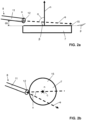
- figure 1 depicts a solar receiver 1 comprising a cooling device 8 that is configured to supply window-cooling liquid fluid 9 to the window 7 such, that the window-cooling liquid fluid 9 forms a liquid layer 10 on the window 7.
- Said liquid layer 10 is formed on the window 7 on an interior side 15 of the window 7 facing towards the cavity 3.
- the liquid layer 10 formed on the window 7 cools the window 7 by absorbing energy by combined convection, conduction, and radiation heat transfer from the window 7.
- the cooling device 8 comprises a conduit 11 in the form of a tube that has an orifice 12 for supplying the window-cooling liquid fluid 9 flowing within the conduit 11 to the window 7, see figures 2a and 2b .
- said orifice 12 is arranged in a wall of the conduit 11.
- the conduit 11 can be provided as a tube that extends around the window and which comprises a plurality of orifices along its length forming a circular array of orifices, for instance.
- Window-cooling liquid fluid 9 that flows along the conduit 11 is ejected from the conduit 11 through the orifice 12 and along an ejection direction e.
- the window 7 corresponds to a flat and circular window that is depicted from the top in figure 2b and from the side in figure 2a .
- the orifice 12 is arranged and configured such that it ejects the window-cooling liquid fluid 9 along an ejection direction e, and wherein an angle ⁇ being formed between the ejection direction e and a normal n to the window is about 80°, see figure 2a .
- the orifice 12 is arranged and configured to eject the window-cooling liquid fluid 9 along the ejection direction e that runs here at an angle ⁇ of 10° to a (fictitious) plane p running through a surface the interior side 15 of the window 7.
- the orifice 12 preferably has a diameter o in the range of 0.1 millimeter to 20 millimeter.
- the orifice is arranged at a distance do from the window 7 being in the range of 0 millimeter to 50 millimeter.
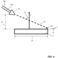
- Figure 3 depicts a solar receiver 1a comprising a cooling device 8a that comprises a conduit 11a having a nozzle 13.
- the nozzle 13 is configured to spray the window-cooling liquid fluid 9 as a cone 16 onto the window 7.
- the nozzle is arranged and configured such that an angle ⁇ between a spraying direction s along which the window-cooling liquid fluid 9 is sprayed from the nozzle 13 and a normal n to the window 7 is about +45°.
- Said normal n to the window 7 again runs normal to a (fictitious) plane p running through the surface of the interior side 15 of the window 7.
- Figure 5 depicts a solar receiver 1b comprising a cooling device 8b that comprises a conduit 11b that extends within the window 7, in particular between two layers 17a, 17b of the double-layer window 7 mentioned initially.
- the conduit 11b within the window 7 is configured to supply the window-cooling liquid fluid 9 in the window 7, whereby the window-cooling liquid fluid 9 forms the liquid layer 10 in the window 7.
- the conduit 11b within the window 7 is delimited by the two layers 17a, 17b of the window 7.
- the conduit 11b in the region of the window 7 is an integral part of the window 7.
- a distance between the layers 17a, 17b of the window define a clear width cw of the conduit 11b.
- the conduit 11b comprises regions outside of the window.
- the conduit 11b comprises an inlet region 18 via which the window-cooling liquid fluid 9 is supplied into the window 7 and an outlet region 19 via which the window-cooling liquid fluid 9 flows out of the window 7.
- Said inlet region 18 and outlet region 19 can be provided as separate components that are connected to the conduit 11b within the window 7 or these components can be a single-piece element.
- the conduit 11b extends along an extension direction E that runs parallel to the window 7 onto which the solar radiation impinges.
- the conduit 11b extending within the window 7 is in connection with the conduit 11a comprising the nozzle 13 via the outlet region 19.
- the window-cooling liquid fluid 9 is first supplied to into the window 7 via inlet region 18, then flows within the window 7 via the conduit 11b, then flows out of the window 7 and into the outlet region 19, and thereafter flows within the conduit 11a to the nozzle 13 from which it is ultimately sprayed onto the window 7.
- conduits 11, 11a, 11b of the cooling devices 8, 8a, 8b and including any other regions such as the inlet region 18 and outlet region 19 can be in connection with one or more reservoirs comprising the window-cooling liquid fluid and/or with one or more fluid circuits of an industrial system, for instance.
- the window-cooling liquid fluid 9 can at least partially provide the heat transfer fluid 4. That is, once the window-cooling liquid fluid 9 is supplied to the window 7 it can not only cool the window 7 but also become the heat transfer fluid 4 preferably after being at least partially evaporated.
- the window-cooling liquid fluid 9 and the heat transfer fluid 4 can also differ from one another, i.e. the heat transfer fluid 4 can at least partially be provided by a further fluid that does not originate from the window-cooling liquid fluid 9.
- the solar receivers 1, 1a, 1b can in each case comprise at least one further conduit 14 for supplying at least one further fluid into the cavity 3, and wherein said further fluid at least partially provides the heat transfer fluid 4.
- Said further conduit 14 is arranged between the window 7 and the absorber 6 with respect to a longitudinal direction L of the enclosure 2 and in the depicted examples protrudes from an outside of the cavity 3 partially into the cavity 3. Moreover, in the depicted examples the window 7 is arranged at a first end 21 of the enclosure 2 and outlets 20 via which the heat transfer fluid 4 exits the cavity 3 are arranged at a second end 22 of the enclosure 2 being opposite to the first end 21 of the enclosure 2.
- the longitudinal direction L of the enclosure 2 extends from the first end 21 of the enclosure 2 to the second end 22 of the enclosure 2.
- the conduit 11 comprising the orifice 12, at least in the region of the orifice 12, is arranged in the region of the first end 21 of the enclosure 2 and thus in the region of the window 7.
- the conduit 11a comprising the nozzle 13, at least in the region of the nozzle 13, is arranged in an intermediate region of the enclosure 2 being formed between the first end 21 and the second end 22 of the enclosure 2.
- the conduit 11b of the solar receiver 1b is arranged in the first end of the enclosure 21 and merges into the conduit 11a being arranged in the intermediate region of the enclosure 2. All depicted solar receivers 1, 1a, 1b comprise the absorber being arranged in a region of the second end 22 of the enclosure.
- the solar receivers 1, 1a, 1b Due to the cooling of the window 7 by the cooling devices 8, 8a, 8b the solar receivers 1, 1a, 1b according to the invention allow a heating of the window-cooling liquid fluid 9 and/or the further fluid and/or the heat transfer fluid 4 up to 1500 °C or more, such as up to 2000 °C or more within the cavity 3 by the solar radiation.
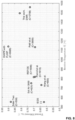
- Figure 6 shows a graph depicting state points representing isobaric heating process of water at 1 bar as realized in the solar receivers 1, 1a, 1b according to the invention and reported in the temperature-specific entropy chart of water since water was used as the window-cooling liquid fluid 9 for cooling the window 7 as well as the heat transfer fluid 4.
- the state points A to E are indicated in the solar receivers 1, 1a, 1b of figures 1 , 3 and 5 , respectively.
- the solid curve encloses the liquid-vapor coexistence region, while the dashed curve is the isobaric line at 1 bar.
- a preferred window-cooling liquid fluid 9 used to cool the window 7 and/or used as a heat transfer fluid 4 in the solar receivers 1, 1a, 1b according to the invention is water
- the spectral selectivity of liquid water was exploited.
- the absorption coefficient of liquid water is about 4 ⁇ 10 -4 cm -1 at a wavelength of around 500 nm, where the solar spectrum peaks. This means that the average penetration length for a 500 nm photon, or the reciprocal of ⁇ , is about 24 m.
- liquid water absorbs a relatively limited amount of electromagnetic radiation in the spectral range corresponding to the visible wavelength, i.e., the spectral window containing most of the solar power, letting most of the incoming radiation through.
- 10 mm of liquid water will absorb approximately 20% of the incoming solar radiation.
- water tends to be much more opaque towards radiation at longer wavelengths.
- its absorption coefficient is about 7 ⁇ 10 2 cm -1 at a wavelength of around 2000 nm, where the blackbody emission at 1200 °C peaks, i.e., approximately 6 orders of magnitude larger than in the previous case.
- the average penetration length of a 2000 nm photon is about 0.01 mm, and 10 mm of liquid water will absorb approximately 98% of the thermal radiation emitted by a 1200 °C blackbody.
- the presence of bubbles tends to reduce the absorption of radiation compared to a single-phase water layer.
- the evaporation may occur without the formation of bubbles [12].
- the radiation emerging from the window-cooling liquid fluid will then travel through a layer formed by the evolving steam, where another relatively small fraction is absorbed, being steam an absorbing gas. This absorption causes the steam to heat up, i.e., commences the steam superheating (process C to D).
- the solar receivers 1, 1a, 1b according to the invention can be seen as multi-phase solar receivers.
- the absorber 6 being a porous structure with high absorptance (90% or higher) such as, e.g., a reticulated porous ceramic (RPC) made of silicon carbide (SiC)
- RPC reticulated porous ceramic
- SiC silicon carbide
- the absorption of radiation causes heating up of the RPC to the target temperatures exceeding 1000 °C.
- a significative amount of energy is reradiated by the RPC when it reaches these temperatures (dotted arrows in figures 1 , 3 and 5 ). This reradiation is almost completely absorbed by the layer 10 of liquid water, in virtue of its relatively high absorption coefficient at these wavelengths.
- This makes the present invention a spectrally-selective solar receiver 1, 1a, 1b.
- the mass flow rate of the liquid water 9 is adjusted to match the input power in order to control the liquid level inside the solar receiver 1, 1a, 1b.
- the fact that most of the energy reradiated by the absorber is "captured" by the liquid water causes a drastic reduction of the main loss mechanism affecting high-T solar receivers, i.e., reradiation losses. This allows to maintain the demonstrated high thermal efficiencies also at the high temperatures of interest here.
- a mass flow rate of about 0.3 g / s of window-cooling liquid fluid 9 in the form of liquid water at about 20°C was fed and the radiative input power Q solar (provided by the ETH high flux solar simulator) was equal to 2950 W, corresponding to a concentration ratio of about 1850 suns.
- the same data are plotted in figure 8 , showing the receiver efficiency ⁇ th Vs the temperature of the delivered fluid T HTM out .
- the first two lines present the reference systems previously referred to as state of the art. The temperature range is below 600°C. Systems with similar performance are currently being deployed in commercial plants worldwide.
- the Solar Two plant brought the direct molten salt technology to market readiness [17] and is representative of the performance of current commercial concentrated solar power (CSP) plants of this type [6].
- CSP concentrated solar power
- the largest solar steam receiver was designed for the Ivanpah Solar Electric Generating System (ISEGS) plant[18]. The efficiency of this receiver was estimated to be around 62% [19].
- the Directly-Irradiated Annular Pressurized Receiver was developed during the 90's at the Weizmann institute, in Israel.
- the working fluid is air and the input power during the documented experiments ranged between 30 and 50 kW.
- An efficiency around 90% at 1150°C was reported, which decreased to about 70 % at 1200°C[20].
- the key feature of the DIAPR is a frustum-like fused silica window (FLHIP)[21]. Due to its rather complex shape, it is assumed that this component poses serious challenges when it comes to upscaling the receiver. No further developments have been reported for this concept after 2001.
- the present invention has the potential of bringing the GHG emissions of cement processing to zero, see figure 6 .
- solar energy as the sole energy input avoids the use of fossil fuels, thus avoiding the "energy emissions”.
- steam as the heat carrier, the exhaust leaving the kiln are basically a mixture of steam and CO 2 only. By lowering the exhaust temperature, the steam can be easily condensed and separated. This allows to obtain a stream of pure CO 2 which can be thus easily sequestrated.
- figure 9 depicts a possible integration of the present invention into the process of cement production to avoid CO 2 emissions altogether with in-situ sequestration.
- the present invention is integrated such that it provides the energy input needed by the reactions occurring in the rotary kiln, i.e., the current state of the art technology for cement production at large scale. This energy is currently provided mainly through the combustion of fossil fuels. This combustion and the associated emissions are therefore avoided in the proposed scheme.
- the CO 2 emission deriving from the reactions most notably calcination of limestone into lime, can also be effectively avoided by separating the CO 2 in the outflow stream by condensation of the accompanying steam.
Landscapes
- Engineering & Computer Science (AREA)
- Physics & Mathematics (AREA)
- Life Sciences & Earth Sciences (AREA)
- Sustainable Development (AREA)
- Sustainable Energy (AREA)
- Thermal Sciences (AREA)
- Chemical & Material Sciences (AREA)
- Combustion & Propulsion (AREA)
- Mechanical Engineering (AREA)
- General Engineering & Computer Science (AREA)
Priority Applications (2)
| Application Number | Priority Date | Filing Date | Title |
|---|---|---|---|
| EP22198281.2A EP4345399A1 (fr) | 2022-09-28 | 2022-09-28 | Récepteur solaire pour applications à haute température |
| PCT/EP2023/076907 WO2024068847A1 (fr) | 2022-09-28 | 2023-09-28 | Récepteur solaire pour applications à haute température |
Applications Claiming Priority (1)
| Application Number | Priority Date | Filing Date | Title |
|---|---|---|---|
| EP22198281.2A EP4345399A1 (fr) | 2022-09-28 | 2022-09-28 | Récepteur solaire pour applications à haute température |
Publications (1)
| Publication Number | Publication Date |
|---|---|
| EP4345399A1 true EP4345399A1 (fr) | 2024-04-03 |
Family
ID=83505636
Family Applications (1)
| Application Number | Title | Priority Date | Filing Date |
|---|---|---|---|
| EP22198281.2A Pending EP4345399A1 (fr) | 2022-09-28 | 2022-09-28 | Récepteur solaire pour applications à haute température |
Country Status (2)
| Country | Link |
|---|---|
| EP (1) | EP4345399A1 (fr) |
| WO (1) | WO2024068847A1 (fr) |
Citations (14)
| Publication number | Priority date | Publication date | Assignee | Title |
|---|---|---|---|---|
| US4164123A (en) * | 1976-08-25 | 1979-08-14 | Smith Otto J M | Solar thermal electric power plant |
| US4472367A (en) * | 1978-11-17 | 1984-09-18 | Geruldine Gibson | Method for the carbothermic reduction of metal oxides using solar energy |
| US5421322A (en) * | 1992-01-23 | 1995-06-06 | Yeda Research And Development Company Limited | Central solar receiver |
| DE10020322A1 (de) * | 2000-04-26 | 2001-11-15 | Deutsch Zentr Luft & Raumfahrt | Strahlungsemfänger |
| US6415783B1 (en) * | 1998-09-09 | 2002-07-09 | John Harrison | Solar energy receiver assembly |
| US20060174866A1 (en) * | 2005-02-10 | 2006-08-10 | Yaoming Zhang | Volumetric solar receiver |
| US20100206298A1 (en) * | 2007-08-30 | 2010-08-19 | Yeda Research And Development Company Ltd. | Solar receivers and systems thereof |
| CN102353153A (zh) * | 2011-09-05 | 2012-02-15 | 湖南大学 | 一种用于太阳能热发电系统的体积换热吸热器 |
| WO2012083097A2 (fr) * | 2010-12-17 | 2012-06-21 | University Of Delaware | Réacteur solaire thermochimique à faisceau incident utilisé pour la dissociation à ultra haute température d'oxydes solides et la création de combustibles solaires et matériaux et procédés d'utilisation associés |
| DE102011004280A1 (de) * | 2011-02-17 | 2012-08-23 | Siemens Aktiengesellschaft | Verfahren zum Betreiben eines solarthermischen Abhitzedampferzeugers |
| CH706970A1 (de) * | 2012-09-10 | 2014-03-14 | Ulrich Bech | Receiver für konzentrierte Sonnenstrahlung. |
| US20140326235A1 (en) * | 2011-12-18 | 2014-11-06 | Hanna H. Klein | Volumetric solar receiver |
| CH713765A1 (de) | 2017-05-10 | 2018-11-15 | Synhelion Sa C/O Avv Luca Tenchio | Verfahren zum Betrieb eines Receivers und Receiver zur Ausführung des Verfahrens. |
| WO2021127791A1 (fr) * | 2019-12-26 | 2021-07-01 | Synhelion Sa | Récepteur |
-
2022
- 2022-09-28 EP EP22198281.2A patent/EP4345399A1/fr active Pending
-
2023
- 2023-09-28 WO PCT/EP2023/076907 patent/WO2024068847A1/fr unknown
Patent Citations (15)
| Publication number | Priority date | Publication date | Assignee | Title |
|---|---|---|---|---|
| US4164123A (en) * | 1976-08-25 | 1979-08-14 | Smith Otto J M | Solar thermal electric power plant |
| US4472367A (en) * | 1978-11-17 | 1984-09-18 | Geruldine Gibson | Method for the carbothermic reduction of metal oxides using solar energy |
| US5421322A (en) * | 1992-01-23 | 1995-06-06 | Yeda Research And Development Company Limited | Central solar receiver |
| US6415783B1 (en) * | 1998-09-09 | 2002-07-09 | John Harrison | Solar energy receiver assembly |
| DE10020322A1 (de) * | 2000-04-26 | 2001-11-15 | Deutsch Zentr Luft & Raumfahrt | Strahlungsemfänger |
| US20060174866A1 (en) * | 2005-02-10 | 2006-08-10 | Yaoming Zhang | Volumetric solar receiver |
| US20100206298A1 (en) * | 2007-08-30 | 2010-08-19 | Yeda Research And Development Company Ltd. | Solar receivers and systems thereof |
| WO2012083097A2 (fr) * | 2010-12-17 | 2012-06-21 | University Of Delaware | Réacteur solaire thermochimique à faisceau incident utilisé pour la dissociation à ultra haute température d'oxydes solides et la création de combustibles solaires et matériaux et procédés d'utilisation associés |
| DE102011004280A1 (de) * | 2011-02-17 | 2012-08-23 | Siemens Aktiengesellschaft | Verfahren zum Betreiben eines solarthermischen Abhitzedampferzeugers |
| CN102353153A (zh) * | 2011-09-05 | 2012-02-15 | 湖南大学 | 一种用于太阳能热发电系统的体积换热吸热器 |
| US20140326235A1 (en) * | 2011-12-18 | 2014-11-06 | Hanna H. Klein | Volumetric solar receiver |
| CH706970A1 (de) * | 2012-09-10 | 2014-03-14 | Ulrich Bech | Receiver für konzentrierte Sonnenstrahlung. |
| CH713765A1 (de) | 2017-05-10 | 2018-11-15 | Synhelion Sa C/O Avv Luca Tenchio | Verfahren zum Betrieb eines Receivers und Receiver zur Ausführung des Verfahrens. |
| US20220090825A1 (en) * | 2017-05-10 | 2022-03-24 | Synhelion Sa | Method for operating a receiver and receiver for carrying out the method |
| WO2021127791A1 (fr) * | 2019-12-26 | 2021-07-01 | Synhelion Sa | Récepteur |
Non-Patent Citations (29)
| Title |
|---|
| A. HENRYR. PRASHERA. MAJUMDAR: "Five thermal energy grand challenges for decarbonization", NATURE ENERGY, vol. 5, 2020, pages 635 - 637 |
| A. KRIBUSP. DORONR. RUBINR. REUVENE. TARAGANS. DUCHANJ. KAMI: "Performance of the Directly-Irradiated Annular Pressurized Receiver ({DIAPR}) Operating at 20 Bar and 1,200 ° C", JOURNAL OF SOLAR ENERGY ENGINEERING, vol. 123, November 2001 (2001-11-01), pages 10 - 17 |
| A. R. PLOTKIN: "Solar receiver steam generator design for the Ivanpah solar electric generating system", PROCEEDINGS OF THE ASME 2011 POWER CONFERENCE, DENVER, CO, 2011 |
| C. A. KLEIN: "High-energy laser windows: Case of fused silica", OPTICAL ENGINEERING, vol. 49, 2010 |
| C. A. KLEIN: "Thermal shock resistance of infrared transmitting windows and domes", OPTICAL ENGINEERING, vol. 37, 1998, pages 2826 - 2836, XP000788491, DOI: 10.1117/1.601820 |
| C. K. HOB. D. IVERSON: "Review of high-temperature central receiver designs for concentrating solar power", RENEWABLE AND SUSTAINABLE ENERGY REVIEWS, vol. 29, 2014, pages 835 - 846 |
| F. M. TELLEZM. ROMEROP. HELLERA. VALVERDEJ. F. RECHES. ULMERG. DIBOWSKI: "Thermal performance of ''SolAir 3000 kWh'' ceramic volumetric solar receiver", PROCEEDINGS OF THE 11TH SOLARPACES INTERNATIONAL SYMPOSIUM ON CONCENTRATED SOLAR POWER AND CHEMICAL ENERGYTECHNOLOGIES, 2002 |
| G. AMBROSETTIP. GOOD: "A novel approach to high temperature solar receivers with an absorbing gas as heat transfer fluid and reduced radiative losses", SOLAR ENERGY, 2019, pages 521 - 531 |
| G. LIANGI. MUDAWAR: "Review of spray cooling - Part 2: High temperature boiling regimes and quenching applications", INTERNATIONAL JOURNAL OF HEAT AND MASS TRANSFER, vol. 115, 2017, pages 1206 - 1222 |
| G. P. THIELA. K. STARK: "To decarbonize industry, we must decarbonize heat", JOULE, vol. 5, 2021, pages 531 - 550 |
| IEA, CEMENT, March 2022 (2022-03-01), Retrieved from the Internet <URL:https://www.iea.org/reports/cement> |
| IEA, HEATING, March 2022 (2022-03-01), Retrieved from the Internet <URL:https://www.iea.org/reports/heating> |
| J. E. E. A. PACHECO, FINAL TEST AND EVALUATION RESULTS FROM THE SOLAR TWO PROJECT, 2002 |
| J. HERTELR. UHLIGM. SOHNC. SCHENKG. HELSCHH. BORNHOFT, FUSED SILICA WINDOWS FOR SOLAR RECEIVER APPLICATIONS, 2016 |
| J. KAMIA. KRIBUSB. OSTRAICHE. KOCHAVI: "A high-pressure window for volumetric solar receivers", JOURNAL OF SOLAR ENERGY ENGINEERING, TRANSACTIONS OF THE ASME, vol. 120, 1998, pages 101 - 107 |
| J. SANZ-BERMEJOJ. GONZALEZ-AGUILARM. ROMERO, PERFORMANCE ANALYSIS OF DIRECT STEAM GENERATION-CENTRAL RECEIVER SYSTEMS, 2012 |
| M. ROMEROA. STEINFELD: "Concentrating solar thermal power and thermochemical fuels", ENERGY AND ENVIRONMENTAL SCIENCE, vol. 5, 2012, pages 9234 - 9245 |
| M. SEDIGHIR. V. PADILLAR. A. TAYLORM. LAKEI. IZADGOSHASBA. ROSE: "High-temperature, point-focus, pressurised gas-phase solar receivers: A comprehensive review", ENERGY CONVERSION AND MANAGEMENT, vol. 185, 2019, pages 678 - 717, XP085632291, DOI: 10.1016/j.enconman.2019.02.020 |
| P. FRIEDLINGSTEIN: "Global Carbon Budget 2020", EARTH SYSTEM SCIENCE DATA, vol. 12, 2020, pages 3269 - 3340 |
| P. POZIVILN. ETTLINF. STUCKERA. STEINFELD: "Modular Design and Experimental Testing of a 50 kW_(th) Pressurized-Air Solar Receiver for Gas Turbines", JOURNAL OF SOLAR ENERGY ENGINEERING, vol. 137, 2015, pages 031002 - 031002 |
| P. WANGJ. B. LIF. W. BAID. Y. LIUC. XUL. ZHAOZ. F. WANG: "Experimental and theoretical evaluation on the thermal performance of a windowed volumetric solar receiver", ENERGY, vol. 119, 2017, pages 652 - 661, XP029899956, DOI: 10.1016/j.energy.2016.11.024 |
| R. BUCK, OPTICAL PERFORMANCE OF SEGMENTED APERTURE WINDOWS FOR SOLAR TOWER RECEIVERS, 2017 |
| R. BUCKT. BRAUNINGT. DENKM. PFANDERP. SCHWARZBOZLF. TELLEZ: "Solar-hybrid gas turbine-based power tower systems (REFOS", JOURNAL OF SOLAR ENERGY ENGINEERING, TRANSACTIONS OF THE ASME, vol. 124, 2002, pages 2 - 9 |
| R. SCHAPPID. RUTZF. DAHLERA. MUROYAMAP. HAUETERJ. LILLIESTAMA. PATTP. FURLERA. STEINFELD: "Drop-in fuels from sunlight and air", NATURE, vol. 601, 2022, pages 63 - 68, XP037656901, DOI: 10.1038/s41586-021-04174-y |
| SYNHELION, PRESS RELEASE, 2020, Retrieved from the Internet <URL:https://www.solarpaces.org/at-synhelion-solar-jet-fuels-get-ready-for-take-off> |
| T. NAEGLERS. SIMONM. KLEINH. C. GILS: "Quantification of the European industrial heat demand by branch and temperature level", INTERNATIONAL JOURNAL OF ENERGY RESEARCH, vol. 39, 2015, pages 2019 - 2030 |
| V. R. PATILF. KIENERA. GRYLKAA. STEINFELD: "Experimental of a solar air cavity-receiver with reticulated porous ceramic absorbers for thermal processing at above 1000 °C", SOLAR ENERGY, vol. 214, 2021, pages 72 - 85, XP086448241, DOI: 10.1016/j.solener.2020.11.045 |
| W. E. C. PRITZKOW: "Pressure loaded volumetric ceramic receiver", SOLAR ENERGY MATERIALS, vol. 24, 1991, pages 498 - 507, XP000257328, DOI: 10.1016/0165-1633(91)90086-Z |
| Z'GRAGGEN A ET AL: "Hydrogen production by steam-gasification of petroleum coke using concentrated solar power-II Reactor design, testing, and modeling", INTERNATIONAL JOURNAL OF HYDROGEN ENERGY, ELSEVIER, AMSTERDAM, NL, vol. 31, no. 6, 1 May 2006 (2006-05-01), pages 797 - 811, XP024900039, ISSN: 0360-3199, [retrieved on 20060501], DOI: 10.1016/J.IJHYDENE.2005.06.011 * |
Also Published As
| Publication number | Publication date |
|---|---|
| WO2024068847A1 (fr) | 2024-04-04 |
Similar Documents
| Publication | Publication Date | Title |
|---|---|---|
| Hadelu et al. | Exergoeconomic, carbon, and water footprint analyses and optimization of a new solar-driven multigeneration system based on supercritical CO2 cycle and solid oxide steam electrolyzer using various phase change materials | |
| Dunn et al. | A review of ammonia-based thermochemical energy storage for concentrating solar power | |
| Romero et al. | Concentrating solar thermal power and thermochemical fuels | |
| JP6440267B2 (ja) | 集光太陽光の受熱装置、反応装置及び加熱装置 | |
| Carden | Energy corradiation using the reversible ammonia reaction | |
| Sajid et al. | Thermodynamic assessment of chemical looping combustion and solar thermal methane cracking-based integrated system for green ammonia production | |
| Diver et al. | Solar test of an integrated sodium reflux heat pipe receiver/reactor for thermochemical energy transport | |
| TW202035931A (zh) | 熱利用系統及發熱裝置 | |
| Lior | Advanced energy conversion to power | |
| Flamant et al. | High temperature solar gas heating comparison between packed and fluidized bed receivers—I | |
| Hering et al. | Application of liquid metals for solar energy systems | |
| Falter et al. | Energy analysis of solar thermochemical fuel production pathway with a focus on waste heat recuperation and vacuum generation | |
| Real et al. | Renewable hydrogen production by solar-powered methanol reforming | |
| Rabade et al. | The case for solar thermal steam propulsion system for interplanetary travel: Enabling simplified ISRU utilizing NEOs and small bodies | |
| Riffat et al. | A novel heat pipe/ejector cooler | |
| CA3004353A1 (fr) | Systeme de depressurisation et de refroidissement destine a une enceinte de confinement d'une centrale nucleaire | |
| Zhu et al. | Performance investigation of a hybrid photovoltaics and mid-temperature methanol thermochemistry system | |
| Zhu et al. | A novel spectrum allocation method in the photovoltaic-thermochemical hybrid solar system | |
| EP4345399A1 (fr) | Récepteur solaire pour applications à haute température | |
| Wang et al. | Thermal and chemical reaction performance analyses of solar thermochemical volumetric receiver/reactor with nanofluid | |
| US6290185B1 (en) | Solar thermal rocket | |
| Furler | Solar thermochemical CO₂ and H₂O splitting via ceria redox reactions | |
| US11117810B2 (en) | Method for the generation of power | |
| US10266739B2 (en) | Compositions, devices, systems and methods for concentrating solar power | |
| EP2911976B1 (fr) | Système de génération d'énergie d'hydrogène à partir d'eau |
Legal Events
| Date | Code | Title | Description |
|---|---|---|---|
| PUAI | Public reference made under article 153(3) epc to a published international application that has entered the european phase |
Free format text: ORIGINAL CODE: 0009012 |
|
| STAA | Information on the status of an ep patent application or granted ep patent |
Free format text: STATUS: THE APPLICATION HAS BEEN PUBLISHED |
|
| AK | Designated contracting states |
Kind code of ref document: A1 Designated state(s): AL AT BE BG CH CY CZ DE DK EE ES FI FR GB GR HR HU IE IS IT LI LT LU LV MC MK MT NL NO PL PT RO RS SE SI SK SM TR |