EP4345274A1 - Zentrifugal gepumptes brennstoffsystem - Google Patents
Zentrifugal gepumptes brennstoffsystem Download PDFInfo
- Publication number
- EP4345274A1 EP4345274A1 EP23200623.9A EP23200623A EP4345274A1 EP 4345274 A1 EP4345274 A1 EP 4345274A1 EP 23200623 A EP23200623 A EP 23200623A EP 4345274 A1 EP4345274 A1 EP 4345274A1
- Authority
- EP
- European Patent Office
- Prior art keywords
- fuel
- phase change
- central shaft
- change chamber
- turbine
- Prior art date
- Legal status (The legal status is an assumption and is not a legal conclusion. Google has not performed a legal analysis and makes no representation as to the accuracy of the status listed.)
- Pending
Links
- 239000000446 fuel Substances 0.000 title claims abstract description 247
- 239000007789 gas Substances 0.000 claims description 49
- 239000000567 combustion gas Substances 0.000 claims description 25
- 238000002485 combustion reaction Methods 0.000 claims description 22
- 230000014759 maintenance of location Effects 0.000 claims description 13
- 238000000034 method Methods 0.000 claims description 13
- 239000002918 waste heat Substances 0.000 description 4
- 238000010438 heat treatment Methods 0.000 description 3
- 238000002716 delivery method Methods 0.000 description 2
- 238000010586 diagram Methods 0.000 description 2
- 239000007788 liquid Substances 0.000 description 2
- 230000007246 mechanism Effects 0.000 description 2
- 238000009987 spinning Methods 0.000 description 2
- 239000007858 starting material Substances 0.000 description 2
- 235000014676 Phragmites communis Nutrition 0.000 description 1
- 239000002826 coolant Substances 0.000 description 1
- 238000000605 extraction Methods 0.000 description 1
- 230000005484 gravity Effects 0.000 description 1
- 239000000463 material Substances 0.000 description 1
- 238000012986 modification Methods 0.000 description 1
- 230000004048 modification Effects 0.000 description 1
- 238000005381 potential energy Methods 0.000 description 1
Images


Classifications
-
- F—MECHANICAL ENGINEERING; LIGHTING; HEATING; WEAPONS; BLASTING
- F02—COMBUSTION ENGINES; HOT-GAS OR COMBUSTION-PRODUCT ENGINE PLANTS
- F02C—GAS-TURBINE PLANTS; AIR INTAKES FOR JET-PROPULSION PLANTS; CONTROLLING FUEL SUPPLY IN AIR-BREATHING JET-PROPULSION PLANTS
- F02C7/00—Features, components parts, details or accessories, not provided for in, or of interest apart form groups F02C1/00 - F02C6/00; Air intakes for jet-propulsion plants
- F02C7/22—Fuel supply systems
- F02C7/222—Fuel flow conduits, e.g. manifolds
-
- F—MECHANICAL ENGINEERING; LIGHTING; HEATING; WEAPONS; BLASTING
- F02—COMBUSTION ENGINES; HOT-GAS OR COMBUSTION-PRODUCT ENGINE PLANTS
- F02C—GAS-TURBINE PLANTS; AIR INTAKES FOR JET-PROPULSION PLANTS; CONTROLLING FUEL SUPPLY IN AIR-BREATHING JET-PROPULSION PLANTS
- F02C3/00—Gas-turbine plants characterised by the use of combustion products as the working fluid
- F02C3/14—Gas-turbine plants characterised by the use of combustion products as the working fluid characterised by the arrangement of the combustion chamber in the plant
- F02C3/16—Gas-turbine plants characterised by the use of combustion products as the working fluid characterised by the arrangement of the combustion chamber in the plant the combustion chambers being formed at least partly in the turbine rotor or in an other rotating part of the plant
-
- F—MECHANICAL ENGINEERING; LIGHTING; HEATING; WEAPONS; BLASTING
- F02—COMBUSTION ENGINES; HOT-GAS OR COMBUSTION-PRODUCT ENGINE PLANTS
- F02C—GAS-TURBINE PLANTS; AIR INTAKES FOR JET-PROPULSION PLANTS; CONTROLLING FUEL SUPPLY IN AIR-BREATHING JET-PROPULSION PLANTS
- F02C7/00—Features, components parts, details or accessories, not provided for in, or of interest apart form groups F02C1/00 - F02C6/00; Air intakes for jet-propulsion plants
- F02C7/12—Cooling of plants
- F02C7/16—Cooling of plants characterised by cooling medium
-
- F—MECHANICAL ENGINEERING; LIGHTING; HEATING; WEAPONS; BLASTING
- F02—COMBUSTION ENGINES; HOT-GAS OR COMBUSTION-PRODUCT ENGINE PLANTS
- F02C—GAS-TURBINE PLANTS; AIR INTAKES FOR JET-PROPULSION PLANTS; CONTROLLING FUEL SUPPLY IN AIR-BREATHING JET-PROPULSION PLANTS
- F02C7/00—Features, components parts, details or accessories, not provided for in, or of interest apart form groups F02C1/00 - F02C6/00; Air intakes for jet-propulsion plants
- F02C7/22—Fuel supply systems
-
- F—MECHANICAL ENGINEERING; LIGHTING; HEATING; WEAPONS; BLASTING
- F02—COMBUSTION ENGINES; HOT-GAS OR COMBUSTION-PRODUCT ENGINE PLANTS
- F02C—GAS-TURBINE PLANTS; AIR INTAKES FOR JET-PROPULSION PLANTS; CONTROLLING FUEL SUPPLY IN AIR-BREATHING JET-PROPULSION PLANTS
- F02C7/00—Features, components parts, details or accessories, not provided for in, or of interest apart form groups F02C1/00 - F02C6/00; Air intakes for jet-propulsion plants
- F02C7/22—Fuel supply systems
- F02C7/224—Heating fuel before feeding to the burner
-
- F—MECHANICAL ENGINEERING; LIGHTING; HEATING; WEAPONS; BLASTING
- F05—INDEXING SCHEMES RELATING TO ENGINES OR PUMPS IN VARIOUS SUBCLASSES OF CLASSES F01-F04
- F05D—INDEXING SCHEME FOR ASPECTS RELATING TO NON-POSITIVE-DISPLACEMENT MACHINES OR ENGINES, GAS-TURBINES OR JET-PROPULSION PLANTS
- F05D2260/00—Function
- F05D2260/20—Heat transfer, e.g. cooling
- F05D2260/207—Heat transfer, e.g. cooling using a phase changing mass, e.g. heat absorbing by melting or boiling
-
- F—MECHANICAL ENGINEERING; LIGHTING; HEATING; WEAPONS; BLASTING
- F05—INDEXING SCHEMES RELATING TO ENGINES OR PUMPS IN VARIOUS SUBCLASSES OF CLASSES F01-F04
- F05D—INDEXING SCHEME FOR ASPECTS RELATING TO NON-POSITIVE-DISPLACEMENT MACHINES OR ENGINES, GAS-TURBINES OR JET-PROPULSION PLANTS
- F05D2260/00—Function
- F05D2260/20—Heat transfer, e.g. cooling
- F05D2260/213—Heat transfer, e.g. cooling by the provision of a heat exchanger within the cooling circuit
Definitions
- the present disclosure relates to fuel delivery mechanisms for gas turbine engines.
- Gas turbine engines combust fuel to produce gaseous products and heat.
- the gaseous products and heat is harnessed to propel an aircraft.
- the fuel is combusted in a combustor within the gas turbine engine to produce the gaseous products and heat.
- the fuel is delivered to the combustor via a series of high-pressure pumps and injectors.
- the high-pressure pumps and injectors can be heavy and expensive.
- the fuel delivered to the combustor can be significantly below the volatilization temperature, reducing the potential energy extraction of the fuel in the Brayton Cycle of the gas turbine engine. Therefore, a fuel delivery mechanism which reduces the weight and expense of fuel pumps and increases a temperature of the fuel prior to combustion is desired.
- a fuel delivery system in one aspect of the present invention, includes a central shaft extending along a central axis.
- the central shaft includes a fuel line extending into the central shaft along the central axis.
- the fuel delivery system further includes a phase change chamber radially outward from the central shaft and fluidically connected to the fuel line.
- the fuel delivery system further includes a plurality of holes extending through a radially outer wall of the phase change chamber.
- a method of delivering fuel to a combustor of a gas turbine engine includes injecting fuel into a fuel line via a fuel pump, where the fuel line extends in a rotating central shaft and is coaxial with a central axis of the rotating central shaft. The method further includes flowing the fuel from the fuel line to a backflow preventer and forcing the fuel through the backflow preventer to flow in a radially outward direction. The method further includes flowing the fuel from the backflow preventer into a phase change chamber radially outward from the rotating central shaft, where the phase change chamber is physically connected to the rotating central shaft and rotates with the rotating central shaft.
- the method further includes transferring heat from a combustor to the phase change chamber, where the heat converts the fuel to a gaseous fuel.
- the gaseous fuel then flows from the phase change chamber to the combustor via a plurality of holes in the phase change chamber.
- the gaseous fuel is then combusted in the combustor to produce heat and combustion gases.
- a gas turbine engine in another aspect of the present invention, includes a central shaft coaxial with a central axis, the central shaft includes a fuel line extending axially within the central shaft.
- the gas turbine further includes a bearing assembly radially surrounding and rotatably connected to the central shaft, a compressor connected to the central shaft, and a compressor shroud connected to the bearing assembly and radially outward of the compressor.
- the gas turbine engine further includes a turbine connected to the central shaft, a turbine shroud radially outward of the turbine, and a phase change chamber axially between the compressor and the turbine.
- the phase change chamber is rotationally connected to the central shaft.
- the gas turbine engine further includes a backflow preventer radially between the central shaft and the phase change chamber and fluidically connecting the fuel line to the phase change chamber.
- a combustion chamber is radially outward of the phase change chamber.
- This disclosure relates to a gas turbine engine including a fuel line through a central shaft and a phase change chamber.
- the fuel line and phase change chamber permits fuel to flow radially outward during rotation of the central shaft, utilizing a centrifugal force of a rotation of the gas turbine engine to move and pressurize the fuel.
- the phase change chamber enables transfer of heat from a rotor and/or a combustor of the gas turbine engine to the fuel.
- the waste heat can volatilize the fuel in the phase change chamber, increasing a fuel efficiency of the gas turbine engine.
- the phase change chamber directs the volatilized fuel into the combustor for combustion.
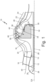
- FIG. 1 is a half cross-sectional schematic view of an embodiment of gas turbine 10 with phase change chamber 32.
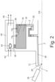
- FIG. 2 is a half cross-sectional schematic view of another embodiment of phase change chamber 32.
- gas turbine 10 includes central shaft 12, bearing 14, support structure 16, compressor rotor 18, compressor shroud 20, turbine rotor 22, turbine shroud 24, fuel nozzle 26, fuel line 28, backflow preventer 30, phase change chamber 32, fuel retention weir 34, catchment basin 36, holes 38, combustor 40, inlet air 42, combustion region 44, combustion gas 46, and central axis CA.
- Gas turbine 10 is a gas turbine engine which compresses inlet air 42, adds fuel F to compressed inlet air 42 in combustor 40, and ignites the fuel F and compressed inlet air 42 to produce heat and combustion gas 46.
- Combustion gas 46 is directed across turbine rotor 22 and is significantly expanded to turn turbine rotor 22.
- Gas turbine 10 can be attached to an aircraft to propel the aircraft.
- Central shaft 12 extends along central axis CA of gas turbine 10.
- central shaft 12 is connected to both compressor rotor 18 and turbine rotor 22 such that rotation of turbine rotor 22 rotates central shaft 12 and compressor rotor 18.
- a starter motor can rotate central shaft 12.
- the starter motor rotates central shaft 12 to a sufficient rotation speed such that compressor rotor 18 can achieve a sufficient pressure to permit combustion to begin in combustor 40.
- Bearing 14 can be connected to central shaft 12 on a radially inner side of bearing 14 and can be connected to support structure 16 on a radially outer side of bearing 14. Bearing 14 connects central shaft 12 to support structure 16 while permitting central shaft 12 to rotate freely while support structure 16 can be fixed. Bearing 14 radially and axially constrains central shaft 12 to central axis CA. Support structure 16 can be an attachment point for gas turbine 10 to the aircraft.
- compressor rotor 18 rotates.
- Compressor rotor 18 can be positioned axially between support structure 16 and phase change chamber 32.
- Compressor rotor 18 can be connected to central shaft 12.
- Compressor rotor 18 can be radially between central shaft 12 and compressor shroud 20.
- compressor rotor 18 intakes inlet air 42 and compresses inlet air 42 to a higher temperature and pressure.
- Compressor rotor 18 can have a plurality of compressor blades extending from a hub of compressor rotor 18.
- Compressor rotor 18 can be radially surrounded by compressor shroud 20.
- Compressor shroud 20 can extend axially between support structure 16 and turbine shroud 24.
- Compressor shroud 20 can form a radially outer flow surface that directs inlet air 42 into combustor 40.
- Turbine rotor 22 receives the hot and expanding combustion gas 46 from combustor 40 after combustion of the fuel F in combustion region 44.
- Turbine rotor 22 can be axially between phase change chamber 32 and an exhaust of gas turbine 10.
- Turbine rotor 22 can be connected to central shaft 12.
- Turbine rotor 22 can be radially between central shaft 12 and turbine shroud 24.
- Turbine rotor 22 is rotated by kinetic energy from the combustion gas 46 via a plurality of turbine rotor blades.
- Turbine shroud 24 extends around turbine rotor 22 and forms a radially outer gas path surface that guides combustion gas across turbine rotor 22.
- Turbine shroud 24 can be axially between compressor shroud 20 and the exhaust of gas turbine 10.
- a fuel pump pumps fuel F from a storage tank on the aircraft to fuel nozzle 26. After reaching fuel nozzle 26, fuel F is injected by fuel nozzle 26 into inlet 29 of fuel line 28. After fuel F enters inlet 29 of fuel line 28 in central shaft 12, centrifugal forces generated by rotation of central shaft 12 causes fuel F to flow within fuel line 28.
- Fuel line 28 extends axially through central shaft 12 to backflow preventer 30. A radially outward port in central shaft 12 fluidically connects fuel line 28 to backflow preventer 30. In the embodiments shown in FIGS. 1 and 2 , fuel line 28 forms a bore extending axially through a center of central shaft 12 along central axis CA.
- fuel line 28 can be parallel with central axis CA and run through a region between a center of central shaft 12 and a radially outer surface of central shaft 12. In the embodiments shown in FIGS. 1 and 2 , there is a single fuel line in central shaft 12 that defines fuel line 28. In alternative embodiments, any number of individual fuel lines can be used. Backup fuel lines enable fuel F to continue to flow to phase change chamber 32 if any individual fuel line 28 is clogged. The fuel F is moved through fuel line 28 by centrifugal forces generated by rotating central shaft 12 which act on the fuel F. The centrifugal forces apply a radially outward force on the fuel F which can be significantly greater than the force of gravity. In the embodiment of FIGS.
- fuel line 28 can gradually taper radially outward from inlet 29 to backflow preventer 30.
- the radially outward taper provides a slope and a direction of least resistance inside fuel line 28, thereby causing the centrifugal forces acting on fuel F to direct fuel F toward the radially outward port and backflow preventer 30.
- Backflow preventer 30 prevents a backwards flow of fuel F out of phase change chamber 32. As shown in FIGS. 1 and 2 , backflow preventer 30 can be radially between central shaft 12 and phase change chamber 32. Backflow preventer 30 can axially be anywhere which enables backflow preventer 30 to be connected to fuel line 28 and phase change chamber 32. Backflow preventer 30 includes a serpentine passage that causes fuel F to completely fill at least a portion of the serpentine passage to prevent vaporized fuel from backflowing out of phase change chamber 32 during operation of gas turbine 10. Backflow preventer 30 can also prevent fuel from flowing out of phase change chamber 32 when the centrifugal forces acting on central shaft 12 and phase change chamber 32 decrease, such as during a shutdown of gas turbine 10.
- backflow preventer 30 including U-Trap 48 and check flow valve 60 are discussed with regards to FIGS. 3A and 3B .
- Those of skill in the art may contemplate alternative embodiments of check valves.
- one of skill in the art may contemplate removing the backflow preventer 30 and directly connecting fuel line 28 to phase change chamber 32.
- phase change chamber is connected to an outlet of backflow preventer 30.
- Phase change chamber 32 is a chamber where fuel F accumulates during operation of gas turbine 10 and increases in temperature to a vapor. Increasing the temperature of the fuel F prior to transfer into combustor 40 reduces the consumption of useful energy to volatize the fuel inside combustor 40. The temperature of the fuel F in phase change chamber 32 can be increased using heat from combustor 40. The heat from the combustion of the fuel F in combustor 40 can radiate into phase change chamber 32 to heat and vaporize fuel F.
- phase change chamber 32 can be a hollow annular cylinder which is axisymmetric about central axis CA. As shown in the embodiment of FIG. 1 , phase change chamber 32 can be substantially flat on each radially extending end wall and substantially cylindrically shaped on a radially inner wall that extends between the radially extending end walls. In alternative embodiments the end walls can be curved, and the radially inner wall of phase change chamber 32 can curve between the end walls. As shown in the embodiment of FIG. 1 , the radially outer wall of phase change chamber 32 can curve between the end walls, with a region nearest to compressor rotor 18 being the radially outermost portion.
- the radially outer wall of phase change chamber 32 can be substantially cylindrically shaped between the axial walls. Phase change chamber 32 is enclosed by the radially outer wall, the radially inner wall, and the two radially extending end walls.
- the radially inner wall of phase change chamber 32 can be formed from compressor rotor 18 and the radially outer wall of phase change chamber 32 can be formed from turbine rotor 22.
- phase change chamber 32 can be formed separately from compressor rotor 18 and turbine rotor 22 and placed axially between compressor rotor 18 and turbine rotor 22.
- weir 34 can be formed of a radially inward projection formed on a radially inner surface of the radially outer wall of phase change chamber 32.
- Weir 34 can be an annular flange which is axisymmetric about central axis CA.
- a cross section of weir 34 is rectangular which forms a ring around central axis CA.
- a cross-section or weir 34 can be a wedge, a semi-circle, or any other shape which can project from the radially inner surface of the radially outer wall of phase change chamber 32.
- Catchment basin 36 can be formed by weir 34 and the radially outer wall.
- Catchment basin 36 is a basin which can hold the fuel F after the fuel F enters phase change chamber 32 as a liquid and as the fuel F receives heat and volatizes.
- Catchment basin 36 can be axially near backflow preventer 30 such that fuel which flows through backflow preventer 30 will flow radially outward and land into catchment basin 36.
- the plurality of holes 38 are formed through the radially outer wall of phase change chamber 32. Holes 38 permit fuel F which has been volatized in phase change chamber 32 to flow into combustor 40. Holes 38 can be circumferentially distributed about the central axis to form a ring of holes in the radially outer wall of phase change chamber 32. Alternatively, holes 38 can be placed in groups which are circumferentially distributed on the radially outer wall about the central axis CA to form hole groups in the radially outer wall of phase change chamber 32. Holes 38 can be formed on an opposite axial end of phase change chamber 32 from backflow preventer 30. Further, holes 38 can be formed radially outward from weir 34 and catchment basin 36.
- holes 38 can be formed in the radially outermost portion of the radially outer wall of phase change chamber 32 (as shown in FIG. 1 ) such that the fuel F in the phase change chamber 32 will be guided to holes 38 when phase change chamber 32 is rotating and centrifugal forces are acting on the fuel F.
- Forming holes 38 axially nearest to compressor rotor 18 and radially outward from weir 34 and catchment basin 36 enables the fuel F to enter phase change chamber 32 through backflow preventer 30, be held in catchment basin 36 until volatilization, and travel to holes 38 as volatized fuel F which can be a region of phase change chamber 32 with the highest centrifugal force.
- Combustor 40 is positioned radially outward of phase change chamber 32.
- Combustor 40 can axially be the same length as phase change chamber 32.
- a radially inner wall of combustor 40 can be formed by the radially outer wall of phase change chamber 32.
- the fuel F can be mixed with incoming air 42 and ignited in combustion region 44 to form combustion gas 46.
- the fuel F can be ignited by an ignitor or the fuel can be ignited by an already proceeding combustion process.
- Incoming air 42 can be compressed by compressor rotor 18 prior to entering combustor 40. After combusting in combustion region 44, combustion gas 46 exits combustor 40 and expands across turbine rotor 22. As such, combustion gas 46 is at a greater volume, temperature, and pressure than inlet air 42 and turbine 22 will extract some of the kinetic energy from combustion gas 46.
- Combustion gas 46 can be used to provide jet thrust if the aircraft is a turbojet.
- combustion gas 46 can be directed through a secondary turbine to drive a propeller if the aircraft is a turboprop.
- the rotational energy of central shaft 12 can drive a fan in front of compressor rotor 18 to provide the thrust if the aircraft is a turbofan.
- Those of skill in the art may contemplate alternative methods to harness the energy derived in combustion of the fuel F.
- FIGS. 3A and 3B illustrate alternative embodiments for backflow preventer 30 and will be discussed together.
- FIG. 3A is a cross-sectional schematic view of U-Trap 48.
- FIG. 3B is a cross-sectional schematic view of check valve 60.
- U-Trap 48 is an embodiment of backflow preventer 30 which is fixed-geometry and passive.
- U-Trap 48 comprises first portion 50 which extends radially directly outward, second portion 52 which extends axially parallel to central axis CA in a first direction, third portion 54 which extends radially directly inwards, fourth portion 56 which extends axially parallel to central axis CA in the first direction, and fifth portion 58 which extends radially directly outward.
- the fuel F flows from fuel line 28 into first portion 50. Once fuel F has flowed into first portion 50, fuel F enters second portion 52 and third portion 54 and completely fills third portion 54. After filling third portion 54, fuel F will flow into fourth portion 56 and fifth portion 58 and then into phase change chamber 32.
- Check valve 60 is an embodiment of backflow preventer 30 which has a dynamicgeometry and is passive.
- Check valve 60 can comprise one or more flexible rubber diaphragms positioned in a normally closed position.
- backflow preventer 30 comprises a single axisymmetric rubber diaphragm 62 which only permits flow in a radially outward direction.
- check valves including ball check valves, swing check valves, stop-check valves, lift-check valves, in-line check valves, reed valves, or any other check valve which permits flow control.
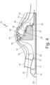
- FIG. 4 is a half cross-sectional schematic view of a second embodiment of gas turbine engine 10 with phase change chamber 32.
- gas turbine 10 includes central shaft 12, bearing 14, support structure 16, compressor rotor 18, compressor shroud 20, turbine rotor 22, turbine shroud 24, fuel pump 26, fuel line 28, backflow preventer 30, phase change chamber 32, fuel retention weir 34, catchment basin 36, holes 38, combustor 40, inlet air 42, combustion region 44, combustion gas 46, and central axis CA.
- Central shaft 12, bearing 14, support structure 16, compressor rotor 18, compressor shroud 20, turbine rotor 22, turbine shroud 24, fuel pump 26, backflow preventer 30, phase change chamber 32, fuel retention weir 34, catchment basin 36, holes 38, combustor 40, inlet air 42, combustion region 44, combustion gas 46, and central axis CA are substantially as described in FIG. 1 .
- Fuel line 28 of FIG. 4 extends axially through central shaft 12 from fuel nozzle 26 through a first end to a second end of turbine rotor 22. At the second end of turbine rotor 22, fuel line 28 extends radially outward and extends from the second end back to the first end through turbine rotor 22.
- the fuel can absorb some waste heat from turbine rotor 22.
- the fuel acts as a coolant, removing waste heat from turbine rotor 22 and heating the fuel. Heating the fuel can decrease a length of time in catchment basin 36 prior to volatilization.
- FIG. 5 is a flow diagram of a fuel delivery method for gas turbine engine 10 of FIG. 1 .
- the fuel delivery method includes first step 102 through tenth step 120.
- First step 102 comprises injecting fuel F into rotating fuel line 28.
- the fuel F can be injected into fuel line 28 through fuel nozzle 26 fluidically connected to a fuel pump.
- fuel line 28 can be in central shaft 12.
- Second step 104 comprises forcing the fuel F in a radially outward direction.
- the fuel F can be forced in a radially outward direction by spinning central shaft 12 such that centrifugal forces caused by the spinning of central shaft 12 act on the fuel F.
- Fuel line 28 can taper radially outward as fuel line 28 extends in an axial direction to accentuate the fuel flow caused by the centrifugal forces.
- Third step 106 comprises flowing the fuel F to rotating backflow preventer 30.
- the fuel F can be flowed to rotating backflow preventer 30 through fuel line 28 as described in second step 104.
- Fuel line 28 can pass through turbine rotor 22 prior to connecting to backflow preventer 30 to enable waste heat to be drawn from turbine rotor 22 into the fuel F. Passing fuel line 28 through turbine rotor 22 can increase a temperature of the fuel F prior to entering phase change chamber 32, which can decrease a time for the fuel F to volatilization in phase change chamber 32.
- Fourth step 108 comprises flowing the fuel F to rotating phase change chamber 32 through backflow preventer 30 which ensures the fuel F only flows in a radially outward direction.
- Fifth step 110 comprises heating and volatizing the fuel F in rotating phase change chamber 32.
- the fuel F Once the fuel F enters phase change chamber 32, the fuel F will be held behind weir 34 in catchment basin 36 and will begin receiving heat from turbine rotor 22 and combustor 40. Once the fuel F receives enough heat, the fuel F will volatize from a liquid to a gas.
- Sixth step 112 comprises flowing the volatized fuel F into combustor 40. Once the fuel F has been volatized, the volatized fuel F flows through holes 38 into combustor 40. Holes 38 can be formed through a radially outer wall of phase change chamber 32 in a radially outermost region.
- Seventh step 114 comprises combusting the volatized fuel F to produce heat and combustion gases. Once the volatized fuel flows through holes 38 into combustor 40, the volatized fuel F can be mixed and combusted with inlet air 42 in combustion region 44 to produce heat and combustion gases which form combustion gas 46. The volatized fuel F can be ignited by an ongoing combustion process, and/or the volatized fuel F can be ignited by an ignitor.
- Eighth step 116 comprises rotating turbine rotor 22 via the combustion gases.
- the combustion gases produced in combustion region 44 then flow from combustor 40 into turbine rotor 22.
- Turbine rotor 22 can then be rotated by combustion gas 46.
- Turbine rotor 22 can be rotated clockwise or counterclockwise depending on an orientation of the plurality of blades on turbine rotor 22.
- Ninth step 118 comprises rotating central shaft 12 via turbine rotor 22. Since turbine rotor 22 is connected to central shaft 12, as turbine rotor 22 rotates central shaft 12 will likewise rotate.
- Tenth step 120 comprises rotating fuel line 28, backflow preventer 30, and phase change chamber 32. Since fuel line 28, backflow preventer 30, and phase change chamber 32 are connected to central shaft 12, as turbine rotor 22 rotates, central shaft 12 and the components connected to central shaft 12 are likewise rotated. The rotation of central shaft 12 creates a centrifugal force on all of the components which drives the fuel F through fuel line 28, backflow preventer 30, and phase change chamber 32.
- a fuel delivery system in one embodiment, includes a central shaft extending along a central axis.
- the central shaft includes a fuel line extending into the central shaft along the central axis.
- the fuel delivery system further includes a phase change chamber radially outward from the central shaft and fluidically connected to the fuel line.
- the fuel delivery system further includes a plurality of holes extending through a radially outer wall of the phase change chamber.
- the fuel delivery system of the preceding paragraph can optionally include, additionally and/or alternatively, any one or more of the following features, configurations and/or additional components:
- a gas turbine engine in another embodiment, includes the fuel delivery system of the previous embodiment and any of the optional additional/alternative features.
- the gas turbine further includes a bearing assembly radially surrounding and rotatably connected to the central shaft, a compressor connected to the central shaft, and a compressor shroud connected to the bearing assembly and radially outward of the compressor.
- the gas turbine engine further includes a turbine connected to the central shaft, a turbine shroud radially outward of the turbine, and the phase change chamber is located axially between the compressor and the turbine.
- the phase change chamber is rotationally connected to the central shaft.
- the gas turbine engine further includes a backflow preventer radially between the central shaft and the phase change chamber and fluidically connecting the fuel line to the phase change chamber.
- a combustion chamber is radially outward of the phase change chamber.
- a method of delivering fuel to a combustor of a gas turbine engine includes injecting fuel into a fuel line via a fuel pump, where the fuel line extends in a rotating central shaft and is coaxial with a central axis of the rotating central shaft. The method further includes flowing the fuel from the fuel line to a backflow preventer and forcing the fuel through the backflow preventer to flow in a radially outward direction. The method further includes flowing the fuel from the backflow preventer into a phase change chamber radially outward from the rotating central shaft, where the phase change chamber is physically connected to the rotating central shaft and rotates with the rotating central shaft.
- the method further includes transferring heat from a combustor to the phase change chamber, where the heat converts the fuel to a gaseous fuel.
- the gaseous fuel then flows from the phase change chamber to the combustor via a plurality of holes in the phase change chamber.
- the gaseous fuel is then combusted in the combustor to produce heat and combustion gases.
- the method of the preceding paragraph can optionally include, additionally and/or alternatively, any one or more of the following features, configurations and/or additional components: directing the combustion gases to a turbine, wherein the turbine is connected to the central shaft; and rotating, via the turbine, the central shaft about the central axis.
- a gas turbine engine in another embodiment, includes a central shaft coaxial with a central axis, the central shaft includes a fuel line extending axially within the central shaft.
- the gas turbine further includes a bearing assembly radially surrounding and rotatably connected to the central shaft, a compressor connected to the central shaft, and a compressor shroud connected to the bearing assembly and radially outward of the compressor.
- the gas turbine engine further includes a turbine connected to the central shaft, a turbine shroud radially outward of the turbine, and a phase change chamber axially between the compressor and the turbine.
- the phase change chamber is rotationally connected to the central shaft.
- the gas turbine engine further includes a backflow preventer radially between the central shaft and the phase change chamber and fluidically connecting the fuel line to the phase change chamber.
- a combustion chamber is radially outward of the phase change chamber.
- the gas turbine engine of the preceding paragraph can optionally include, additionally and/or alternatively, any one or more of the following features, configurations and/or additional components:
Landscapes
- Engineering & Computer Science (AREA)
- Chemical & Material Sciences (AREA)
- Combustion & Propulsion (AREA)
- Mechanical Engineering (AREA)
- General Engineering & Computer Science (AREA)
- Structures Of Non-Positive Displacement Pumps (AREA)
Applications Claiming Priority (2)
| Application Number | Priority Date | Filing Date | Title |
|---|---|---|---|
| US202263378045P | 2022-09-30 | 2022-09-30 | |
| US18/154,683 US12065971B2 (en) | 2022-09-30 | 2023-01-13 | Centrifugally pumped fuel system |
Publications (1)
| Publication Number | Publication Date |
|---|---|
| EP4345274A1 true EP4345274A1 (de) | 2024-04-03 |
Family
ID=88236491
Family Applications (1)
| Application Number | Title | Priority Date | Filing Date |
|---|---|---|---|
| EP23200623.9A Pending EP4345274A1 (de) | 2022-09-30 | 2023-09-28 | Zentrifugal gepumptes brennstoffsystem |
Country Status (2)
| Country | Link |
|---|---|
| US (1) | US12065971B2 (de) |
| EP (1) | EP4345274A1 (de) |
Families Citing this family (1)
| Publication number | Priority date | Publication date | Assignee | Title |
|---|---|---|---|---|
| IL311619A (en) * | 2024-03-20 | 2025-10-01 | Rafael Advanced Defense Systems Ltd | Printed motor |
Citations (2)
| Publication number | Priority date | Publication date | Assignee | Title |
|---|---|---|---|---|
| US8763405B2 (en) * | 2008-04-09 | 2014-07-01 | Williams International Co., L.L.C. | Gas turbine engine rotary injection system and method |
| US20140193274A1 (en) * | 2008-04-09 | 2014-07-10 | Williams International Co., L.L.C. | Fuel-cooled bladed rotor of a gas turbine engine |
Family Cites Families (21)
| Publication number | Priority date | Publication date | Assignee | Title |
|---|---|---|---|---|
| US3932988A (en) | 1972-10-25 | 1976-01-20 | Beaufrere Albert H | Fuel slinger combustor |
| US4038815A (en) * | 1973-03-30 | 1977-08-02 | Northern Research And Engineering Corporation | Gas turbine |
| US4040251A (en) * | 1975-06-04 | 1977-08-09 | Northern Research And Engineering Corporation | Gas turbine combustion chamber arrangement |
| JP3030689B2 (ja) * | 1995-09-08 | 2000-04-10 | 本田技研工業株式会社 | ガスタービンエンジン |
| DE19852768A1 (de) * | 1998-11-16 | 2000-05-18 | Bmw Rolls Royce Gmbh | Kleingasturbine mit einer Radial- oder Slinger-Brennkammer |
| US6293338B1 (en) * | 1999-11-04 | 2001-09-25 | Williams International Co. L.L.C. | Gas turbine engine recuperator |
| US7036321B2 (en) | 2003-10-08 | 2006-05-02 | Honeywell International, Inc. | Auxiliary power unit having a rotary fuel slinger |
| US6988367B2 (en) * | 2004-04-20 | 2006-01-24 | Williams International Co. L.L.C. | Gas turbine engine cooling system and method |
| US7251942B2 (en) * | 2004-06-29 | 2007-08-07 | Honeywell International Inc. | Integrated gearless and nonlubricated auxiliary power unit |
| WO2009126847A1 (en) * | 2008-04-09 | 2009-10-15 | Williams International Co., L.L.C. | Gas turbine engine cooling system and method |
| US8640464B2 (en) * | 2009-02-23 | 2014-02-04 | Williams International Co., L.L.C. | Combustion system |
| US8479492B2 (en) * | 2011-03-25 | 2013-07-09 | Pratt & Whitney Canada Corp. | Hybrid slinger combustion system |
| JP5693514B2 (ja) * | 2012-04-06 | 2015-04-01 | 三菱重工業株式会社 | ガスタービン燃焼器 |
| US9903214B2 (en) * | 2015-05-26 | 2018-02-27 | General Electric Company | Internally cooled turbine blisk and method of manufacture |
| CA2921053C (en) * | 2016-02-16 | 2020-06-16 | Greentech Gas Turbine Inc. / Turbine A Gaz Greentech Inc. (Known By Either Name) | Gas turbine blower/pump |
| KR102566355B1 (ko) * | 2016-02-16 | 2023-08-11 | 오마르 하무드 | 가스 터빈 송풍기/펌프 |
| KR102268593B1 (ko) | 2016-07-01 | 2021-06-23 | 한화에어로스페이스 주식회사 | 슬링거 연소기 및 이를 구비한 가스 터빈 엔진 시스템 |
| DE112020005348T5 (de) * | 2019-10-30 | 2022-08-11 | Ihi Corporation | Kühlstruktur und Turbolader |
| US11952946B2 (en) * | 2021-10-15 | 2024-04-09 | Rtx Corporation | Turbine engine with preheat of cryogenic fuel via intermediate fluid |
| ES3040736T3 (en) * | 2021-11-29 | 2025-11-04 | Airbus Operations Slu | Gas turbine |
| CN216910623U (zh) * | 2022-02-23 | 2022-07-08 | 浙江康松动力科技有限公司 | 一种燃油泵甩油机 |
-
2023
- 2023-01-13 US US18/154,683 patent/US12065971B2/en active Active
- 2023-09-28 EP EP23200623.9A patent/EP4345274A1/de active Pending
Patent Citations (2)
| Publication number | Priority date | Publication date | Assignee | Title |
|---|---|---|---|---|
| US8763405B2 (en) * | 2008-04-09 | 2014-07-01 | Williams International Co., L.L.C. | Gas turbine engine rotary injection system and method |
| US20140193274A1 (en) * | 2008-04-09 | 2014-07-10 | Williams International Co., L.L.C. | Fuel-cooled bladed rotor of a gas turbine engine |
Also Published As
| Publication number | Publication date |
|---|---|
| US12065971B2 (en) | 2024-08-20 |
| US20240110519A1 (en) | 2024-04-04 |
Similar Documents
| Publication | Publication Date | Title |
|---|---|---|
| CN109424440B (zh) | 燃气涡轮发动机及其一个或多个部件的冷却和加压方法 | |
| US8776525B2 (en) | Gas turbine engine and combustor | |
| CN106368822B (zh) | 用于涡轮发动机的冷却系统 | |
| US11306658B2 (en) | Cooling system for a turbine engine | |
| CN100404839C (zh) | 尾部flade发动机 | |
| JP2017040263A (ja) | 混合流ターボコア | |
| US3703081A (en) | Gas turbine engine | |
| JP2017040264A (ja) | 圧縮機ブリード補助タービン | |
| JP2017040265A (ja) | ガスタービンエンジンのための空気流噴射ノズル | |
| JP2011085141A (ja) | ガスタービンエンジン温度調節冷却流 | |
| JP2011106461A (ja) | 外側ファンを有するガスタービンエンジン | |
| JP2016211578A (ja) | 間接駆動式ターボファンエンジンのロータシャフトを支持するシステム | |
| CN107975424A (zh) | 轴向涡轮机压缩机的除冰鼻部 | |
| US12221905B1 (en) | Turbine engine including a steam system | |
| EP4345274A1 (de) | Zentrifugal gepumptes brennstoffsystem | |
| CN120026988A (zh) | 包括蒸汽系统的涡轮发动机 | |
| US12435664B2 (en) | Gas turbine engine with water recovery system | |
| WO2013102113A2 (en) | Gas turbine engine with variable speed turbines | |
| US12571345B2 (en) | Turbine engine including a steam system | |
| RU2320885C2 (ru) | Двухконтурный газотурбинный вентиляторный двигатель | |
| CN119654480A (zh) | 飞行器涡轮发动机 | |
| RU2271461C2 (ru) | Двухконтурный комбинированный газотурбинный винтовентиляторный двигатель | |
| US12416260B2 (en) | Turbine engine including a steam system | |
| US20250251129A1 (en) | Gas turbine engine having a steam generating system providing steam to a combustor | |
| US11603794B2 (en) | Method and apparatus for increasing useful energy/thrust of a gas turbine engine by one or more rotating fluid moving (agitator) pieces due to formation of a defined steam region |
Legal Events
| Date | Code | Title | Description |
|---|---|---|---|
| PUAI | Public reference made under article 153(3) epc to a published international application that has entered the european phase |
Free format text: ORIGINAL CODE: 0009012 |
|
| STAA | Information on the status of an ep patent application or granted ep patent |
Free format text: STATUS: THE APPLICATION HAS BEEN PUBLISHED |
|
| AK | Designated contracting states |
Kind code of ref document: A1 Designated state(s): AL AT BE BG CH CY CZ DE DK EE ES FI FR GB GR HR HU IE IS IT LI LT LU LV MC ME MK MT NL NO PL PT RO RS SE SI SK SM TR |
|
| STAA | Information on the status of an ep patent application or granted ep patent |
Free format text: STATUS: REQUEST FOR EXAMINATION WAS MADE |
|
| 17P | Request for examination filed |
Effective date: 20241003 |
|
| RBV | Designated contracting states (corrected) |
Designated state(s): AL AT BE BG CH CY CZ DE DK EE ES FI FR GB GR HR HU IE IS IT LI LT LU LV MC ME MK MT NL NO PL PT RO RS SE SI SK SM TR |