EP4345235B1 - Gedämpftes scharnier für türen von möbeln und dergleichen - Google Patents
Gedämpftes scharnier für türen von möbeln und dergleichen Download PDFInfo
- Publication number
- EP4345235B1 EP4345235B1 EP23189407.2A EP23189407A EP4345235B1 EP 4345235 B1 EP4345235 B1 EP 4345235B1 EP 23189407 A EP23189407 A EP 23189407A EP 4345235 B1 EP4345235 B1 EP 4345235B1
- Authority
- EP
- European Patent Office
- Prior art keywords
- hinge
- articulation
- connecting rods
- arm
- door
- Prior art date
- Legal status (The legal status is an assumption and is not a legal conclusion. Google has not performed a legal analysis and makes no representation as to the accuracy of the status listed.)
- Active
Links
Images





Classifications
-
- E—FIXED CONSTRUCTIONS
- E05—LOCKS; KEYS; WINDOW OR DOOR FITTINGS; SAFES
- E05D—HINGES OR SUSPENSION DEVICES FOR DOORS, WINDOWS OR WINGS
- E05D7/00—Hinges or pivots of special construction
- E05D7/04—Hinges adjustable relative to the wing or the frame
- E05D7/0407—Hinges adjustable relative to the wing or the frame the hinges having two or more pins and being specially adapted for cabinets or furniture
-
- E—FIXED CONSTRUCTIONS
- E05—LOCKS; KEYS; WINDOW OR DOOR FITTINGS; SAFES
- E05F—DEVICES FOR MOVING WINGS INTO OPEN OR CLOSED POSITION; CHECKS FOR WINGS; WING FITTINGS NOT OTHERWISE PROVIDED FOR, CONCERNED WITH THE FUNCTIONING OF THE WING
- E05F5/00—Braking devices, e.g. checks; Stops; Buffers
- E05F5/06—Buffers or stops limiting opening of swinging wings, e.g. floor or wall stops
- E05F5/08—Buffers or stops limiting opening of swinging wings, e.g. floor or wall stops with springs
-
- E—FIXED CONSTRUCTIONS
- E05—LOCKS; KEYS; WINDOW OR DOOR FITTINGS; SAFES
- E05D—HINGES OR SUSPENSION DEVICES FOR DOORS, WINDOWS OR WINGS
- E05D3/00—Hinges with pins
- E05D3/06—Hinges with pins with two or more pins
- E05D3/14—Hinges with pins with two or more pins with four parallel pins and two arms
- E05D3/142—Hinges with pins with two or more pins with four parallel pins and two arms with at least one of the hinge parts having a cup-shaped fixing part, e.g. for attachment to cabinets or furniture
-
- E—FIXED CONSTRUCTIONS
- E05—LOCKS; KEYS; WINDOW OR DOOR FITTINGS; SAFES
- E05F—DEVICES FOR MOVING WINGS INTO OPEN OR CLOSED POSITION; CHECKS FOR WINGS; WING FITTINGS NOT OTHERWISE PROVIDED FOR, CONCERNED WITH THE FUNCTIONING OF THE WING
- E05F1/00—Closers or openers for wings, not otherwise provided for in this subclass
- E05F1/08—Closers or openers for wings, not otherwise provided for in this subclass spring-actuated, e.g. for horizontally sliding wings
- E05F1/10—Closers or openers for wings, not otherwise provided for in this subclass spring-actuated, e.g. for horizontally sliding wings for swinging wings, e.g. counterbalance
- E05F1/12—Mechanisms in the shape of hinges or pivots, operated by springs
- E05F1/1246—Mechanisms in the shape of hinges or pivots, operated by springs with a coil spring perpendicular to the pivot axis
- E05F1/1253—Mechanisms in the shape of hinges or pivots, operated by springs with a coil spring perpendicular to the pivot axis with a compression spring
-
- E—FIXED CONSTRUCTIONS
- E05—LOCKS; KEYS; WINDOW OR DOOR FITTINGS; SAFES
- E05F—DEVICES FOR MOVING WINGS INTO OPEN OR CLOSED POSITION; CHECKS FOR WINGS; WING FITTINGS NOT OTHERWISE PROVIDED FOR, CONCERNED WITH THE FUNCTIONING OF THE WING
- E05F3/00—Closers or openers with braking devices, e.g. checks; Construction of pneumatic or liquid braking devices
- E05F3/20—Closers or openers with braking devices, e.g. checks; Construction of pneumatic or liquid braking devices in hinges
-
- E—FIXED CONSTRUCTIONS
- E05—LOCKS; KEYS; WINDOW OR DOOR FITTINGS; SAFES
- E05F—DEVICES FOR MOVING WINGS INTO OPEN OR CLOSED POSITION; CHECKS FOR WINGS; WING FITTINGS NOT OTHERWISE PROVIDED FOR, CONCERNED WITH THE FUNCTIONING OF THE WING
- E05F5/00—Braking devices, e.g. checks; Stops; Buffers
- E05F5/006—Braking devices, e.g. checks; Stops; Buffers for hinges having a cup-shaped fixing part, e.g. for attachment to cabinets or furniture
-
- E—FIXED CONSTRUCTIONS
- E05—LOCKS; KEYS; WINDOW OR DOOR FITTINGS; SAFES
- E05Y—INDEXING SCHEME ASSOCIATED WITH SUBCLASSES E05D AND E05F, RELATING TO CONSTRUCTION ELEMENTS, ELECTRIC CONTROL, POWER SUPPLY, POWER SIGNAL OR TRANSMISSION, USER INTERFACES, MOUNTING OR COUPLING, DETAILS, ACCESSORIES, AUXILIARY OPERATIONS NOT OTHERWISE PROVIDED FOR, APPLICATION THEREOF
- E05Y2900/00—Application of doors, windows, wings or fittings thereof
- E05Y2900/20—Application of doors, windows, wings or fittings thereof for furniture, e.g. cabinets
Definitions
- the present invention relates to a cushioned hinge for doors of furniture items, such as cupboards and the like, in particular for high-capacity cupboards.
- hinges for furniture items are used to allow the opening and closing of doors and comprise a fixed part or arm, to be attached internally to a side wall or shoulder of the furniture item, and a movable part, in the form of a bowl or box, to be attached to the door, said fixed and movable parts being oscillatingly connected one to the other by a system of articulated levers, generally comprising at least one pair of connecting rods or rockers.
- hinges are normally provided with elastic means suitable for stressing the door in closure and with damping devices, which intervene in the final phase of closure of the door, slowing down the stroke thereof and thus preventing it from slamming with force against the body of the furniture item.
- hinges are, for example, described in document CN 211691975 , which has the following main limitations:
- US 2018/0252016 A1 describes a hinge for furniture items comprising a flattened fixed part designed to be inserted in the thickness of the upper or lower wall of a furniture item, and a movable part that can be attached to the door, the fixed part and the movable part being connected one to the other by means of an articulation system comprising two rockers and respective axes of articulation.
- the two rockers are placed on a same plane, which is the median plane of the fixed part of the hinge, perpendicular to said axes of articulation.
- the fixed part of the hinge can only be attached to a horizontal plane of the furniture item, i.e. the upper or lower plane.
- the object of the invention is to eliminate the disadvantages of the hinges known from documents US 2018/0252016 Al and CN 211691975 , described above.
- one object of the invention is to provide a cushioned hinge for doors of high-capacity furniture items, attachable to a side wall of said furniture item by insertion in a seat formed in the thickness of said side wall, and which leaves the edge of the door completely intact, so that the box remains hidden from view when the door is closed.
- Another object of the invention is to provide such a hinge which allows for more or less coverage, with movement of the door inwards.
- Yet a further object of the invention is to provide such a hinge, the box whereof is shaped so as to facilitate the adjustments thereof.
- the cushioned hinge for doors of furniture items or the like comprises:
- the hinge according to the invention denoted as a whole by reference numeral 1, comprises a fixed part 2, which can be attached to a side wall or shoulder 4 of the furniture item, and a movable part 3 which can be attached to a door 5 of the furniture item, connected one to the other by means of an articulated system.
- the fixed part 2 comprises an arm 10, mounted, with the possibility of slight adjustments, as will be discussed here below, in a base 20 housed in a seat 6 formed in the thickness of the side wall 4, while the movable part 3 comprises a cage 30 mounted, also with slight adjustment possibilities, in a box 40, housed in a corresponding seat 7 formed on the door 5 (see in particular Figure 9 ).
- the arm 10 and the cage 30 are connected one to the other by means of the above-mentioned articulated system, substantially comprising a central connecting rod 11 and a pair of lateral connecting rods 12.
- the central connecting rod 11 is a slightly arched lever, pivoted, on one side, between two small lugs 13 projecting frontally from the arm 10 by means of a nail 14 constituting a first axis of articulation (see in particular Figure 2 ) and, on the other side, between a pair of small lugs 15 provided internally to the cage 30 by means of a knurled rod 16 constituting a second axis of articulation.
- the lateral connecting rods 12 have a particular conformation, substantially in the shape of an upside-down Y, with the central stem 54 prolonged with an arched shape that extends towards the cage 30.
- the lateral connecting rods 12 are pivoted, on one side, to the arm 10 in a third axis of articulation formed by a nail 17 which traverses approximately centrally the connecting rods 12 and is placed in a more internal position with respect to the first axis of articulation 14.
- the lateral connecting rods 12 are pivoted, at the ends of their arched extensions, in a fourth axis of articulation constituted by a nail 18, externally to a pair of small lugs 19 provided in the cage 30, in an aligned, raised and more advanced position with respect to the pair of small lugs 15.
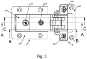
- the base 20 of the fixed part 2 of the hinge has a central part, open frontally, which is housed in the seat 6 of the side wall of the furniture item, and a plate-shaped frame 21 that extends along a plane parallel to said axes of articulation 14, 16, 17, 18 attached to this wall by means of screws not shown.
- a hollow longitudinal block 22 is provided, substantially parallelepipedal in shape, open frontally, where an upper longitudinal slot 23 is provided, while transverse reliefs 24 are provided to the rear of the upper wall of the block 22.
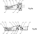
- the arm 10 is housed in the central part of the base 20 and has a first rear section 10', distal from the movable part 3, which is placed substantially flush with said plate-shaped frame 21, and a second proximal section 10", inclined upwards, such that it protrudes with respect to the plate-shaped frame 21, as can be seen more clearly in the sectional views of Figures 6a to 8b .
- the purpose of the protruding inclined section 10" of the arm 10, to which the connecting rods 11, 12 are pivoted, is to be able to form the aforesaid seat 7 for housing the movable part 3 of the hinge, entirely within the profile of the door 5, without affecting the edge of the same (see Fig. 9 ), in such a way that there are no visible parts of the hinge with the door closed.
- the arm 10 is restrained to the base 20 by means of a pin 25, which traverses longitudinal openings 26 in the side walls of the base 20 and corresponding circular holes 27 in the side walls of the arm 10, in such a way that the arm 10 can oscillate and translate longitudinally for the distance allowed by the openings 26.
- the arm 10 is likewise attached to the base 20 by means of a regulation screw 28, having a shank with a peripheral groove 29, such that it is housed in the slot 23 of the block 22 (see in particular Figures 6 ), in such a way that a rotation in one direction or the other of the screw 28, inserted in a threaded hole 31 of the arm 10, produces a raising or lowering of the arm 10 with respect to the base 20, which corresponds to a lateral adjustment of the door 5, by means of the movement imparted thereto by the system of articulation.
- a cam 32 is instead provided, having below a spiral profile that goes to engage with the transverse projections 24 provided above the block 22 (see Figures 6 ), and that can be actuated by rotation of a head 34 projecting above from a hole 33 of the arm 10.
- the base 20, and generally the entire fixed part 2 of the hinge is developed along a plane parallel to the axes of articulation 14, 16, 17, 18.
- the cage 30 is attached to the box 40 by means of screws 35, inserted in transverse slots 36 provided in lateral fins 38 of the cage 30, that are screwed into circular holes 37 provided in the box 40. In this way the position of the cage 30 can be regulated transversally with respect to the box 40, which corresponds to a vertical regulation of the door 5.
- the hinge also comprises a system of control of the movement of closure of the door, made up of elastic means suitable for bringing the door into the closing position and for keeping it in this position, and deceleration means suitable for braking the door in the final phase of closure to prevent it from slamming with force against the body of the furniture item.
- the deceleration means comprise a shock absorber or damper 50, made up of a cylinder, for example an oil cylinder, housed in the hollow block 22, the stem 51 of which traverses the rear wall 41 of the block and abuts against a plate 42 positioned behind the wall 41.
- a shock absorber or damper 50 made up of a cylinder, for example an oil cylinder, housed in the hollow block 22, the stem 51 of which traverses the rear wall 41 of the block and abuts against a plate 42 positioned behind the wall 41.
- the damper 50 is actuated by a lever 52 pivoted on an axle 53 that connects the ends of respective shanks 55 of the Y conformation of the lateral connecting rods 12.
- the elastic means comprise a pair of springs 60 placed in the base 20, at the two sides of the block 22, which also go to abut, with one end, against the aforementioned plate 42, which acts as anchorage for the same.
- the springs 60 in this case of the helical type, are placed on respective spring holders 61, having a tapered stem 62, such as to determine a stop 63, against which the other end of the corresponding spring at least partially abuts.
- each spring holder 61 has, at the free end, a sort of eyelet 64 which goes to hook up with a corresponding peg 65 protruding internally from the end of the other leg 56 of the Y conformation of the corresponding lateral connecting rod 12.
- the springs 60 that are compressed with the door open ( Figures 7b , 8b ), tend to unload and accompany the door in the phase of closure, exerting a force on the lateral connecting rods 12, that rotate around their respective axis of articulation 17.
- the central connecting rod 11 and the lateral connecting rods 12 remain almost totally contained in the box 40 of the movable part 3 of the hinge, in the closed condition, which, together with the inclined section 10" of the arm 10, allows the relative seat 7 to be formed completely inside the door 5, without affecting its edge, such that, with the door closed, it remains entirely concealed.
- the elastic means and the damper are actuated by separate means, which makes separate adjustments possible.
Landscapes
- Engineering & Computer Science (AREA)
- Mechanical Engineering (AREA)
- Hinges (AREA)
- Closing And Opening Devices For Wings, And Checks For Wings (AREA)
Claims (10)
- Gedämpftes Scharnier (1) für Türen von Möbelstücken oder dergleichen, umfassend:- ein feststehendes Teil (2), das an einer Seitenwand oder einer Schulter (4) des Möbelstücks befestigt werden kann;- ein bewegliches Teil (3), das an einer Tür (5) des Möbelstücks befestigt werden kann;- ein Gelenksystem, das die feststehenden (2) und die beweglichen (3) Teile des Scharniers miteinander verbindet, umfassend eine Vielzahl von Kolbenstangen (11, 12) und Gelenkachsen (14, 16, 17, 18);- elastische Mittel (60), die in der Schließrichtung des Scharniers wirken;- linear betätigte Verzögerungsmittel (50), die dazu dienen, den letzten Abschnitt des Verschlusshubs des Scharniers zu verlangsamen;dadurch gekennzeichnet, dass der feststehende Teil (2) eine Basis (20) mit einem zentralen, nach vorne offenen Teil, der dazu bestimmt ist, in einem Sitz (6) aufgenommen zu werden, der in der Dicke der Seitenwand (4) des Möbelstücks ausgebildet ist, und einen plattenförmigen Rahmen (21), der sich in einer Ebene parallel zu den Gelenkachsen (14, 16, 17, 18) erstreckt, die an dieser Seitenwand befestigt ist, und einen Arm (10) umfasst, der in dem zentralen Teil der Basis (20) mit der Möglichkeit von Einstellungen befestigt ist, wobei der Arm (10) einen ersten hinteren Abschnitt (10') aufweist, der von dem beweglichen Teil (3) entfernt ist, der im Wesentlichen bündig mit dem plattenförmigen Rahmen (21) angeordnet ist, und einen zweiten proximalen Abschnitt (10"), der nach oben geneigt ist, so dass er in Bezug auf den plattenförmigen Rahmen (21) vorsteht,und dass der bewegliche Teil (3) einen Käfig (30) umfasst, der ebenfalls mit der Möglichkeit der Einstellung in einem Gehäuse (40) montiert ist, das dazu bestimmt ist, in einem entsprechenden Sitz (7) untergebracht zu werden, der an der Tür (5) ausgebildet ist, wobei der Arm (10) und der Käfig (30) durch das Gelenksystem miteinander verbunden sind.
- Scharnier nach Anspruch 1, dadurch gekennzeichnet, dass das Gelenksystem eine zentrale Kolbenstange (11) und ein Paar seitliche Kolbenstangen (12) umfasst.
- Scharnier nach Anspruch 2, dadurch gekennzeichnet, dass die zentrale Kolbenstange (11) ein leicht gebogener Hebel ist, der auf einer Seite in einer ersten Gelenkachse (14) zum Arm (10) und in einer zweiten Gelenkachse (16) zum Käfig (30) schwenkbar ist.
- Scharnier nach Anspruch 3, dadurch gekennzeichnet, dass die seitlichen Kolbenstangen (12) im Wesentlichen die Form eines auf den Kopf gestellten Y aufweisen, mit einem zentralen, bogenförmig verlängerten Schaft (54), der sich in Richtung des Käfigs (30) erstreckt, wobei die seitlichen Kolbenstangen (12) auf einer Seite zum Arm (10) in einer dritten Gelenkachse (17) schwenkbar sind, die die Kolbenstangen (12) ungefähr mittig durchquert und in Bezug auf die erste Gelenkachse (14) in einer weiter innen liegenden Position angeordnet ist, und auf der anderen Seite die seitlichen Kolbenstangen (12) zum Käfig (30) an den Enden ihrer bogenförmigen Verlängerungen in einer vierten Gelenkachse (18) in einer angehobenen Position und weiter vorne in Bezug auf die zweite Gelenkachse (16) schwenkbar sind.
- Scharnier nach Anspruch 4, dadurch gekennzeichnet, dass die Kolbenstangen (11, 12) im geschlossenen Zustand fast vollständig im Gehäuse (40) des beweglichen Teils (3) des Scharniers enthalten bleiben, was es ermöglicht, den entsprechenden Sitz (7) vollständig im Inneren der Tür (5) zu bilden, ohne deren Rand zu beeinträchtigen, so dass er bei geschlossener Tür vollständig verborgen bleibt.
- Scharnier nach einem der vorstehenden Ansprüche, dadurch gekennzeichnet, dass die Basis (20) des feststehenden Teils (2) des Scharniers einen zentralen, nach vorne offenen Teil aufweist, in dem ein hohler, ebenfalls nach vorne offener Längsblock (22) vorgesehen ist, der einen oberen Längsschlitz (23) aufweist, während auf der Rückseite der oberen Wand des Blocks (22) Queraussparungen (24) vorgesehen sind, wobei der Arm (10) in dem zentralen Teil der Basis (20) untergebracht ist, an dem er oszillierend mit der Möglichkeit der Regulierung mittels einer Schraube (28), die in den Schlitz (23) eingreift, und in Längsrichtung verschiebbar mit der Möglichkeit der Einstellung mittels eines Nockens (32), der in die Queraussparungen (24) eingreift, befestigt ist.
- Scharnier nach Anspruch 6, dadurch gekennzeichnet, dass die Verzögerungsmittel einen Dämpfer (50) umfassen, der aus einem Zylinder besteht, der in dem hohlen Block (22) untergebracht ist und dessen Schaft (51) die Rückwand (41) des hohlen Blocks durchquert und an einer hinter der Wand (41) angeordneten Platte (42) anliegt, wobei der Dämpfer (50) durch einen Hebel (52) betätigt wird, der um eine Achse (53) schwenkbar ist, die die Enden der jeweiligen seitlichen Schenkel (55) der Y-Form der seitlichen Kolbenstangen (12) verbindet.
- Scharnier nach Anspruch 7, dadurch gekennzeichnet, dass die elastischen Mittel ein Paar Federn (60) umfassen, die in der Basis (20) an den beiden Seiten des hohlen Blocks (22) angeordnet sind, die auch mit einem Ende an der vorgenannten Platte (42) anliegen, die als Verankerung für diese dient.
- Scharnier nach Anspruch 8, dadurch gekennzeichnet, dass die Federn (60) auf entsprechenden Federhaltern (61) angeordnet sind, die einen sich verjüngenden Schaft (62) aufweisen, von denen jeder in ein entsprechendes Loch (43) eingesetzt ist, das in der Platte (42) vorgesehen ist, um das Zusammendrücken der Federn (60) in der Öffnungsphase zu ermöglichen.
- Scharnier nach Anspruch 9, dadurch gekennzeichnet, dass jeder der Federhalter (61) am freien Ende eine Art Öse (64) aufweist, die sich mit einem entsprechenden Zapfen (65) verbinden lässt, der innen aus dem Ende des anderen seitlichen Schenkels (56) der Y-Form der entsprechenden seitlichen Kolbenstange (12) vorsteht.
Applications Claiming Priority (1)
| Application Number | Priority Date | Filing Date | Title |
|---|---|---|---|
| IT102022000019920A IT202200019920A1 (it) | 2022-09-28 | 2022-09-28 | Cerniera ammortizzata per ante di mobili e simili |
Publications (3)
| Publication Number | Publication Date |
|---|---|
| EP4345235A1 EP4345235A1 (de) | 2024-04-03 |
| EP4345235C0 EP4345235C0 (de) | 2025-05-07 |
| EP4345235B1 true EP4345235B1 (de) | 2025-05-07 |
Family
ID=84462957
Family Applications (1)
| Application Number | Title | Priority Date | Filing Date |
|---|---|---|---|
| EP23189407.2A Active EP4345235B1 (de) | 2022-09-28 | 2023-08-03 | Gedämpftes scharnier für türen von möbeln und dergleichen |
Country Status (4)
| Country | Link |
|---|---|
| US (1) | US12305441B2 (de) |
| EP (1) | EP4345235B1 (de) |
| CN (1) | CN117780198A (de) |
| IT (1) | IT202200019920A1 (de) |
Families Citing this family (1)
| Publication number | Priority date | Publication date | Assignee | Title |
|---|---|---|---|---|
| AT526340B1 (de) * | 2023-01-31 | 2024-02-15 | Blum Gmbh Julius | Beschlag zur bewegbaren Lagerung eines Schwenkelementes |
Family Cites Families (13)
| Publication number | Priority date | Publication date | Assignee | Title |
|---|---|---|---|---|
| TWM378960U (en) * | 2009-09-25 | 2010-04-21 | Hu Hua Metal Products Co Ltd | Hinge |
| US20130239363A1 (en) * | 2010-10-14 | 2013-09-19 | Ertaç Çapur | Slow-Down Mechanism Placed in Furniture Hinge |
| US10081975B2 (en) * | 2014-01-31 | 2018-09-25 | Hardware Resources, Inc. | Low profile adjustable soft close hinge apparatus |
| ES2837925T3 (es) * | 2015-04-30 | 2021-07-01 | Salice Arturo Spa | Bisagra desacelerada para muebles |
| GB2556776A (en) | 2015-09-30 | 2018-06-06 | Halliburton Energy Services Inc | Downhole tool with multiple pistons |
| CN105781291B (zh) * | 2016-03-04 | 2017-08-25 | 佛山市天斯五金有限公司 | 具有缓冲功能的门铰链 |
| CN107013118B (zh) * | 2017-05-25 | 2018-10-26 | 佛山市天斯五金有限公司 | 具有缓冲功能的门铰链 |
| DE102017114477A1 (de) * | 2017-06-29 | 2019-01-03 | Hettich-Oni Gmbh & Co. Kg | Scharnier |
| CN207892405U (zh) * | 2018-02-10 | 2018-09-21 | 清远市星徽精密制造有限公司 | 一种可调式缓冲铰链 |
| EP3741943A1 (de) * | 2019-05-23 | 2020-11-25 | D.G.N. S.R.L. | Scharnier mit gedämpfter schliessung |
| CN211691975U (zh) | 2020-01-13 | 2020-10-16 | 深圳市安泊达元器件有限公司 | 一种缓冲阻尼铰链 |
| CN115066532B (zh) * | 2020-02-27 | 2024-04-19 | 沙美卡尺和矿业灯具有限公司 | 铰链 |
| CN117120700A (zh) * | 2021-01-25 | 2023-11-24 | 沙美卡尺和矿业灯具有限公司 | 用于将家具门或活板铰接地紧固到家具体的家具铰链以及具有这种家具铰链的家具 |
-
2022
- 2022-09-28 IT IT102022000019920A patent/IT202200019920A1/it unknown
-
2023
- 2023-08-03 EP EP23189407.2A patent/EP4345235B1/de active Active
- 2023-08-04 US US18/365,339 patent/US12305441B2/en active Active
- 2023-09-20 CN CN202311217182.3A patent/CN117780198A/zh active Pending
Also Published As
| Publication number | Publication date |
|---|---|
| CN117780198A (zh) | 2024-03-29 |
| IT202200019920A1 (it) | 2024-03-28 |
| US12305441B2 (en) | 2025-05-20 |
| EP4345235A1 (de) | 2024-04-03 |
| EP4345235C0 (de) | 2025-05-07 |
| US20240102329A1 (en) | 2024-03-28 |
Similar Documents
| Publication | Publication Date | Title |
|---|---|---|
| RU2738640C2 (ru) | Устройство для автоматического закрытия двери | |
| US10641022B2 (en) | Hinge | |
| US11753857B2 (en) | Hinge for the opening and closing of hinged doors of furniture | |
| AU2014211378B2 (en) | Multi-link hinge with damping | |
| EP1197626B1 (de) | Möbelscharnier mit Vorrichtung zum gebremsten Schliessen der Tür | |
| US20050071953A1 (en) | Hinge | |
| EP4345235B1 (de) | Gedämpftes scharnier für türen von möbeln und dergleichen | |
| US20040163211A1 (en) | Hinge | |
| CN110709572A (zh) | 具有用于调节关闭力的装置的家具铰链 | |
| EP4248044B1 (de) | Möbelscharnier mit antriebsmittel für eine bewegungssteuerungsvorrichtung | |
| EP3945193A1 (de) | Einstiftscharnier für türen und/oder paneele von möbeln oder einrichtungsgegenständen | |
| KR20080060280A (ko) | 두 개의 문짝을 가진 접이 플랩용 리프팅 장치 | |
| US20230349213A1 (en) | Hinge for furniture | |
| US20230349216A1 (en) | Invisible hinge for furniture | |
| HK40110112B (en) | Cushioned hinge for doors of furniture items and the like | |
| HK40110112A (en) | Cushioned hinge for doors of furniture items and the like | |
| US12173551B2 (en) | Decelerated hinge for furniture and method for assembling a decelerating device in a furniture hinge | |
| US20030029000A1 (en) | Safety hinge | |
| EP4538488A1 (de) | Scharnier für tür mit 45 grad abgeschrägter kante | |
| WO2026027082A1 (en) | One-pin hinge for furniture doors fitted with closure means and deceleration means | |
| RU2775117C2 (ru) | Фурнитура створки для предмета мебели, боковая стенка корпуса мебели и предмет мебели, имеющий боковую стенку | |
| RU2289664C1 (ru) | Запирающее устройство | |
| IT202300004623A1 (it) | Cerniera per mobili con ammortizzatore escludibile | |
| ES1059966U (es) | Mueble en forma de armario. | |
| WO2012131462A1 (en) | Improved hinge for fireproof doors |
Legal Events
| Date | Code | Title | Description |
|---|---|---|---|
| PUAI | Public reference made under article 153(3) epc to a published international application that has entered the european phase |
Free format text: ORIGINAL CODE: 0009012 |
|
| STAA | Information on the status of an ep patent application or granted ep patent |
Free format text: STATUS: THE APPLICATION HAS BEEN PUBLISHED |
|
| AK | Designated contracting states |
Kind code of ref document: A1 Designated state(s): AL AT BE BG CH CY CZ DE DK EE ES FI FR GB GR HR HU IE IS IT LI LT LU LV MC ME MK MT NL NO PL PT RO RS SE SI SK SM TR |
|
| STAA | Information on the status of an ep patent application or granted ep patent |
Free format text: STATUS: REQUEST FOR EXAMINATION WAS MADE |
|
| 17P | Request for examination filed |
Effective date: 20240731 |
|
| RBV | Designated contracting states (corrected) |
Designated state(s): AL AT BE BG CH CY CZ DE DK EE ES FI FR GB GR HR HU IE IS IT LI LT LU LV MC ME MK MT NL NO PL PT RO RS SE SI SK SM TR |
|
| REG | Reference to a national code |
Ref country code: HK Ref legal event code: DE Ref document number: 40110112 Country of ref document: HK |
|
| GRAP | Despatch of communication of intention to grant a patent |
Free format text: ORIGINAL CODE: EPIDOSNIGR1 |
|
| STAA | Information on the status of an ep patent application or granted ep patent |
Free format text: STATUS: GRANT OF PATENT IS INTENDED |
|
| INTG | Intention to grant announced |
Effective date: 20250203 |
|
| RIC1 | Information provided on ipc code assigned before grant |
Ipc: E05F 5/00 20170101ALI20250124BHEP Ipc: E05F 1/12 20060101ALI20250124BHEP Ipc: E05D 7/04 20060101ALI20250124BHEP Ipc: E05D 3/14 20060101AFI20250124BHEP |
|
| GRAS | Grant fee paid |
Free format text: ORIGINAL CODE: EPIDOSNIGR3 |
|
| GRAA | (expected) grant |
Free format text: ORIGINAL CODE: 0009210 |
|
| STAA | Information on the status of an ep patent application or granted ep patent |
Free format text: STATUS: THE PATENT HAS BEEN GRANTED |
|
| AK | Designated contracting states |
Kind code of ref document: B1 Designated state(s): AL AT BE BG CH CY CZ DE DK EE ES FI FR GB GR HR HU IE IS IT LI LT LU LV MC ME MK MT NL NO PL PT RO RS SE SI SK SM TR |
|
| REG | Reference to a national code |
Ref country code: GB Ref legal event code: FG4D |
|
| REG | Reference to a national code |
Ref country code: CH Ref legal event code: EP |
|
| REG | Reference to a national code |
Ref country code: DE Ref legal event code: R096 Ref document number: 602023003330 Country of ref document: DE |
|
| REG | Reference to a national code |
Ref country code: IE Ref legal event code: FG4D |
|
| U01 | Request for unitary effect filed |
Effective date: 20250520 |
|
| U07 | Unitary effect registered |
Designated state(s): AT BE BG DE DK EE FI FR IT LT LU LV MT NL PT RO SE SI Effective date: 20250527 |
|
| U20 | Renewal fee for the european patent with unitary effect paid |
Year of fee payment: 3 Effective date: 20250717 |
|
| PG25 | Lapsed in a contracting state [announced via postgrant information from national office to epo] |
Ref country code: ES Free format text: LAPSE BECAUSE OF FAILURE TO SUBMIT A TRANSLATION OF THE DESCRIPTION OR TO PAY THE FEE WITHIN THE PRESCRIBED TIME-LIMIT Effective date: 20250507 |
|
| PG25 | Lapsed in a contracting state [announced via postgrant information from national office to epo] |
Ref country code: NO Free format text: LAPSE BECAUSE OF FAILURE TO SUBMIT A TRANSLATION OF THE DESCRIPTION OR TO PAY THE FEE WITHIN THE PRESCRIBED TIME-LIMIT Effective date: 20250807 Ref country code: GR Free format text: LAPSE BECAUSE OF FAILURE TO SUBMIT A TRANSLATION OF THE DESCRIPTION OR TO PAY THE FEE WITHIN THE PRESCRIBED TIME-LIMIT Effective date: 20250808 |
|
| PG25 | Lapsed in a contracting state [announced via postgrant information from national office to epo] |
Ref country code: PL Free format text: LAPSE BECAUSE OF FAILURE TO SUBMIT A TRANSLATION OF THE DESCRIPTION OR TO PAY THE FEE WITHIN THE PRESCRIBED TIME-LIMIT Effective date: 20250507 |
|
| PG25 | Lapsed in a contracting state [announced via postgrant information from national office to epo] |
Ref country code: HR Free format text: LAPSE BECAUSE OF FAILURE TO SUBMIT A TRANSLATION OF THE DESCRIPTION OR TO PAY THE FEE WITHIN THE PRESCRIBED TIME-LIMIT Effective date: 20250507 |
|
| PG25 | Lapsed in a contracting state [announced via postgrant information from national office to epo] |
Ref country code: RS Free format text: LAPSE BECAUSE OF FAILURE TO SUBMIT A TRANSLATION OF THE DESCRIPTION OR TO PAY THE FEE WITHIN THE PRESCRIBED TIME-LIMIT Effective date: 20250807 |
|
| PG25 | Lapsed in a contracting state [announced via postgrant information from national office to epo] |
Ref country code: IS Free format text: LAPSE BECAUSE OF FAILURE TO SUBMIT A TRANSLATION OF THE DESCRIPTION OR TO PAY THE FEE WITHIN THE PRESCRIBED TIME-LIMIT Effective date: 20250907 |
|
| PG25 | Lapsed in a contracting state [announced via postgrant information from national office to epo] |
Ref country code: SM Free format text: LAPSE BECAUSE OF FAILURE TO SUBMIT A TRANSLATION OF THE DESCRIPTION OR TO PAY THE FEE WITHIN THE PRESCRIBED TIME-LIMIT Effective date: 20250507 |
|
| PG25 | Lapsed in a contracting state [announced via postgrant information from national office to epo] |
Ref country code: CZ Free format text: LAPSE BECAUSE OF FAILURE TO SUBMIT A TRANSLATION OF THE DESCRIPTION OR TO PAY THE FEE WITHIN THE PRESCRIBED TIME-LIMIT Effective date: 20250507 |
|
| PG25 | Lapsed in a contracting state [announced via postgrant information from national office to epo] |
Ref country code: SK Free format text: LAPSE BECAUSE OF FAILURE TO SUBMIT A TRANSLATION OF THE DESCRIPTION OR TO PAY THE FEE WITHIN THE PRESCRIBED TIME-LIMIT Effective date: 20250507 |
|
| PLBE | No opposition filed within time limit |
Free format text: ORIGINAL CODE: 0009261 |
|
| STAA | Information on the status of an ep patent application or granted ep patent |
Free format text: STATUS: NO OPPOSITION FILED WITHIN TIME LIMIT |
|
| REG | Reference to a national code |
Ref country code: CH Ref legal event code: L10 Free format text: ST27 STATUS EVENT CODE: U-0-0-L10-L00 (AS PROVIDED BY THE NATIONAL OFFICE) Effective date: 20260318 |
|
| PG25 | Lapsed in a contracting state [announced via postgrant information from national office to epo] |
Ref country code: MC Free format text: LAPSE BECAUSE OF FAILURE TO SUBMIT A TRANSLATION OF THE DESCRIPTION OR TO PAY THE FEE WITHIN THE PRESCRIBED TIME-LIMIT Effective date: 20250507 |
|
| 26N | No opposition filed |
Effective date: 20260210 |