EP4344729B1 - Verfahren und vorrichtung zur bestimmung des betriebszustandes eines lichtimplantats - Google Patents
Verfahren und vorrichtung zur bestimmung des betriebszustandes eines lichtimplantats Download PDFInfo
- Publication number
- EP4344729B1 EP4344729B1 EP23198137.4A EP23198137A EP4344729B1 EP 4344729 B1 EP4344729 B1 EP 4344729B1 EP 23198137 A EP23198137 A EP 23198137A EP 4344729 B1 EP4344729 B1 EP 4344729B1
- Authority
- EP
- European Patent Office
- Prior art keywords
- light
- receiver
- implant
- living
- determining
- Prior art date
- Legal status (The legal status is an assumption and is not a legal conclusion. Google has not performed a legal analysis and makes no representation as to the accuracy of the status listed.)
- Active
Links
Images
Classifications
-
- A—HUMAN NECESSITIES
- A61—MEDICAL OR VETERINARY SCIENCE; HYGIENE
- A61N—ELECTROTHERAPY; MAGNETOTHERAPY; RADIATION THERAPY; ULTRASOUND THERAPY
- A61N5/00—Radiation therapy
- A61N5/06—Radiation therapy using light
- A61N5/0613—Apparatus adapted for a specific treatment
- A61N5/0622—Optical stimulation for exciting neural tissue
-
- G—PHYSICS
- G01—MEASURING; TESTING
- G01J—MEASUREMENT OF INTENSITY, VELOCITY, SPECTRAL CONTENT, POLARISATION, PHASE OR PULSE CHARACTERISTICS OF INFRARED, VISIBLE OR ULTRAVIOLET LIGHT; COLORIMETRY; RADIATION PYROMETRY
- G01J1/00—Photometry, e.g. photographic exposure meter
- G01J1/42—Photometry, e.g. photographic exposure meter using electric radiation detectors
- G01J1/44—Electric circuits
-
- A—HUMAN NECESSITIES
- A61—MEDICAL OR VETERINARY SCIENCE; HYGIENE
- A61B—DIAGNOSIS; SURGERY; IDENTIFICATION
- A61B5/00—Measuring for diagnostic purposes; Identification of persons
- A61B5/0059—Measuring for diagnostic purposes; Identification of persons using light, e.g. diagnosis by transillumination, diascopy, fluorescence
-
- A—HUMAN NECESSITIES
- A61—MEDICAL OR VETERINARY SCIENCE; HYGIENE
- A61N—ELECTROTHERAPY; MAGNETOTHERAPY; RADIATION THERAPY; ULTRASOUND THERAPY
- A61N5/00—Radiation therapy
- A61N5/06—Radiation therapy using light
- A61N5/0601—Apparatus for use inside the body
-
- A—HUMAN NECESSITIES
- A61—MEDICAL OR VETERINARY SCIENCE; HYGIENE
- A61N—ELECTROTHERAPY; MAGNETOTHERAPY; RADIATION THERAPY; ULTRASOUND THERAPY
- A61N5/00—Radiation therapy
- A61N5/06—Radiation therapy using light
- A61N2005/063—Radiation therapy using light comprising light transmitting means, e.g. optical fibres
-
- G—PHYSICS
- G01—MEASURING; TESTING
- G01J—MEASUREMENT OF INTENSITY, VELOCITY, SPECTRAL CONTENT, POLARISATION, PHASE OR PULSE CHARACTERISTICS OF INFRARED, VISIBLE OR ULTRAVIOLET LIGHT; COLORIMETRY; RADIATION PYROMETRY
- G01J1/00—Photometry, e.g. photographic exposure meter
- G01J1/42—Photometry, e.g. photographic exposure meter using electric radiation detectors
- G01J2001/4247—Photometry, e.g. photographic exposure meter using electric radiation detectors for testing lamps or other light sources
-
- G—PHYSICS
- G01—MEASURING; TESTING
- G01J—MEASUREMENT OF INTENSITY, VELOCITY, SPECTRAL CONTENT, POLARISATION, PHASE OR PULSE CHARACTERISTICS OF INFRARED, VISIBLE OR ULTRAVIOLET LIGHT; COLORIMETRY; RADIATION PYROMETRY
- G01J1/00—Photometry, e.g. photographic exposure meter
- G01J1/42—Photometry, e.g. photographic exposure meter using electric radiation detectors
- G01J1/44—Electric circuits
- G01J2001/444—Compensating; Calibrating, e.g. dark current, temperature drift, noise reduction or baseline correction; Adjusting
-
- G—PHYSICS
- G01—MEASURING; TESTING
- G01J—MEASUREMENT OF INTENSITY, VELOCITY, SPECTRAL CONTENT, POLARISATION, PHASE OR PULSE CHARACTERISTICS OF INFRARED, VISIBLE OR ULTRAVIOLET LIGHT; COLORIMETRY; RADIATION PYROMETRY
- G01J1/00—Photometry, e.g. photographic exposure meter
- G01J1/42—Photometry, e.g. photographic exposure meter using electric radiation detectors
- G01J1/44—Electric circuits
- G01J2001/4446—Type of detector
- G01J2001/446—Photodiode
Definitions
- the present invention relates to a method for determining the operating state of a light implant.
- the invention also relates to a device for diagnosing the operation of the light implant.
- This principle is notably used in the form of an intracranial cerebral implant, comprising a light source responsible for illuminating an area of the brain in order to treat the pathology.
- the implant can notably be in the form of an optical fiber at the end of which the light is diffused.
- Patent applications US 2014/288386 A1 , US 2021/178175 A1 , EP3302687A1 , EP3723851A1 And EP3834884A1 describe such intracranial probes.
- the aim of the invention is to propose a technical solution enabling this objective to be achieved.
- This aim is achieved by a method for determining the operating state of a light implant implanted in the brain of a living being, said light implant comprising a light source responsible for emitting light into the brain of the living being, said method using a diagnostic device which comprises a receiver of a light signal transmitted through a first eye of the living being and means for determining the operating state of the light implant from the received transmitted light signal,
- said reference data is pre-stored or acquired during a calibration step of the diagnostic device.
- the calibration step consists of a step of measuring a reference light signal, carried out when the light implant is deactivated.
- the step of determining the operating state of the light implant consists of determining at least one difference between said reference data and one of said data representative of the light signal received and comparing said difference with a predetermined threshold value.
- the method comprises a step of positioning a point light source opposite a second eye of the living being and a step of activating said point light source.
- the invention also relates to a diagnostic device used to implement the method as defined above, the device comprising a mechanical support on which said receiver is fixed and means for determining the operating state of said light implant, connected to said receiver and configured to process data from said receiver.
- the receiver is a camera.
- the receiver comprises one or more photodiodes.
- the device comprises a point light source fixed to said support and intended to be arranged opposite a second eye of the living being, in parallel with the receiver.
- the mechanical support comprises an optical plate provided with a chin rest and on which said receiver is fixed.
- the mechanical support includes a mask to be placed around the head of the living being.
- the mask comprises two glasses, a first glass receiving said receiver and a second glass receiving a point light source.
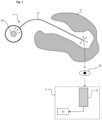
- the invention relates to a device 3 for diagnosing the functioning of a light implant 1 intended to be implanted in the brain 2 of a living being.
- this light implant 1 is intended to emit light to at least one area of the brain 2 of the living being.
- light or light signal we mean any electromagnetic radiation which goes from ultraviolet to far infrared via the visible.
- the implant 1 uses at least one light source 10 and comprises a probe 11 through which the light is diffused.
- the probe 11 may be in the form of an optical fiber responsible for conveying the light from the light source 10 to its distal end, located close to the tissues to be treated.
- the principle of production of the implant may be varied.
- Patent applications EP3302687A1 , EP3723851A1 And EP3834884A1 describe such intracranial probes.
- implant we mean that the device has at least one part implanted in the brain of the living being, even if it may possibly have parts located outside the body of the living being.
- the objective of the diagnostic device 3 is to determine the operating state of the light implant 1 placed inside the skull of the living being by detecting the presence or absence of a light signal S transmitted through the eye 20 of the living being.
- the diagnostic device 3 has the particularity of being non-invasive, that is to say that it is placed outside the body of the living being.
- the receiver 31 is configured to collect the photons emitted by the light implant 1 and which are scattered by the tissues and exit via the eyeball.
- the receiver 31 must be able to measure very low optical powers (between femtoWatt and nanoWatt) and with sufficiently short integration times (of the order of a minute or less) so that the examination is compatible with a measurement on a living being.
- the receiver 31 may in particular be a commercial multi-pixel photon counting detector, based on avalanche photodiodes in Geiger mode, or a large diameter silicon photodiode allowing a strong solid angle of detection.
- This type of detector does not provide an image, but a point value; however, their sensitivity can be much higher than that of a camera, and they are more compact and faster. It is possible to add a lens with a large numerical aperture in front of the detector, to collect the most photons. This lens then plays the role of a condenser.
- the observation must be carried out with a minimum of stray light.
- the observation is advantageously carried out in conditions of total darkness to avoid any light pollution due to the environment.
- the ambient light level must be at least one order of magnitude lower than that of the light signal transmitted through the eye.
- data representative of a light signal we mean a maximum light intensity, for example taken at the level of one or more pixels of the captured image (by the camera), an average of several measured light intensities... Any other data could be considered.
- the means 32 for determining the operating state of a light implant 1 can conclude that the light implant 1 is defective. If one or more of the data from the second signal received differ from those representative of the first signal, the means 32 for determining can conclude that the light implant 1 is functional. It is possible to set a threshold above which the means 32 for determining the operating state of the implant determine that one or more of the data from the second signal differ sufficiently from those representative of the first signal.
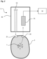
- the mechanical support is in the form of an optical plate 30 on which the receiver 31, for example the camera, is fixed opposite one of the two eyes (for example the eye 20) of the living being.
- the optical plate 30 can be movable on several axes in order to be able to adapt the position of the camera opposite the targeted eye. It can be equipped with a chin rest (not shown) to stabilize the head of the living being opposite the system.
- a point light source 33 will be positioned in front of the other eye 21, to ensure that the living being maintains its gaze immobile: the living being fixes this point of light with one eye 21, and the camera observes the other eye 20.
- an intracerebral light implant 1 is used, made in the form of an optical fiber implanted in the brain 2, so that the end of the optical fiber is located between the two black substances, at the level of the midbrain and therefore close to the optic chiasm.
- the light implant 1 has, for example, a peak power of 15 mW, the light being pulsed with a duty cycle of 8%. Dilation of the pupil is not necessary. The room is completely dark, and the patient is positioned on the chin rest of the support.
- the light source 33 allowing the gaze to be fixed emits at a certain wavelength (green for example, 550 nm) while the receiver 31 (camera or detector) observing the other eye 20 is only sensitive to the emission wavelength of the light implant 1 (for example by means of a high-pass filter which would only allow wavelengths greater than 600 nm to pass).
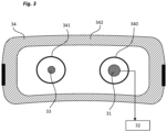
- the mechanical support comes in the form of a mask 34 to be applied around the head of the living being.
- the mask 34 carries two glasses 340, 341 intended to be placed respectively opposite the two eyes 20, 21 of the living being, one glass carrying the receiver 31 (detector or camera) and one glass carrying the light source 33 used to capture the gaze of the living being.
- the mask 34 comprises occultation means 342, used to create a channel isolated from any light pollution between the first eye 20 of the living being and the capture zone of the receiver 31 and between the light source 33 and the second eye 21 of the living being.
- This embodiment may have an adapter to allow the light source 33 and the receiver 31 to be interchanged, and thus to be able to observe the right eye or the left eye of the living being.
- both the transmitter and the sensor may be on the same eye, or even on both eyes.
- the distance between the light source and the point detector could be adjusted to adapt to the interocular distance of the patient.
- the pulsed signal from the optical stimulation device (for example detected electrically by induction on the laser power cable, or optically with a photodetector at the level of the skull, or digitally in RF) is then used as an external source to exacerbate the optical signal measured via the eye.
- the external source can also come from a second optical detector placed on the patient's skull, at the level of the pulsed light source, on the scalp. A detector measures the signal diffused via the scalp, this signal acting as a carrier to increase the signal-to-noise ratio of the detector observing the eye, as for synchronous detection.
Landscapes
- Health & Medical Sciences (AREA)
- Engineering & Computer Science (AREA)
- Biomedical Technology (AREA)
- Life Sciences & Earth Sciences (AREA)
- Pathology (AREA)
- Animal Behavior & Ethology (AREA)
- General Health & Medical Sciences (AREA)
- Public Health (AREA)
- Veterinary Medicine (AREA)
- Nuclear Medicine, Radiotherapy & Molecular Imaging (AREA)
- Radiology & Medical Imaging (AREA)
- Physics & Mathematics (AREA)
- Biophysics (AREA)
- General Physics & Mathematics (AREA)
- Spectroscopy & Molecular Physics (AREA)
- Heart & Thoracic Surgery (AREA)
- Medical Informatics (AREA)
- Molecular Biology (AREA)
- Surgery (AREA)
- Neurosurgery (AREA)
- Measurement Of The Respiration, Hearing Ability, Form, And Blood Characteristics Of Living Organisms (AREA)
- Investigating Or Analysing Materials By Optical Means (AREA)
- Measurement And Recording Of Electrical Phenomena And Electrical Characteristics Of The Living Body (AREA)
- Measuring And Recording Apparatus For Diagnosis (AREA)
Claims (12)
- Verfahren zur Bestimmung des Betriebszustands eines Lichtimplantats (1), das in das Gehirn (2) eines Lebewesens implantiert ist, wobei das Lichtimplantat (1) eine Lichtquelle (10) umfasst, welche die Aufgabe hat, Licht in das Gehirn des Lebewesens zu emittieren, wobei das Verfahren eine Diagnosevorrichtung (3) einsetzt, die einen Empfänger (31) für ein Lichtsignal umfasst, das durch ein erstes Auge (20) des Lebewesens hindurch übertragen wird, und Mittel zur Bestimmung des Betriebszustands des Lichtimplantats (1) ausgehend von dem empfangenen übertragenen Lichtsignal,
dadurch gekennzeichnet, dass es umfasst:- einen Schritt des Positionierens des Empfängers (31) der Diagnosevorrichtung gegenüber dem ersten Auge (20) des Lebewesens,- einen Schritt des Messens eines Lichtsignals, das von dem Empfänger (31) empfangen wird, wenn das Lichtimplantat (1) aktiviert ist,- einen Schritt des Vergleichens zwischen den Daten, die für das von dem Empfänger (31) empfangene Lichtsignal repräsentativ sind, und mindestens einem Referenzdatenelement,- einen Schritt des Bestimmens des Betriebszustands des Lichtimplantats (1) unter einem betriebsfähigen Zustand und einem nicht betriebsfähigen Zustand unter Berücksichtigung des Ergebnisses des Schritts des Vergleichens. - Verfahren nach Anspruch 1, dadurch gekennzeichnet, dass das Referenzdatenelement bei einem Schritt des Kalibrierens der Diagnosevorrichtung (3) vorgespeichert oder erfasst wird.
- Verfahren nach Anspruch 2, dadurch gekennzeichnet, dass der Schritt des Kalibrierens in einem Schritt des Messens eines Referenzlichtsignals besteht, der ausgeführt wird, wenn das Lichtimplantat (1) deaktiviert ist.
- Verfahren nach einem der Ansprüche 1 bis 3, dadurch gekennzeichnet, dass der Schritt des Bestimmens des Betriebszustands des Lichtimplantats (1) darin besteht, mindestens eine Abweichung zwischen dem Referenzdatenelement und einem Datenelement der Daten, die für das empfangene Lichtsignal repräsentativ sind, zu bestimmen und die Abweichung mit einem vorbestimmten Schwellenwert zu vergleichen.
- Verfahren nach einem der Ansprüche 1 bis 4, dadurch gekennzeichnet, dass es einen Schritt des Positionierens einer punktförmigen Lichtquelle (33) gegenüber einem zweiten Auge (21) des Lebewesens und einen Schritt des Aktivierens der punktförmigen Lichtquelle (33) umfasst.
- Diagnosevorrichtung (3), die dazu eingesetzt wird, das in einem der Ansprüche 1 bis 5 definierte Verfahren umzusetzen, dadurch gekennzeichnet, dass sie einen mechanischen Halter (30, 34) umfasst, an dem der Empfänger (31) befestigt ist, und Mittel (32) zum Bestimmen des Betriebszustands des Lichtimplantats (1), die mit dem Empfänger (31) verbunden sind und dazu ausgestaltet sind, von dem Empfänger kommende Daten zu verarbeiten.
- Vorrichtung nach Anspruch 6, dadurch gekennzeichnet, dass der Empfänger (31) eine Kamera ist.
- Vorrichtung nach Anspruch 6, dadurch gekennzeichnet, dass der Empfänger (31) eine oder mehrere Fotodioden umfasst.
- Vorrichtung nach einem der Ansprüche 6 bis 8, dadurch gekennzeichnet, dass sie eine punktförmige Lichtquelle (33) umfasst, die an dem Halter befestigt ist und dazu bestimmt ist, gegenüber einem zweiten Auge (21) des Lebewesens, parallel zu dem Empfänger (31), angeordnet zu werden.
- Diagnosevorrichtung nach Anspruch 6, dadurch gekennzeichnet, dass der mechanische Halter eine optische Platte (30) umfasst, die mit einem Kinnriemen versehen ist und an welcher der Empfänger (31) befestigt ist.
- Vorrichtung nach Anspruch 6, dadurch gekennzeichnet, dass der mechanische Halter eine Maske (34) umfasst, die um den Kopf des Lebewesens herum anzulegen ist.
- Vorrichtung nach Anspruch 11, dadurch gekennzeichnet, dass die Maske (34) zwei Lünetten umfasst, eine erste Lünette (340), die den Empfänger (31) aufnimmt, und eine zweite Lünette (341), die eine punktförmige Lichtquelle (33) aufnimmt.
Applications Claiming Priority (1)
| Application Number | Priority Date | Filing Date | Title |
|---|---|---|---|
| FR2209903A FR3140285B1 (fr) | 2022-09-29 | 2022-09-29 | Procédé et de détermination de l'état de fonctionnement d'un implant lumineux |
Publications (2)
| Publication Number | Publication Date |
|---|---|
| EP4344729A1 EP4344729A1 (de) | 2024-04-03 |
| EP4344729B1 true EP4344729B1 (de) | 2025-06-25 |
Family
ID=84331143
Family Applications (1)
| Application Number | Title | Priority Date | Filing Date |
|---|---|---|---|
| EP23198137.4A Active EP4344729B1 (de) | 2022-09-29 | 2023-09-19 | Verfahren und vorrichtung zur bestimmung des betriebszustandes eines lichtimplantats |
Country Status (3)
| Country | Link |
|---|---|
| US (1) | US12498266B2 (de) |
| EP (1) | EP4344729B1 (de) |
| FR (1) | FR3140285B1 (de) |
Family Cites Families (16)
| Publication number | Priority date | Publication date | Assignee | Title |
|---|---|---|---|---|
| US8706243B2 (en) * | 2009-02-09 | 2014-04-22 | Rainbow Medical Ltd. | Retinal prosthesis techniques |
| JP2012095803A (ja) * | 2010-11-01 | 2012-05-24 | Nara Institute Of Science & Technology | 生体光双方向情報交換システム及び該システムの制御方法 |
| US9004687B2 (en) * | 2012-05-18 | 2015-04-14 | Sync-Think, Inc. | Eye tracking headset and system for neuropsychological testing including the detection of brain damage |
| US10219696B2 (en) * | 2013-03-07 | 2019-03-05 | The Board Of Trustees Of The Leland Stanford Junior University | Implantable pressure sensors for telemetric measurements through bodily tissues |
| WO2014153428A1 (en) | 2013-03-19 | 2014-09-25 | Surgisense Corporation | Apparatus, systems and methods for determining tissue oxygenation |
| FR3036623B1 (fr) | 2015-05-28 | 2017-05-19 | Commissariat Energie Atomique | Dispositif pour stimulation electrique et optique profonde du cerveau |
| FR3045821B1 (fr) * | 2015-12-17 | 2018-11-23 | Commissariat A L'energie Atomique Et Aux Energies Alternatives | Dispositif de detection d'une fuite dans une enceinte hermetique |
| WO2018160711A1 (en) | 2017-02-28 | 2018-09-07 | Amo Wavefront Sciences, Llc | Method and system for pupil retro illumination using sample arm of oct interferometer |
| WO2019115909A1 (fr) | 2017-12-11 | 2019-06-20 | Commissariat A L'Énergie Atomique Et Aux Energies Alternatives | Dispositif d'illumination localisée implantable à architecture améliorée |
| JP7491218B2 (ja) * | 2018-10-10 | 2024-05-28 | 株式会社ニデック | 眼科装置、および眼科装置制御プログラム |
| ES2916713T3 (es) * | 2018-10-30 | 2022-07-05 | Inst De Fisica Daltes Energies | Sistema de visión artificial |
| DE102019114537A1 (de) * | 2019-05-29 | 2020-12-03 | OSRAM Opto Semiconductors Gesellschaft mit beschränkter Haftung | Optoelektronisches sensorbauelement zur lichtmessung mit eingebauter redundanz |
| EP4041374A4 (de) * | 2019-10-04 | 2024-01-24 | Nalu Medical, Inc. | Stimulationsvorrichtung |
| FR3104449B1 (fr) | 2019-12-12 | 2021-12-24 | Commissariat Energie Atomique | Dispositif d'illumination implantable dans un être vivant |
| FR3104448B1 (fr) * | 2019-12-12 | 2022-08-26 | Commissariat Energie Atomique | Dispositif d'illumination implantable dans un être vivant |
| US11395620B1 (en) | 2021-06-03 | 2022-07-26 | Ofer Moshe | Methods and systems for transformation between eye images and digital images |
-
2022
- 2022-09-29 FR FR2209903A patent/FR3140285B1/fr active Active
-
2023
- 2023-09-19 EP EP23198137.4A patent/EP4344729B1/de active Active
- 2023-09-28 US US18/476,487 patent/US12498266B2/en active Active
Also Published As
| Publication number | Publication date |
|---|---|
| FR3140285A1 (fr) | 2024-04-05 |
| FR3140285B1 (fr) | 2024-08-30 |
| US20240110828A1 (en) | 2024-04-04 |
| EP4344729A1 (de) | 2024-04-03 |
| US12498266B2 (en) | 2025-12-16 |
Similar Documents
| Publication | Publication Date | Title |
|---|---|---|
| EP2670294B1 (de) | Verfahren und vorrichtung für hochauflösende retinabildgebung | |
| EP2351518B1 (de) | Perioperative bispektrale optische Sonde | |
| EP1875209B1 (de) | Fluoreszenzabbildungsvorrichtung mit Reflexion bei zwei Wellenlängen | |
| FR3036187B1 (fr) | Procede de correction d’une image de fluorescence | |
| EP2309249B1 (de) | Vorrichtung und Verfahren zur gestreuten Erregung in der Bildgebung | |
| FR2699677A1 (fr) | Procédé et dispositif de détermination de la couleur d'un objet transparent, diffusant et absorbant, tel en particulier qu'une dent. | |
| US20150245768A1 (en) | Optical probe, optical measurement method, and optical measurement device | |
| EP3614904B1 (de) | System und verfahren zur multiskaligen netzhautbildgebung | |
| EP2555667B1 (de) | Optisches system zur verfolgung der augenbewegung und zugehörige trägervorrichtung | |
| EP4344729B1 (de) | Verfahren und vorrichtung zur bestimmung des betriebszustandes eines lichtimplantats | |
| FR3087539A1 (fr) | Instrument de mesure avec systeme de visualisation du spot de mesure et accessoire de visualisation pour un tel instrument de mesure | |
| FR3032527A1 (fr) | Dispositif de mesure d'un signal optique retrodiffuse par un echantillon | |
| WO2007118954A1 (fr) | Microscopie de fluorescence fibree a base de bleu de methylene | |
| EP2677920B1 (de) | Verfahren und vorrichtung für hochauflösende retinabildgebung | |
| FR2612391A1 (fr) | Dispositif d'observation de l'oeil utilisant la reflexion infrarouge sur le globe oculaire | |
| FR3126318A1 (fr) | Dispositif implantable d'illumination cérébrale à solution de surveillance de sonde optique | |
| CA3184950A1 (fr) | Appareil de determination du taux d'hemoglobine ou d'hematocrite d'un liquide en circulation | |
| FR3106740A1 (fr) | Procédés et systèmes de contrôle de l’alignement de l’œil dans un appareil d’imagerie ophtalmologique | |
| FR2708735A1 (fr) | Dispositif permettant l'évaluation des effets de la lumière sur la peau et son application à la détection de pathologies de la peau. | |
| FR3153981A1 (fr) | Dispositif d’acquisition de données oculaires et ensemble pour l’acquisition de données oculaires | |
| WO2019207253A1 (fr) | Systeme de photocoagulation laser d'une retine | |
| EP4322830A1 (de) | Vorrichtung und verfahren zur abbildung mobiler ziele | |
| FR3095519A1 (fr) | Procédé non-invasif de détermination du genre d'un œuf | |
| FR3000660A1 (fr) | Dispositif de detection et de visualisation peroperatoire |
Legal Events
| Date | Code | Title | Description |
|---|---|---|---|
| PUAI | Public reference made under article 153(3) epc to a published international application that has entered the european phase |
Free format text: ORIGINAL CODE: 0009012 |
|
| STAA | Information on the status of an ep patent application or granted ep patent |
Free format text: STATUS: REQUEST FOR EXAMINATION WAS MADE |
|
| 17P | Request for examination filed |
Effective date: 20230919 |
|
| AK | Designated contracting states |
Kind code of ref document: A1 Designated state(s): AL AT BE BG CH CY CZ DE DK EE ES FI FR GB GR HR HU IE IS IT LI LT LU LV MC ME MK MT NL NO PL PT RO RS SE SI SK SM TR |
|
| RAP3 | Party data changed (applicant data changed or rights of an application transferred) |
Owner name: UNIVERSITE GRENOBLE ALPES Owner name: CENTRE HOSPITALIER UNIVERSITAIRE GRENOBLE ALPES Owner name: COMMISSARIAT A L'ENERGIE ATOMIQUE ET AUX ENERGIESALTERNATIVES |
|
| GRAP | Despatch of communication of intention to grant a patent |
Free format text: ORIGINAL CODE: EPIDOSNIGR1 |
|
| STAA | Information on the status of an ep patent application or granted ep patent |
Free format text: STATUS: GRANT OF PATENT IS INTENDED |
|
| RIC1 | Information provided on ipc code assigned before grant |
Ipc: A61B 5/00 20060101ALI20250203BHEP Ipc: A61N 5/06 20060101AFI20250203BHEP |
|
| INTG | Intention to grant announced |
Effective date: 20250213 |
|
| GRAS | Grant fee paid |
Free format text: ORIGINAL CODE: EPIDOSNIGR3 |
|
| GRAA | (expected) grant |
Free format text: ORIGINAL CODE: 0009210 |
|
| STAA | Information on the status of an ep patent application or granted ep patent |
Free format text: STATUS: THE PATENT HAS BEEN GRANTED |
|
| AK | Designated contracting states |
Kind code of ref document: B1 Designated state(s): AL AT BE BG CH CY CZ DE DK EE ES FI FR GB GR HR HU IE IS IT LI LT LU LV MC ME MK MT NL NO PL PT RO RS SE SI SK SM TR |
|
| REG | Reference to a national code |
Ref country code: GB Ref legal event code: FG4D Free format text: NOT ENGLISH |
|
| REG | Reference to a national code |
Ref country code: CH Ref legal event code: EP |
|
| REG | Reference to a national code |
Ref country code: DE Ref legal event code: R096 Ref document number: 602023004272 Country of ref document: DE |
|
| REG | Reference to a national code |
Ref country code: CH Ref legal event code: EP |
|
| REG | Reference to a national code |
Ref country code: IE Ref legal event code: FG4D Free format text: LANGUAGE OF EP DOCUMENT: FRENCH |
|
| PG25 | Lapsed in a contracting state [announced via postgrant information from national office to epo] |
Ref country code: FI Free format text: LAPSE BECAUSE OF FAILURE TO SUBMIT A TRANSLATION OF THE DESCRIPTION OR TO PAY THE FEE WITHIN THE PRESCRIBED TIME-LIMIT Effective date: 20250625 |
|
| PGFP | Annual fee paid to national office [announced via postgrant information from national office to epo] |
Ref country code: DE Payment date: 20250919 Year of fee payment: 3 |
|
| REG | Reference to a national code |
Ref country code: LT Ref legal event code: MG9D |
|
| PG25 | Lapsed in a contracting state [announced via postgrant information from national office to epo] |
Ref country code: NO Free format text: LAPSE BECAUSE OF FAILURE TO SUBMIT A TRANSLATION OF THE DESCRIPTION OR TO PAY THE FEE WITHIN THE PRESCRIBED TIME-LIMIT Effective date: 20250925 Ref country code: GR Free format text: LAPSE BECAUSE OF FAILURE TO SUBMIT A TRANSLATION OF THE DESCRIPTION OR TO PAY THE FEE WITHIN THE PRESCRIBED TIME-LIMIT Effective date: 20250926 |
|
| PG25 | Lapsed in a contracting state [announced via postgrant information from national office to epo] |
Ref country code: BG Free format text: LAPSE BECAUSE OF FAILURE TO SUBMIT A TRANSLATION OF THE DESCRIPTION OR TO PAY THE FEE WITHIN THE PRESCRIBED TIME-LIMIT Effective date: 20250625 |
|
| PG25 | Lapsed in a contracting state [announced via postgrant information from national office to epo] |
Ref country code: HR Free format text: LAPSE BECAUSE OF FAILURE TO SUBMIT A TRANSLATION OF THE DESCRIPTION OR TO PAY THE FEE WITHIN THE PRESCRIBED TIME-LIMIT Effective date: 20250625 |
|
| PGFP | Annual fee paid to national office [announced via postgrant information from national office to epo] |
Ref country code: AT Payment date: 20251020 Year of fee payment: 3 Ref country code: FR Payment date: 20250917 Year of fee payment: 3 |
|
| PG25 | Lapsed in a contracting state [announced via postgrant information from national office to epo] |
Ref country code: RS Free format text: LAPSE BECAUSE OF FAILURE TO SUBMIT A TRANSLATION OF THE DESCRIPTION OR TO PAY THE FEE WITHIN THE PRESCRIBED TIME-LIMIT Effective date: 20250925 |
|
| PG25 | Lapsed in a contracting state [announced via postgrant information from national office to epo] |
Ref country code: LV Free format text: LAPSE BECAUSE OF FAILURE TO SUBMIT A TRANSLATION OF THE DESCRIPTION OR TO PAY THE FEE WITHIN THE PRESCRIBED TIME-LIMIT Effective date: 20250625 |
|
| REG | Reference to a national code |
Ref country code: NL Ref legal event code: MP Effective date: 20250625 |
|
| PG25 | Lapsed in a contracting state [announced via postgrant information from national office to epo] |
Ref country code: NL Free format text: LAPSE BECAUSE OF FAILURE TO SUBMIT A TRANSLATION OF THE DESCRIPTION OR TO PAY THE FEE WITHIN THE PRESCRIBED TIME-LIMIT Effective date: 20250625 |
|
| PG25 | Lapsed in a contracting state [announced via postgrant information from national office to epo] |
Ref country code: PT Free format text: LAPSE BECAUSE OF FAILURE TO SUBMIT A TRANSLATION OF THE DESCRIPTION OR TO PAY THE FEE WITHIN THE PRESCRIBED TIME-LIMIT Effective date: 20251027 |
|
| REG | Reference to a national code |
Ref country code: AT Ref legal event code: MK05 Ref document number: 1805871 Country of ref document: AT Kind code of ref document: T Effective date: 20250625 |
|
| PG25 | Lapsed in a contracting state [announced via postgrant information from national office to epo] |
Ref country code: IS Free format text: LAPSE BECAUSE OF FAILURE TO SUBMIT A TRANSLATION OF THE DESCRIPTION OR TO PAY THE FEE WITHIN THE PRESCRIBED TIME-LIMIT Effective date: 20251025 |
|
| PG25 | Lapsed in a contracting state [announced via postgrant information from national office to epo] |
Ref country code: AT Free format text: LAPSE BECAUSE OF FAILURE TO SUBMIT A TRANSLATION OF THE DESCRIPTION OR TO PAY THE FEE WITHIN THE PRESCRIBED TIME-LIMIT Effective date: 20250625 Ref country code: SM Free format text: LAPSE BECAUSE OF FAILURE TO SUBMIT A TRANSLATION OF THE DESCRIPTION OR TO PAY THE FEE WITHIN THE PRESCRIBED TIME-LIMIT Effective date: 20250625 |
|
| PG25 | Lapsed in a contracting state [announced via postgrant information from national office to epo] |
Ref country code: CZ Free format text: LAPSE BECAUSE OF FAILURE TO SUBMIT A TRANSLATION OF THE DESCRIPTION OR TO PAY THE FEE WITHIN THE PRESCRIBED TIME-LIMIT Effective date: 20250625 |
|
| PG25 | Lapsed in a contracting state [announced via postgrant information from national office to epo] |
Ref country code: PL Free format text: LAPSE BECAUSE OF FAILURE TO SUBMIT A TRANSLATION OF THE DESCRIPTION OR TO PAY THE FEE WITHIN THE PRESCRIBED TIME-LIMIT Effective date: 20250625 |
|
| PG25 | Lapsed in a contracting state [announced via postgrant information from national office to epo] |
Ref country code: EE Free format text: LAPSE BECAUSE OF FAILURE TO SUBMIT A TRANSLATION OF THE DESCRIPTION OR TO PAY THE FEE WITHIN THE PRESCRIBED TIME-LIMIT Effective date: 20250625 |
|
| PG25 | Lapsed in a contracting state [announced via postgrant information from national office to epo] |
Ref country code: SK Free format text: LAPSE BECAUSE OF FAILURE TO SUBMIT A TRANSLATION OF THE DESCRIPTION OR TO PAY THE FEE WITHIN THE PRESCRIBED TIME-LIMIT Effective date: 20250625 |
|
| PG25 | Lapsed in a contracting state [announced via postgrant information from national office to epo] |
Ref country code: ES Free format text: LAPSE BECAUSE OF FAILURE TO SUBMIT A TRANSLATION OF THE DESCRIPTION OR TO PAY THE FEE WITHIN THE PRESCRIBED TIME-LIMIT Effective date: 20250625 |
|
| PG25 | Lapsed in a contracting state [announced via postgrant information from national office to epo] |
Ref country code: RO Free format text: LAPSE BECAUSE OF FAILURE TO SUBMIT A TRANSLATION OF THE DESCRIPTION OR TO PAY THE FEE WITHIN THE PRESCRIBED TIME-LIMIT Effective date: 20250625 |