EP4344591B1 - Appareil de cuisson avec poignee de prehension rotative - Google Patents
Appareil de cuisson avec poignee de prehension rotative Download PDFInfo
- Publication number
- EP4344591B1 EP4344591B1 EP23200547.0A EP23200547A EP4344591B1 EP 4344591 B1 EP4344591 B1 EP 4344591B1 EP 23200547 A EP23200547 A EP 23200547A EP 4344591 B1 EP4344591 B1 EP 4344591B1
- Authority
- EP
- European Patent Office
- Prior art keywords
- cooking
- cooking appliance
- handling part
- mode
- user interface
- Prior art date
- Legal status (The legal status is an assumption and is not a legal conclusion. Google has not performed a legal analysis and makes no representation as to the accuracy of the status listed.)
- Active
Links
Images


Classifications
-
- A—HUMAN NECESSITIES
- A47—FURNITURE; DOMESTIC ARTICLES OR APPLIANCES; COFFEE MILLS; SPICE MILLS; SUCTION CLEANERS IN GENERAL
- A47J—KITCHEN EQUIPMENT; COFFEE MILLS; SPICE MILLS; APPARATUS FOR MAKING BEVERAGES
- A47J37/00—Baking; Roasting; Grilling; Frying
- A47J37/06—Roasters; Grills; Sandwich grills
- A47J37/0623—Small-size cooking ovens, i.e. defining an at least partially closed cooking cavity
- A47J37/0664—Accessories
-
- A—HUMAN NECESSITIES
- A47—FURNITURE; DOMESTIC ARTICLES OR APPLIANCES; COFFEE MILLS; SPICE MILLS; SUCTION CLEANERS IN GENERAL
- A47J—KITCHEN EQUIPMENT; COFFEE MILLS; SPICE MILLS; APPARATUS FOR MAKING BEVERAGES
- A47J37/00—Baking; Roasting; Grilling; Frying
- A47J37/06—Roasters; Grills; Sandwich grills
- A47J37/0611—Roasters; Grills; Sandwich grills the food being cooked between two heating plates, e.g. waffle-irons
-
- A—HUMAN NECESSITIES
- A47—FURNITURE; DOMESTIC ARTICLES OR APPLIANCES; COFFEE MILLS; SPICE MILLS; SUCTION CLEANERS IN GENERAL
- A47J—KITCHEN EQUIPMENT; COFFEE MILLS; SPICE MILLS; APPARATUS FOR MAKING BEVERAGES
- A47J37/00—Baking; Roasting; Grilling; Frying
- A47J37/06—Roasters; Grills; Sandwich grills
- A47J37/0623—Small-size cooking ovens, i.e. defining an at least partially closed cooking cavity
- A47J37/0629—Small-size cooking ovens, i.e. defining an at least partially closed cooking cavity with electric heating elements
-
- A—HUMAN NECESSITIES
- A47—FURNITURE; DOMESTIC ARTICLES OR APPLIANCES; COFFEE MILLS; SPICE MILLS; SUCTION CLEANERS IN GENERAL
- A47J—KITCHEN EQUIPMENT; COFFEE MILLS; SPICE MILLS; APPARATUS FOR MAKING BEVERAGES
- A47J45/00—Devices for fastening or gripping kitchen utensils or crockery
- A47J45/06—Handles for hollow-ware articles
Definitions
- the present invention relates generally to a cooking appliance for cooking food products, and in particular to an electric cooking appliance capable of operating in a grill mode and a barbecue mode.
- the electric cooking appliance as known in the prior art can alternately occupy the "grill” mode in which a food is intended to be enclosed and cooked between the first and second cooking plates, and the "barbecue” mode in which the first and second cooking plates are spaced apart at 180° so as to be substantially in the same plane, said plane being generally horizontal when the cooking appliance rests on a horizontal surface.
- the cooking appliance as described in the prior art advantageously allows a single household appliance to be used to fulfill two distinct functions: that of a food grill, and that of a barbecue.
- the integration of the user interface in the first structure i.e. on the lower part of the electric cooking appliance, has the disadvantage of improved ergonomics due to the restricted physical access as well as the limited visibility of the user on the user interface. Also, such an arrangement of the user interface prevents the collection of cooking juices from a front face of the first structure.
- the technical problem underlying the invention consists in particular in providing a cooking appliance allowing the cooking of food products in a grill configuration but also in a barbecue configuration, while being ergonomic and simple to use and while possibly allowing the collection of cooking juices from a front face of the first structure.
- the cooking appliance may further have one or more of the following characteristics, taken alone or in combination.
- the second structure occupies the maximum open position when the cooking appliance is in the second mode of use.
- the cooking appliance is configured such that the first cooking plate and the second cooking plate define a first angle of inclination of between 150 and 200°, advantageously between 170 and 190° and for example approximately 180°, when the second structure occupies the maximum open position.
- the handling part is elongated and extends along an extension axis substantially parallel to the pivot axis.
- the pivot axis is substantially horizontal when the cooking appliance rests on a horizontal surface.
- the handling part comprises a front provided with a main surface which is substantially planar and on which the user interface is provided.
- the cooking appliance is configured such that the main surface is inclined at an angle of inclination of between 30° and 60°, and advantageously between 40° and 50°, relative to a vertical plane, when the cooking appliance rests on a horizontal surface, the second structure is in the closed position and the handling part is in the first position of use.
- the cooking appliance is configured such that the main surface is inclined at an inclination angle between 30° and 60°, and advantageously between 40° and 50°, relative to a vertical plane, when the cooking appliance rests on a horizontal surface, the second structure is in the maximum opening position and the handling part is in the second position of use.
- the handling portion is configured to extend substantially horizontally when the cooking appliance rests on a horizontal surface.
- the handling part delimits an internal housing in which an electronic card associated with the user interface is housed.
- the handling part comprises a housing to which the front panel is fixed, the housing and the front panel delimiting the internal housing.
- the handling part is mounted to be able to rotate around an axis of rotation.
- the first position of use and the second position of use are angularly offset from each other by approximately 90°.
- the axis of rotation is substantially parallel to the pivot axis.
- the second structure comprises at least one connecting arm connected to the pivot connection, the handling part being supported by the at least one connecting arm and being mounted to be able to rotate relative to the at least one connecting arm and around the axis of rotation.
- the second structure comprises two connecting arms connected to the pivot connection and configured to extend laterally on either side of the second cooking module, the handling part being supported by the two connecting arms and being mounted to be able to rotate relative to the two connecting arms and around the axis of rotation.
- the gripping handle comprises the two connecting arms and has a general U shape.
- the at least one connecting arm comprises a support portion which is generally cylindrical and the handling portion comprises a mounting portion provided with a receiving housing, the support portion being received in the receiving housing and being mounted to be able to rotate relative to the mounting portion around the axis of rotation.
- the support portion is tubular and comprises a central passage configured to allow the passage of an electrical power supply cable capable of electrically powering the user interface, or more particularly the electronic card associated with the user interface.
- the central passage is centered on the axis of rotation.
- the central passage is also configured to allow the passage of at least one connecting cable connecting the user interface to the control unit.
- the cooking appliance comprises at least one additional pivot connection configured to connect the second cooking module to the two connection arms, and to allow rotation of the second cooking module relative to the two connection arms around an additional pivot axis.
- the additional pivot axis is substantially parallel to the pivot axis.
- the cooking appliance further comprises an indexing system configured such that each of the first and second positions of use is stable.
- the indexing system comprises at least two indexing recesses provided on one of the handling part and a connecting arm, and at least one indexing member provided on the other of the handling part and the connecting arm, the at least one indexing member being configured to cooperate with a respective indexing recess when the handling part occupies respectively the first position of use or the second position of use.
- the indexing recesses are distributed around the axis of rotation.
- the at least one indexing member is formed by an indexing ball.
- the indexing ball is slidably mounted in a tubular receiving part which is provided on the handling part or the connecting arm.
- the indexing system comprises at least one biasing element configured to bias the indexing ball towards an indexing position.
- the indexing system comprises several indexing members distributed around the axis of rotation.
- the user interface is configured to display at least one display parameter according to a first orientation when the cooking appliance is in the first mode of use and the handling part is in the first position of use, and to display the at least one display parameter according to a second orientation which is different from the first orientation, and for example inverted, when the appliance cooking is in the second mode of use and the handling part is in the second position of use.
- the cooking appliance further comprises an electrical contact configured to occupy a first state when the cooking appliance is in the first mode of use, and configured to occupy a second state when the cooking appliance is in the second mode of use.
- the electrical contact is located in the first structure, and for example in a rear foot of the first structure.
- the electrical contact is located in the at least one connecting arm.
- the cooking appliance comprises an actuating device configured to move the electrical contact into the first state when the second structure is pivoted, from the maximum open position, towards the closed position and reaches a first predetermined position, and to move the electrical contact into the second state when the second structure is pivoted, from the closed position, towards the maximum open position and reaches a second predetermined position.
- the first and second predetermined positions are identical or different.
- the actuating device comprises an actuating member, such as an actuating finger for example, movable between an actuating position in which the actuating member is configured to activate the electrical contact and a position of release in which the actuating member is configured to deactivate the electrical contact.
- an actuating member such as an actuating finger for example, movable between an actuating position in which the actuating member is configured to activate the electrical contact and a position of release in which the actuating member is configured to deactivate the electrical contact.
- the actuating member is pivotally secured to the at least one connecting arm, and is for example provided on the at least one connecting arm.
- the actuating member is movable in translation.
- the actuating member is movable in rotation.
- the actuating device also comprises a cam configured to move the actuating member between the actuating position and the release position when the second structure reaches the first predetermined position or the second predetermined position.
- the user interface is configured to display the at least one display parameter according to the first orientation when the electrical contact occupies the first state, and is configured to display the at least one display parameter according to the second orientation when the electrical contact occupies the second state.
- the grip handle when the first structure rests on a horizontal surface and the second structure is in the maximum open position, then the grip handle is in contact with said horizontal surface.
- the second structure is capable of occupying an intermediate opening position which is stable and located between the closed position and the maximum opening position.
- the cooking appliance is configured such that the first cooking plate and the second cooking plate define a second tilt angle of between 90 and 120° when the second structure occupies the intermediate opening position.
- the first cooking plate is configured to be inclined downwardly and towards a front face of the first structure when the cooking appliance rests on the horizontal surface.
- the cooking appliance further comprises a cooking juice collection tray configured to collect cooking juices coming at least from the first cooking plate, the cooking juice collection tray being arranged at least partly under the first cooking module.
- the first cooking plate comprises a front spill portion which is provided on a front edge of the first cooking plate and which is located vertically in line with a front portion of the cooking juice collection tray, the front spill portion being configured to allow gravity flow of cooking juices from the first cooking plate into the cooking juice collection tray.
- the cooking appliance also comprises a kinematic chain mechanically connecting the handling part to the pivot connection, the kinematic chain being configured so as to move the handling part between the first and second positions of use depending on the position of the second structure relative to the first structure.
- the kinematic chain is provided at least partially in the at least one connecting arm.
- the kinematic chain comprises at least one drive element, such as a belt for example.
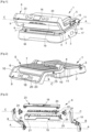
- THE figures 1 to 6 represent a cooking appliance 1 according to one embodiment of the invention.
- the cooking appliance 1 is configured for cooking food, such as meat, fish, vegetables or other food products.
- the cooking appliance 1 comprises a first structure 2 which comprises a first cooking module 3 which itself comprises a first cooking plate 4 and a first heating element (not shown in the figures) configured to heat the first cooking plate 4, and a second structure 5 which comprises a second cooking module 6 which itself comprises a second cooking plate 7 and a second heating element (not visible in the figures) configured to heat the second cooking plate 7.
- the first cooking plate 4 is configured to be inclined downwards and towards a front face of the first structure 2 when the cooking appliance 1 rests on a horizontal surface.
- the cooking appliance 1 has a first mode of use, called grill mode, in which a food is intended to be sandwiched between the first and second cooking plates 4, 7, and a second mode of use, called barbecue mode, in which each of the first and second cooking plates 4, 7 is capable of supporting and cooking a respective food.
- grill mode a first mode of use
- barbecue mode a second mode of use
- the second structure 5 further comprises a gripping handle 8 configured to support the second cooking module 6.
- the gripping handle 8 has a U shape, and comprises a handling portion 9 configured to be handled by a user, as well as two lateral connecting arms 10 configured to extend laterally on either side of the second cooking module 6 and to support the handling portion 9.
- the two connecting arms 10 are connected to a pivot connection 11.
- the first cooking plate 4 and the second cooking plate 7 define a first angle of inclination of between 150 and 200°, advantageously between 170 and 190° and for example approximately 180°, when the second structure 5 occupies the maximum opening position.
- first angle of inclination of between 150 and 200°, advantageously between 170 and 190° and for example approximately 180°, when the second structure 5 occupies the maximum opening position.
- the gripping handle 8 is in contact with said horizontal surface.
- the first cooking plate 4 and the second cooking plate 7 are substantially parallel when the second structure 5 is in the maximum open position, in order to offer the user a use of the cooking appliance 1 which is comparable to an electric barbecue.
- the first structure 2 also comprises feet 14 configured to rest on a flat support surface SA, such as a work surface.
- the cooking appliance 1 comprises an additional pivot connection 15 which is configured to connect the second cooking module 6 to the two connecting arms 10, and to allow rotation of the second cooking module 6 relative to the two connecting arms 10 around an additional pivot axis B which is substantially parallel to the pivot axis A.
- the additional pivot connection 15 makes it possible to position the second cooking module 6 according to the desired orientation, and generally substantially parallel to the first cooking module 3 when the second cooking module 6 is in one of the cooking positions.
- the second cooking module 6 is pivotally mounted relative to the gripping handle 8.
- the cooking appliance 1 also comprises a control unit 17 configured to control the operation of the cooking appliance 1.
- the control unit 17 may for example be arranged in the gripping handle 8 and in particular in the handling part 9, or even in the first structure 2.
- the handling part 9, which in particular has a user interface 18, is mounted to be movable in rotation relative to the two connecting arms 10 around an axis of rotation C and between at least a first position of use and a second position of use.
- the first position of use is dedicated to the first mode of use and allows the user interface 18 to be accessible to a user when the cooking appliance 1 is in the first mode of use
- the second position of use is dedicated to the second mode of use and allows the user interface 18 to be accessible to the user when the cooking appliance 1 is in the second mode of use.
- the first position of use and the second position of use are advantageously angularly offset from each other by approximately 90°.
- the handling part 9 is elongated and extends along the rotation axis C which is substantially parallel to the pivot axis A; which is also substantially horizontal when the cooking appliance 1 rests on a horizontal surface.
- the handling part 9 also comprises a housing 19 and a front panel 20 fixed to the housing 19.
- the housing 19 and the front panel 20 delimit an internal housing 21 in which an electronic card 22 associated with the user interface 18 is housed.
- the front panel 20 is provided with a main surface 23 which is substantially flat and on which the user interface 18 is provided.
- the cooking appliance 1 is configured such that the main surface 23 is inclined at an angle of inclination of between 30° and 60°, and advantageously between 40° and 50°, relative to a vertical plane, when the cooking appliance 1 rests on a horizontal surface, the second structure 5 is in the closed position and the handling part 9 is in the first position of use. Also, the cooking appliance 1 is configured such that the main surface 23 is inclined at an angle of inclination of between 30° and 60°, and advantageously between 40° and 50°, relative to a vertical plane, when the cooking appliance 1 rests on a horizontal surface, the second structure 5 is in the maximum open position and the handling part 9 is in the second position of use.
- the connecting arms 10 each comprise a support portion 24 which is generally cylindrical, and the handling part 9 comprises two mounting portions 25 each provided with a receiving housing.
- the support portion 24 of each connecting arm 10 is received in the respective receiving housing and is mounted to be rotatable relative to the respective mounting portion 25 around the axis of rotation C.
- each support portion 24 is tubular and comprises a central passage 26 which is centered on the axis of rotation C. At least one of the central passages 26 is configured to allow the passage of an electrical power supply cable capable of electrically powering the user interface 18, or more particularly the electronic card 22 associated with the user interface 18.
- the central passage 26 is also configured to allow the passage of at least one connecting cable connecting the electronic card 22, associated with the user interface 18, to the control unit 17.
- the cooking appliance 1 further comprises an indexing system 27 configured such that each of the first and second positions of use is stable.
- the indexing system 27 comprises for example two indexing recesses 28 provided on each of the two connecting arms 10, and an indexing member 29 provided on each of the end portions of the handling part 9.
- the indexing recesses 28 are distributed around the axis of rotation C.
- Each of the indexing members 29 is configured to cooperate with a respective indexing recess 28 when the handling part 9 occupies the first position of use and with a respective indexing recess 28 when the handling part 9 occupies the second position of use.
- each of the indexing members 29 is formed by an indexing ball 30.
- each of the indexing balls 30 is slidably mounted in a tubular receiving part 31 which is provided on the respective end portion of the handling part 9.
- the indexing system 27 comprises two biasing elements (not shown in the figures) each associated with a respective indexing member 29. Each biasing element is advantageously configured to bias the respective indexing ball 30 towards an indexing position.
- the cooking appliance 1 further comprises an electrical contact 32 configured to occupy a first state when the cooking appliance 1 is in the first mode of use, and configured to occupy a second state when the cooking appliance 1 is in the second mode of use.
- the electrical contact 32 is located in the first structure 2, and for example in a rear foot 14 of the first structure 2.
- the cooking appliance 1 also comprises an actuating device 33 configured to move the electrical contact 32 into the first state when the second structure 5 is pivoted, from the maximum opening position, towards the closing position and reaches a first predetermined position.
- the actuating device 33 is also configured to move the electrical contact 32 into the second state when the second structure 5 is pivoted, from the closing position, towards the maximum opening position and reaches a second predetermined position.
- the actuating device 33 comprises an actuating member 34, such as an actuating finger, which is configured to directly actuate the electrical contact 32.
- the actuating member 34 is mounted to be movable in rotation about the pivot axis A between an actuating position in which the actuating member 34 is configured to activate the electrical contact 32 and a release position in which the actuating member 34 is configured to deactivate the electrical contact 32.
- the actuating member 34 is pivotally secured to one of the connecting arms 10.
- the first and second predetermined positions are identical but could also be different according to other embodiments of the invention not shown.
- THE figures 7 And 8 represent a variant of the embodiment of the invention in which the electrical contact 32 is located in one of the connecting arms 10.
- the actuating device 33 comprises an actuating member 34, such as an actuating finger for example, which is mounted to move in translation between an actuating position in which the actuating member 34 is configured to activate the electrical contact 32 and a release position in which the actuating member 34 is configured to deactivate the electrical contact 32.
- the actuating member 34 is pivotally secured to one of the connecting arms 10, and is for example provided on said connecting arm 10.
- the actuating device 33 also comprises a cam 35 which is provided on the pivot connection 11 and which is static relative to the first structure 2. The cam 35 is configured to move the actuating member 34 between the actuating position and the release position when the second structure 5 reaches the first predetermined position or the second predetermined position.
- the user interface 18 is configured to display at least one display parameter according to a first orientation when the cooking appliance 1 is in the first mode of use and the handling part 9 is in the first position of use, and to display the at least one display parameter according to a second orientation which is different from the first orientation, and for example inverted, when the cooking appliance 1 is in the second mode of use and the handling part 9 is in the second position of use.
- the user interface 18 is configured to display the at least one display parameter according to the first orientation when the electrical contact 32 occupies the first state, and is configured to display the at least one display parameter according to the second orientation when the electrical contact 32 occupies the second state.
- the cooking appliance 1 further comprises a cooking juice collection tray 36.
- the cooking juice collection tray 36 is configured to collect cooking juices from the first plate cooking module 4 as well as the second cooking plate 7.
- the cooking juice collection tray 36 is arranged partly under the first cooking module 3.
- the first cooking plate 4 has a front overflow portion 37 which is provided on a front edge of the first cooking plate 4 and which is located vertically in line with a front portion of the cooking juice collection tray 36.
- the front overflow portion 37 is configured to allow gravity flow of the cooking juices from the first cooking plate 4 into the cooking juice collection tray 36.
- the cooking appliance 1 could further comprise a kinematic chain mechanically connecting the handling part 9 to the pivot connection 11 and being configured so as to move the handling part 9 around the axis of rotation C depending on the position of the second structure 5 relative to the first structure 2.
- the kinematic chain could be provided at least partially in one of the connecting arms 10 and comprise at least one drive element such as a belt for example.
Landscapes
- Engineering & Computer Science (AREA)
- Food Science & Technology (AREA)
- Baking, Grill, Roasting (AREA)
- Food-Manufacturing Devices (AREA)
Applications Claiming Priority (1)
| Application Number | Priority Date | Filing Date | Title |
|---|---|---|---|
| FR2210018A FR3140255B1 (fr) | 2022-09-30 | 2022-09-30 | Appareil de cuisson avec poignée de préhension rotative |
Publications (2)
| Publication Number | Publication Date |
|---|---|
| EP4344591A1 EP4344591A1 (fr) | 2024-04-03 |
| EP4344591B1 true EP4344591B1 (fr) | 2025-04-30 |
Family
ID=84568821
Family Applications (1)
| Application Number | Title | Priority Date | Filing Date |
|---|---|---|---|
| EP23200547.0A Active EP4344591B1 (fr) | 2022-09-30 | 2023-09-28 | Appareil de cuisson avec poignee de prehension rotative |
Country Status (6)
| Country | Link |
|---|---|
| EP (1) | EP4344591B1 (pl) |
| CN (1) | CN117796681B (pl) |
| CA (1) | CA3211130A1 (pl) |
| DK (1) | DK4344591T3 (pl) |
| FR (1) | FR3140255B1 (pl) |
| PL (1) | PL4344591T3 (pl) |
Families Citing this family (1)
| Publication number | Priority date | Publication date | Assignee | Title |
|---|---|---|---|---|
| ES3063460A1 (es) * | 2024-10-07 | 2026-04-16 | Mujica Julen Baz | Dispositivo de coccion de un producto alimenticio |
Family Cites Families (12)
| Publication number | Priority date | Publication date | Assignee | Title |
|---|---|---|---|---|
| US20070119442A1 (en) * | 2005-11-29 | 2007-05-31 | Wei-Teh Ho | Portable cooking device |
| CN101495018A (zh) * | 2006-06-09 | 2009-07-29 | 阳光有限责任公司 | 组合式烹饪压榨机和烤架 |
| US10321784B2 (en) * | 2009-07-10 | 2019-06-18 | Tsann Kuen (Zhangzhou) Enterprise Co., Ltd. | Grill device |
| PT106734B (pt) * | 2013-01-14 | 2020-09-01 | Novadelta - Comércio E Indústria De Cafés, Lda. | Máquina de preparação de bebidas com interface multifuncional e processo de operação da referida máquina |
| US9314133B2 (en) * | 2013-08-02 | 2016-04-19 | Conair Corporation | Grill plate and hinge structures |
| FR3050914B1 (fr) * | 2016-05-03 | 2019-08-23 | Seb Sa | Procede de configuration d’un appareil de cuisson par un terminal |
| EP3410016A1 (en) * | 2017-06-02 | 2018-12-05 | Electrolux Appliances Aktiebolag | User interface for a hob |
| FR3091159B1 (fr) * | 2019-01-01 | 2021-01-22 | Seb Sa | Appareil de cuisson electrique avec une fonction de marquage de l’aliment a cuire |
| US11647861B2 (en) * | 2020-03-30 | 2023-05-16 | Sharkninja Operating Llc | Cooking device and components thereof |
| CN113491450A (zh) * | 2020-04-06 | 2021-10-12 | 华高太平洋有限公司 | 烹饪器具 |
| CN212996102U (zh) * | 2020-10-10 | 2021-04-20 | 广东美的厨房电器制造有限公司 | 烹饪器具 |
| FR3117759B1 (fr) * | 2020-12-17 | 2022-12-30 | Seb Sa | Appareil de cuisson electrique pour la cuisson de produits alimentaires |
-
2022
- 2022-09-30 FR FR2210018A patent/FR3140255B1/fr active Active
-
2023
- 2023-09-01 CA CA3211130A patent/CA3211130A1/fr active Pending
- 2023-09-27 CN CN202311259545.XA patent/CN117796681B/zh active Active
- 2023-09-28 EP EP23200547.0A patent/EP4344591B1/fr active Active
- 2023-09-28 PL PL23200547.0T patent/PL4344591T3/pl unknown
- 2023-09-28 DK DK23200547.0T patent/DK4344591T3/da active
Also Published As
| Publication number | Publication date |
|---|---|
| FR3140255B1 (fr) | 2024-08-16 |
| CN117796681A (zh) | 2024-04-02 |
| FR3140255A1 (fr) | 2024-04-05 |
| CA3211130A1 (fr) | 2024-03-30 |
| CN117796681B (zh) | 2025-10-28 |
| EP4344591A1 (fr) | 2024-04-03 |
| PL4344591T3 (pl) | 2025-06-30 |
| DK4344591T3 (da) | 2025-06-10 |
Similar Documents
| Publication | Publication Date | Title |
|---|---|---|
| EP1491122B1 (fr) | Appareil électroménager | |
| EP3368376B1 (fr) | Console munie d'accoudoirs articules comprenant un mecanisme de deverrouillage perfectionne | |
| EP2675331B1 (fr) | Appareil electromenager de preparation culinaire comportant des moyens pour l'entrainement d'un outil de travail selon un mouvement planetaire | |
| EP4344591B1 (fr) | Appareil de cuisson avec poignee de prehension rotative | |
| EP3537940B1 (fr) | Appareil de cuisson pour la cuisson de produits alimentaires | |
| EP4014808B1 (fr) | Appareil de cuisson électrique pour la cuisson de produits alimentaires | |
| EP4344590B1 (fr) | Appareil de cuisson avec double interface utilisateur | |
| EP2651272B1 (fr) | Appareil électroménager de préparation culinaire comportant un socle supportant une cuve fermée par un couvercle amovible | |
| FR2892008A3 (fr) | Appareil a frire ou cuire inclinable | |
| EP3079544B1 (fr) | Appareil électroménager de préparation culinaire comportant un bras inférieur porté par un socle et un bras supérieur relié au bras inférieur par un dispositif d'articulation | |
| EP3079545B1 (fr) | Appareil électromenager de préparation culinaire comportant un socle, un bras inférieur et un bras supérieur monte pivotant sur le bras inférieur | |
| EP1370171B1 (fr) | Appareil electromenager de preparation culinaire comportant un outil rotatif et un double dispositif de securite | |
| FR2502533A1 (fr) | Machine a trancher les produits comestibles | |
| FR2623705A1 (pl) | ||
| EP2606786B1 (fr) | Appareil de cuisson avec sécurité de présence de plaques de chauffe | |
| EP4230099B1 (fr) | Appareil de cuisson electrique equipe d'un dispositif de mesure d' epaisseur | |
| FR2859815A1 (fr) | Dispositif de coupure de courant electrique a contact mobile en translation | |
| EP4154776B1 (fr) | Base d' appareil électroménager de préparation culinaire comprenant un volet de sécurité pivotant | |
| FR2855034A1 (fr) | Appareil electromenager comprenant deux plaques de cuisson a articulation decalee | |
| FR2610704A1 (fr) | Cuisiniere comportant notamment une plaque pivotante de protection | |
| EP3079543B1 (fr) | Appareil électroménager de préparation culinaire comportant un socle, un bras inférieur et un bras supérieur reliés entre eux par des dispositifs d'articulation | |
| CH469475A (fr) | Rôtissoire | |
| WO2024180299A1 (fr) | Appareil de cuisson electrique equipe d'une plaque de cuisson comprenant une nervure peripherique et une partie de deversement | |
| FR2876893A1 (fr) | Dispositif de traitement de produits alimentaires monte sur roulettes | |
| FR2734457A1 (fr) | Poste de travail ergonomique pour ordinateur |
Legal Events
| Date | Code | Title | Description |
|---|---|---|---|
| PUAI | Public reference made under article 153(3) epc to a published international application that has entered the european phase |
Free format text: ORIGINAL CODE: 0009012 |
|
| STAA | Information on the status of an ep patent application or granted ep patent |
Free format text: STATUS: THE APPLICATION HAS BEEN PUBLISHED |
|
| AK | Designated contracting states |
Kind code of ref document: A1 Designated state(s): AL AT BE BG CH CY CZ DE DK EE ES FI FR GB GR HR HU IE IS IT LI LT LU LV MC ME MK MT NL NO PL PT RO RS SE SI SK SM TR |
|
| STAA | Information on the status of an ep patent application or granted ep patent |
Free format text: STATUS: REQUEST FOR EXAMINATION WAS MADE |
|
| 17P | Request for examination filed |
Effective date: 20240926 |
|
| RBV | Designated contracting states (corrected) |
Designated state(s): AL AT BE BG CH CY CZ DE DK EE ES FI FR GB GR HR HU IE IS IT LI LT LU LV MC ME MK MT NL NO PL PT RO RS SE SI SK SM TR |
|
| GRAP | Despatch of communication of intention to grant a patent |
Free format text: ORIGINAL CODE: EPIDOSNIGR1 |
|
| STAA | Information on the status of an ep patent application or granted ep patent |
Free format text: STATUS: GRANT OF PATENT IS INTENDED |
|
| INTG | Intention to grant announced |
Effective date: 20250204 |
|
| GRAS | Grant fee paid |
Free format text: ORIGINAL CODE: EPIDOSNIGR3 |
|
| GRAA | (expected) grant |
Free format text: ORIGINAL CODE: 0009210 |
|
| STAA | Information on the status of an ep patent application or granted ep patent |
Free format text: STATUS: THE PATENT HAS BEEN GRANTED |
|
| AK | Designated contracting states |
Kind code of ref document: B1 Designated state(s): AL AT BE BG CH CY CZ DE DK EE ES FI FR GB GR HR HU IE IS IT LI LT LU LV MC ME MK MT NL NO PL PT RO RS SE SI SK SM TR |
|
| REG | Reference to a national code |
Ref country code: CH Ref legal event code: EP Ref country code: GB Ref legal event code: FG4D Free format text: NOT ENGLISH |
|
| P01 | Opt-out of the competence of the unified patent court (upc) registered |
Free format text: CASE NUMBER: APP_15686/2025 Effective date: 20250331 |
|
| REG | Reference to a national code |
Ref country code: IE Ref legal event code: FG4D Free format text: LANGUAGE OF EP DOCUMENT: FRENCH |
|
| REG | Reference to a national code |
Ref country code: DE Ref legal event code: R096 Ref document number: 602023003188 Country of ref document: DE |
|
| REG | Reference to a national code |
Ref country code: DK Ref legal event code: T3 Effective date: 20250603 |
|
| REG | Reference to a national code |
Ref country code: SE Ref legal event code: TRGR |
|
| REG | Reference to a national code |
Ref country code: NL Ref legal event code: FP |
|
| REG | Reference to a national code |
Ref country code: AT Ref legal event code: MK05 Ref document number: 1789221 Country of ref document: AT Kind code of ref document: T Effective date: 20250430 |
|
| PG25 | Lapsed in a contracting state [announced via postgrant information from national office to epo] |
Ref country code: FI Free format text: LAPSE BECAUSE OF FAILURE TO SUBMIT A TRANSLATION OF THE DESCRIPTION OR TO PAY THE FEE WITHIN THE PRESCRIBED TIME-LIMIT Effective date: 20250430 Ref country code: ES Free format text: LAPSE BECAUSE OF FAILURE TO SUBMIT A TRANSLATION OF THE DESCRIPTION OR TO PAY THE FEE WITHIN THE PRESCRIBED TIME-LIMIT Effective date: 20250430 Ref country code: PT Free format text: LAPSE BECAUSE OF FAILURE TO SUBMIT A TRANSLATION OF THE DESCRIPTION OR TO PAY THE FEE WITHIN THE PRESCRIBED TIME-LIMIT Effective date: 20250901 |
|
| PGFP | Annual fee paid to national office [announced via postgrant information from national office to epo] |
Ref country code: DK Payment date: 20250829 Year of fee payment: 3 Ref country code: DE Payment date: 20250916 Year of fee payment: 3 |
|
| REG | Reference to a national code |
Ref country code: LT Ref legal event code: MG9D |
|
| PG25 | Lapsed in a contracting state [announced via postgrant information from national office to epo] |
Ref country code: NO Free format text: LAPSE BECAUSE OF FAILURE TO SUBMIT A TRANSLATION OF THE DESCRIPTION OR TO PAY THE FEE WITHIN THE PRESCRIBED TIME-LIMIT Effective date: 20250730 Ref country code: GR Free format text: LAPSE BECAUSE OF FAILURE TO SUBMIT A TRANSLATION OF THE DESCRIPTION OR TO PAY THE FEE WITHIN THE PRESCRIBED TIME-LIMIT Effective date: 20250731 |
|
| PGFP | Annual fee paid to national office [announced via postgrant information from national office to epo] |
Ref country code: PL Payment date: 20250821 Year of fee payment: 3 |
|
| PG25 | Lapsed in a contracting state [announced via postgrant information from national office to epo] |
Ref country code: BG Free format text: LAPSE BECAUSE OF FAILURE TO SUBMIT A TRANSLATION OF THE DESCRIPTION OR TO PAY THE FEE WITHIN THE PRESCRIBED TIME-LIMIT Effective date: 20250430 |
|
| PGFP | Annual fee paid to national office [announced via postgrant information from national office to epo] |
Ref country code: BE Payment date: 20250919 Year of fee payment: 3 |
|
| PG25 | Lapsed in a contracting state [announced via postgrant information from national office to epo] |
Ref country code: HR Free format text: LAPSE BECAUSE OF FAILURE TO SUBMIT A TRANSLATION OF THE DESCRIPTION OR TO PAY THE FEE WITHIN THE PRESCRIBED TIME-LIMIT Effective date: 20250430 |
|
| PG25 | Lapsed in a contracting state [announced via postgrant information from national office to epo] |
Ref country code: AT Free format text: LAPSE BECAUSE OF FAILURE TO SUBMIT A TRANSLATION OF THE DESCRIPTION OR TO PAY THE FEE WITHIN THE PRESCRIBED TIME-LIMIT Effective date: 20250430 |
|
| PGFP | Annual fee paid to national office [announced via postgrant information from national office to epo] |
Ref country code: FR Payment date: 20250929 Year of fee payment: 3 |
|
| PGFP | Annual fee paid to national office [announced via postgrant information from national office to epo] |
Ref country code: SE Payment date: 20250925 Year of fee payment: 3 |
|
| PG25 | Lapsed in a contracting state [announced via postgrant information from national office to epo] |
Ref country code: RS Free format text: LAPSE BECAUSE OF FAILURE TO SUBMIT A TRANSLATION OF THE DESCRIPTION OR TO PAY THE FEE WITHIN THE PRESCRIBED TIME-LIMIT Effective date: 20250731 |
|
| PGFP | Annual fee paid to national office [announced via postgrant information from national office to epo] |
Ref country code: CZ Payment date: 20250926 Year of fee payment: 3 |
|
| PGFP | Annual fee paid to national office [announced via postgrant information from national office to epo] |
Ref country code: RO Payment date: 20250901 Year of fee payment: 3 |
|
| PG25 | Lapsed in a contracting state [announced via postgrant information from national office to epo] |
Ref country code: IS Free format text: LAPSE BECAUSE OF FAILURE TO SUBMIT A TRANSLATION OF THE DESCRIPTION OR TO PAY THE FEE WITHIN THE PRESCRIBED TIME-LIMIT Effective date: 20250830 |
|
| PG25 | Lapsed in a contracting state [announced via postgrant information from national office to epo] |
Ref country code: LV Free format text: LAPSE BECAUSE OF FAILURE TO SUBMIT A TRANSLATION OF THE DESCRIPTION OR TO PAY THE FEE WITHIN THE PRESCRIBED TIME-LIMIT Effective date: 20250430 |
|
| PG25 | Lapsed in a contracting state [announced via postgrant information from national office to epo] |
Ref country code: SM Free format text: LAPSE BECAUSE OF FAILURE TO SUBMIT A TRANSLATION OF THE DESCRIPTION OR TO PAY THE FEE WITHIN THE PRESCRIBED TIME-LIMIT Effective date: 20250430 |
|
| PG25 | Lapsed in a contracting state [announced via postgrant information from national office to epo] |
Ref country code: EE Free format text: LAPSE BECAUSE OF FAILURE TO SUBMIT A TRANSLATION OF THE DESCRIPTION OR TO PAY THE FEE WITHIN THE PRESCRIBED TIME-LIMIT Effective date: 20250430 |
|
| PG25 | Lapsed in a contracting state [announced via postgrant information from national office to epo] |
Ref country code: SK Free format text: LAPSE BECAUSE OF FAILURE TO SUBMIT A TRANSLATION OF THE DESCRIPTION OR TO PAY THE FEE WITHIN THE PRESCRIBED TIME-LIMIT Effective date: 20250430 |
|
| PG25 | Lapsed in a contracting state [announced via postgrant information from national office to epo] |
Ref country code: IT Free format text: LAPSE BECAUSE OF FAILURE TO SUBMIT A TRANSLATION OF THE DESCRIPTION OR TO PAY THE FEE WITHIN THE PRESCRIBED TIME-LIMIT Effective date: 20250430 |
|
| REG | Reference to a national code |
Ref country code: DE Ref legal event code: R097 Ref document number: 602023003188 Country of ref document: DE |
|
| PLBE | No opposition filed within time limit |
Free format text: ORIGINAL CODE: 0009261 |
|
| STAA | Information on the status of an ep patent application or granted ep patent |
Free format text: STATUS: NO OPPOSITION FILED WITHIN TIME LIMIT |
|
| REG | Reference to a national code |
Ref country code: CH Ref legal event code: L10 Free format text: ST27 STATUS EVENT CODE: U-0-0-L10-L00 (AS PROVIDED BY THE NATIONAL OFFICE) Effective date: 20260311 |
|
| 26N | No opposition filed |
Effective date: 20260202 |