EP4344533A1 - Shaking device - Google Patents
Shaking device Download PDFInfo
- Publication number
- EP4344533A1 EP4344533A1 EP23199250.4A EP23199250A EP4344533A1 EP 4344533 A1 EP4344533 A1 EP 4344533A1 EP 23199250 A EP23199250 A EP 23199250A EP 4344533 A1 EP4344533 A1 EP 4344533A1
- Authority
- EP
- European Patent Office
- Prior art keywords
- rotation
- reverse
- axis
- reciprocating
- counterweight
- Prior art date
- Legal status (The legal status is an assumption and is not a legal conclusion. Google has not performed a legal analysis and makes no representation as to the accuracy of the status listed.)
- Granted
Links
Images



Classifications
-
- A—HUMAN NECESSITIES
- A01—AGRICULTURE; FORESTRY; ANIMAL HUSBANDRY; HUNTING; TRAPPING; FISHING
- A01D—HARVESTING; MOWING
- A01D46/00—Picking of fruits, vegetables, hops, or the like; Devices for shaking trees or shrubs
- A01D46/26—Devices for shaking trees or shrubs; Fruit catching devices to be used therewith
-
- A—HUMAN NECESSITIES
- A01—AGRICULTURE; FORESTRY; ANIMAL HUSBANDRY; HUNTING; TRAPPING; FISHING
- A01D—HARVESTING; MOWING
- A01D46/00—Picking of fruits, vegetables, hops, or the like; Devices for shaking trees or shrubs
- A01D46/26—Devices for shaking trees or shrubs; Fruit catching devices to be used therewith
- A01D2046/266—Portable devices to shake branches
Definitions
- the present invention relates to a shaking device having a reciprocating pole and a contacting part, such as a hook or pusher, which is configured to engage a branch, such as an olive branch, for shaking it to drop, for example, olives.
- EP 2 042 020 B1 discloses a shaking device having a reciprocating pole and a hook which is configured to engage a branch for shaking it to drop, for example, olives.
- This shaking device has a main rotation shaft, a driven shaft which is offset from the main rotation shaft and rotated in an opposite rotational direction to the main rotation shaft, a first counterweight fixed to the main rotation shaft, and a second counterweight fixed to the driven shaft. The first counterweight and the second counterweight are positioned in a backward position when the pole is in a forward position.
- EP 2 625 948 B1 also discloses a shaking device having a reciprocating pole and a hook which is configured to engage a branch for shaking it to drop, for example, olives.
- This shaking device has a main rotation shaft with a first flywheel, a sleeve with a second flywheel rotatably disposed around the main rotation shaft and rotated in an opposite rotational direction to the main rotation shaft, a first counterweight fixed to the first flywheel, and a second counterweight fixed to the second flywheel.
- the first counterweight and the second counterweight are positioned in a backward position when the pole is in a forward position.
- each of these shaking devices when the pole reaches the forward position, a shock in a direction from a backward side toward a forward side is transferred to an operator. However, since the first and second counterweights simultaneously reach their backward positions, such a shock transferred to the operator can be reduced. Similarly, when the pole reaches a backward position, a shock in a direction from the forward side toward the backward side is transferred to the operator. However, since the first and second counterweights simultaneously reach their forward positions, such a shock transferred to the operator can be reduced.
- the first counterweight causes, for example, a downward force
- the second counterweight causes, for example, an upward force
- the first counterweight causes, for example, an upward force
- the second counterweight causes, for example, a downward force
- the above shaking device including a reciprocating portion formed of a pole with a hook (for example, the device for shaking an olive branch to drop olives may also be referred to as an olive shaker) still has vibration issues during operation.
- the shaking devices disclosed in EP 2 042 020 B1 and EP 2 625 948 B1 include a counterweight rotating in a first direction and further, to counteract the perpendicular centrifugal force caused by this counterweight, a counterweight counterrotating in the first direction.
- a counterweight counterrotating in the first direction As a result, such shaking devices have many components and a complicated structure.
- the main rotation shaft and the driven shaft, each having a counterweight attached thereto are offset from each other in a vertical direction, and a size of a case of the shaking device tends to be enlarged in the vertical direction.
- the main rotation shaft and the sleeve are coaxial to each other so that a size of a case of the shaking device is relatively small.
- the downward and upward forces may cause, for example, a counterclockwise twisting force around an axis of the pole.
- the upward and downward forces may cause, for example, a clockwise twisting force around an axis of the pole. Namely, the counterclockwise and clockwise twisting forces are repeatedly and alternately caused.
- twisting forces may be transferred to the operator via the flywheels, the main rotation shaft and the case, and give an adverse effect to an operability of the shaking device. Further, these twisting forces may give an adverse effect to a mating relationship between a beveled pinion and beveled gears in the first and second flywheels so that unstable rotations of the first and second flywheels are caused.
- such shaking devices it is considered to include a counterweight that does not make its center of gravity rotated but make its center of gravity linearly moved opposite to the reciprocating portion. It is considered that such a counterweight can counteract the inertial force acting on the reciprocating portion without causing vibrations in a direction perpendicular to the inertial force of the reciprocating portion.
- the present invention provides a shaking device, including: a crankshaft unit driven by a driving source; a connecting rod; and a reciprocating portion having a contacting part, the reciprocating portion being reciprocated between a forward position and a backward position along a reciprocating axis by the crankshaft unit via the connecting rod.
- the crankshaft unit includes a crankshaft portion engaging the connecting rod, and a reverse-rotation portion.
- the crankshaft portion includes a normal-rotation member driven by the driving source to rotate around a first rotation axis in a first rotational direction.
- the reverse-rotation portion includes a reverse-rotation gear having a counterweight attached thereto, the reverse-rotation gear being configured to mesh with an internal gear fixed to a case and to be driven so as to revolve around the first rotation axis in the first rotational direction together with the normal-rotation member and spin around a second rotation axis offset from the first rotation axis in a second rotational direction opposite to the first rotational direction.
- the counterweight and the reverse-rotation gear perform rotational motion, revolution around the first rotation axis and spinning around the second rotation axis, whereby a center of gravity of the reverse-rotation portion including the counterweight and the reverse-rotation gear is reciprocated along the same reciprocating axis as the reciprocating portion.
- a reference pitch circle diameter of the reverse-rotation gear is set to half of a reference pitch circle diameter of the internal gear.
- a position of a center of gravity of the reverse-rotation portion including the counterweight and the reverse-rotation gear is disposed on a reference pitch circle of the reverse-rotation gear.
- connection axis between the normal-rotation member and the connecting rod and the second rotation axis are provided on opposite sides with respect to the first rotation axis.
- the counterweight is disposed nearer to the reciprocating axis than the reverse-rotation gear.
- a center of gravity of the reverse-rotation portion including the counterweight and the reverse-rotation gear is positioned in a backward position, and when the reciprocating portion is in the backward position, a center of gravity of the reverse-rotation portion including the counterweight and the reverse-rotation gear is positioned in a forward position.
- a shaking device 1 includes a pole 2, a case 6 that houses a proximal end of the pole 2, and an engine 8 attached to the case 6.
- the pole 2 has a contacting part 4, such as a hook or a pusher at a forward end 2b of the pole 2 and is linearly reciprocated along a reciprocating axis A with respect to the case 6.
- the contacting part 4 is configured to engage a branch, such as an olive branch, for shaking it to drop, for example, olives.
- the case 6 has a two-split structure flattened as a whole, including a first sidewall 6a ( Fig. 3 ) disposed on a first side (i.e., a back side not visible in Fig. 1 ) of the reciprocating axis A and a second sidewall 6b disposed on a second side (i.e., a front side visible in Fig. 1 ) of the reciprocating axis A opposite to the first side.
- the shaking device 1 also includes a driving shaft 18 which is driven by the engine 8 and has a beveled pinion (hereinafter this may be simply referred to as a pinion) 20, a crankshaft unit 12 driven by the pinion 20, and a connecting rod 10.
- the pole 2 is driven by the pinion 20 via the crankshaft unit 12 and the connecting rod 10.
- the driving shaft 18, the crankshaft unit 12, and the connecting rod 10 are housed in the case 6.
- the driving shaft 18 extends along a driving axis B which is preferably aligned with the reciprocating axis A.
- the engine 8 is preferably an internal combustion engine, but it may be an electrical or pneumatic engine.
- the driving shaft 18 is connected to an output shaft (not shown) of the engine 8 via, for example, a centrifugal clutch (not shown).
- the driving shaft 18 is configured to be rotated by the engine 8 around the driving axis B.
- the crankshaft unit 12 includes a crankshaft portion 50 engaging the connecting rod 10, and a reverse-rotation portion 52 described later.
- the crankshaft portion 50 includes a beveled gear 22 as a normal-rotation gear (normal-rotation member) driven by the pinion 20, a first crankshaft 24, and a second crankshaft 26.
- the beveled gear 22 is configured to mesh with the pinion 20 at the end of the driving shaft 18 that transfers the rotation of the engine 8 and decelerate the rotation of the driving shaft 18.
- the beveled gear 22 is configured to be driven by the pinion 20 to rotate (spin) around the rotation axis C in a first or normal rotational direction R1 (see Fig. 4A to Fig. 4E ).
- the beveled gear 22 includes a first aperture 22a into which the first crankshaft 24 (or a first crankpin 24a thereof) is press-fitted from a side of the beveled gear 22 facing the reciprocating axis A of the pole 2, a second aperture 22b into which the second crankshaft 26 (or a second crankpin 26a thereof) is press-fitted from a side of the beveled gear 22 opposite to the side facing the reciprocating axis A of the pole 2, and a plurality of holes 22c (four holes in a substantially fan-shape in the illustrated example) arranged in a peripheral direction.
- the first aperture 22a and the second aperture 22b are offset from the rotation axis C and disposed on the opposite sides with respect to the rotation axis C.
- the beveled gear 22 includes an annular ring portion 22C, in which a gear meshing with the pinion 20 is formed on the side of the beveled gear 22 facing the reciprocating axis A of the pole 2, and a first bridge portion 22A and a second bridge portion 22B, which cross each other at the center (on the rotation axis C) of the beveled gear 22.
- first bridge portion 22A or the second bridge portion 22B has the first aperture 22a and the second aperture 22b (on the opposite sides) with the rotation axis C interposed therebetween, which are offset from the rotation axis C.
- the (four) spaces between the first bridge portion 22A and the second bridge portion 22B form the substantially fan-shaped holes 22c.
- the beveled gear 22 is disposed (housed) in a space sealed by the first sidewall 6a and the second sidewall 6b.
- the first crankpin 24a of the first crankshaft 24 press-fitted into the first aperture 22a extends from the beveled gear 22 (or the first aperture 22a thereof) toward the first sidewall 6a along an offset axis D (which is in parallel with and offset from the rotation axis C).
- the first main shaft 24b of the first crankshaft 24 extends from the first crankpin 24a toward the first sidewall 6a along the rotation axis C, and is rotatably supported around the rotation axis C by a first bearing 30 attached to the first sidewall 6a (a recess 6c thereof).
- the second crankpin 26a of the second crankshaft 26 press-fitted into the second aperture 22b extends from the beveled gear 22 (or the second aperture 22b thereof) toward the second sidewall 6b along an offset axis E (which is in parallel with and offset from the rotation axis C).
- the second main shaft 26b of the second crankshaft 26 extends from the second crankpin 26a toward the second sidewall 6b along the rotation axis C, and is rotatably supported around the rotation axis C by a second bearing 32 attached to the second sidewall 6b (a recess 6d thereof).
- the crankshaft portion 50 is configured to be rotated around the rotation axis C in the rotational direction R1.
- the connecting rod 10 has a backward end 10a pivotally attached to the first crankpin 24a of the first crankshaft 24 via a first needle bearing 34, and a forward end 10b pivotally attached to a backward end 2a of the pole 2.
- the pole 2 is configured to be guided by a pole guide 16 fixed to the case 6 to linearly move the pole 2 along the reciprocating axis A.
- the pole 2 is configured to be reciprocated between a most-extended or forward position shown in Fig. 4A and a most-retracted or backward position shown in Fig. 4E .
- the reverse-rotation portion 52 of the crankshaft unit 12 includes a reverse-rotation gear (this may be simply referred to as a gear) 42, and a counterweight 44 attached to the gear 42.
- the counterweight 44 is disposed adjacent to the beveled gear 22 (a face of the beveled gear 22 opposite to the side facing the reciprocating axis A).
- the counterweight 44 is flattened and includes an attachment portion 46 and a weight portion 48 in, for example, a fan-shape.
- the attachment portion 46 of the counterweight 44 has an aperture 46a into which the second crankpin 26a of the second crankshaft 26 is rotatably inserted via the second needle bearing 36.
- the counterweight 44 includes the attachment portion 46 pivotally attached to the second crankpin 26a of the second crankshaft 26 via the second needle bearing 36, and the weight portion 48 integrally formed with the attachment portion 46.
- the gear 42 has a central aperture 42a, into which a tubular portion 46b of the attachment portion 46 of the counterweight 44 is inserted, the tubular portion 46b projecting from the face of the aperture 46a of the attachment portion 46 of the counterweight 44 opposite to the side facing the reciprocating axis A.
- the gear 42 is attached to the counterweight 44 (a face of the counterweight 44 opposite to the side facing the reciprocating axis A) by two bolts 43 so as to be integrally operable.
- the method of fixing the gear 42 and the counterweight 44 is not limited to fixing by bolts.
- the gear 42 and the counterweight 44 may be integrally formed.
- the gear 42 is configured to mesh with an internal gear 49 fixed to the case 6 (or a step portion 6e thereof). In the illustrated example, the diameter of the internal gear 49 is set substantially equal to that of the beveled gear 22.
- the reverse-rotation portion 52 is configured to be rotated (revolve) around the rotation axis C in a first or normal rotational direction R1 together (collectively) with the crankshaft portion 50, and to be rotated (spin) around the offset axis (rotation axis) E in a second or reverse rotational direction R2 (opposite to the first or normal rotational direction R1) by the mesh between the gear 42 and the internal gear 49.
- the phase of the first crankshaft 24 (or the first crankpin 24a thereof) and the phase of the second crankshaft 26 (or the second crankpin 26a thereof) are displaced by 180° around the rotation axis C.
- a connection axis (offset axis D) between the beveled gear 22 and the connecting rod 10 and the offset axis (rotation axis) E are provided on the opposite sides with respect to the rotation axis C (the phases are displaced by 180°).
- the position of the center of gravity of the reverse-rotation portion 52 including the counterweight 44 and the gear 42 is adjusted to be on the reference pitch circle of the gear 42 (see Fig. 4A to Fig. 4E ).
- the reference pitch circle diameter (the number of teeth) of the gear 42 is set to half of the reference pitch circle diameter (the number of teeth) of the internal gear 49.
- the reverse-rotation portion 52 can be configured using only a single counterweight 44. This is because while the rotating counterweight as in the conventional structure requires a counterrotating counterweight to counteract the centrifugal force of the rotating counterweight, the counterweight 44 of the present embodiment does not cause a centrifugal force. Thus, it is possible to reduce the thickness of the case 6 in a direction along the rotation axis C.
- the counterweight 44 of the reverse-rotation portion 52 is disposed nearer to the reciprocating axis A (in the direction along the rotation axis C) than the gear 42 and the distance between the reciprocating axis A and the counterweight 44 is small, it is possible to significantly reduce the twisting force caused by the counterweight 44 with respect to the reciprocating axis A as compared to the conventional configuration of rotating the counterweight around the flywheel shaft.
- the driving shaft 18 is rotated by the engine 8 via the output shaft (not shown) of the engine 8 and the centrifugal clutch (nor shown).
- the beveled gear 22 is rotated by the pinion 20 around the rotation axis C in the first rotational direction R1.
- the direction of the rotation axis C is a left-to-right direction when the direction in which an operator usually faces a working part is set as the front.
- the first crankshaft 24 is rotated together with the beveled gear 22 so that the pole 2 is linearly reciprocated along the reciprocating axis A via the connecting rod 10.
- the reciprocating action of the pole 2 allows the contacting part 4 vibrating in the direction along the reciprocating axis A to drop, for example, olives.
- the reverse-rotation portion 52 when the pole 2 reaches the intermediate position while it moves from the forward position to the backward position, as described above, the reverse-rotation portion 52 performs two types of rotational motion, i.e., revolution around the rotation axis C in the first rotational direction R1 and spinning around the offset axis (rotation axis) E in the second rotational direction R2, whereby the center of gravity G of the reverse-rotation portion 52 is reciprocated opposite to the pole 2 (reciprocating portion) on the same reciprocating axis A as the pole 2 (reciprocating portion), and does not accompany upward and downward components.
- a force (shock) in a direction perpendicular to the reciprocating axis A upward and downward directions with respect to the operator
- the shaking device 1 of the present embodiment includes a crankshaft unit 12 driven by a driving source (engine 8); a connecting rod 10; and a reciprocating portion (pole 2) having a contacting part 4, the reciprocating portion (pole 2) being reciprocated between a forward position and a backward position along a reciprocating axis A by the crankshaft unit 12 via the connecting rod 10.
- the crankshaft unit 12 includes a crankshaft portion 50 engaging the connecting rod 10, and a reverse-rotation portion 52.
- the crankshaft portion 50 includes a normal-rotation member (beveled gear 22) driven by the driving source (engine 8) to rotate (spin) around a first rotation axis C in a first rotational direction R1.
- the reverse-rotation portion 52 includes a reverse-rotation gear 42 having a counterweight 44 attached thereto, the reverse-rotation gear 42 being configured to mesh with an internal gear 49 fixed to a case 6 and to be driven so as to revolve around the first rotation axis C in the first rotational direction R1 together (collectively) with the normal-rotation member (beveled gear 22) and spin around a second rotation axis E offset (in parallel) from the first rotation axis C in a second rotational direction R2 opposite to the first rotational direction R1.
- the counterweight 44 and the reverse-rotation gear 42 perform (two types of) rotational motion, revolution around the first rotation axis C and spinning around the second rotation axis E, whereby a center of gravity of the reverse-rotation portion 52 including the counterweight 44 and the reverse-rotation gear 42 is reciprocated along the same reciprocating axis A as the reciprocating portion (pole 2).
- a reference pitch circle diameter (the number of teeth) of the reverse-rotation gear 42 is set to half of a reference pitch circle diameter (the number of teeth) of the internal gear 49. According to this configuration, since the reverse-rotation gear 42 makes one rotation during a half rotation of the beveled gear 22, it is possible to direct the counterweight 44 outward at a timing when the reverse-rotation gear 42 reaches a forward position and a backward position, thus making full use of the inertial force acting on the counterweight 44.
- a position of a center of gravity of the reverse-rotation portion 52 including the counterweight 44 and the reverse-rotation gear 42 is disposed on a reference pitch circle of the reverse-rotation gear 42. According to this configuration, it is possible to match the position of the center of gravity of the reverse-rotation portion 52 during reciprocating with the reciprocating axis A, thus minimizing the component of the vertical vibrations.
- a connection axis between the normal-rotation member (beveled gear 22) and the connecting rod 10 and the second rotation axis E are provided on opposite sides with respect to the first rotation axis C. According to this configuration, the reciprocating portion (pole 2) and the counterweight 44 move toward the opposite directions, and thus it is possible to counteract the inertial force acting on the reciprocating portion (pole 2) by the inertial force of the counterweight 44.
- crankshaft unit 12 by disposing the first crankpin 24a and the second crankpin 26a on the opposite sides with respect to the rotation axis C, the position of the center of gravity of the crankshaft unit 12 comes closer to the rotation axis C, and it is possible to reduce an excess centrifugal force caused around the rotation axis C during operation.
- the counterweight 44 is disposed nearer to the reciprocating axis A (or the beveled gear 22) than the reverse-rotation gear 42. According to this configuration, the position of the center of gravity of the reverse-rotation portion 52 comes closer to the reciprocating axis A of the reciprocating portion (pole 2), and thus it is possible to reduce the twisting force caused by the counterweight 44 with respect to the reciprocating axis A.
- a center of gravity of the reverse-rotation portion 52 including the counterweight 44 and the reverse-rotation gear 42 is positioned in a backward position
- a center of gravity of the reverse-rotation portion 52 including the counterweight 44 and the reverse-rotation gear 42 is positioned in a forward position.
- the center of gravity of the reverse-rotation portion 52 moves along the reciprocating axis A between the backward position and the forward position in a direction opposite to the moving direction of the reciprocating portion (pole 2).
- the reverse-rotation portion 52 including the counterweight 44 and the reverse-rotation gear 42 is reciprocated (linearly moved) along the same reciprocating axis A as the reciprocating portion (pole 2), not making its center of gravity rotated, it is possible to provide an improved compact and lightweight shaking device 1 having fewer components and a simple structure, capable of counteracting the inertial force acting on the reciprocating portion without causing vibrations in a direction perpendicular to the inertial force of the reciprocating portion.
- the engine 8 is used as a driving source in the above-described embodiment, a motor may be used.
- the beveled gear 22 is rotated and driven by the pinion 20 around the rotation axis C in the first rotational direction R1 in the above-described embodiment, for a normal-rotation member rotating around the rotation axis C in the first rotational direction R1, any member other than the beveled gear 22 may be used.
- the normal-rotation member may be rotated by a structure in which a motor is coupled to the first main shaft 24b of the first crankshaft 24 or the second main shaft 26b of the second crankshaft 26.
Landscapes
- Life Sciences & Earth Sciences (AREA)
- Environmental Sciences (AREA)
- Transmission Devices (AREA)
- Harvesting Machines For Specific Crops (AREA)
Abstract
Description
- The present invention relates to a shaking device having a reciprocating pole and a contacting part, such as a hook or pusher, which is configured to engage a branch, such as an olive branch, for shaking it to drop, for example, olives.
-
EP 2 042 020 B1 -
EP 2 625 948 B1 - In each of these shaking devices, when the pole reaches the forward position, a shock in a direction from a backward side toward a forward side is transferred to an operator. However, since the first and second counterweights simultaneously reach their backward positions, such a shock transferred to the operator can be reduced. Similarly, when the pole reaches a backward position, a shock in a direction from the forward side toward the backward side is transferred to the operator. However, since the first and second counterweights simultaneously reach their forward positions, such a shock transferred to the operator can be reduced.
- Further, when the pole reaches an intermediate position while it moves from the forward position to the backward position, the first counterweight causes, for example, a downward force, while the second counterweight causes, for example, an upward force. Similarly, when the pole reaches the opposite intermediate position while it moves from the backward position to the forward position, the first counterweight causes, for example, an upward force, while the second counterweight causes, for example, a downward force. As a result, such downward and upward forces are at least partially cancelled so that a shock transferred to the operator caused by these upward and downward forces can be reduced.
- The above shaking device including a reciprocating portion formed of a pole with a hook (for example, the device for shaking an olive branch to drop olives may also be referred to as an olive shaker) still has vibration issues during operation.
- To address such vibration issues, it is considered to attach a counterweight that rotates so as to apply a centrifugal force opposite to an inertial force acting on the reciprocating portion to counteract the inertial force, as disclosed in the above-mentioned conventional techniques. However, simple rotational motion of the counterweight causes the centrifugal force to act also in a direction perpendicular to the inertial force of the reciprocating portion, thus causing vibrations in another direction.
- The shaking devices disclosed in
EP 2 042 020 B1EP 2 625 948 B1EP 2 042 020 B1 - In the shaking device disclosed in
EP 2 625 948 B1EP 2 625 948 B1 - Then, in such shaking devices, it is considered to include a counterweight that does not make its center of gravity rotated but make its center of gravity linearly moved opposite to the reciprocating portion. It is considered that such a counterweight can counteract the inertial force acting on the reciprocating portion without causing vibrations in a direction perpendicular to the inertial force of the reciprocating portion.
- Thus, it is an object of the present invention to provide an improved compact and lightweight shaking device having fewer components and a simple structure, capable of counteracting an inertial force acting on a reciprocating portion without causing vibrations in a direction perpendicular to the inertial force of the reciprocating portion.
- In order to achieve the object, the present invention provides a shaking device, including: a crankshaft unit driven by a driving source; a connecting rod; and a reciprocating portion having a contacting part, the reciprocating portion being reciprocated between a forward position and a backward position along a reciprocating axis by the crankshaft unit via the connecting rod. The crankshaft unit includes a crankshaft portion engaging the connecting rod, and a reverse-rotation portion. The crankshaft portion includes a normal-rotation member driven by the driving source to rotate around a first rotation axis in a first rotational direction. The reverse-rotation portion includes a reverse-rotation gear having a counterweight attached thereto, the reverse-rotation gear being configured to mesh with an internal gear fixed to a case and to be driven so as to revolve around the first rotation axis in the first rotational direction together with the normal-rotation member and spin around a second rotation axis offset from the first rotation axis in a second rotational direction opposite to the first rotational direction. The counterweight and the reverse-rotation gear perform rotational motion, revolution around the first rotation axis and spinning around the second rotation axis, whereby a center of gravity of the reverse-rotation portion including the counterweight and the reverse-rotation gear is reciprocated along the same reciprocating axis as the reciprocating portion.
- In one aspect, a reference pitch circle diameter of the reverse-rotation gear is set to half of a reference pitch circle diameter of the internal gear.
- In another preferred aspect, a position of a center of gravity of the reverse-rotation portion including the counterweight and the reverse-rotation gear is disposed on a reference pitch circle of the reverse-rotation gear.
- In a further preferred aspect, a connection axis between the normal-rotation member and the connecting rod and the second rotation axis are provided on opposite sides with respect to the first rotation axis.
- In still another preferred aspect, the counterweight is disposed nearer to the reciprocating axis than the reverse-rotation gear.
- In yet another preferred aspect, when the reciprocating portion is in the forward position, a center of gravity of the reverse-rotation portion including the counterweight and the reverse-rotation gear is positioned in a backward position, and when the reciprocating portion is in the backward position, a center of gravity of the reverse-rotation portion including the counterweight and the reverse-rotation gear is positioned in a forward position.
- According to the present invention, since a center of gravity of the reverse-rotation portion including the counterweight and the reverse-rotation gear is reciprocated (linearly moved) along the same reciprocating axis as the reciprocating portion, not making its center of gravity rotated, it is possible to provide an improved compact and lightweight shaking device having fewer components and a simple structure, capable of counteracting the inertial force acting on the reciprocating portion without causing vibrations in a direction perpendicular to the inertial force of the reciprocating portion.
-
-
Fig. 1 is a schematic front view of a shaking device according to an embodiment of the present invention. -
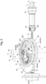
Fig. 2 is a partial perspective view of the shaking device ofFig. 1 wherein a case is omitted. -
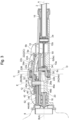
Fig. 3 is a partial cross-sectional bottom view of the shaking device ofFig. 1 . -
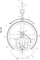
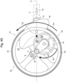
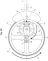
Fig. 4A is a partial front view of a crankshaft unit of the shaking device ofFig. 1 when a connecting rod is in a forward position (beveled gear: 0°). -
Fig. 4B is a partial front view of the crankshaft unit of the shaking device ofFig. 1 when the connecting rod is in an intermediate position (beveled gear: 45°). -
Fig. 4C is a partial front view of the crankshaft unit of the shaking device ofFig. 1 when the connecting rod is in an intermediate position (beveled gear: 90°). -
Fig. 4D is a partial front view of the crankshaft unit of the shaking device ofFig. 1 when the connecting rod is in an intermediate position (beveled gear: 135°). -
Fig. 4E is a partial front view of the crankshaft unit of the shaking device ofFig. 1 when the connecting rod is in a backward position (beveled gear: 180°). - Referring to the drawings, a shaking device according to an exemplary embodiment of the present invention will be described.
- As shown in
Fig. 1 , a shaking device 1 includes apole 2, acase 6 that houses a proximal end of thepole 2, and anengine 8 attached to thecase 6. Thepole 2 has a contactingpart 4, such as a hook or a pusher at aforward end 2b of thepole 2 and is linearly reciprocated along a reciprocating axis A with respect to thecase 6. The contactingpart 4 is configured to engage a branch, such as an olive branch, for shaking it to drop, for example, olives. Thecase 6 has a two-split structure flattened as a whole, including afirst sidewall 6a (Fig. 3 ) disposed on a first side (i.e., a back side not visible inFig. 1 ) of the reciprocating axis A and asecond sidewall 6b disposed on a second side (i.e., a front side visible inFig. 1 ) of the reciprocating axis A opposite to the first side. - As shown in
Fig. 2 andFig. 3 , the shaking device 1 also includes adriving shaft 18 which is driven by theengine 8 and has a beveled pinion (hereinafter this may be simply referred to as a pinion) 20, acrankshaft unit 12 driven by thepinion 20, and a connectingrod 10. Thepole 2 is driven by thepinion 20 via thecrankshaft unit 12 and the connectingrod 10. The drivingshaft 18, thecrankshaft unit 12, and the connectingrod 10 are housed in thecase 6. The drivingshaft 18 extends along a driving axis B which is preferably aligned with the reciprocating axis A. - Referring to
Fig. 3 , theengine 8 is preferably an internal combustion engine, but it may be an electrical or pneumatic engine. The drivingshaft 18 is connected to an output shaft (not shown) of theengine 8 via, for example, a centrifugal clutch (not shown). Thus, the drivingshaft 18 is configured to be rotated by theengine 8 around the driving axis B. - As shown in
Fig. 2 andFig. 3 , thecrankshaft unit 12 includes acrankshaft portion 50 engaging the connectingrod 10, and a reverse-rotation portion 52 described later. Thecrankshaft portion 50 includes abeveled gear 22 as a normal-rotation gear (normal-rotation member) driven by thepinion 20, afirst crankshaft 24, and asecond crankshaft 26. - The
beveled gear 22 is configured to mesh with thepinion 20 at the end of the drivingshaft 18 that transfers the rotation of theengine 8 and decelerate the rotation of the drivingshaft 18. Thebeveled gear 22 is configured to be driven by thepinion 20 to rotate (spin) around the rotation axis C in a first or normal rotational direction R1 (seeFig. 4A to Fig. 4E ). Thebeveled gear 22 includes afirst aperture 22a into which the first crankshaft 24 (or afirst crankpin 24a thereof) is press-fitted from a side of thebeveled gear 22 facing the reciprocating axis A of thepole 2, asecond aperture 22b into which the second crankshaft 26 (or asecond crankpin 26a thereof) is press-fitted from a side of thebeveled gear 22 opposite to the side facing the reciprocating axis A of thepole 2, and a plurality ofholes 22c (four holes in a substantially fan-shape in the illustrated example) arranged in a peripheral direction. Thefirst aperture 22a and thesecond aperture 22b are offset from the rotation axis C and disposed on the opposite sides with respect to the rotation axis C. That is, the phase of the first crankshaft 24 (or thefirst crankpin 24a thereof) press-fitted into thefirst aperture 22a and the phase of the second crankshaft 26 (or thesecond crankpin 26a thereof) press-fitted into thesecond aperture 22b are displaced by 180°. In other words, thebeveled gear 22 includes anannular ring portion 22C, in which a gear meshing with thepinion 20 is formed on the side of thebeveled gear 22 facing the reciprocating axis A of thepole 2, and afirst bridge portion 22A and asecond bridge portion 22B, which cross each other at the center (on the rotation axis C) of thebeveled gear 22. One of thefirst bridge portion 22A or thesecond bridge portion 22B (thefirst bridge portion 22A in the illustrated example) has thefirst aperture 22a and thesecond aperture 22b (on the opposite sides) with the rotation axis C interposed therebetween, which are offset from the rotation axis C. The (four) spaces between thefirst bridge portion 22A and thesecond bridge portion 22B form the substantially fan-shapedholes 22c. - The
beveled gear 22 is disposed (housed) in a space sealed by thefirst sidewall 6a and thesecond sidewall 6b. Thefirst crankpin 24a of thefirst crankshaft 24 press-fitted into thefirst aperture 22a extends from the beveled gear 22 (or thefirst aperture 22a thereof) toward thefirst sidewall 6a along an offset axis D (which is in parallel with and offset from the rotation axis C). The firstmain shaft 24b of thefirst crankshaft 24 extends from thefirst crankpin 24a toward thefirst sidewall 6a along the rotation axis C, and is rotatably supported around the rotation axis C by afirst bearing 30 attached to thefirst sidewall 6a (arecess 6c thereof). Thesecond crankpin 26a of thesecond crankshaft 26 press-fitted into thesecond aperture 22b extends from the beveled gear 22 (or thesecond aperture 22b thereof) toward thesecond sidewall 6b along an offset axis E (which is in parallel with and offset from the rotation axis C). The secondmain shaft 26b of thesecond crankshaft 26 extends from thesecond crankpin 26a toward thesecond sidewall 6b along the rotation axis C, and is rotatably supported around the rotation axis C by asecond bearing 32 attached to thesecond sidewall 6b (arecess 6d thereof). Thus, thecrankshaft portion 50 is configured to be rotated around the rotation axis C in the rotational direction R1. - As shown in
Fig. 3 , the connectingrod 10 has abackward end 10a pivotally attached to thefirst crankpin 24a of thefirst crankshaft 24 via afirst needle bearing 34, and aforward end 10b pivotally attached to abackward end 2a of thepole 2. Thepole 2 is configured to be guided by apole guide 16 fixed to thecase 6 to linearly move thepole 2 along the reciprocating axis A. Thepole 2 is configured to be reciprocated between a most-extended or forward position shown inFig. 4A and a most-retracted or backward position shown inFig. 4E . - As shown in
Fig. 2 andFig. 3 , the reverse-rotation portion 52 of thecrankshaft unit 12 includes a reverse-rotation gear (this may be simply referred to as a gear) 42, and acounterweight 44 attached to thegear 42. Thecounterweight 44 is disposed adjacent to the beveled gear 22 (a face of thebeveled gear 22 opposite to the side facing the reciprocating axis A). Thecounterweight 44 is flattened and includes anattachment portion 46 and aweight portion 48 in, for example, a fan-shape. Theattachment portion 46 of thecounterweight 44 has anaperture 46a into which thesecond crankpin 26a of thesecond crankshaft 26 is rotatably inserted via thesecond needle bearing 36. In other words, thecounterweight 44 includes theattachment portion 46 pivotally attached to thesecond crankpin 26a of thesecond crankshaft 26 via thesecond needle bearing 36, and theweight portion 48 integrally formed with theattachment portion 46. - The
gear 42 has acentral aperture 42a, into which atubular portion 46b of theattachment portion 46 of thecounterweight 44 is inserted, thetubular portion 46b projecting from the face of theaperture 46a of theattachment portion 46 of thecounterweight 44 opposite to the side facing the reciprocating axis A. Thegear 42 is attached to the counterweight 44 (a face of thecounterweight 44 opposite to the side facing the reciprocating axis A) by twobolts 43 so as to be integrally operable. Note that the method of fixing thegear 42 and thecounterweight 44 is not limited to fixing by bolts. In addition, thegear 42 and thecounterweight 44 may be integrally formed. Thegear 42 is configured to mesh with aninternal gear 49 fixed to the case 6 (or astep portion 6e thereof). In the illustrated example, the diameter of theinternal gear 49 is set substantially equal to that of thebeveled gear 22. - Thus, when the
crankshaft portion 50 is driven by thepinion 20 to rotate around the rotation axis C in the rotational direction R1, the reverse-rotation portion 52 is configured to be rotated (revolve) around the rotation axis C in a first or normal rotational direction R1 together (collectively) with thecrankshaft portion 50, and to be rotated (spin) around the offset axis (rotation axis) E in a second or reverse rotational direction R2 (opposite to the first or normal rotational direction R1) by the mesh between thegear 42 and theinternal gear 49. - In the present embodiment, as described above, the phase of the first crankshaft 24 (or the
first crankpin 24a thereof) and the phase of the second crankshaft 26 (or thesecond crankpin 26a thereof) are displaced by 180° around the rotation axis C. In other words, a connection axis (offset axis D) between thebeveled gear 22 and the connectingrod 10 and the offset axis (rotation axis) E are provided on the opposite sides with respect to the rotation axis C (the phases are displaced by 180°). The position of the center of gravity of the reverse-rotation portion 52 including thecounterweight 44 and thegear 42 is adjusted to be on the reference pitch circle of the gear 42 (seeFig. 4A to Fig. 4E ). The reference pitch circle diameter (the number of teeth) of thegear 42 is set to half of the reference pitch circle diameter (the number of teeth) of theinternal gear 49. - Thus, when the
pole 2 is in the forward position, the center of gravity of the reverse-rotation portion 52 including thecounterweight 44 and thegear 42 is positioned in a backward position (on the reciprocating axis A) as shown inFig. 4A , whereas when thepole 2 is in the backward position, the center of gravity of the reverse-rotation portion 52 including thecounterweight 44 and thegear 42 is positioned in a forward position (on the reciprocating axis A) as shown inFig. 4E . In this manner, the center of gravity of the reverse-rotation portion 52 is positioned contrary to the movement of thepole 2, so that the vibrations caused in the forward and backward directions and transferred to the operator are mitigated. In addition, as shown inFig. 4A to Fig. 4E , when thepole 2 is in an intermediate position on the way from the forward position to the backward position, the center of gravity of the reverse-rotation portion 52 moves in a direction opposite to the moving direction of thepole 2 on the same reciprocating axis A as thepole 2 being the reciprocating portion. In addition, the center of gravity of the reverse-rotation portion 52 is disposed to linearly reciprocate on the reciprocating axis A as a whole. Thecounterweight 44 having such a configuration will not cause the perpendicular centrifugal force produced by rotation as in the conventional counterweight. - In addition, the reverse-
rotation portion 52 can be configured using only asingle counterweight 44. This is because while the rotating counterweight as in the conventional structure requires a counterrotating counterweight to counteract the centrifugal force of the rotating counterweight, thecounterweight 44 of the present embodiment does not cause a centrifugal force. Thus, it is possible to reduce the thickness of thecase 6 in a direction along the rotation axis C. In addition, since thecounterweight 44 of the reverse-rotation portion 52 is disposed nearer to the reciprocating axis A (in the direction along the rotation axis C) than thegear 42 and the distance between the reciprocating axis A and thecounterweight 44 is small, it is possible to significantly reduce the twisting force caused by thecounterweight 44 with respect to the reciprocating axis A as compared to the conventional configuration of rotating the counterweight around the flywheel shaft. - Referring to
Fig. 4A to Fig. 4E , an operation of the shaking device 1 will be described. - The driving
shaft 18 is rotated by theengine 8 via the output shaft (not shown) of theengine 8 and the centrifugal clutch (nor shown). Thebeveled gear 22 is rotated by thepinion 20 around the rotation axis C in the first rotational direction R1. The direction of the rotation axis C is a left-to-right direction when the direction in which an operator usually faces a working part is set as the front. - The
first crankshaft 24 is rotated together with thebeveled gear 22 so that thepole 2 is linearly reciprocated along the reciprocating axis A via the connectingrod 10. The reciprocating action of thepole 2 allows the contactingpart 4 vibrating in the direction along the reciprocating axis A to drop, for example, olives. - The
second crankshaft 26 is rotated together with thebeveled gear 22, and the reverse-rotation portion 52 is rotated (revolves) together with thebeveled gear 22 around the rotation axis C in the first rotational direction R1. Meanwhile, since thegear 42 of the reverse-rotation portion 52 meshes with theinternal gear 49 fixed to thecase 6, the reverse-rotation portion 52 is rotated (spins) around the offset axis (rotation axis) E in the second rotational direction R2 opposite to the first rotational direction R1. - As shown in
Fig. 4A , when thepole 2 moves toward the forward position, a shock (inertial force Fp) in a direction from a backward side toward a forward side is generated. However, since the center of gravity G of the reverse-rotation portion 52 simultaneously reaches the backward position, and the inertial force Fg in a direction from a forward side toward a backward side is generated in the reverse-rotation portion 52, the above-described shock transferred to the operator can be reduced. - As shown in
Fig. 4B ,Fig. 4C ,Fig. 4D , when thepole 2 reaches the intermediate position while it moves from the forward position to the backward position, as described above, the reverse-rotation portion 52 performs two types of rotational motion, i.e., revolution around the rotation axis C in the first rotational direction R1 and spinning around the offset axis (rotation axis) E in the second rotational direction R2, whereby the center of gravity G of the reverse-rotation portion 52 is reciprocated opposite to the pole 2 (reciprocating portion) on the same reciprocating axis A as the pole 2 (reciprocating portion), and does not accompany upward and downward components. As a result, a force (shock) in a direction perpendicular to the reciprocating axis A (upward and downward directions with respect to the operator) will not be generated. - As shown in
Fig. 4E , when thepole 2 moves toward the backward position, a shock (inertial force Fp) in a direction from a forward side toward a backward side is generated. However, since the center of gravity G of the reverse-rotation portion 52 simultaneously reaches the forward position, and the inertial force Fg in a direction from a backward side toward a forward side is generated in the reverse-rotation portion 52, the above-described shock transferred to the operator can be reduced. - Similarly, though not shown in the drawings, when the
pole 2 reaches the intermediate position while it moves from the backward position to the forward position, the center of gravity G of the reverse-rotation portion 52 is reciprocated opposite to the pole 2 (reciprocating portion) on the same reciprocating axis A as the pole 2 (reciprocating portion), and does not accompany upward and downward components. As a result, a force (shock) in a direction perpendicular to the reciprocating axis A (upward and downward directions with respect to the operator) will not be generated. - As described above, the shaking device 1 of the present embodiment includes a
crankshaft unit 12 driven by a driving source (engine 8); a connectingrod 10; and a reciprocating portion (pole 2) having a contactingpart 4, the reciprocating portion (pole 2) being reciprocated between a forward position and a backward position along a reciprocating axis A by thecrankshaft unit 12 via the connectingrod 10. Thecrankshaft unit 12 includes acrankshaft portion 50 engaging the connectingrod 10, and a reverse-rotation portion 52. Thecrankshaft portion 50 includes a normal-rotation member (beveled gear 22) driven by the driving source (engine 8) to rotate (spin) around a first rotation axis C in a first rotational direction R1. The reverse-rotation portion 52 includes a reverse-rotation gear 42 having acounterweight 44 attached thereto, the reverse-rotation gear 42 being configured to mesh with aninternal gear 49 fixed to acase 6 and to be driven so as to revolve around the first rotation axis C in the first rotational direction R1 together (collectively) with the normal-rotation member (beveled gear 22) and spin around a second rotation axis E offset (in parallel) from the first rotation axis C in a second rotational direction R2 opposite to the first rotational direction R1. Thecounterweight 44 and the reverse-rotation gear 42 perform (two types of) rotational motion, revolution around the first rotation axis C and spinning around the second rotation axis E, whereby a center of gravity of the reverse-rotation portion 52 including thecounterweight 44 and the reverse-rotation gear 42 is reciprocated along the same reciprocating axis A as the reciprocating portion (pole 2). - In addition, a reference pitch circle diameter (the number of teeth) of the reverse-
rotation gear 42 is set to half of a reference pitch circle diameter (the number of teeth) of theinternal gear 49. According to this configuration, since the reverse-rotation gear 42 makes one rotation during a half rotation of thebeveled gear 22, it is possible to direct thecounterweight 44 outward at a timing when the reverse-rotation gear 42 reaches a forward position and a backward position, thus making full use of the inertial force acting on thecounterweight 44. - In addition, preferably, a position of a center of gravity of the reverse-
rotation portion 52 including thecounterweight 44 and the reverse-rotation gear 42 is disposed on a reference pitch circle of the reverse-rotation gear 42. According to this configuration, it is possible to match the position of the center of gravity of the reverse-rotation portion 52 during reciprocating with the reciprocating axis A, thus minimizing the component of the vertical vibrations. However, even if the component of the vertical vibrations is generated due to displacement of the center of gravity of the reverse-rotation portion 52 during reciprocating from the position on the reciprocating axis A, a force perpendicular to the reciprocating axis A can be reduced since the stroke perpendicular to the reciprocating axis A is sufficiently smaller than the stroke in the direction along the reciprocating axis A, as compared to the conventional configuration of rotating the counterweight around the flywheel shaft. - In addition, preferably, a connection axis between the normal-rotation member (beveled gear 22) and the connecting
rod 10 and the second rotation axis E are provided on opposite sides with respect to the first rotation axis C. According to this configuration, the reciprocating portion (pole 2) and thecounterweight 44 move toward the opposite directions, and thus it is possible to counteract the inertial force acting on the reciprocating portion (pole 2) by the inertial force of thecounterweight 44. In addition, by disposing thefirst crankpin 24a and thesecond crankpin 26a on the opposite sides with respect to the rotation axis C, the position of the center of gravity of thecrankshaft unit 12 comes closer to the rotation axis C, and it is possible to reduce an excess centrifugal force caused around the rotation axis C during operation. - In addition, preferably, the
counterweight 44 is disposed nearer to the reciprocating axis A (or the beveled gear 22) than the reverse-rotation gear 42. According to this configuration, the position of the center of gravity of the reverse-rotation portion 52 comes closer to the reciprocating axis A of the reciprocating portion (pole 2), and thus it is possible to reduce the twisting force caused by thecounterweight 44 with respect to the reciprocating axis A. - In addition, when the reciprocating portion (pole 2) is in the forward position, a center of gravity of the reverse-
rotation portion 52 including thecounterweight 44 and the reverse-rotation gear 42 is positioned in a backward position, and when the reciprocating portion (pole 2) is in the backward position, a center of gravity of the reverse-rotation portion 52 including thecounterweight 44 and the reverse-rotation gear 42 is positioned in a forward position. When the reciprocating portion (pole 2) moves between the forward position and the backward position, the center of gravity of the reverse-rotation portion 52 moves along the reciprocating axis A between the backward position and the forward position in a direction opposite to the moving direction of the reciprocating portion (pole 2). - According to the present embodiment, since a center of gravity of the reverse-
rotation portion 52 including thecounterweight 44 and the reverse-rotation gear 42 is reciprocated (linearly moved) along the same reciprocating axis A as the reciprocating portion (pole 2), not making its center of gravity rotated, it is possible to provide an improved compact and lightweight shaking device 1 having fewer components and a simple structure, capable of counteracting the inertial force acting on the reciprocating portion without causing vibrations in a direction perpendicular to the inertial force of the reciprocating portion. - It should be noted that although the
engine 8 is used as a driving source in the above-described embodiment, a motor may be used. In addition, although thebeveled gear 22 is rotated and driven by thepinion 20 around the rotation axis C in the first rotational direction R1 in the above-described embodiment, for a normal-rotation member rotating around the rotation axis C in the first rotational direction R1, any member other than thebeveled gear 22 may be used. For example, instead of rotating the drivingshaft 18, the normal-rotation member may be rotated by a structure in which a motor is coupled to the firstmain shaft 24b of thefirst crankshaft 24 or the secondmain shaft 26b of thesecond crankshaft 26. - Although the exemplary embodiment of the present invention has been described above, the present invention is not limited to the above embodiment, and can be changed appropriately without departing from the spirit of the present invention.
-
- 1
- Shaking device
- 2
- Pole (reciprocating portion)
- 2a
- Backward end
- 2b
- Forward end
- 4
- Contacting part
- 6
- Case
- 6a
- First sidewall
- 6b
- Second sidewall
- 8
- Engine (driving source)
- 10
- Connecting rod
- 10a
- Backward end
- 10b
- Forward end
- 12
- Crankshaft unit
- 16
- Pole guide
- 18
- Driving shaft
- 20
- Beveled pinion
- 22
- Beveled gear (normal-rotation member)
- 22a
- First aperture
- 22b
- Second aperture
- 22c
- Hole
- 22A
- First bridge portion
- 22B
- Second bridge portion
- 22C
- Annular ring portion
- 24
- First crankshaft
- 24a
- First crankpin
- 24b
- First main shaft
- 26
- Second crankshaft
- 26a
- Second crankpin
- 26b
- Second main shaft
- 30
- First bearing
- 32
- Second bearing
- 34
- First needle bearing
- 36
- Second needle bearing
- 42
- Reverse-rotation gear
- 42a
- Central aperture
- 43
- Bolt
- 44
- Counterweight
- 46
- Attachment portion
- 46a
- Aperture
- 46b
- Tubular portion
- 48
- Weight portion
- 49
- Internal gear
- 50
- Crankshaft portion
- 52
- Reverse-rotation portion
- A
- Reciprocating axis
- B
- Driving axis
- C
- Rotation axis (first rotation axis)
- D
- Offset axis
- E
- Offset axis (second rotation axis)
- R1
- First rotational direction
- R2
- Second rotational direction
Claims (6)
- A shaking device (1), comprising:a crankshaft unit (12) driven by a driving source (8);a connecting rod (10); anda reciprocating portion (2) having a contacting part (4), the reciprocating portion (2) being reciprocated between a forward position and a backward position along a reciprocating axis (A) by the crankshaft unit (12) via the connecting rod (10),wherein the crankshaft unit (12) includes a crankshaft portion (50) engaging the connecting rod (10), and a reverse-rotation portion (52);wherein the crankshaft portion (50) includes a normal-rotation member (22) driven by the driving source (8) to rotate around a first rotation axis (C) in a first rotational direction (Rl);wherein the reverse-rotation portion (52) includes a reverse-rotation gear (42) having a counterweight (44) attached thereto, the reverse-rotation gear (42) being configured to mesh with an internal gear (49) fixed to a case (6) and to be driven so as to revolve around the first rotation axis (C) in the first rotational direction (R1) together with the normal-rotation member (22) and spin around a second rotation axis (E) offset from the first rotation axis (C) in a second rotational direction (R2) opposite to the first rotational direction (R1); andwherein the counterweight (44) and the reverse-rotation gear (42) perform rotational motion, revolution around the first rotation axis (C) and spinning around the second rotation axis (E), whereby a center of gravity of the reverse-rotation portion (52) including the counterweight (44) and the reverse-rotation gear (42) is reciprocated along the same reciprocating axis (A) as the reciprocating portion (2).
- The shaking device (1) according to claim 1, wherein a reference pitch circle diameter of the reverse-rotation gear (42) is set to half of a reference pitch circle diameter of the internal gear (49).
- The shaking device (1) according to claim 1 or 2, wherein a position of a center of gravity of the reverse-rotation portion (52) including the counterweight (44) and the reverse-rotation gear (42) is disposed on a reference pitch circle of the reverse-rotation gear (42).
- The shaking device (1) according to claim 1 or 2, wherein a connection axis between the normal-rotation member (22) and the connecting rod (10) and the second rotation axis (E) are provided on opposite sides with respect to the first rotation axis (C).
- The shaking device (1) according to claim 1 or 2, wherein the counterweight (44) is disposed nearer to the reciprocating axis (A) than the reverse-rotation gear (42).
- The shaking device (1) according to claim 1 or 2, wherein when the reciprocating portion (2) is in the forward position, a center of gravity of the reverse-rotation portion (52) including the counterweight (44) and the reverse-rotation gear (42) is positioned in a backward position, and when the reciprocating portion (2) is in the backward position, a center of gravity of the reverse-rotation portion (52) including the counterweight (44) and the reverse-rotation gear (42) is positioned in a forward position.
Applications Claiming Priority (1)
| Application Number | Priority Date | Filing Date | Title |
|---|---|---|---|
| JP2022155290A JP7787793B2 (en) | 2022-09-28 | 2022-09-28 | Shake-off device |
Publications (2)
| Publication Number | Publication Date |
|---|---|
| EP4344533A1 true EP4344533A1 (en) | 2024-04-03 |
| EP4344533B1 EP4344533B1 (en) | 2026-02-25 |
Family
ID=88192123
Family Applications (1)
| Application Number | Title | Priority Date | Filing Date |
|---|---|---|---|
| EP23199250.4A Active EP4344533B1 (en) | 2022-09-28 | 2023-09-22 | Shaking device |
Country Status (3)
| Country | Link |
|---|---|
| EP (1) | EP4344533B1 (en) |
| JP (1) | JP7787793B2 (en) |
| ES (1) | ES3064769T3 (en) |
Citations (7)
| Publication number | Priority date | Publication date | Assignee | Title |
|---|---|---|---|---|
| EP1627561B1 (en) * | 2003-04-25 | 2007-11-21 | Gurri Molins, José | Force-balancing or -multiplying device which is intended for a portable mechanical beater/collector |
| EP2042020A1 (en) | 2007-09-27 | 2009-04-01 | Andreas Stihl AG & Co. KG | Portable, hand-operated harvesting device |
| EP1598571B1 (en) * | 2004-05-18 | 2010-04-28 | Cifarelli S.p.A. | Portable apparatus for shaking fruit trees, particularly olive trees |
| EP2625948A1 (en) | 2012-02-09 | 2013-08-14 | Tekna S.R.L | Shaking device |
| CN103460904A (en) * | 2013-09-29 | 2013-12-25 | 东北农业大学 | Multi-direction vibrating portable small berry picker |
| DE102021129345A1 (en) * | 2020-11-17 | 2022-05-19 | Cifarelli S.P.A. | PORTABLE AGRICULTURAL MACHINE WITH AXIAL/LINEAR MOTOR |
| WO2022172315A1 (en) * | 2021-02-09 | 2022-08-18 | カワサキモータース株式会社 | Power device, and propulsion device for movement |
Family Cites Families (2)
| Publication number | Priority date | Publication date | Assignee | Title |
|---|---|---|---|---|
| JP3742150B2 (en) * | 1996-07-30 | 2006-02-01 | 株式会社ニッカリ | Vibrating fruit harvester |
| JP2002186333A (en) | 2000-12-21 | 2002-07-02 | Kioritz Corp | Tree remover |
-
2022
- 2022-09-28 JP JP2022155290A patent/JP7787793B2/en active Active
-
2023
- 2023-09-22 ES ES23199250T patent/ES3064769T3/en active Active
- 2023-09-22 EP EP23199250.4A patent/EP4344533B1/en active Active
Patent Citations (7)
| Publication number | Priority date | Publication date | Assignee | Title |
|---|---|---|---|---|
| EP1627561B1 (en) * | 2003-04-25 | 2007-11-21 | Gurri Molins, José | Force-balancing or -multiplying device which is intended for a portable mechanical beater/collector |
| EP1598571B1 (en) * | 2004-05-18 | 2010-04-28 | Cifarelli S.p.A. | Portable apparatus for shaking fruit trees, particularly olive trees |
| EP2042020A1 (en) | 2007-09-27 | 2009-04-01 | Andreas Stihl AG & Co. KG | Portable, hand-operated harvesting device |
| EP2625948A1 (en) | 2012-02-09 | 2013-08-14 | Tekna S.R.L | Shaking device |
| CN103460904A (en) * | 2013-09-29 | 2013-12-25 | 东北农业大学 | Multi-direction vibrating portable small berry picker |
| DE102021129345A1 (en) * | 2020-11-17 | 2022-05-19 | Cifarelli S.P.A. | PORTABLE AGRICULTURAL MACHINE WITH AXIAL/LINEAR MOTOR |
| WO2022172315A1 (en) * | 2021-02-09 | 2022-08-18 | カワサキモータース株式会社 | Power device, and propulsion device for movement |
Also Published As
| Publication number | Publication date |
|---|---|
| ES3064769T3 (en) | 2026-04-28 |
| JP2024049055A (en) | 2024-04-09 |
| EP4344533B1 (en) | 2026-02-25 |
| JP7787793B2 (en) | 2025-12-17 |
Similar Documents
| Publication | Publication Date | Title |
|---|---|---|
| JP4959896B2 (en) | Inner cycloid engine | |
| EP1983215A1 (en) | Reciprocating piston machine and internal combustion engine | |
| JPH04157238A (en) | Balancer for engine | |
| KR102000822B1 (en) | Energy-saving equilibrium mechanism, rotating machine and method of implementation | |
| WO2009018863A1 (en) | A reciprocating piston mechanism | |
| CN113272539A (en) | Piston type internal combustion engine with generator | |
| EP4344533B1 (en) | Shaking device | |
| WO2022112275A1 (en) | An internal combustion engine including variable compression ratio | |
| JP2009281458A (en) | Internal combustion engine equipped with balancer device | |
| US20100031916A1 (en) | Hypocycloid Engine | |
| JP2020026803A (en) | Gear unit and assembling method thereof | |
| JP2003510528A (en) | Conversion from linear reciprocating motion to rotary motion | |
| JP5103653B2 (en) | Vibration removal device for reciprocating machine | |
| JP6218599B2 (en) | Output extraction device for automobile engine | |
| JP6398172B2 (en) | Internal combustion engine | |
| JP2024542216A (en) | Eccentric member and internal combustion engine | |
| JP2011069301A (en) | Internal combustion engine | |
| JP5328918B2 (en) | 2-cylinder engine | |
| EP4159025B1 (en) | Shaking device | |
| CN115182966B (en) | A new type of internal combustion engine balance structure and internal combustion engine | |
| EP4006323B1 (en) | An internal combustion engine including variable compression ratio | |
| CN107869388B (en) | Engine | |
| JPH11117997A (en) | Balance shaft device | |
| EP0245583A2 (en) | Inline counterbalance weight system for a single cylinder engine | |
| JP5552198B1 (en) | Internal combustion engine |
Legal Events
| Date | Code | Title | Description |
|---|---|---|---|
| PUAI | Public reference made under article 153(3) epc to a published international application that has entered the european phase |
Free format text: ORIGINAL CODE: 0009012 |
|
| STAA | Information on the status of an ep patent application or granted ep patent |
Free format text: STATUS: THE APPLICATION HAS BEEN PUBLISHED |
|
| AK | Designated contracting states |
Kind code of ref document: A1 Designated state(s): AL AT BE BG CH CY CZ DE DK EE ES FI FR GB GR HR HU IE IS IT LI LT LU LV MC ME MK MT NL NO PL PT RO RS SE SI SK SM TR |
|
| STAA | Information on the status of an ep patent application or granted ep patent |
Free format text: STATUS: REQUEST FOR EXAMINATION WAS MADE |
|
| 17P | Request for examination filed |
Effective date: 20240823 |
|
| RBV | Designated contracting states (corrected) |
Designated state(s): AL AT BE BG CH CY CZ DE DK EE ES FI FR GB GR HR HU IE IS IT LI LT LU LV MC ME MK MT NL NO PL PT RO RS SE SI SK SM TR |
|
| RIC1 | Information provided on ipc code assigned before grant |
Ipc: A01D 46/26 20060101AFI20250824BHEP |
|
| GRAP | Despatch of communication of intention to grant a patent |
Free format text: ORIGINAL CODE: EPIDOSNIGR1 |
|
| STAA | Information on the status of an ep patent application or granted ep patent |
Free format text: STATUS: GRANT OF PATENT IS INTENDED |
|
| INTG | Intention to grant announced |
Effective date: 20251013 |
|
| GRAS | Grant fee paid |
Free format text: ORIGINAL CODE: EPIDOSNIGR3 |
|
| GRAA | (expected) grant |
Free format text: ORIGINAL CODE: 0009210 |
|
| STAA | Information on the status of an ep patent application or granted ep patent |
Free format text: STATUS: THE PATENT HAS BEEN GRANTED |
|
| AK | Designated contracting states |
Kind code of ref document: B1 Designated state(s): AL AT BE BG CH CY CZ DE DK EE ES FI FR GB GR HR HU IE IS IT LI LT LU LV MC ME MK MT NL NO PL PT RO RS SE SI SK SM TR |
|
| RAP3 | Party data changed (applicant data changed or rights of an application transferred) |
Owner name: YAMABIKO CORPORATION |
|
| REG | Reference to a national code |
Ref country code: CH Ref legal event code: F10 Free format text: ST27 STATUS EVENT CODE: U-0-0-F10-F00 (AS PROVIDED BY THE NATIONAL OFFICE) Effective date: 20260225 Ref country code: GB Ref legal event code: FG4D |
|
| REG | Reference to a national code |
Ref country code: DE Ref legal event code: R096 Ref document number: 602023012531 Country of ref document: DE |
|
| REG | Reference to a national code |
Ref country code: IE Ref legal event code: FG4D |
|
| REG | Reference to a national code |
Ref country code: ES Ref legal event code: FG2A Ref document number: 3064769 Country of ref document: ES Kind code of ref document: T3 Effective date: 20260428 |
|
| REG | Reference to a national code |
Ref country code: NL Ref legal event code: MP Effective date: 20260225 |
|
| PG25 | Lapsed in a contracting state [announced via postgrant information from national office to epo] |
Ref country code: RS Free format text: LAPSE BECAUSE OF FAILURE TO SUBMIT A TRANSLATION OF THE DESCRIPTION OR TO PAY THE FEE WITHIN THE PRESCRIBED TIME-LIMIT Effective date: 20260525 |
|
| PG25 | Lapsed in a contracting state [announced via postgrant information from national office to epo] |
Ref country code: PL Free format text: LAPSE BECAUSE OF FAILURE TO SUBMIT A TRANSLATION OF THE DESCRIPTION OR TO PAY THE FEE WITHIN THE PRESCRIBED TIME-LIMIT Effective date: 20260225 |
|
| PG25 | Lapsed in a contracting state [announced via postgrant information from national office to epo] |
Ref country code: GR Free format text: LAPSE BECAUSE OF FAILURE TO SUBMIT A TRANSLATION OF THE DESCRIPTION OR TO PAY THE FEE WITHIN THE PRESCRIBED TIME-LIMIT Effective date: 20260526 |
|
| REG | Reference to a national code |
Ref country code: LT Ref legal event code: MG9D |
|
| PG25 | Lapsed in a contracting state [announced via postgrant information from national office to epo] |
Ref country code: LT Free format text: LAPSE BECAUSE OF FAILURE TO SUBMIT A TRANSLATION OF THE DESCRIPTION OR TO PAY THE FEE WITHIN THE PRESCRIBED TIME-LIMIT Effective date: 20260225 |
|
| PG25 | Lapsed in a contracting state [announced via postgrant information from national office to epo] |
Ref country code: NO Free format text: LAPSE BECAUSE OF FAILURE TO SUBMIT A TRANSLATION OF THE DESCRIPTION OR TO PAY THE FEE WITHIN THE PRESCRIBED TIME-LIMIT Effective date: 20260525 |
|
| PG25 | Lapsed in a contracting state [announced via postgrant information from national office to epo] |
Ref country code: SE Free format text: LAPSE BECAUSE OF FAILURE TO SUBMIT A TRANSLATION OF THE DESCRIPTION OR TO PAY THE FEE WITHIN THE PRESCRIBED TIME-LIMIT Effective date: 20260225 Ref country code: AT Free format text: LAPSE BECAUSE OF FAILURE TO SUBMIT A TRANSLATION OF THE DESCRIPTION OR TO PAY THE FEE WITHIN THE PRESCRIBED TIME-LIMIT Effective date: 20260225 Ref country code: FI Free format text: LAPSE BECAUSE OF FAILURE TO SUBMIT A TRANSLATION OF THE DESCRIPTION OR TO PAY THE FEE WITHIN THE PRESCRIBED TIME-LIMIT Effective date: 20260225 |
|
| REG | Reference to a national code |
Ref country code: AT Ref legal event code: MK05 Ref document number: 1889720 Country of ref document: AT Kind code of ref document: T Effective date: 20260225 |
|
| PG25 | Lapsed in a contracting state [announced via postgrant information from national office to epo] |
Ref country code: HR Free format text: LAPSE BECAUSE OF FAILURE TO SUBMIT A TRANSLATION OF THE DESCRIPTION OR TO PAY THE FEE WITHIN THE PRESCRIBED TIME-LIMIT Effective date: 20260225 |
|
| PG25 | Lapsed in a contracting state [announced via postgrant information from national office to epo] |
Ref country code: PT Free format text: LAPSE BECAUSE OF FAILURE TO SUBMIT A TRANSLATION OF THE DESCRIPTION OR TO PAY THE FEE WITHIN THE PRESCRIBED TIME-LIMIT Effective date: 20260625 Ref country code: IS Free format text: LAPSE BECAUSE OF FAILURE TO SUBMIT A TRANSLATION OF THE DESCRIPTION OR TO PAY THE FEE WITHIN THE PRESCRIBED TIME-LIMIT Effective date: 20260625 |
|
| PG25 | Lapsed in a contracting state [announced via postgrant information from national office to epo] |
Ref country code: NL Free format text: LAPSE BECAUSE OF FAILURE TO SUBMIT A TRANSLATION OF THE DESCRIPTION OR TO PAY THE FEE WITHIN THE PRESCRIBED TIME-LIMIT Effective date: 20260225 |
|
| PG25 | Lapsed in a contracting state [announced via postgrant information from national office to epo] |
Ref country code: LV Free format text: LAPSE BECAUSE OF FAILURE TO SUBMIT A TRANSLATION OF THE DESCRIPTION OR TO PAY THE FEE WITHIN THE PRESCRIBED TIME-LIMIT Effective date: 20260225 |
|
| PG25 | Lapsed in a contracting state [announced via postgrant information from national office to epo] |
Ref country code: BG Free format text: LAPSE BECAUSE OF FAILURE TO SUBMIT A TRANSLATION OF THE DESCRIPTION OR TO PAY THE FEE WITHIN THE PRESCRIBED TIME-LIMIT Effective date: 20260225 |