EP4006323B1 - An internal combustion engine including variable compression ratio - Google Patents
An internal combustion engine including variable compression ratio Download PDFInfo
- Publication number
- EP4006323B1 EP4006323B1 EP20210071.5A EP20210071A EP4006323B1 EP 4006323 B1 EP4006323 B1 EP 4006323B1 EP 20210071 A EP20210071 A EP 20210071A EP 4006323 B1 EP4006323 B1 EP 4006323B1
- Authority
- EP
- European Patent Office
- Prior art keywords
- gear
- eccentric member
- balancing
- internal combustion
- combustion engine
- Prior art date
- Legal status (The legal status is an assumption and is not a legal conclusion. Google has not performed a legal analysis and makes no representation as to the accuracy of the status listed.)
- Active
Links
- 238000002485 combustion reaction Methods 0.000 title claims description 34
- 230000006835 compression Effects 0.000 title claims description 13
- 238000007906 compression Methods 0.000 title claims description 13
- 230000005484 gravity Effects 0.000 claims description 59
- 230000033001 locomotion Effects 0.000 description 3
- 230000001010 compromised effect Effects 0.000 description 1
- 230000003247 decreasing effect Effects 0.000 description 1
- 238000005474 detonation Methods 0.000 description 1
- 238000010304 firing Methods 0.000 description 1
Images


Classifications
-
- F—MECHANICAL ENGINEERING; LIGHTING; HEATING; WEAPONS; BLASTING
- F02—COMBUSTION ENGINES; HOT-GAS OR COMBUSTION-PRODUCT ENGINE PLANTS
- F02B—INTERNAL-COMBUSTION PISTON ENGINES; COMBUSTION ENGINES IN GENERAL
- F02B75/00—Other engines
- F02B75/04—Engines with variable distances between pistons at top dead-centre positions and cylinder heads
- F02B75/048—Engines with variable distances between pistons at top dead-centre positions and cylinder heads by means of a variable crank stroke length
Definitions
- the present invention relates to an internal combustion engine including variable compression ratio comprising a crankshaft being rotatable about a crankshaft axis and having a crankpin, wherein the crankshaft axis and a centreline of the crankpin span a crank plane, a connecting rod, a piston being rotatably connected to a distal end portion of the connecting rod, an eccentric member being rotatably mounted on the crankpin and comprising a bearing portion having an outer circumferential wall which bears a proximal end portion of the connecting rod such that the connecting rod is rotatably mounted on the bearing portion, wherein the bearing portion is eccentrically disposed with respect to the crankpin and the eccentric member is provided with an eccentric member gear which is drivably coupled to a gear train for rotating the eccentric member with respect to the crankpin.
- Such an internal combustion engine is known from EP 3 365 544 .
- the gear train comprises a first intermediate gear which meshes with the eccentric member gear and which is fixed to a second intermediate gear that has a smaller diameter than the first intermediate gear.
- the first and second intermediate gears are rotatably mounted to the crankshaft and have a common axis of rotation which extends parallel to the crankshaft axis and a centreline of the crankpin.
- the gear train further comprises an actuating gear which meshes with the second intermediate gear and which is fixed to an actuating shaft that extends through the crankshaft.
- the actuating shaft is rotatable with respect to the crankshaft about the crankshaft axis.
- the actuating shaft In case of running at fixed compression ratio the actuating shaft has a fixed angular position with respect to a crankcase of the engine.
- the gear ratios of the gears of the gear train and the eccentric member gear are such that under operating conditions, in case of a standstill of the actuating gear, the eccentric member is rotated with respect to the crankpin at half speed of the speed of the crankshaft with respect to the crankcase and in opposite direction thereof.
- the eccentric member rotates once about the crankpin in opposite direction; as seen from the crankcase the eccentric member rotates once about the centreline of the crankpin in the same rotational direction as the crankshaft.
- an inertial force on the eccentric member may lead to a torque about the centreline of the crankpin under operating conditions when the direction of such inertial force is angled with respect to a plane that is spanned by the centreline of the crankpin and a centreline of the bearing portion of the eccentric member.
- the location of maximum eccentricity of the eccentric member lies in this plane.
- the torque on the eccentric member is transferred to the gear train and may lead to a relatively high force peak on gear teeth, particularly on gear teeth of the relatively small actuating gear. This drawback typically increases in case of small high-speed engines, which may run at a speed of more than 6000 rpm, for example.
- the present invention aims to improve the internal combustion as described above.
- the internal combustion engine according to the invention is characterized in that the gear train comprises a balancing gear which is rotatably mounted to the crankshaft and rotates with respect to the crankshaft about a balancing gear axis at the same speed as the eccentric member gear under operating conditions, wherein the crankshaft axis and the balancing gear axis span a balancing gear plane, wherein the balancing gear has an eccentrical centre of gravity which is located such that under operating conditions it causes a counter torque against a torque that is exerted by the eccentric member gear onto the balancing gear due to an inertial force on the eccentric member.
- the counter torque is generated by a centrifugal force on the balancing gear which has a direction from the crankshaft axis to the centre of gravity of the balancing gear.
- An advantage of providing a counter torque by the balancing gear is that the torque which is exerted by the eccentric member onto the balancing gear is not or not fully transferred to one or more gears of the gear train which are drivably coupled to the eccentric member gear via the balancing gear.
- the inertial force on the eccentric member may be generated by inertia of at least one of the piston, the connecting rod and the eccentric member itself.
- the inertial force of the piston and the connecting rod onto the eccentric member is high; when in this situation a plane that is spanned by the centreline of the crankpin and a centreline of the bearing portion is angled with respect to the direction of the inertial force, the inertial force generates a torque on the eccentric member about the centreline of the crankpin.
- This torque is transferred to the balancing gear, but due to the invention it is not or not fully transferred further to one or more gears of the gear train which are drivably coupled to the eccentric member gear via the balancing gear.
- the gear train has more than one gear and is adapted such that the balancing gear rotates about the balancing gear axis at the same speed as the eccentric member gear rotates about the crankpin.
- the gear train is adapted such that the eccentric member rotates with respect to the crankpin at half speed of the speed of the crankshaft and in opposite direction thereof, since the relative motion of the eccentric member and the crankpin, on the one hand, and of the eccentric member and the connecting rod, on the other hand, is relatively small, which minimizes friction losses.
- bearings between the bearing portion and the connecting rod and between the eccentric member and the crankpin experience half the crankshaft speed.
- the internal combustion engine may also have a control mechanism which is drivably coupled to the gear train in order to vary the compression ratio of the internal combustion engine.
- the eccentric member has an eccentrical centre of gravity and the inertial force is a centrifugal force caused by the eccentrical centre of gravity of the eccentric member.
- centrifugal forces of the eccentric member and the balancing gear in the centres of gravity of the eccentric member and the balancing gear, respectively, are directed radially from the crankshaft axis; centrifugal forces in the centres of gravity due to rotation of the eccentric member about the crankpin and the balancing gear about the balancing gear axis, respectively, are neglected since their rotational speeds are half of the rotational speed of the crankshaft.
- the centre of gravity of the eccentric member lies in a plane that is spanned by the centreline of the crankpin and a centreline of the bearing portion, wherein the eccentric member and the balancing gear are arranged such that when under operating conditions the centre of gravity of the eccentric member lies in the crank plane, the centre of gravity of the balancing gear lies in the balancing gear plane.
- This synchronizes the torque and counter torque under operating conditions, such that the torque and counter torque increase at the same time and decrease at the same time.
- the centre of gravity of the eccentric member lies in the crank plane and the centre of gravity of the balancing gear lies in the balancing gear plane the torque and counter torque are zero. It is noted that in this case there may still be another inertial force than the centrifugal force onto the eccentric member, which generates a torque on the eccentric member.
- the centre of gravity of the eccentric member lies in the crank plane and the centreline of the crankpin lies between the crankshaft axis and the centre of gravity of the eccentric member, the centre of gravity of the balancing gear lies between the crankshaft axis and the balancing gear axis.
- the eccentric member gear and the balancing gear may rotate in opposite direction with respect to each other under operating conditions.
- the gear train comprises an actuating gear which is drivably coupled to the balancing gear and fixed to an actuating shaft, wherein the actuating shaft is rotatably mounted to the crankshaft and rotatable about an axis which coincides with the crankshaft axis, wherein under operating conditions the actuating shaft stands still at fixed compression ratio.
- the actuating gear may be located at the same side of a crank arm of the crankshaft as the eccentric member gear and the balancing gear, whereas the actuating shaft extends through the crankshaft. It is noted that a stand still of the actuating shaft means that the actuating shaft has a fixed position with respect to a crankcase of the internal combustion engine.
- the balancing gear is a first stage gear that is fixed to a second stage gear and which has a larger diameter than the second stage gear, wherein the second stage gear meshes with the actuating gear.
- the second stage gear also forms part of the gear train.
- crank plane and the balancing gear plane may coincide.
- the balancing gear is an intermediate gear which meshes with the actuating gear.
- the number of teeth of the intermediate gear equals the number of teeth of the eccentric member gear and equals twice the number of teeth of the actuating gear.
- the intermediate meshes with the actuating gear and the eccentric member gear.
- the intermediate gear may extend beyond the eccentric member gear, whereas the actuating gear at least partly overlaps the eccentric member gear. This provides the opportunity to design an internal combustion engine including a relatively short stroke.
- crank plane and the balancing gear plane may be angled with respect to each other.
- the counter torque may be smaller than the torque that is exerted by the eccentric member onto the balancing gear.
- the level of the counter torque can be adapted by selecting the location of the centre of gravity of the balancing gear.
- the counter torque is higher than the torque which is exerted by the eccentric member onto the balancing gear due to the centrifugal force caused by the eccentrical centre of gravity of the eccentric member in order to at least partly balance an additional imbalance, which is caused by another inertial force on the eccentric member.
- the eccentrical centre of gravity of the balancing gear may be created by a cavity in the balancing gear, but alternative manners are conceivable.
- the balancing gear may be thicker at a side of the balancing gear axis where its centre of gravity is intended such that its teeth are also longer at that side.
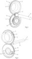
- Figs. 1-4 show parts of an embodiment of an internal combustion engine 1 including variable compression ratio according to the invention.
- Figs. 5-11 show different situations of this embodiment under operating conditions.
- the engine 1 comprises a crankshaft 2 which is rotatably mounted to a crankcase (not shown) and rotatable about a crankshaft axis 3.
- the crankshaft 2 has a crankpin 4 on which an eccentric member 5 is rotatably mounted.
- the eccentric member 5 is rotatable about a centreline of the crankpin 4.
- the eccentric member 5 comprises a bearing portion 6 which has an outer circumferential wall that bears a proximal end portion or a big end of a connecting rod 7.
- the connecting rod 7 is rotatably mounted on the bearing portion 6 and rotatable about a centreline of the bearing portion 6, which is parallel to the centreline of the crankpin 4.
- the bearing portion 6 is eccentrically disposed with respect to the crankpin 4.
- Fig. 4 shows a small circle on the eccentric member 5 which indicates the angular location where the eccentricity of the bearing portion 6 has its maximum. This angular location lies in a plane that is spanned by the centreline of the crankpin 4 and the centreline of the bearing portion 6. Due to the eccentricity the eccentric member 5 has an eccentrical centre of gravity, see Figs. 10 and 11 in which the centre of gravity is indicated by reference sign 5a. In this case the angular location of the centre of gravity 5a is the same as the angular location where the eccentricity of the bearing portion 6 has its maximum.
- the internal combustion engine 1 is further provided with a piston 8 which is rotatably connected to a distal end portion or a small end of the connecting rod 7.
- the engine 1 has a single cylinder but a multi-cylinder is also conceivable.
- the eccentric member 5 is provided with an eccentric member gear 9 which has an axis of rotation that coincides with the centreline of the crankpin 4.
- the eccentric member 5 is drivably coupled to a gear train 10 for rotating the eccentric member 5 with respect to the crankpin 4 at half speed of the speed of the crankshaft 2 and in opposite direction thereof. This means that if the crankshaft 2 rotates twice about the crankshaft axis 3 in clockwise direction, the eccentric member 5 rotates once about the crankpin 4 in anti-clockwise direction.
- the gear train comprises a first stage gear 11 that meshes with the eccentric member gear 9, a second stage gear 12 which is fixed to the first stage gear 11 and an actuating gear 13 which meshes with the second stage gear 12.
- the first stage gear 11 and the second stage gear 12 are rotatably mounted to the crankshaft 2 and have a common axis of rotation.
- the actuating gear 13 is fixed to an actuating shaft 14 that extends through the crankshaft 2.
- the actuating shaft 14 is rotatable with respect to the crankshaft 2 about the crankshaft axis 3.
- a worm wheel 15 is fixed on the actuating shaft 14 and the worm wheel 15 meshes with a worm 16 that is drivable by an electric motor 17.
- the electric motor 17, worm 16 and worm wheel 15 form part of a control mechanism which is drivably coupled to the gear train 10.
- the actuating shaft 14 can be turned by the electric motor 17 in order to vary the compression ratio of the internal combustion engine 1. This provides the opportunity to operate the internal combustion engine 1 at a high compression ratio under low load conditions in order to improve its efficiency. Under high load conditions, the compression ratio can be decreased to avoid detonations. In case of running at fixed compression ratio the actuating shaft 14 has a fixed angular position with respect to the crankcase.
- the eccentrical centre of gravity 5a of the eccentric member 5 When the internal combustion engine 1 is running the eccentrical centre of gravity 5a of the eccentric member 5 generates a centrifugal force on the eccentric member 5, which is directed radially from the crankshaft axis 3.
- the centrifugal force leads to a fluctuating torque about the centreline of the crankpin 4.
- the fluctuating torque is exerted onto the first stage gear 11 by the eccentric member 5 via the eccentric member gear 9.
- the first stage gear 11 is a balancing gear.
- first stage gear 11 has the same number of teeth as the eccentric member gear 9, such that it rotates at the same speed as the eccentric member gear 9 under operating conditions and that the first stage gear 11 has an eccentrical centre of gravity 11a, see Figs. 10 and 11 in which the centre of gravity is indicated by reference sign 11a.
- the centre of gravity 11a of the first stage gear 11 is located such that under operating conditions it causes a counter torque against the torque that is exerted by the eccentric member 5 onto the first stage gear 11 due to the centrifugal force.
- the centre of gravity 11a of the first stage gear 11 is located eccentrically because of the presence of a cavity 18 in the first stage gear 11, but this can be created in an alternative manner.
- the centre of gravity 11a of the first stage gear 11 and the cavity 18 are located at opposite sides of the common axis of rotation of the first stage gear 11 and the second stage gear 12.
- the common axis of rotation of the first stage gear 11 and the second stage gear 12 may be called a balancing gear axis. It is noted that since the first stage gear 11 and the second stage gear 12 are fixed to each other the eccentrical centre of gravity 11a may also be created at the second stage gear 12, for example by creating a cavity in the second stage gear 12.
- Figs. 5-9 show successive situations of the engine 1 under operating conditions when the piston 8 moves from top dead centre, where firing starts, to bottom dead centre, where gas exchange starts, and back to top dead centre where gas exchange stops, hence during one revolution of the crankshaft 2.
- the figures show that during one revolution of the crankshaft 2 in clockwise direction the crank member 5 rotates by a half revolution about the crankpin 4 in anti-clockwise direction.
- Figs. 10 and 11 illustrate the locations of the centres of gravity 5a, 11a of the eccentric member 5 and the first stage gear 11 in the situations as shown in Figs. 5 and 7 , respectively.
- crankshaft axis 3 and the axis of rotation of the first stage gear 11 lie in a balancing gear plane, which coincides with the crank plane because of the arrangement and dimensions of the actuating gear 13, the first stage gear 11, the second stage gear 12 and the eccentric member gear 9. Furthermore, the centre of gravity 11a of the first stage gear 11 is located in the balancing gear plane and lies between the crankshaft axis 3 and the axis of rotation of the first stage gear 11.
- Fig. 10 illustrates the centrifugal forces in the respective centres of gravity 11a and 5a, which centrifugal forces are directed radially from the crankshaft axis 3. Because of the locations of the centre of gravity 11a of the first stage gear 11 and the centre of gravity 5a of the eccentric member 5 the respective centrifugal forces are directed in opposite direction.
- the centrifugal force on the eccentric member 5 is directed through the centreline of the crankpin 4 and the centrifugal force on the first stage gear 11 is directed through its axis of rotation, which means that in this situation they do not generate a torque about the centreline of the crankpin 4 and the axis of rotation of the first stage gear 11, respectively.
- Fig. 11 shows a situation in which the piston 8 is in bottom dead centre. Since the first stage gear 11 and the eccentric member gear 9 mesh with each other the centres of gravity 11a, 5a of the first stage gear 11 and the eccentric member 5 have rotated in opposite directions with respect to each other compared to the situation as shown in Fig. 10 .
- the centre of gravity 5a of the eccentric member 5 lies outside the crank plane that is spanned by the crankshaft axis 3 and the centreline of the crankpin 4, and the centre of gravity 11a of the first stage gear 11 lies outside the balancing gear plane that is spanned by the crankshaft axis 3 and the axis of rotation of the first stage gear 11.
- the centrifugal force in the centre of gravity 5a of the eccentric member 5 generates a torque in clockwise direction which torque is exerted via the eccentric member gear 9 onto the first stage gear 11. Due to the opposite rotational motions of the meshing eccentric member gear 9 and the first stage gear 11 the centrifugal force in the centre of gravity 11a of the first stage gear 11 also generates a torque in clockwise direction which forms a counter torque against the torque that is exerted by the eccentric member gear 9.
- the counter torque avoids that the torque which is exerted by the eccentric member 5 is entirely transferred to the relatively small actuating gear 13 such that its teeth are prevented from overload.
- the first stage gear 11 may be adapted such that the counter torque is smaller than the torque that is generated by the eccentric member.
- Figs. 12 and 13 show a part of an alternative embodiment of the internal combustion engine 1 of the invention.
- the gear train 10 of this embodiment is different from that of the embodiment as shown in Figs. 1-11 .
- the eccentric member gear 9 meshes with an intermediate gear 19, which forms the balancing gear.
- the intermediate gear 19 extends beyond the eccentric member gear 9 such that it also meshes with the actuating gear 13.
- the actuating gear 13 is located in front of the eccentric member gear 9 in axial direction thereof and partly overlaps the eccentric member gear 9.
- crank plane is also spanned by the crankshaft axis 3 and a centreline of the crankpin 4 and the balancing gear plane is also spanned by the crankshaft axis 3 and the axis of rotation of the intermediate gear 19, but the crank plane and the balancing gear plane extend perpendicularly with respect to each other.
- the invention also provides the opportunity to generate a counter torque against a different inertial force onto the eccentric member 5, for example an inertial force that is generated by the piston 8 and/or the connecting rod 7.
- a different inertial force for example an inertial force that is generated by the piston 8 and/or the connecting rod 7.
- the big end of the connecting rod 7 generates a centrifugal force which is directed from the crankshaft axis 3 to its centre of gravity, which at least partly acts onto the eccentric member 5 through the centreline of the bearing portion 6.
- This condition would happen in the situation as shown in Fig. 11 , for example.
- the first stage gear 11 or balancing gear could at least partly compensate the centrifugal force that is generated by the big end.
- inertial forces onto the eccentric member 5 is inertia of the piston 8 and the connecting rod 7 due to their reciprocating motion, which inertial forces are highest in top dead centre and bottom dead centre of the piston 8.
- inertial forces of the piston 8 and the connecting rod 7 are exerted in downward direction onto the eccentric member 5 and are directed through the centreline of the bearing portion 6.
- the resulting torque can at least partly be compensated by the first stage gear 11 or balancing gear.
- the invention provides an effective solution to prevent overload of teeth of the actuating gear due to an inertial force onto the eccentric member, in particular at high engine speed.
- the arrangement and dimensions of the eccentric member gear and the gears of the gear train may be different.
Description
- The present invention relates to an internal combustion engine including variable compression ratio comprising a crankshaft being rotatable about a crankshaft axis and having a crankpin, wherein the crankshaft axis and a centreline of the crankpin span a crank plane, a connecting rod, a piston being rotatably connected to a distal end portion of the connecting rod, an eccentric member being rotatably mounted on the crankpin and comprising a bearing portion having an outer circumferential wall which bears a proximal end portion of the connecting rod such that the connecting rod is rotatably mounted on the bearing portion, wherein the bearing portion is eccentrically disposed with respect to the crankpin and the eccentric member is provided with an eccentric member gear which is drivably coupled to a gear train for rotating the eccentric member with respect to the crankpin.
- Such an internal combustion engine is known from
EP 3 365 544 - Due to the eccentrical arrangement of the bearing portion an inertial force on the eccentric member may lead to a torque about the centreline of the crankpin under operating conditions when the direction of such inertial force is angled with respect to a plane that is spanned by the centreline of the crankpin and a centreline of the bearing portion of the eccentric member. The location of maximum eccentricity of the eccentric member lies in this plane. The torque on the eccentric member is transferred to the gear train and may lead to a relatively high force peak on gear teeth, particularly on gear teeth of the relatively small actuating gear. This drawback typically increases in case of small high-speed engines, which may run at a speed of more than 6000 rpm, for example.
- The present invention aims to improve the internal combustion as described above.
- For this purpose the internal combustion engine according to the invention is characterized in that the gear train comprises a balancing gear which is rotatably mounted to the crankshaft and rotates with respect to the crankshaft about a balancing gear axis at the same speed as the eccentric member gear under operating conditions, wherein the crankshaft axis and the balancing gear axis span a balancing gear plane, wherein the balancing gear has an eccentrical centre of gravity which is located such that under operating conditions it causes a counter torque against a torque that is exerted by the eccentric member gear onto the balancing gear due to an inertial force on the eccentric member.
- The counter torque is generated by a centrifugal force on the balancing gear which has a direction from the crankshaft axis to the centre of gravity of the balancing gear. An advantage of providing a counter torque by the balancing gear is that the torque which is exerted by the eccentric member onto the balancing gear is not or not fully transferred to one or more gears of the gear train which are drivably coupled to the eccentric member gear via the balancing gear. The inertial force on the eccentric member may be generated by inertia of at least one of the piston, the connecting rod and the eccentric member itself.
- For example, when the piston is in bottom dead centre or top dead centre the inertial force of the piston and the connecting rod onto the eccentric member is high; when in this situation a plane that is spanned by the centreline of the crankpin and a centreline of the bearing portion is angled with respect to the direction of the inertial force, the inertial force generates a torque on the eccentric member about the centreline of the crankpin. This torque is transferred to the balancing gear, but due to the invention it is not or not fully transferred further to one or more gears of the gear train which are drivably coupled to the eccentric member gear via the balancing gear. It is noted that the gear train has more than one gear and is adapted such that the balancing gear rotates about the balancing gear axis at the same speed as the eccentric member gear rotates about the crankpin.
- In a preferred embodiment the gear train is adapted such that the eccentric member rotates with respect to the crankpin at half speed of the speed of the crankshaft and in opposite direction thereof, since the relative motion of the eccentric member and the crankpin, on the one hand, and of the eccentric member and the connecting rod, on the other hand, is relatively small, which minimizes friction losses. In fact, bearings between the bearing portion and the connecting rod and between the eccentric member and the crankpin experience half the crankshaft speed.
- The internal combustion engine may also have a control mechanism which is drivably coupled to the gear train in order to vary the compression ratio of the internal combustion engine.
- In a particular embodiment the eccentric member has an eccentrical centre of gravity and the inertial force is a centrifugal force caused by the eccentrical centre of gravity of the eccentric member.
- The centrifugal forces of the eccentric member and the balancing gear in the centres of gravity of the eccentric member and the balancing gear, respectively, are directed radially from the crankshaft axis; centrifugal forces in the centres of gravity due to rotation of the eccentric member about the crankpin and the balancing gear about the balancing gear axis, respectively, are neglected since their rotational speeds are half of the rotational speed of the crankshaft.
- In an embodiment the centre of gravity of the eccentric member lies in a plane that is spanned by the centreline of the crankpin and a centreline of the bearing portion, wherein the eccentric member and the balancing gear are arranged such that when under operating conditions the centre of gravity of the eccentric member lies in the crank plane, the centre of gravity of the balancing gear lies in the balancing gear plane. This synchronizes the torque and counter torque under operating conditions, such that the torque and counter torque increase at the same time and decrease at the same time. When the centre of gravity of the eccentric member lies in the crank plane and the centre of gravity of the balancing gear lies in the balancing gear plane the torque and counter torque are zero. It is noted that in this case there may still be another inertial force than the centrifugal force onto the eccentric member, which generates a torque on the eccentric member.
- In a more specific embodiment, when under operating conditions the centre of gravity of the eccentric member lies in the crank plane and the centreline of the crankpin lies between the crankshaft axis and the centre of gravity of the eccentric member, the centre of gravity of the balancing gear lies between the crankshaft axis and the balancing gear axis.
- The eccentric member gear and the balancing gear may rotate in opposite direction with respect to each other under operating conditions.
- In the event that the eccentric member gear meshes with the balancing gear, they rotate in opposite direction with respect to each other under operating conditions.
- In an embodiment the gear train comprises an actuating gear which is drivably coupled to the balancing gear and fixed to an actuating shaft, wherein the actuating shaft is rotatably mounted to the crankshaft and rotatable about an axis which coincides with the crankshaft axis, wherein under operating conditions the actuating shaft stands still at fixed compression ratio. In practice the actuating gear may be located at the same side of a crank arm of the crankshaft as the eccentric member gear and the balancing gear, whereas the actuating shaft extends through the crankshaft. It is noted that a stand still of the actuating shaft means that the actuating shaft has a fixed position with respect to a crankcase of the internal combustion engine.
- In a compact design of the internal combustion engine the balancing gear is a first stage gear that is fixed to a second stage gear and which has a larger diameter than the second stage gear, wherein the second stage gear meshes with the actuating gear. The second stage gear also forms part of the gear train.
- The crank plane and the balancing gear plane may coincide.
- In an alternative embodiment the balancing gear is an intermediate gear which meshes with the actuating gear. In this case the number of teeth of the intermediate gear equals the number of teeth of the eccentric member gear and equals twice the number of teeth of the actuating gear. The intermediate meshes with the actuating gear and the eccentric member gear.
- The intermediate gear may extend beyond the eccentric member gear, whereas the actuating gear at least partly overlaps the eccentric member gear. This provides the opportunity to design an internal combustion engine including a relatively short stroke.
- The crank plane and the balancing gear plane may be angled with respect to each other.
- The counter torque may be smaller than the torque that is exerted by the eccentric member onto the balancing gear. The level of the counter torque can be adapted by selecting the location of the centre of gravity of the balancing gear.
- It is possible that the counter torque is higher than the torque which is exerted by the eccentric member onto the balancing gear due to the centrifugal force caused by the eccentrical centre of gravity of the eccentric member in order to at least partly balance an additional imbalance, which is caused by another inertial force on the eccentric member. For example, under operating conditions there is also a centrifugal force of the proximal end portion or big end of the connecting rod, which has a direction from the crankshaft axis to its centre of gravity and at least partly acts onto the eccentric member through the centreline of the bearing portion which is located eccentrically with respect to the centreline of the crankpin. This leads to a torque onto the eccentric member when the centrifugal force is angled with respect to the plane that is spanned by the centrelines of the crankpin and the bearing portion. The torque is transferred to the balancing gear; this torque may also at least partly be reduced by selecting an appropriate location of the centre of gravity of the balancing gear. Similarly, it is also possible to balance inertial forces of the piston and/or connecting rod, particularly peak inertial forces at or near top dead centre and bottom dead centre of the piston, in the event that these forces occur at a certain rotational position of the eccentric member, which leads to relatively high torque. Because of several different inertial forces the location of the centre of gravity of the balancing gear may be compromised in practice.
- The eccentrical centre of gravity of the balancing gear may be created by a cavity in the balancing gear, but alternative manners are conceivable. For example, the balancing gear may be thicker at a side of the balancing gear axis where its centre of gravity is intended such that its teeth are also longer at that side.
- The invention will hereafter be elucidated with reference to the schematic drawings showing embodiments of the invention by way of example.
-
Fig. 1 is a side view of a part of an embodiment of an internal combustion engine according to the invention. -
Fig. 2 is a perspective view of the embodiment as shown inFig. 1 . -
Fig. 3 is an enlarged view of a part of the embodiment as shown inFigs. 1 and 2 . -
Fig. 4 is a similar view asFig. 3 , showing the part of the embodiment from a different side. -
Figs. 5-9 are side views of the embodiment as shown inFig. 1 , illustrating different situations under operating conditions. -
Figs. 10 and 11 are similar views asFigs. 5 and 7 , respectively, showing parts thereof. -
Fig. 12 is a similar view asFigs. 5-11 , showing another embodiment on a larger scale. -
Fig. 13 is a perspective view of a part of the embodiment ofFig. 12 . -
Figs. 1-4 show parts of an embodiment of aninternal combustion engine 1 including variable compression ratio according to the invention.Figs. 5-11 show different situations of this embodiment under operating conditions. Theengine 1 comprises acrankshaft 2 which is rotatably mounted to a crankcase (not shown) and rotatable about acrankshaft axis 3. Thecrankshaft 2 has acrankpin 4 on which aneccentric member 5 is rotatably mounted. Theeccentric member 5 is rotatable about a centreline of thecrankpin 4. Theeccentric member 5 comprises a bearingportion 6 which has an outer circumferential wall that bears a proximal end portion or a big end of a connectingrod 7. Hence, the connectingrod 7 is rotatably mounted on the bearingportion 6 and rotatable about a centreline of the bearingportion 6, which is parallel to the centreline of thecrankpin 4. In other words, the bearingportion 6 is eccentrically disposed with respect to thecrankpin 4.Fig. 4 shows a small circle on theeccentric member 5 which indicates the angular location where the eccentricity of the bearingportion 6 has its maximum. This angular location lies in a plane that is spanned by the centreline of thecrankpin 4 and the centreline of the bearingportion 6. Due to the eccentricity theeccentric member 5 has an eccentrical centre of gravity, seeFigs. 10 and 11 in which the centre of gravity is indicated byreference sign 5a. In this case the angular location of the centre ofgravity 5a is the same as the angular location where the eccentricity of the bearingportion 6 has its maximum. - The
internal combustion engine 1 is further provided with apiston 8 which is rotatably connected to a distal end portion or a small end of the connectingrod 7. In this case theengine 1 has a single cylinder but a multi-cylinder is also conceivable. - The
eccentric member 5 is provided with aneccentric member gear 9 which has an axis of rotation that coincides with the centreline of thecrankpin 4. Theeccentric member 5 is drivably coupled to agear train 10 for rotating theeccentric member 5 with respect to thecrankpin 4 at half speed of the speed of thecrankshaft 2 and in opposite direction thereof. This means that if thecrankshaft 2 rotates twice about thecrankshaft axis 3 in clockwise direction, theeccentric member 5 rotates once about thecrankpin 4 in anti-clockwise direction. - In the embodiment as shown in
Figs. 1-11 the gear train comprises afirst stage gear 11 that meshes with theeccentric member gear 9, asecond stage gear 12 which is fixed to thefirst stage gear 11 and anactuating gear 13 which meshes with thesecond stage gear 12. Thefirst stage gear 11 and thesecond stage gear 12 are rotatably mounted to thecrankshaft 2 and have a common axis of rotation. Theactuating gear 13 is fixed to anactuating shaft 14 that extends through thecrankshaft 2. The actuatingshaft 14 is rotatable with respect to thecrankshaft 2 about thecrankshaft axis 3. - A
worm wheel 15 is fixed on theactuating shaft 14 and theworm wheel 15 meshes with aworm 16 that is drivable by anelectric motor 17. Theelectric motor 17,worm 16 andworm wheel 15 form part of a control mechanism which is drivably coupled to thegear train 10. The actuatingshaft 14 can be turned by theelectric motor 17 in order to vary the compression ratio of theinternal combustion engine 1. This provides the opportunity to operate theinternal combustion engine 1 at a high compression ratio under low load conditions in order to improve its efficiency. Under high load conditions, the compression ratio can be decreased to avoid detonations. In case of running at fixed compression ratio the actuatingshaft 14 has a fixed angular position with respect to the crankcase. - When the
internal combustion engine 1 is running the eccentrical centre ofgravity 5a of theeccentric member 5 generates a centrifugal force on theeccentric member 5, which is directed radially from thecrankshaft axis 3. During periods in which the centre ofgravity 5a of theeccentric member 5 lies outside a crank plane in which thecrankshaft axis 3 and the centreline of thecrankpin 4 lie, the centrifugal force leads to a fluctuating torque about the centreline of thecrankpin 4. The fluctuating torque is exerted onto thefirst stage gear 11 by theeccentric member 5 via theeccentric member gear 9. In order to at least partly reduce transferal of the fluctuating torque via thesecond stage gear 12 to the relativelysmall actuating gear 13 so as to avoid overload of its gear teeth, thefirst stage gear 11 is a balancing gear. This means that thefirst stage gear 11 has the same number of teeth as theeccentric member gear 9, such that it rotates at the same speed as theeccentric member gear 9 under operating conditions and that thefirst stage gear 11 has an eccentrical centre ofgravity 11a, seeFigs. 10 and 11 in which the centre of gravity is indicated byreference sign 11a. - Furthermore, the centre of
gravity 11a of thefirst stage gear 11 is located such that under operating conditions it causes a counter torque against the torque that is exerted by theeccentric member 5 onto thefirst stage gear 11 due to the centrifugal force. In this case the centre ofgravity 11a of thefirst stage gear 11 is located eccentrically because of the presence of acavity 18 in thefirst stage gear 11, but this can be created in an alternative manner. The centre ofgravity 11a of thefirst stage gear 11 and thecavity 18 are located at opposite sides of the common axis of rotation of thefirst stage gear 11 and thesecond stage gear 12. The common axis of rotation of thefirst stage gear 11 and thesecond stage gear 12 may be called a balancing gear axis. It is noted that since thefirst stage gear 11 and thesecond stage gear 12 are fixed to each other the eccentrical centre ofgravity 11a may also be created at thesecond stage gear 12, for example by creating a cavity in thesecond stage gear 12. -
Figs. 5-9 show successive situations of theengine 1 under operating conditions when thepiston 8 moves from top dead centre, where firing starts, to bottom dead centre, where gas exchange starts, and back to top dead centre where gas exchange stops, hence during one revolution of thecrankshaft 2. The figures show that during one revolution of thecrankshaft 2 in clockwise direction thecrank member 5 rotates by a half revolution about thecrankpin 4 in anti-clockwise direction.Figs. 10 and 11 illustrate the locations of the centres ofgravity eccentric member 5 and thefirst stage gear 11 in the situations as shown inFigs. 5 and 7 , respectively. - In the situation as shown in
Figs. 5 and10 thecrankshaft axis 3, the centreline of thecrankpin 4 and the centre ofgravity 5a of theeccentric member 5 lie in the crank plane, whereas the centreline of thecrankpin 4 lies between thecrankshaft axis 3 and the centre ofgravity 5a of theeccentric member 5. In this situation thecrankshaft axis 3 and the axis of rotation of thefirst stage gear 11 lie in a balancing gear plane, which coincides with the crank plane because of the arrangement and dimensions of theactuating gear 13, thefirst stage gear 11, thesecond stage gear 12 and theeccentric member gear 9. Furthermore, the centre ofgravity 11a of thefirst stage gear 11 is located in the balancing gear plane and lies between thecrankshaft axis 3 and the axis of rotation of thefirst stage gear 11. -
Fig. 10 illustrates the centrifugal forces in the respective centres ofgravity crankshaft axis 3. Because of the locations of the centre ofgravity 11a of thefirst stage gear 11 and the centre ofgravity 5a of theeccentric member 5 the respective centrifugal forces are directed in opposite direction. The centrifugal force on theeccentric member 5 is directed through the centreline of thecrankpin 4 and the centrifugal force on thefirst stage gear 11 is directed through its axis of rotation, which means that in this situation they do not generate a torque about the centreline of thecrankpin 4 and the axis of rotation of thefirst stage gear 11, respectively. It is noted that the centrifugal forces in the centres ofgravity eccentric member 5 about thecrankpin 4 and thefirst stage gear 11 about its axis of rotation are neglected since their rotational speeds are half of the rotational speed of thecrankshaft 2. Besides, they do not result in a torque on theeccentric member 5 and thefirst stage gear 11. -
Fig. 11 shows a situation in which thepiston 8 is in bottom dead centre. Since thefirst stage gear 11 and theeccentric member gear 9 mesh with each other the centres ofgravity first stage gear 11 and theeccentric member 5 have rotated in opposite directions with respect to each other compared to the situation as shown inFig. 10 . In the situation as shown inFig. 11 the centre ofgravity 5a of theeccentric member 5 lies outside the crank plane that is spanned by thecrankshaft axis 3 and the centreline of thecrankpin 4, and the centre ofgravity 11a of thefirst stage gear 11 lies outside the balancing gear plane that is spanned by thecrankshaft axis 3 and the axis of rotation of thefirst stage gear 11. - The centrifugal force in the centre of
gravity 5a of theeccentric member 5 generates a torque in clockwise direction which torque is exerted via theeccentric member gear 9 onto thefirst stage gear 11. Due to the opposite rotational motions of the meshingeccentric member gear 9 and thefirst stage gear 11 the centrifugal force in the centre ofgravity 11a of thefirst stage gear 11 also generates a torque in clockwise direction which forms a counter torque against the torque that is exerted by theeccentric member gear 9. The counter torque avoids that the torque which is exerted by theeccentric member 5 is entirely transferred to the relativelysmall actuating gear 13 such that its teeth are prevented from overload. In practice thefirst stage gear 11 may be adapted such that the counter torque is smaller than the torque that is generated by the eccentric member. -
Figs. 12 and 13 show a part of an alternative embodiment of theinternal combustion engine 1 of the invention. thegear train 10 of this embodiment is different from that of the embodiment as shown inFigs. 1-11 . Theeccentric member gear 9 meshes with anintermediate gear 19, which forms the balancing gear. Theintermediate gear 19 extends beyond theeccentric member gear 9 such that it also meshes with theactuating gear 13. Theactuating gear 13 is located in front of theeccentric member gear 9 in axial direction thereof and partly overlaps theeccentric member gear 9. In this case the crank plane is also spanned by thecrankshaft axis 3 and a centreline of thecrankpin 4 and the balancing gear plane is also spanned by thecrankshaft axis 3 and the axis of rotation of theintermediate gear 19, but the crank plane and the balancing gear plane extend perpendicularly with respect to each other. - In the situation as shown in
Fig. 12 the centre ofgravity 5a of theeccentric member 5 lies at a side of the crank plane which is directed clockwise and the centre of gravity of theintermediate gear 19 lies at a side of the balancing gear plane which is directed clockwise such that the centrifugal force on theeccentric member 5 generates a torque in anti-clockwise direction about the centreline of thecrankpin 4 and the centrifugal force on theintermediate gear 19 generates a counter torque in anti-clockwise direction about the axis of rotation of theintermediate gear 19. - The invention also provides the opportunity to generate a counter torque against a different inertial force onto the
eccentric member 5, for example an inertial force that is generated by thepiston 8 and/or the connectingrod 7. For example, under operating conditions the big end of the connectingrod 7 generates a centrifugal force which is directed from thecrankshaft axis 3 to its centre of gravity, which at least partly acts onto theeccentric member 5 through the centreline of the bearingportion 6. This leads to a torque on theeccentric member 5 when the direction of this centrifugal force is angled with the plane that is spanned by the centrelines of thecrankpin 4 and the bearingportion 6. This condition would happen in the situation as shown inFig. 11 , for example. Hence, even if theeccentric member 5 was balanced itself by having its centre ofgravity 5a at the centreline of thecrankpin 4, thefirst stage gear 11 or balancing gear could at least partly compensate the centrifugal force that is generated by the big end. - Another example of other inertial forces onto the
eccentric member 5 is inertia of thepiston 8 and the connectingrod 7 due to their reciprocating motion, which inertial forces are highest in top dead centre and bottom dead centre of thepiston 8. For example, in the situation as shown inFig. 11 the inertial forces of thepiston 8 and the connectingrod 7 are exerted in downward direction onto theeccentric member 5 and are directed through the centreline of the bearingportion 6. This leads to a torque on theeccentric member 5 since the direction of the inertial forces are angled with respect to the plane that is spanned by the centrelines of thecrankpin 4 and the bearingportion 6. The resulting torque can at least partly be compensated by thefirst stage gear 11 or balancing gear. - From the foregoing, it will be clear that the invention provides an effective solution to prevent overload of teeth of the actuating gear due to an inertial force onto the eccentric member, in particular at high engine speed.
- The invention is not limited to the embodiments shown in the drawings and described hereinbefore, which may be varied in different manners within the scope of the appended claims, defining the invention.
- For example, the arrangement and dimensions of the eccentric member gear and the gears of the gear train may be different.
Claims (15)
- An internal combustion engine (1) including variable compression ratio comprisinga crankshaft (2) being rotatable about a crankshaft axis (3) and having a crankpin (4), wherein the crankshaft axis (3) and a centreline of the crankpin (4) span a crank plane,a connecting rod (4),a piston (8) being rotatably connected to a distal end portion of the connecting rod (4);an eccentric member (5) being rotatably mounted on the crankpin (4) and comprising a bearing portion (6) having an outer circumferential wall which bears a proximal end portion of the connecting rod (4) such that the connecting rod (4) is rotatably mounted on the bearing portion (6), wherein the bearing portion (9) is eccentrically disposed with respect to the crankpin (4) and the eccentric member (5) is provided with an eccentric member gear (9) which is drivably coupled to a gear train (10) for rotating the eccentric member (5) with respect to the crankpin (4), characterized in that the gear train (10) comprises a balancing gear (11, 19) which is rotatably mounted to the crankshaft (2) and rotates with respect to the crankshaft (2) about a balancing gear axis at the same speed as the eccentric member gear (9) under operating conditions, wherein the crankshaft axis (3) and the balancing gear axis span a balancing gear plane, wherein the balancing gear (11) has an eccentrical centre of gravity (11a) which is located such that under operating conditions it causes a counter torque against a torque that is exerted by the eccentric member gear (9) onto the balancing gear (11, 19) due to an inertial force on the eccentric member (5).
- An internal combustion engine (1) according to claim 1, wherein the gear train (10) is adapted such that the eccentric member (5) rotates with respect to the crankpin (4) at half speed of the speed of the crankshaft (2) and in opposite direction thereof.
- An internal combustion engine (1) according to claim 1 or 2, wherein the eccentric member (5) has an eccentrical centre of gravity (5a) and the inertial force is a centrifugal force caused by the eccentrical centre of gravity (5a) of the eccentric member (5).
- An internal combustion engine (1) according to claim 3, wherein the centre of gravity (5a) of the eccentric member (5) lies in a plane that is spanned by the centreline of the crankpin (4) and a centreline of the bearing portion (6), wherein the eccentric member (5) and the balancing gear (11, 19) are arranged such that when under operating conditions the centre of gravity (5a) of the eccentric member (5) lies in the crank plane, the centre of gravity (11a) of the balancing gear (11, 19) lies in the balancing gear plane.
- An internal combustion engine (1) according to claim 4, wherein when under operating conditions the centre of gravity (5a) of the eccentric member (5) lies in the crank plane and the centreline of the crankpin (4) lies between the crankshaft axis (3) and the centre of gravity (5a) of the eccentric member (5), the centre of gravity (11a) of the balancing gear (11, 19) lies between the crankshaft axis (3) and the balancing gear axis.
- An internal combustion engine (1) according to any one of the preceding claims, wherein the eccentric member gear (9) and the balancing gear (11, 19) rotate in opposite direction with respect to each other under operating conditions.
- An internal combustion engine (1) according to claim 6, wherein the eccentric member gear (5) meshes with the balancing gear (11, 19).
- An internal combustion engine (1) according to claim 7, wherein the gear train (10) comprises an actuating gear (13) which is drivably coupled to the balancing gear (11, 19) and fixed to an actuating shaft (14), wherein the actuating shaft (14) is rotatably mounted to the crankshaft (3) and rotatable about an axis which coincides with the crankshaft axis (3), wherein under operating conditions the actuating shaft (14) stands still at fixed compression ratio.
- An internal combustion engine (1) according to claim 8, wherein the balancing gear is a first stage gear (11) that is fixed to a second stage gear (12) and which has a larger diameter than the second stage gear (12), wherein the second stage gear (12) meshes with the actuating gear (13).
- An internal combustion engine (1) according to any one of the preceding claims, wherein the crank plane and the balancing gear plane coincide.
- An internal combustion engine (1) according to any one of the claims 1-5 and claim 8, wherein the balancing gear is an intermediate gear (19) which meshes with the actuating gear (13).
- An internal combustion engine (1) according to claim 11, wherein the intermediate gear (19) extends beyond the eccentric member gear (9) and the actuating gear at least partly overlaps the eccentric member gear (9).
- An internal combustion engine (1) according to claim 11 or 12, wherein the crank plane and the balancing gear plane are angled with respect to each other.
- An internal combustion engine according to any one of the preceding claims, wherein the counter torque is smaller than the torque that is exerted by the eccentric member (5) onto the balancing gear (11, 19).
- An internal combustion engine according to any one of the preceding claims, wherein the centre of gravity (11a) of the balancing gear (11) is created by a cavity (18) in the balancing gear (11).
Priority Applications (2)
| Application Number | Priority Date | Filing Date | Title |
|---|---|---|---|
| EP20210071.5A EP4006323B1 (en) | 2020-11-26 | 2020-11-26 | An internal combustion engine including variable compression ratio |
| PCT/EP2021/082736 WO2022112275A1 (en) | 2020-11-26 | 2021-11-24 | An internal combustion engine including variable compression ratio |
Applications Claiming Priority (1)
| Application Number | Priority Date | Filing Date | Title |
|---|---|---|---|
| EP20210071.5A EP4006323B1 (en) | 2020-11-26 | 2020-11-26 | An internal combustion engine including variable compression ratio |
Publications (2)
| Publication Number | Publication Date |
|---|---|
| EP4006323A1 EP4006323A1 (en) | 2022-06-01 |
| EP4006323B1 true EP4006323B1 (en) | 2023-06-07 |
Family
ID=73598768
Family Applications (1)
| Application Number | Title | Priority Date | Filing Date |
|---|---|---|---|
| EP20210071.5A Active EP4006323B1 (en) | 2020-11-26 | 2020-11-26 | An internal combustion engine including variable compression ratio |
Country Status (1)
| Country | Link |
|---|---|
| EP (1) | EP4006323B1 (en) |
Family Cites Families (5)
| Publication number | Priority date | Publication date | Assignee | Title |
|---|---|---|---|---|
| DE164819C (en) * | 1904-08-02 | 1905-11-16 | ||
| EP1983215A1 (en) * | 2007-04-20 | 2008-10-22 | Gomecsys B.V. | Reciprocating piston machine and internal combustion engine |
| EP2905448A1 (en) * | 2014-02-11 | 2015-08-12 | Gomecsys B.V. | An internal combustion engine including variable compression ratio and a method of operating the engine |
| FR3042816B1 (en) | 2015-10-22 | 2017-12-08 | Peugeot Citroen Automobiles Sa | THERMAL MOTOR PROVIDED WITH A SYSTEM OF VARIATION OF THE COMPRESSION RATE |
| EP3726023A1 (en) * | 2019-04-17 | 2020-10-21 | Gomecsys B.V. | An internal combustion engine |
-
2020
- 2020-11-26 EP EP20210071.5A patent/EP4006323B1/en active Active
Also Published As
| Publication number | Publication date |
|---|---|
| EP4006323A1 (en) | 2022-06-01 |
Similar Documents
| Publication | Publication Date | Title |
|---|---|---|
| EP2454458B1 (en) | A reciprocating piston mechanism | |
| EP2257700B1 (en) | A reciprocating piston mechanism and a method of increasing internal egr in an internal combustion engine | |
| EP1983215A1 (en) | Reciprocating piston machine and internal combustion engine | |
| KR102210231B1 (en) | Power unit | |
| KR20170080606A (en) | Power unit | |
| EP2025893A1 (en) | A reciprocating piston mechanism | |
| EP2905448A1 (en) | An internal combustion engine including variable compression ratio and a method of operating the engine | |
| EP2902603A1 (en) | An internal combustion engine including variable compression ratio | |
| US8783222B2 (en) | Apparatus and method of control of balance shafts in an engine | |
| WO2006102314A2 (en) | Hypocycloid device | |
| CN101532550A (en) | Balance shaft drive system | |
| US9103333B2 (en) | Axial piston machines | |
| EP4006323B1 (en) | An internal combustion engine including variable compression ratio | |
| WO2000006870A2 (en) | Engine balance apparatus and accessory drive device | |
| WO2022112275A1 (en) | An internal combustion engine including variable compression ratio | |
| EP4183992A1 (en) | An eccentric member and an internal combustion engine | |
| JP2009121540A (en) | Crank device | |
| JP2011069301A (en) | Internal combustion engine | |
| JP2011102602A (en) | Balance device in internal combustion engine | |
| US20220243646A1 (en) | Charged serial hybrid combustion engine | |
| EP3540270A1 (en) | A gear train and an internal combustion engine | |
| JPH0640995Y2 (en) | Balancing device for internal combustion engine | |
| JP5552198B1 (en) | Internal combustion engine | |
| JP2019173717A (en) | Mechanical supercharger for internal combustion engine | |
| KR19980036735U (en) | Balance shaft structure of internal combustion engine |
Legal Events
| Date | Code | Title | Description |
|---|---|---|---|
| PUAI | Public reference made under article 153(3) epc to a published international application that has entered the european phase |
Free format text: ORIGINAL CODE: 0009012 |
|
| STAA | Information on the status of an ep patent application or granted ep patent |
Free format text: STATUS: THE APPLICATION HAS BEEN PUBLISHED |
|
| AK | Designated contracting states |
Kind code of ref document: A1 Designated state(s): AL AT BE BG CH CY CZ DE DK EE ES FI FR GB GR HR HU IE IS IT LI LT LU LV MC MK MT NL NO PL PT RO RS SE SI SK SM TR |
|
| STAA | Information on the status of an ep patent application or granted ep patent |
Free format text: STATUS: REQUEST FOR EXAMINATION WAS MADE |
|
| 17P | Request for examination filed |
Effective date: 20221018 |
|
| RBV | Designated contracting states (corrected) |
Designated state(s): AL AT BE BG CH CY CZ DE DK EE ES FI FR GB GR HR HU IE IS IT LI LT LU LV MC MK MT NL NO PL PT RO RS SE SI SK SM TR |
|
| GRAP | Despatch of communication of intention to grant a patent |
Free format text: ORIGINAL CODE: EPIDOSNIGR1 |
|
| STAA | Information on the status of an ep patent application or granted ep patent |
Free format text: STATUS: GRANT OF PATENT IS INTENDED |
|
| INTG | Intention to grant announced |
Effective date: 20221212 |
|
| GRAS | Grant fee paid |
Free format text: ORIGINAL CODE: EPIDOSNIGR3 |
|
| GRAA | (expected) grant |
Free format text: ORIGINAL CODE: 0009210 |
|
| STAA | Information on the status of an ep patent application or granted ep patent |
Free format text: STATUS: THE PATENT HAS BEEN GRANTED |
|
| AK | Designated contracting states |
Kind code of ref document: B1 Designated state(s): AL AT BE BG CH CY CZ DE DK EE ES FI FR GB GR HR HU IE IS IT LI LT LU LV MC MK MT NL NO PL PT RO RS SE SI SK SM TR |
|
| REG | Reference to a national code |
Ref country code: GB Ref legal event code: FG4D |
|
| REG | Reference to a national code |
Ref country code: CH Ref legal event code: EP Ref country code: AT Ref legal event code: REF Ref document number: 1575736 Country of ref document: AT Kind code of ref document: T Effective date: 20230615 Ref country code: DE Ref legal event code: R096 Ref document number: 602020011779 Country of ref document: DE |
|
| REG | Reference to a national code |
Ref country code: LT Ref legal event code: MG9D |
|
| REG | Reference to a national code |
Ref country code: NL Ref legal event code: MP Effective date: 20230607 |
|
| PG25 | Lapsed in a contracting state [announced via postgrant information from national office to epo] |
Ref country code: SE Free format text: LAPSE BECAUSE OF FAILURE TO SUBMIT A TRANSLATION OF THE DESCRIPTION OR TO PAY THE FEE WITHIN THE PRESCRIBED TIME-LIMIT Effective date: 20230607 Ref country code: NO Free format text: LAPSE BECAUSE OF FAILURE TO SUBMIT A TRANSLATION OF THE DESCRIPTION OR TO PAY THE FEE WITHIN THE PRESCRIBED TIME-LIMIT Effective date: 20230907 Ref country code: ES Free format text: LAPSE BECAUSE OF FAILURE TO SUBMIT A TRANSLATION OF THE DESCRIPTION OR TO PAY THE FEE WITHIN THE PRESCRIBED TIME-LIMIT Effective date: 20230607 |
|
| REG | Reference to a national code |
Ref country code: AT Ref legal event code: MK05 Ref document number: 1575736 Country of ref document: AT Kind code of ref document: T Effective date: 20230607 |
|
| PG25 | Lapsed in a contracting state [announced via postgrant information from national office to epo] |
Ref country code: RS Free format text: LAPSE BECAUSE OF FAILURE TO SUBMIT A TRANSLATION OF THE DESCRIPTION OR TO PAY THE FEE WITHIN THE PRESCRIBED TIME-LIMIT Effective date: 20230607 Ref country code: NL Free format text: LAPSE BECAUSE OF FAILURE TO SUBMIT A TRANSLATION OF THE DESCRIPTION OR TO PAY THE FEE WITHIN THE PRESCRIBED TIME-LIMIT Effective date: 20230607 Ref country code: LV Free format text: LAPSE BECAUSE OF FAILURE TO SUBMIT A TRANSLATION OF THE DESCRIPTION OR TO PAY THE FEE WITHIN THE PRESCRIBED TIME-LIMIT Effective date: 20230607 Ref country code: LT Free format text: LAPSE BECAUSE OF FAILURE TO SUBMIT A TRANSLATION OF THE DESCRIPTION OR TO PAY THE FEE WITHIN THE PRESCRIBED TIME-LIMIT Effective date: 20230607 Ref country code: HR Free format text: LAPSE BECAUSE OF FAILURE TO SUBMIT A TRANSLATION OF THE DESCRIPTION OR TO PAY THE FEE WITHIN THE PRESCRIBED TIME-LIMIT Effective date: 20230607 Ref country code: GR Free format text: LAPSE BECAUSE OF FAILURE TO SUBMIT A TRANSLATION OF THE DESCRIPTION OR TO PAY THE FEE WITHIN THE PRESCRIBED TIME-LIMIT Effective date: 20230908 |
|
| PG25 | Lapsed in a contracting state [announced via postgrant information from national office to epo] |
Ref country code: FI Free format text: LAPSE BECAUSE OF FAILURE TO SUBMIT A TRANSLATION OF THE DESCRIPTION OR TO PAY THE FEE WITHIN THE PRESCRIBED TIME-LIMIT Effective date: 20230607 |
|
| PG25 | Lapsed in a contracting state [announced via postgrant information from national office to epo] |
Ref country code: SK Free format text: LAPSE BECAUSE OF FAILURE TO SUBMIT A TRANSLATION OF THE DESCRIPTION OR TO PAY THE FEE WITHIN THE PRESCRIBED TIME-LIMIT Effective date: 20230607 |
|
| PG25 | Lapsed in a contracting state [announced via postgrant information from national office to epo] |
Ref country code: IS Free format text: LAPSE BECAUSE OF FAILURE TO SUBMIT A TRANSLATION OF THE DESCRIPTION OR TO PAY THE FEE WITHIN THE PRESCRIBED TIME-LIMIT Effective date: 20231007 |
|
| PG25 | Lapsed in a contracting state [announced via postgrant information from national office to epo] |
Ref country code: SM Free format text: LAPSE BECAUSE OF FAILURE TO SUBMIT A TRANSLATION OF THE DESCRIPTION OR TO PAY THE FEE WITHIN THE PRESCRIBED TIME-LIMIT Effective date: 20230607 Ref country code: SK Free format text: LAPSE BECAUSE OF FAILURE TO SUBMIT A TRANSLATION OF THE DESCRIPTION OR TO PAY THE FEE WITHIN THE PRESCRIBED TIME-LIMIT Effective date: 20230607 Ref country code: RO Free format text: LAPSE BECAUSE OF FAILURE TO SUBMIT A TRANSLATION OF THE DESCRIPTION OR TO PAY THE FEE WITHIN THE PRESCRIBED TIME-LIMIT Effective date: 20230607 Ref country code: PT Free format text: LAPSE BECAUSE OF FAILURE TO SUBMIT A TRANSLATION OF THE DESCRIPTION OR TO PAY THE FEE WITHIN THE PRESCRIBED TIME-LIMIT Effective date: 20231009 Ref country code: IS Free format text: LAPSE BECAUSE OF FAILURE TO SUBMIT A TRANSLATION OF THE DESCRIPTION OR TO PAY THE FEE WITHIN THE PRESCRIBED TIME-LIMIT Effective date: 20231007 Ref country code: EE Free format text: LAPSE BECAUSE OF FAILURE TO SUBMIT A TRANSLATION OF THE DESCRIPTION OR TO PAY THE FEE WITHIN THE PRESCRIBED TIME-LIMIT Effective date: 20230607 Ref country code: CZ Free format text: LAPSE BECAUSE OF FAILURE TO SUBMIT A TRANSLATION OF THE DESCRIPTION OR TO PAY THE FEE WITHIN THE PRESCRIBED TIME-LIMIT Effective date: 20230607 Ref country code: AT Free format text: LAPSE BECAUSE OF FAILURE TO SUBMIT A TRANSLATION OF THE DESCRIPTION OR TO PAY THE FEE WITHIN THE PRESCRIBED TIME-LIMIT Effective date: 20230607 |
|
| PGFP | Annual fee paid to national office [announced via postgrant information from national office to epo] |
Ref country code: FR Payment date: 20231127 Year of fee payment: 4 Ref country code: DE Payment date: 20231129 Year of fee payment: 4 |
|
| PG25 | Lapsed in a contracting state [announced via postgrant information from national office to epo] |
Ref country code: PL Free format text: LAPSE BECAUSE OF FAILURE TO SUBMIT A TRANSLATION OF THE DESCRIPTION OR TO PAY THE FEE WITHIN THE PRESCRIBED TIME-LIMIT Effective date: 20230607 |
|
| PLBE | No opposition filed within time limit |
Free format text: ORIGINAL CODE: 0009261 |
|
| STAA | Information on the status of an ep patent application or granted ep patent |
Free format text: STATUS: NO OPPOSITION FILED WITHIN TIME LIMIT |