EP4344404B1 - Rückkopplungskühlsystem für ein bildgebungssystem - Google Patents
Rückkopplungskühlsystem für ein bildgebungssystem Download PDFInfo
- Publication number
- EP4344404B1 EP4344404B1 EP21745669.8A EP21745669A EP4344404B1 EP 4344404 B1 EP4344404 B1 EP 4344404B1 EP 21745669 A EP21745669 A EP 21745669A EP 4344404 B1 EP4344404 B1 EP 4344404B1
- Authority
- EP
- European Patent Office
- Prior art keywords
- air
- temperature
- cooling system
- component
- mixed
- Prior art date
- Legal status (The legal status is an assumption and is not a legal conclusion. Google has not performed a legal analysis and makes no representation as to the accuracy of the status listed.)
- Active
Links
Images


Classifications
-
- A—HUMAN NECESSITIES
- A61—MEDICAL OR VETERINARY SCIENCE; HYGIENE
- A61B—DIAGNOSIS; SURGERY; IDENTIFICATION
- A61B6/00—Apparatus or devices for radiation diagnosis; Apparatus or devices for radiation diagnosis combined with radiation therapy equipment
- A61B6/02—Arrangements for diagnosis sequentially in different planes; Stereoscopic radiation diagnosis
- A61B6/03—Computed tomography [CT]
- A61B6/037—Emission tomography
-
- A—HUMAN NECESSITIES
- A61—MEDICAL OR VETERINARY SCIENCE; HYGIENE
- A61B—DIAGNOSIS; SURGERY; IDENTIFICATION
- A61B6/00—Apparatus or devices for radiation diagnosis; Apparatus or devices for radiation diagnosis combined with radiation therapy equipment
- A61B6/44—Constructional features of apparatus for radiation diagnosis
- A61B6/4488—Means for cooling
Definitions
- aspects of the present invention relate to a cooling system for an imaging system, and more particularly, to a cooling system for cooling at least one component of the imaging system wherein the cooling system uses a portion of warm air from an outlet of the component that is then recirculated and mixed with scan room air to provide air within a narrow temperature range that flows at a high air flow rate to cool the component.
- PET/CT imaging systems are cooled by a cooling media such as liquid, air or a combination of liquid and air.
- a cooling media such as liquid, air or a combination of liquid and air.
- the room temperature range required for proper operation of the imaging system is frequently too narrow for the needs of the customer site.
- Some customer sites have a room temperature that is lower than the required lower temperature limit for proper operation of the imaging system whereas other sites have a room temperature that is above the required upper limit for proper operation of the imaging system.
- warning and error indications are generated by the imaging system which may cause the imaging system to undesirably shut down.
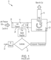
- the conventional method to cooling has been to drive air in an open loop by controlling fan speed which changes the air flow rate through the cooling system 10.
- fan speed is reduced when the scan room is relatively cold and then increased as the scan room temperature rises.
- internal imaging system temperatures change with room temperature. When fan speed decreases, the internal imaging system temperature increases and when fan speed increases, the internal imaging system temperatures decrease.
- the cooling system 10 is driven by the ambient air room temperature and the heat load generated by the imaging system which may result in the exposure of internal imaging system components to a wide range of temperatures.
- the range of controlled temperatures is normally set at a relatively wide temperature range (24-38°C, or 15°C for example) since this is a function of the ambient air temperature (18-30°C, for example) and the heat being dissipated in the imaging system.
- the cooling system 10 may not be able to maintain the temperature of the components being cooled in their operating or targeted range when the ambient air room temperature goes outside specified limits.
- a temperature compensation circuit having a detector compensation algorithm is utilized to correct for temperature variability in the detector.
- the targeted temperature range i.e., the range of controlled temperatures
- the detector compensation algorithm becomes more difficult to characterize.
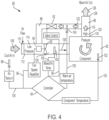
- a cooling system for cooling at least one component of an imaging system located in a scan room includes inlet and outlet channels in air flow communication with the component and a return channel in air flow communication with the inlet and outlet channels, wherein a portion of warm outlet air from a component outlet flows in the return channel to provide warm recirculated air to a mixing zone in the inlet channel.
- the system also includes a fan located in the inlet channel that draws scan room air into the inlet channel wherein the room air is mixed with the warm recirculated air in the mixing zone to form mixed air that flows over the component to cool the component and wherein the mixed air absorbs heat that warms the mixed air to form the warm outlet air.
- the system includes a valve located in the return channel, wherein the valve restricts or allows additional warm recirculated air to flow through the return channel to the mixing zone to mix with the scan room air to maintain a desired control temperature for the cooling system.
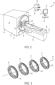
- the PET portion 36 includes a plurality of PET detector rings 66 arranged about the longitudinal axis 42.
- exemplary first 68, second 70, third 72 and fourth 74 detector rings are shown.
- Each detector ring 68, 70, 72, 74 includes a plurality of PET detectors 66 used to scan the patient 46 located in the tunnel 52.
- a patient 46 located in the tunnel 52 is injected with a radioisotope.
- the radioisotope undergoes positron emission decay and emits a positron that encounters and annihilates with an electron to produce a pair of gamma rays moving in approximately opposite directions.
- the gamma rays are detected by the PET detectors 66 and information from the gamma rays is used to generate PET images.
- the PET images are then used in conjunction with CT images generated by the CT portion 34 of imaging system 32 to provide images of the patient 46 or part of a patient's anatomy.
- Each PET detector 66 generates heat during operation of the PET portion 36.
- the cooling system 80 includes inlet 84 and outlet 86 channels that are in air flow communication with the component 82 to be cooled and a return channel 88 that is in air flow communication with the outlet 86 and inlet 84 channels.
- the cooling system 80 also includes at least one variable speed fan 90 and at least one valve 92 that are each connected to a controller 94 by respective control lines 96.
- the fan 90 is located in the inlet channel 84 and the valve 92 is located in the return channel 88.
- the fan 90 and valve 92 may be located in other suitable positions in the cooling system 80 in addition to or instead of the inlet 84 and return 88 channels.
- the cooling system 80 further includes first 98, second 100, third 102 and fourth 104 temperature sensors located in the scan room, the inlet channel 84, on the component 82 and in the return channel 88, respectively, that provide temperature data to the controller via respective signal lines 105 connected between the first 98, second 100, third 102 and fourth 104 temperature sensors and the controller 94.
- the valve 92 is an electronically actuated valve controlled by the controller 94 to partially open as desired. In an embodiment, the valve 92 may be an electronically actuated butterfly valve.
- the controller 94 also controls a fan speed of the fan 90 to provide a desired flow of mixed air 106 to the component 82.
- the fan 90 draws in scan room ambient air 108 at atmospheric pressure through a filter 110 located on an inlet end 112 of the inlet channel 84.
- the room air 108 then flows through a low pressure zone 114 formed before the fan 90 and subsequently past the fan 90 and the component 82 to dissipate heat from the component 82.
- This cools the component 82 and forms warm outlet air 116 that exits a component outlet 118 at high pressure 120.
- the valve 92 is partially opened, a portion of warm outlet air 116 from the component outlet 118 flows through the return channel 88 to provide warm recirculated air 122 to an air mixing zone 124 in the inlet channel 84.
- the warm recirculated air 122 is mixed with the room air 108 by the fan 90 to form mixed air 106 that subsequently flows past the component 82 to cool the component 82 and forms the warm outlet air 116.
- the mixing of warm recirculated air 122 with room air 108 provides mixed air 106 that is warmer than the room air 108.
- the second temperature sensor 100 is positioned in the inlet channel 84 after the mixing zone 124 to provide mixed air temperature data to the controller 94.
- the controller 94 may vary a valve opening of the valve 92 to restrict or allow additional warm recirculated air 122 into the return channel 88 and subsequently the mixing zone 124 based on the detected mixed air temperature provided by the second temperature sensor 100 in order to maintain a desired target or control temperature.
- the controller 94 may also adjust a fan speed of the fan 90 in order to maintain the control temperature and/or provide a desired air flow rate.
- this provides a range of control temperatures for the mixed air 106 that is sufficient for cooling the component 82 and narrower than in conventional cooling systems.
- a control temperature of the cooling system can be set at a higher temperature to enable higher air flow into the cooling system.
- Fig. 5A is a schematic representation of a temperature gradient 130 in an axial direction 132 substantially parallel to the longitudinal axis 42 ( Fig. 3 ) for exemplary PET detectors 1-8 (referenced as Det. 1 - Det. 8) in a PET portion 36 ( Fig. 2 ) having eight PET detector rings.
- Each PET detector 1-8 generates heat during operation of the PET portions 36.
- An amount of heat Q is transferred from each PET detector 1-8 to cooling air (depicted by arrow 134) flowing at a relatively low air flow rate in the axial direction 132.
- the temperature of PET detector 1 is much less than that of PET detector 8, for example, thus forming a relatively large temperature difference between the first PET detector (PET detector 1) and last PET detector (PET detector 8).
- Fig. 5B is a schematic representation of a temperature gradient 136 in the axial direction 132 when the cooling air 138 flows at a higher air flow rate.
- the amount of heat Q transferred from each PET detector 1-8 to cooling air 138 flowing at a higher air flow rate is greater than that transferred at the lower air flow rate.
- the temperature of PET detector 1 (the first PET detector) being much closer to that of PET detector 8 (the last PET detector), for example.
- the temperature difference between the PET detector 1 and PET detector 8 in the axial series is minimized by keeping the mixed air temperature 106 in a narrow range and the air flow rate high.
- the invention may be used in PET systems having a long axial field of view (FoV), for example, an axial FoV of more than approximately 30cm, wherein a higher air flow across the PET detectors lowers the temperature gradient across the PET detectors in the axial direction 132, as shown in Figure 5B .
- the invention may be used in PET systems having a relatively short axial FoV (for example, a FoV of less than approximately 30cm).
- a PET system having a short axial FoV may not provide sufficient heat dissipation to satisfy a lower temperature boundary and a slowest fan speed.
- the current invention enables additional air flow (i.e., a higher flow rate) in a short axial FoV system when the ambient air room temperature is low by opening the valve 92 to mix additional warm outlet air 116 into the cooling system 80.
- the range of the control temperatures can be set to a narrower range than conventional cooling systems. In an embodiment, the range of control temperatures is approximately 32-36°C.
- Fig. 6A is a schematic representation of temperature gradients for a PET portion 36 having a short axial FoV when using the conventional cooling system 10 (i.e., open loop system) under cold and warm ambient conditions.
- the PET portion 36 includes exemplary PET detectors 1-3 (referenced as Det. 1 - Det. 3) having three PET detector rings that form a short axial FoV system.
- a temperature gradient 140 under cold ambient temperature conditions and a low air flow rate indicates that the amount of heat transferred Q from each PET detectors 1-3 is less than the amount of heat transferred Q under warm ambient temperature conditions and a high air flow rate as indicated by temperature gradient 142.
- Fig. 6B is a schematic representation of temperature gradients for a PET portion 36 having a short axial FoV when using the cooling system 80 of the invention (i.e., warm air feedback) under cold and warm ambient conditions.
- Fig. 6B shows that a temperature gradient 144 under cold ambient temperature conditions and a low air flow rate is substantially similar to a temperature gradient 146 under warm ambient temperature conditions and a high air flow rate.
- the invention enables the use of a simplified detector compensation algorithms for the SiPM detectors used in PET/CT imaging systems. Further, the invention avoids the use of inline heaters to warm inlet air flow which would increase cost and power usage and undesirably increase the carbon footprint of an imaging system.
Landscapes
- Health & Medical Sciences (AREA)
- Life Sciences & Earth Sciences (AREA)
- Medical Informatics (AREA)
- Engineering & Computer Science (AREA)
- Radiology & Medical Imaging (AREA)
- Biomedical Technology (AREA)
- Biophysics (AREA)
- Nuclear Medicine, Radiotherapy & Molecular Imaging (AREA)
- Optics & Photonics (AREA)
- Pathology (AREA)
- Physics & Mathematics (AREA)
- High Energy & Nuclear Physics (AREA)
- Heart & Thoracic Surgery (AREA)
- Molecular Biology (AREA)
- Surgery (AREA)
- Animal Behavior & Ethology (AREA)
- General Health & Medical Sciences (AREA)
- Public Health (AREA)
- Veterinary Medicine (AREA)
- Nuclear Medicine (AREA)
Claims (15)
- Kühlsystem (80) zum Kühlen mindestens einer Komponente (82) eines Bildgebungssystems (30), das sich in einem Scanraum befindet, umfassend:Einlass- (84) und Auslass(86)-Kanäle in Luftströmungsverbindung mit der Komponente (82);einen Rückführkanal (88) in Luftströmungsverbindung mit den Einlass-(84) und Auslass(86)-Kanälen, wobei ein Teil warmer Auslassluft (116) von einem Komponentenauslass (118) in dem Rückführkanal (88) strömt, um warme umgewälzte Luft (122) zu einer Mischzone (124) in dem Einlasskanal (84) bereitzustellen; undein Gebläse (90), das sich im Einlasskanal (84) befindet, wobei das Gebläse (90) Scanraumluft (108) in den Einlasskanal (84) zieht und wobei die Scanraumluft (108) mit der warmen umgewälzten Luft (122) in der Mischzone (124) gemischt wird, um Mischluft (106) zu bilden, wobei die Mischluft (106) über die Komponente (82) strömt, um die Komponente (82) zu kühlen, und wobei die Mischluft (106) Wärme absorbiert, die die Mischluft (106) erwärmt, um die warme Auslassluft (116) zu bilden.
- Kühlsystem (80) nach Anspruch 1, das ferner ein Ventil (92) umfasst, das sich in dem Rückführkanal (88) befindet, wobei das Ventil (92) ein Strömen zusätzlicher warmer umgewälzter Luft (122) durch den Rückführkanal (88) zu der Mischzone (124) zum Mischen mit der Scanraumluft (108) beschränkt oder zulässt.
- Kühlsystem (80) nach Anspruch 2, wobei das Ventil (92) ein Drosselventil ist.
- Kühlsystem (80) nach Anspruch 3, das ferner einen Temperatursensor (100) umfasst, der mit einer Steuerung (94) gekoppelt ist, wobei sich der Temperatursensor (100) in dem Einlasskanal (84) befindet, um eine Mischlufttemperatur zu detektieren, wobei die Steuerung (94) das Ventil (92) steuert, um zusätzliche warme umgewälzte Luft (122) basierend auf der Mischlufttemperatur zu beschränken oder zuzulassen, um eine gewünschte Steuertemperatur aufrechtzuerhalten.
- Kühlsystem (80) nach Anspruch 4, wobei die mit Scanraumluft (108) gemischte warme umgewälzte Luft (122) eine höhere Steuertemperatur ermöglicht, um eine höhere Luftströmung in das Kühlsystem (80) zu ermöglichen, insbesondere wobei das Beschränken oder Zulassen zusätzlicher warmer umgewälzter Luft (122) einen engen Bereich von Steuertemperaturen bildet.
- Kühlsystem (80) nach Anspruch 1, wobei die zum Kühlen der Komponente (82) verwendete Mischluft (106) mit einer hohen Luftströmungsrate strömt, um eine Temperaturdifferenz zwischen Komponenten (82) zu minimieren, die entlang einer Achse (42) des Bildgebungssystems (30) ausgerichtet sind, insbesondere wobei das Bildgebungssystem (30) ein kurzes axiales Sichtfeld aufweist und die hohe Luftströmungsrate aufrechterhalten wird, wenn die Temperatur der Scanraumluft (108) niedrig ist.
- Kühlsystem nach Anspruch 1, umfassend
ein Ventil (92), das sich in dem Rückführkanal (88) befindet, wobei das Ventil (92) ein Strömen zusätzlicher warmer umgewälzter Luft (122) durch den Rückführkanal (88) zu der Mischzone (124) zum Mischen mit der Scanraumluft (108) beschränkt oder zulässt, um eine gewünschte Steuertemperatur für das Kühlsystem (80) aufrechtzuerhalten. - Kühlsystem (80) nach Anspruch 7, wobei das Ventil (92) ein Drosselventil ist.
- Kühlsystem (80) nach Anspruch 7, das ferner einen Temperatursensor (100) umfasst, der mit einer Steuerung (94) gekoppelt ist, wobei sich der Temperatursensor (100) in dem Einlasskanal (84) befindet, um eine Mischlufttemperatur zu detektieren, wobei die Steuerung (94) das Ventil (92) steuert, um zusätzliche umgewälzte Luft basierend auf der Mischlufttemperatur zu beschränken oder zuzulassen, um die Steuertemperatur aufrechtzuerhalten.
- Kühlsystem (80) nach Anspruch 7, wobei die mit Scanraumluft (108) gemischte warme umgewälzte Luft (122) eine höhere Steuertemperatur ermöglicht, um eine höhere Luftströmung in das Kühlsystem (80) zu ermöglichen.
- Kühlsystem (80) nach Anspruch 7, wobei das Beschränken oder Zulassen zusätzlicher warmer umgewälzter Luft (122) einen engen Bereich von Steuertemperaturen bildet.
- Kühlsystem (80) nach Anspruch 7, wobei die zum Kühlen der Komponente (82) verwendete warme Auslassluft (116) mit einer hohen Luftströmungsrate strömt, um eine Temperaturdifferenz zwischen Komponenten (82) zu minimieren, die entlang einer Achse (42) des Bildgebungssystems (30) ausgerichtet sind, insbesondere wobei das Bildgebungssystem (30) ein kurzes axiales Sichtfeld aufweist und die hohe Luftströmungsrate aufrechterhalten wird, wenn die Temperatur der Scanraumluft (108) niedrig ist.
- Kühlsystem (80) nach Anspruch 7, wobei das Bildgebungssystem (30) ein Positronenemissionstomographie/Computertomographie(PET/CT)-Bildgebungssystem (32) ist, insbesondere wobei die mindestens eine Komponente (82) ein PET-Detektor (66) ist.
- Verfahren zum Kühlen mindestens einer Komponente (82) eines Bildgebungssystems (30), das sich in einem Scanraum befindet, umfassend:Bereitstellen von Einlass- (84) und Auslass(86)-Luftdurchgängen, um eine Luftströmung in die und aus der Komponente (82) zu ermöglichen;Bereitstellen eines Rückluftdurchgangs (88), um zu ermöglichen, dass ein Teil der warmen Auslassluft (116) von der Komponente (82) in den Rückluftdurchgang (88) strömt, um warme umgewälzte Luft (122) zu einer Mischzone (124) in dem Einlassluftdurchgang (84) bereitzustellen;Ziehen von Scanraumluft (108) in den Einlassluftdurchgang (84);Mischen der Scanraumluft (108) mit der warmen umgewälzten Luft (122) in der Mischzone (124), um Mischluft (106) zu bilden, wobei die Mischluft (106) über die Komponente (82) strömt, um die Komponente (82) zu kühlen, und wobei die Mischluft (106) Wärme absorbiert, die die Mischluft (106) erwärmt, um die warme Auslassluft (116) zu bilden.
- Verfahren zum Kühlen nach Anspruch 14, das ferner Beschränken oder Zulassen eines Strömens zusätzlicher warmer umgewälzter Luft (122) durch den Rückluftdurchgang (88) zu der Mischzone (124) zum Mischen mit der Scanraumluft (108) umfasst und insbesondere ferner Detektieren einer Mischlufttemperatur umfasst, wobei die Steuerung (94) das Ventil (92) steuert, um zusätzliche warme umgewälzte Luft (122) basierend auf der Mischlufttemperatur zu beschränken oder zuzulassen, um eine gewünschte Steuertemperatur aufrechtzuerhalten.
Applications Claiming Priority (1)
| Application Number | Priority Date | Filing Date | Title |
|---|---|---|---|
| PCT/US2021/070792 WO2023277954A1 (en) | 2021-06-30 | 2021-06-30 | Feedback cooling system for an imaging system |
Publications (3)
| Publication Number | Publication Date |
|---|---|
| EP4344404A1 EP4344404A1 (de) | 2024-04-03 |
| EP4344404B1 true EP4344404B1 (de) | 2025-03-26 |
| EP4344404C0 EP4344404C0 (de) | 2025-03-26 |
Family
ID=77022366
Family Applications (1)
| Application Number | Title | Priority Date | Filing Date |
|---|---|---|---|
| EP21745669.8A Active EP4344404B1 (de) | 2021-06-30 | 2021-06-30 | Rückkopplungskühlsystem für ein bildgebungssystem |
Country Status (4)
| Country | Link |
|---|---|
| US (1) | US12329557B2 (de) |
| EP (1) | EP4344404B1 (de) |
| CN (1) | CN117580508A (de) |
| WO (1) | WO2023277954A1 (de) |
Families Citing this family (2)
| Publication number | Priority date | Publication date | Assignee | Title |
|---|---|---|---|---|
| DE102023206164A1 (de) | 2023-06-29 | 2024-07-25 | Siemens Healthineers Ag | Gantry für ein Computertomographiegerät und Verfahren zum Erzeugen eines Luftstroms |
| DE102024204327B3 (de) * | 2024-05-08 | 2025-10-02 | Siemens Healthineers Ag | Verfahren zur Temperierung eines Röntgengeräts, Röntgengerät und Computerprogrammprodukt |
Family Cites Families (8)
| Publication number | Priority date | Publication date | Assignee | Title |
|---|---|---|---|---|
| US7201515B2 (en) * | 2005-03-23 | 2007-04-10 | General Electric Company | System and method for cooling components rotatable about an axis |
| WO2009150576A1 (en) * | 2008-06-10 | 2009-12-17 | Koninklijke Philips Electronics N.V. | Cryocooling system for mri providing reduced artifacts caused by vibrations |
| US8481949B2 (en) * | 2011-11-14 | 2013-07-09 | Siemens Medical Solutions Usa, Inc. | Apparatus and methods for cooling positron emission tomography scanner detector crystals |
| CN104939854B (zh) * | 2014-03-26 | 2020-08-18 | Ge医疗系统环球技术有限公司 | 热管理系统、x射线检测装置和计算机化断层扫描设备 |
| CN105704982B (zh) * | 2015-12-18 | 2017-12-22 | 上海联影医疗科技有限公司 | 一种用于医学成像装置的冷却系统 |
| US20170192067A1 (en) * | 2016-01-04 | 2017-07-06 | General Electric Company | Systems and methods for heat management in a magnetic resonance imaging system |
| US10267930B2 (en) * | 2016-09-30 | 2019-04-23 | Shanghai United Imaging Healthcare Co., Ltd. | Systems for PET imaging |
| US10330754B2 (en) * | 2017-01-03 | 2019-06-25 | General Electric Company | Stator-less electric motor for a magnetic resonance imaging system and methods thereof |
-
2021
- 2021-06-30 US US18/262,755 patent/US12329557B2/en active Active
- 2021-06-30 EP EP21745669.8A patent/EP4344404B1/de active Active
- 2021-06-30 CN CN202180100099.0A patent/CN117580508A/zh active Pending
- 2021-06-30 WO PCT/US2021/070792 patent/WO2023277954A1/en not_active Ceased
Also Published As
| Publication number | Publication date |
|---|---|
| US20240407743A1 (en) | 2024-12-12 |
| EP4344404A1 (de) | 2024-04-03 |
| EP4344404C0 (de) | 2025-03-26 |
| US12329557B2 (en) | 2025-06-17 |
| CN117580508A (zh) | 2024-02-20 |
| WO2023277954A1 (en) | 2023-01-05 |
Similar Documents
| Publication | Publication Date | Title |
|---|---|---|
| CN101877999B (zh) | 扫描架冷却 | |
| EP4344404B1 (de) | Rückkopplungskühlsystem für ein bildgebungssystem | |
| CN102949202B (zh) | 用于冷却成像检测器的液体冷却热控制系统和方法 | |
| US11903749B2 (en) | Nuclear medicine tomography system comprising a detector carrier housing and a heat pump configured to cool air within the detector carrier housing | |
| US8699660B2 (en) | Liquid cooled thermal control system for an imaging detector | |
| JP4549734B2 (ja) | 最適化させたx線管冷却デバイス | |
| CN105264362B (zh) | 封闭式x射线成像系统 | |
| US9700273B2 (en) | System and method for thermal management of a CT detector | |
| US4866743A (en) | Computer tomography apparatus with a closed circulation cooling system | |
| US7201515B2 (en) | System and method for cooling components rotatable about an axis | |
| US7072445B2 (en) | Controlling cooling air in CT system | |
| US6997609B2 (en) | System and method for cooling an x-ray tube in a tomography computer system | |
| CN109009180B (zh) | 包括用于冷却x射线检测器的冷却空气通道的检测器设备 | |
| JP5591614B2 (ja) | 測定装置 | |
| US7186021B1 (en) | Method and system for controlling temperatures in an x-ray imaging environment | |
| CN116919437B (zh) | 成像设备、分液冷却装置及其布局方法 | |
| DE102024204327B3 (de) | Verfahren zur Temperierung eines Röntgengeräts, Röntgengerät und Computerprogrammprodukt | |
| US20250280485A1 (en) | Method for controlling the temperature of an x-ray device, x-ray device and computer program product |
Legal Events
| Date | Code | Title | Description |
|---|---|---|---|
| STAA | Information on the status of an ep patent application or granted ep patent |
Free format text: STATUS: UNKNOWN |
|
| STAA | Information on the status of an ep patent application or granted ep patent |
Free format text: STATUS: THE INTERNATIONAL PUBLICATION HAS BEEN MADE |
|
| PUAI | Public reference made under article 153(3) epc to a published international application that has entered the european phase |
Free format text: ORIGINAL CODE: 0009012 |
|
| STAA | Information on the status of an ep patent application or granted ep patent |
Free format text: STATUS: REQUEST FOR EXAMINATION WAS MADE |
|
| 17P | Request for examination filed |
Effective date: 20231227 |
|
| AK | Designated contracting states |
Kind code of ref document: A1 Designated state(s): AL AT BE BG CH CY CZ DE DK EE ES FI FR GB GR HR HU IE IS IT LI LT LU LV MC MK MT NL NO PL PT RO RS SE SI SK SM TR |
|
| DAV | Request for validation of the european patent (deleted) | ||
| DAX | Request for extension of the european patent (deleted) | ||
| GRAP | Despatch of communication of intention to grant a patent |
Free format text: ORIGINAL CODE: EPIDOSNIGR1 |
|
| STAA | Information on the status of an ep patent application or granted ep patent |
Free format text: STATUS: GRANT OF PATENT IS INTENDED |
|
| INTG | Intention to grant announced |
Effective date: 20241025 |
|
| GRAS | Grant fee paid |
Free format text: ORIGINAL CODE: EPIDOSNIGR3 |
|
| GRAA | (expected) grant |
Free format text: ORIGINAL CODE: 0009210 |
|
| STAA | Information on the status of an ep patent application or granted ep patent |
Free format text: STATUS: THE PATENT HAS BEEN GRANTED |
|
| AK | Designated contracting states |
Kind code of ref document: B1 Designated state(s): AL AT BE BG CH CY CZ DE DK EE ES FI FR GB GR HR HU IE IS IT LI LT LU LV MC MK MT NL NO PL PT RO RS SE SI SK SM TR |
|
| REG | Reference to a national code |
Ref country code: GB Ref legal event code: FG4D |
|
| REG | Reference to a national code |
Ref country code: CH Ref legal event code: EP |
|
| REG | Reference to a national code |
Ref country code: DE Ref legal event code: R096 Ref document number: 602021028175 Country of ref document: DE |
|
| REG | Reference to a national code |
Ref country code: IE Ref legal event code: FG4D |
|
| U01 | Request for unitary effect filed |
Effective date: 20250326 |
|
| U07 | Unitary effect registered |
Designated state(s): AT BE BG DE DK EE FI FR IT LT LU LV MT NL PT RO SE SI Effective date: 20250401 |
|
| PG25 | Lapsed in a contracting state [announced via postgrant information from national office to epo] |
Ref country code: RS Free format text: LAPSE BECAUSE OF FAILURE TO SUBMIT A TRANSLATION OF THE DESCRIPTION OR TO PAY THE FEE WITHIN THE PRESCRIBED TIME-LIMIT Effective date: 20250626 |
|
| PG25 | Lapsed in a contracting state [announced via postgrant information from national office to epo] |
Ref country code: NO Free format text: LAPSE BECAUSE OF FAILURE TO SUBMIT A TRANSLATION OF THE DESCRIPTION OR TO PAY THE FEE WITHIN THE PRESCRIBED TIME-LIMIT Effective date: 20250626 |
|
| PG25 | Lapsed in a contracting state [announced via postgrant information from national office to epo] |
Ref country code: HR Free format text: LAPSE BECAUSE OF FAILURE TO SUBMIT A TRANSLATION OF THE DESCRIPTION OR TO PAY THE FEE WITHIN THE PRESCRIBED TIME-LIMIT Effective date: 20250326 |
|
| PG25 | Lapsed in a contracting state [announced via postgrant information from national office to epo] |
Ref country code: GR Free format text: LAPSE BECAUSE OF FAILURE TO SUBMIT A TRANSLATION OF THE DESCRIPTION OR TO PAY THE FEE WITHIN THE PRESCRIBED TIME-LIMIT Effective date: 20250627 |
|
| U20 | Renewal fee for the european patent with unitary effect paid |
Year of fee payment: 5 Effective date: 20250620 |
|
| PG25 | Lapsed in a contracting state [announced via postgrant information from national office to epo] |
Ref country code: SM Free format text: LAPSE BECAUSE OF FAILURE TO SUBMIT A TRANSLATION OF THE DESCRIPTION OR TO PAY THE FEE WITHIN THE PRESCRIBED TIME-LIMIT Effective date: 20250326 |
|
| PG25 | Lapsed in a contracting state [announced via postgrant information from national office to epo] |
Ref country code: ES Free format text: LAPSE BECAUSE OF FAILURE TO SUBMIT A TRANSLATION OF THE DESCRIPTION OR TO PAY THE FEE WITHIN THE PRESCRIBED TIME-LIMIT Effective date: 20250326 |
|
| PG25 | Lapsed in a contracting state [announced via postgrant information from national office to epo] |
Ref country code: PL Free format text: LAPSE BECAUSE OF FAILURE TO SUBMIT A TRANSLATION OF THE DESCRIPTION OR TO PAY THE FEE WITHIN THE PRESCRIBED TIME-LIMIT Effective date: 20250326 |
|
| PGFP | Annual fee paid to national office [announced via postgrant information from national office to epo] |
Ref country code: GB Payment date: 20250710 Year of fee payment: 5 |
|
| PG25 | Lapsed in a contracting state [announced via postgrant information from national office to epo] |
Ref country code: SK Free format text: LAPSE BECAUSE OF FAILURE TO SUBMIT A TRANSLATION OF THE DESCRIPTION OR TO PAY THE FEE WITHIN THE PRESCRIBED TIME-LIMIT Effective date: 20250326 |
|
| PG25 | Lapsed in a contracting state [announced via postgrant information from national office to epo] |
Ref country code: IS Free format text: LAPSE BECAUSE OF FAILURE TO SUBMIT A TRANSLATION OF THE DESCRIPTION OR TO PAY THE FEE WITHIN THE PRESCRIBED TIME-LIMIT Effective date: 20250726 |
|
| PG25 | Lapsed in a contracting state [announced via postgrant information from national office to epo] |
Ref country code: CZ Free format text: LAPSE BECAUSE OF FAILURE TO SUBMIT A TRANSLATION OF THE DESCRIPTION OR TO PAY THE FEE WITHIN THE PRESCRIBED TIME-LIMIT Effective date: 20250326 |
|
| REG | Reference to a national code |
Ref country code: CH Ref legal event code: H13 Free format text: ST27 STATUS EVENT CODE: U-0-0-H10-H13 (AS PROVIDED BY THE NATIONAL OFFICE) Effective date: 20260127 |
|
| PG25 | Lapsed in a contracting state [announced via postgrant information from national office to epo] |
Ref country code: MC Free format text: LAPSE BECAUSE OF FAILURE TO SUBMIT A TRANSLATION OF THE DESCRIPTION OR TO PAY THE FEE WITHIN THE PRESCRIBED TIME-LIMIT Effective date: 20250326 |
|
| PLBE | No opposition filed within time limit |
Free format text: ORIGINAL CODE: 0009261 |
|
| STAA | Information on the status of an ep patent application or granted ep patent |
Free format text: STATUS: NO OPPOSITION FILED WITHIN TIME LIMIT |
|
| REG | Reference to a national code |
Ref country code: CH Ref legal event code: L10 Free format text: ST27 STATUS EVENT CODE: U-0-0-L10-L00 (AS PROVIDED BY THE NATIONAL OFFICE) Effective date: 20260211 |
|
| 26N | No opposition filed |
Effective date: 20260105 |
|
| PG25 | Lapsed in a contracting state [announced via postgrant information from national office to epo] |
Ref country code: IE Free format text: LAPSE BECAUSE OF NON-PAYMENT OF DUE FEES Effective date: 20250630 |