EP4344053A1 - Method for controlling motor and device for controlling motor - Google Patents
Method for controlling motor and device for controlling motor Download PDFInfo
- Publication number
- EP4344053A1 EP4344053A1 EP21847919.4A EP21847919A EP4344053A1 EP 4344053 A1 EP4344053 A1 EP 4344053A1 EP 21847919 A EP21847919 A EP 21847919A EP 4344053 A1 EP4344053 A1 EP 4344053A1
- Authority
- EP
- European Patent Office
- Prior art keywords
- temperature
- motor
- windings
- winding
- value
- Prior art date
- Legal status (The legal status is an assumption and is not a legal conclusion. Google has not performed a legal analysis and makes no representation as to the accuracy of the status listed.)
- Granted
Links
Images


Classifications
-
- H—ELECTRICITY
- H02—GENERATION; CONVERSION OR DISTRIBUTION OF ELECTRIC POWER
- H02P—CONTROL OR REGULATION OF ELECTRIC MOTORS, ELECTRIC GENERATORS OR DYNAMO-ELECTRIC CONVERTERS; CONTROLLING TRANSFORMERS, REACTORS OR CHOKE COILS
- H02P29/00—Arrangements for regulating or controlling electric motors, appropriate for both AC and DC motors
- H02P29/60—Controlling or determining the temperature of the motor or of the drive
- H02P29/64—Controlling or determining the temperature of the winding
-
- H—ELECTRICITY
- H02—GENERATION; CONVERSION OR DISTRIBUTION OF ELECTRIC POWER
- H02K—DYNAMO-ELECTRIC MACHINES
- H02K11/00—Structural association of dynamo-electric machines with electric components or with devices for shielding, monitoring or protection
- H02K11/20—Structural association of dynamo-electric machines with electric components or with devices for shielding, monitoring or protection for measuring, monitoring, testing, protecting or switching
- H02K11/25—Devices for sensing temperature, or actuated thereby
-
- H—ELECTRICITY
- H02—GENERATION; CONVERSION OR DISTRIBUTION OF ELECTRIC POWER
- H02K—DYNAMO-ELECTRIC MACHINES
- H02K5/00—Casings; Enclosures; Supports
- H02K5/04—Casings or enclosures characterised by the shape, form or construction thereof
- H02K5/20—Casings or enclosures characterised by the shape, form or construction thereof with channels or ducts for flow of cooling medium
- H02K5/203—Casings or enclosures characterised by the shape, form or construction thereof with channels or ducts for flow of cooling medium specially adapted for liquids, e.g. cooling jackets
Definitions
- the present invention relates to a method for controlling a motor and a device for controlling a motor.
- a rotating electric machine has a plurality of phases U, V, and W, and is provided with windings corresponding to each of the phases.
- the motor rotates by having an electrical current fed to the windings of each of the phases.
- the windings produce heat due to channeling the electrical current.
- JP2012-228131A discloses a system for controlling driving of a rotating electric machine for acquiring a coil temperature and an electrical current value in a motor when a motor lock state occurs, calculating a possible lock time, and if locking is not cancelled within the possible lock time, performing an electrical current concentration suppression process in which electrical current is also channeled elsewhere other than a specific phase in which electrical current concentration occurs.
- control may be impossible to perform in an appropriate manner.
- the purpose of the present invention is to provide a method for controlling a motor with which it is possible to suppress the amount of heat generated by windings in a motor lock state.
- One aspect of the present invention is applied to a method for controlling a motor provided with windings of a plurality of phases and a cooling water channel.
- the motor is provided with a winding temperature detection unit for detecting a temperature of the windings, a cooling water temperature detection unit for detecting a temperature of cooling water, a rotation detection unit for detecting rotation of the motor, and an input electrical power estimation unit for estimating input electrical power inputted into the motor.
- the control method is provided with: an estimation step for calculating, when the motor is in a lock state, an estimated maximum temperature of a winding of a phase that reaches a highest temperature from among the windings of a plurality of phases, based on the input electrical power; a correction step for calculating an offset value based on the detected temperature of the windings and the detected temperature of the cooling water, and correcting the estimated maximum temperature for correction based on the temperature of the windings and the offset value; and a control step for controlling the input electrical power according to the corrected estimated maximum temperature.
- an offset value is calculated based on a temperature of windings and a temperature of cooling water, and an estimated maximum temperature of a winding is corrected with the offset value, therefore making it possible to control an input electrical power of a motor using a temperature value for which there is little deviation from an actual winding temperature.
- fewer restrictions are applied on a torque command for a motor, while an amount of heat generated by the windings is suppressed, even in a motor lock state.
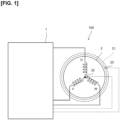
- Figure 1 is an explanatory diagram of a motor control system 100 of the present embodiment
- Fig. 2 is a configurational diagram of a motor control device 1.
- the motor control system 100 is provided with a motor control device 1 and a rotating electric machine (motor) 2.
- the motor control system 100 is installed in, e.g., an electric vehicle and used as a drive source for the electric vehicle.
- the motor control device 1 calculates, based on a torque command value T*, a rotational speed of the motor 2, and temperatures of windings, a command value for driving the motor 2; and outputs, based on the command value, electrical power to be fed to stator windings of the motor 2.
- the motor 2 is configured as a synchronous motor provided with windings of a plurality of phases (e.g., three phases of U-phase, V-phase, and W-phase).
- the motor 2 is provided with a water jacket 21, and is cooled by cooling water flowing through the water jacket 21.
- the motor 2 is provided with a winding temperature sensor 22 for detecting a winding temperature Tm of the motor 2, and a cooling water temperature sensor 23 for detecting a cooling water temperature Tw of the water jacket 21.
- the motor 2 may experience a "motor lock" state, in which an attempt is made to generate torque while rotation of the motor 2 is in a stopped or an extremely slow state.
- a motor lock state electrical current might concentrate in a winding of a specific phase, and heat generated by the winding will increase in amount.
- the motor 2 is provided with a winding temperature sensor 22 for detecting the winding temperature Tm; however, the winding temperature sensor 22 is not necessarily able to detect the highest temperature of the windings.
- the present embodiment is configured such that an estimate is made of a temperature in which deviation from the actual winding temperature is small, by using an offset value discussed further below.
- Figure 2 is a configurational block diagram of the motor control device 1.
- the motor control device 1 has a microcomputer provided with a CPU, a storage device, etc.
- the CPU executes a program recorded in the storage device, whereby functions of various units illustrated in Fig. 2 are realized.
- the motor control device 1 is provided with a low-rotation region assessment unit 3, a winding temperature estimation unit 4, a restriction ratio computation unit 5, a torque command value computation unit 6, a torque control unit 7, a dq axis-UVW phase conversion unit 8, a PWM conversion unit 9, a UVW phase-dq axis conversion unit 13, and a rotational speed computation unit 15 as a configuration for mainly performing computations.
- the motor control device 1 is provided with a battery 10 and an inverter 11 as a configuration mainly relating to feeding electrical power to the motor 2.
- the motor control device 1 is provided with a voltage sensor 10V, an electrical power sensor 12, a rotor position sensor 14, a winding temperature sensor 22, and a cooling water temperature sensor 23, as various types of sensors.
- the low-rotation region assessment unit 3 assesses whether the motor 2 is in a low-rotation region or a high-rotation region based on the rotational speed of the motor 2. More specifically, the low-rotation region assessment unit 3 acquires a value N detected for the rotational speed of the motor 2 calculated by the rotational speed computation unit 15, compares the acquired rotational speed detection value N and an assessment threshold, and assesses whether the motor 2 is currently in a low-rotation region or a high-rotation region.
- the assessment threshold is set to a value with which it is possible to assess whether the motor 2 is in a lock state, e.g., a value of zero to several tens of revolutions per minute.
- the winding temperature estimation unit 4 calculates an estimated maximum temperature T est of the windings of the motor 2.
- the estimated maximum temperature T est is an estimated value for a maximum temperature of a winding that is the highest from among the plurality of windings, and is computationally obtained so as to be a higher value than the actual maximum temperature of the windings.
- the winding temperature estimation unit 4 calculates, based on a d-axis electrical current estimation value i d_est , a q-axis electrical current estimation value i q_est , the rotational speed detection value N, the winding temperature Tm, and the cooling water temperature Tw, the estimated maximum temperature T est , which is an estimated value for the highest temperature of the windings reached, and outputs the estimated maximum temperature T est to the restriction ratio computation unit 5. Details of the operation of the winding temperature estimation unit 4 will be discussed further below with reference to Fig. 3 .
- the restriction ratio computation unit 5 calculates, based on the estimated maximum temperature T est , a torque restriction ratio R lim used for restricting a drive torque of the motor 2.
- the restriction ratio computation unit 5 calculates the torque restriction ratio R lim , with reference to the graph illustrated in Fig. 4 , according to the estimated maximum temperature T est estimated by the winding temperature estimation unit 4.
- the torque restriction ratio R lim is a command value (percentage) that determines how much the torque is to be restricted with respect to the torque command value T*, and is a value that varies from no restriction (R100: 100%) to a maximum adjustment rate (R min : e.g., 50%) according to the value of the estimated maximum temperature T est calculated by the winding temperature estimation unit 4.
- Figure 4 is a graph used for calculating the torque restriction ratio R lim , and is stored in advance in the restriction ratio computation unit 5.
- the torque restriction ratio R lim is set so as to vary between a torque restriction lower limit value R min , which is the largest restriction ratio for suppressing insulation degradation caused by a winding being at a high temperature, and R 100 at which the torque is not restricted, according to the estimated maximum temperature T est .
- a temperature threshold T 100 is the highest winding temperature at which the temperature of the windings does not cause insulation degradation
- a temperature threshold T min is the lowest winding temperature at which insulation degradation can be suppressed by performing a restriction using the torque restriction lower limit value R min , even if the estimated maximum temperature T est increases.
- the torque command value computation unit 6 illustrated in Fig. 2 calculates a final torque command value T* fin , which is the torque with which the motor 2 is actually driven, based on the torque command value T* supported by a higher system.
- the torque command value T*, the torque restriction ratio R lim computationally obtained by the restriction ratio computation unit 5, and a result of the assessment by the low-rotation region assessment unit 3 are inputted into the torque command value computation unit 6. From these values, the torque command value computation unit 6 outputs, the torque command value T* as the final torque command value T *fin without modification to the torque control unit 7 if it is assessed that the motor 2 is in a high-rotation region.
- the torque command value computation unit 6 calculates, as the final torque command value T* fin , a value obtained by multiplying the torque command value T* by the torque restriction ratio R lim , and outputs the calculated final torque command value T* fin to the torque control unit 7.
- the torque command value computation unit 6 executes, in a motor lock state, a control step of multiplying the torque command value T* by the torque restriction ratio R lim calculated based on the winding temperature Tm and the offset value and thereby restricting the torque command value T*, and controlling the input electrical power inputted into the motor 2.
- the torque command value computation unit 6 constitutes a control unit.
- the torque control unit 7 calculates, according to the final torque command value T* fin , a battery voltage detection value V dc , the rotational speed detection value N, a d-axis electrical current value i d , and a q-axis electrical current value i q , a d-axis voltage command value V* d and a q-axis voltage command value V* q .
- the torque control unit 7 outputs these calculated voltage command values to the dq axis-UVW phase conversion unit 8.
- the dq axis-UVW phase conversion unit 8 converts the d-axis voltage command value V* d and the q-axis voltage command value V* q to UVW-phase voltage command values V* u , V* v , V* w and outputs the UVW-phase voltage command values V* u , V* v , V* w to the PWM conversion unit 9.
- the PWM conversion unit 9 outputs, based on the UVW-phase voltage command values V* u , V* v , V* w , command values (D* uu , D* ul , D* vu , D* vl , D* wu , D* wl ) for the inverter 11.
- the inverter 11 is made of a three-phase power semiconductor, and converts, based on the command values outputted from the PWM conversion unit 9, DC electrical power fed from the battery 10 into three-phase AC electrical power and feeds the three-phase AC electrical power to the motor 2.
- the motor 2 is driven by the three-phase AC electrical power fed from the inverter 11.
- Current sensors 12 are provided to an output-side terminal of the inverter 11, and detect current values iu, iv of at least two phases of the three-phase electrical power.
- a rotor position sensor 14 is provided to the motor 2 and detects an electrical angle detection value ⁇ for the motor 2.
- the detected current values i u , i v and the electrical angle detection value ⁇ are inputted into the UVW phase-dq axis conversion unit 13.
- the UVW phase-dq axis conversion unit 13 performs a conversion from the inputted values to dq-axes-current values i d , i q and outputs the result to the torque control unit 7.
- the electrical angle detection value ⁇ outputted from the rotor position sensor 14 of the motor 2 is converted into a rotational speed detection value N for the motor 2 by the rotational speed computation unit 15, and outputted to the low-rotation region assessment unit 3 and the torque control unit 7.
- the rotor position sensor 14 is constituted by e.g., a Hall sensor.
- the winding temperature sensor 22 of the motor 2 detects the winding temperature Tm of the motor 2.
- the winding temperature Tm is a value that varies according to electrical currents flowing for each of the phases.
- the winding temperature sensor 22 is disposed at a position, at a coil end, corresponding to a neutral point to which the respective phases formed by the windings are connected to each other, as discussed further below with reference to Fig. 9.
- a value detected by the winding temperature sensor 22 is outputted as the winding temperature Tm.
- the cooling water temperature sensor 23 is provided to the water jacket 21 of the motor 2 and detects the cooling water temperature Tw of the cooling water flowing through the water jacket 21.
- the winding temperature sensor 22 and the cooling water temperature sensor 23 are configured from, e.g., a thermistor.
- FIG. 3 illustrates details of the winding temperature estimation unit 4.
- the winding temperature estimation unit 4 is provided with a current vector norm computation unit 41, a loss computation unit 42, a temperature computation unit 43, an adder 44, and a corrected temperature computation unit 45.
- the current vector norm computation unit 41 acquires the d-axis electrical current estimation value i d_est and the q-axis electrical current estimation value i q_est used for computation in the torque control unit 7, and calculates, based on the d-axis electrical current estimation value i d_est and the q-axis electrical current estimation value i q_est , a current vector norm value Ia 2 , which is a value indicating a total current inputted into the motor 2.
- the current vector norm value I a 2 is calculated from a product of the d-axis electrical current estimation value i d_est and the q-axis electrical current estimation value i q_est .
- the current vector norm computation unit 41 may acquire, instead of the d-axis electrical current estimation value i d_est and the q-axis electrical current estimation value i q_est , the d-axis current value i d and the q-axis current value i q , which are current values actually inputted into the motor 2, from the UVW phase-dq axis conversion unit 13.
- a total electrical power inputted into the motor 2 may be estimated, based on the torque command value T*.
- the loss computation unit 42 multiplies the current vector norm value I a 2 and a heat resistance R loss of the motor 2 and thereby calculates electrical power loss P loss .
- the heat resistance R loss is a value indicating a heat resistance of the motor 2 as a whole, and is a value obtained in advance according to a structure of the windings, etc., of the motor 2.
- the electrical power loss P loss of the motor 2 as a whole is calculated by multiplying the current vector norm value I a 2 indicating the current value flowing through the motor 2 by the heat resistance R loss .
- the temperature computation unit 43 calculates, from the electrical power loss P loss , an estimated temperature change ⁇ T est , which is the largest temperature increase in the windings of three phases of the motor 2, using a transfer function G(s).
- the transfer function G(s) is a transfer function having a dynamic characteristic of at least the first order or higher, and is a function set in advance according to the structure of the windings, etc., of the motor 2.
- the adder 44 adds the estimated temperature change ⁇ T est and a corrected winding temperature Tm' calculated by the corrected temperature computation unit 45, and thereby calculates the estimated maximum temperature T est of the winding, from among the windings of a plurality of phases in the motor 2, in which the temperature becomes the highest.
- the corrected temperature computation unit 45 calculates the corrected winding temperature Tm' based on the winding temperature Tm acquired by the winding temperature sensor 22, the cooling water temperature Tw acquired by the cooling water temperature sensor 23, and the result of the assessment by the low-rotation region assessment unit 3.
- the calculated corrected winding temperature Tm' is outputted to the adder 44.
- the estimated maximum temperature T est is calculated according to the winding temperature Tm and the current vector norm value I a 2 , which is a value indicating the total electrical current inputted into the motor 2, whereby an estimation step is executed.
- the winding temperature estimation unit 4 constitutes an estimation unit.
- the corrected temperature computation unit 45 references a graph of offset values (see Fig. 5 ) stored in advance, and acquires an offset value corresponding to the winding temperature Tm acquired from the winding temperature sensor 22 and the cooling water temperature Tw acquired from the cooling water temperature sensor 23.
- the corrected temperature computation unit 45 adds the offset value obtained from the graph to the winding temperature Tm for when there is a motor lock state, and thereby calculates the corrected winding temperature Tm'.
- the corrected temperature computation unit 45 calculates an offset value according to the winding temperature Tm and the cooling water temperature Tw and adds the offset value to the winding temperature Tm to calculate the corrected winding temperature Tm', and the adder 44 calculates the estimated maximum temperature T est based on the corrected winding temperature Tm', whereby a correction step is executed.
- the corrected temperature computation unit 45 and the adder 44 constitute a correction unit.
- Fig. 5 is an example of a graph of offset values, stored in advance by the corrected temperature computation unit 45.
- This graph records offset values, which are values indicating a size of deviation between the highest actual winding temperature of the windings reached and the winding temperature Tm acquired by the winding temperature sensor 22, with respect to difference values between the winding temperature Tm and the cooling water temperature Tw.
- the winding temperature sensor 22 is not necessarily provided at a position in the motor 2 that reaches the highest temperature, and also detects a temperature lower than the actual winding temperature due to heat transfer between the winding surfaces and the sensor or a response delay in the sensor, etc.
- the corrected winding temperature Tm' obtained by adding the offset value to the winding temperature Tm can be a value for which deviation from the actual winding temperature is small.
- the values depicted in the graph illustrated in Fig. 5 vary according to the structure of the windings of the motor 2, a heat transfer coefficient with respect to heat transfer with the cooling water, or a position of the winding temperature sensor 22, etc., and is obtained in advance by experimentation, etc.
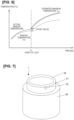
- Figure 6 is a time chart illustrating a relationship between the winding temperature Tm and the estimated maximum temperature T est .
- the winding temperature Tm acquired by the winding temperature sensor 22 is detected as a value smaller than the actual winding temperature.
- the motor 2 enters a motor lock state at timing T1 in Fig. 6 .
- the corrected temperature computation unit 45 calculates the corrected winding temperature Tm', which is a value obtained by adding the offset value illustrated in Fig. 5 .
- the initial value of the estimated temperature change ⁇ T est calculated from the d-axis electrical current estimation value i d_est and the q-axis electrical current estimation value i q_est is zero; therefore, the initial value of the estimated maximum temperature T est when a motor lock state occurs is the corrected winding temperature Tm', which is the value obtained by adding the offset value to the winding temperature Tm.
- the initial value of the estimated maximum temperature T est thus calculated is a value higher than the actual winding temperature of the motor 2, and the difference with respect to the actual winding temperature is small.
- the estimated maximum temperature T est subsequently changes as the estimated temperature change ⁇ T est changes.
- the estimated maximum temperature T est is calculated by adding the estimated temperature change ⁇ T est to the corrected winding temperature Tm' for when a motor lock state occurred; therefore, the value would be higher than the actual winding temperature of the motor 2, and the difference with respect to the actual winding temperature would be smaller.
- Figure 7 is an explanatory diagram illustrating the disposition of the winding temperature sensor 22.
- the winding temperature sensor 22 is fixed to a distal end part of a coil end 52 formed by folding back windings 51 at an axial-direction-end part of a stator core 50 constituting the motor 2, the windings 51 being wound around the stator core 50.
- the windings 51 of the present embodiment are constituted from a rectangular wire, and are folded back at the coil end 52 at one end part of the stator core 50 and connected (welded) according to the respective phase at the coil end 52 at the other end part.
- the winding temperature sensor 22 is positioned, at the distal end part of one of the coil ends 52, so as to be in contact with one of the windings 51.
- the winding temperature sensor 22 is fixed to a neutral point bus bar connected to each of the windings 51 comprising the U-phase, V-phase, and W-phase, at a coil end 52.
- the winding temperature sensor 22 is able to measure temperature regardless of which of the windings of the three phases an electrical current flows between.
- the winding temperature sensor 22 may be directly fixed to a winding 51 by means of a bolt or an adhesive, etc.
- the winding temperature sensor 22 is fixed to a component disposed around the windings 51 (e.g., a bracket covering a coil end from a circumferential direction), and the component is attached to the coil end, whereby a winding 51 and the winding temperature sensor 22 are put in intimate contact.
- the present embodiment described above is a method for controlling a motor 2 provided with windings of a plurality of phases and a water jacket 21 serving as a channel for cooling water.
- the motor 2 is provided with the winding temperature sensor 22 serving as a winding temperature detection unit for detecting the temperature of the windings, the cooling water temperature sensor 23 serving as a cooling water temperature detection unit for detecting the temperature of the cooling water, the rotational speed computation unit 15 serving as a rotation detection unit for detecting rotation of the motor 2, and the current vector norm computation unit 41 serving as an input electrical power estimation unit for estimating input electrical power inputted into the motor 2.
- the control method is provided with: an estimation step for calculating, when the motor 2 is in a lock state, the estimated maximum temperature T est of the winding of the phase in which the temperature becomes the highest from among the windings of a plurality of phases, based on the input electrical power; a correction step for calculating an offset value based on the winding temperature Tm and the cooling water temperature Tw and correcting the estimated maximum temperature T est based on the winding temperature Tm and the offset value; and a control step for controlling the input electrical power according to the estimated maximum temperature T est .
- an offset value is calculated based on the winding temperature Tm and the cooling water temperature Tw, and an estimated maximum temperature T est calculated based on the winding temperature Tm and the offset value is calculated.
- the offset value is a value indicating the size of deviation between the actual winding temperature and the winding temperature Tm acquired by the winding temperature sensor 22, and the estimated maximum temperature T est is calculated so that the deviation with respect to the actual winding temperature is small. Controlling the input electrical power for the motor 2 based on the estimated maximum temperature Test causes fewer restrictions to be applied on the output of the motor 2 in response to the torque command value T* for the motor 2, while suppressing the amount of heat generated by the windings.
- an offset value corresponding to a difference value between the winding temperature Tm and the cooling water temperature Tw is calculated, making it possible to calculate an estimated maximum temperature T est for which the actual winding temperature and the winding temperature Tm acquired by the winding temperature sensor 22 do not appreciably deviate.
- the offset value is a positive value corresponding to the difference value. Therefore, for the estimated maximum temperature T est , it is possible to estimate a temperature having a higher value than the actual winding temperature and that does not deviate from the actual winding temperature.
- the estimated maximum temperature T est is estimated based on an electrical current value inputted into the windings of a plurality of phases, making it possible to calculate a temperature approximating the actual winding temperature.
- the winding temperature sensor 22 is provided, in the stator core 50, at an axial end part of a coil end 52 formed by the windings 51, and is therefore able to detect the winding temperature of any of the three phases of the motor 2.
- the windings are constituted from rectangular wires; therefore, it becomes easier to determine the transfer function G(s) based on the electrical power loss P loss of the windings, and easier to estimate the estimated maximum temperature T est .
- the motor control system 100 of the present embodiment described above is not limited to use as a drive source for an electric vehicle, and may be used as a variety of drive sources other than for vehicles.
Landscapes
- Engineering & Computer Science (AREA)
- Power Engineering (AREA)
- Microelectronics & Electronic Packaging (AREA)
- Control Of Ac Motors In General (AREA)
- Control Of Electric Motors In General (AREA)
- Control Of Motors That Do Not Use Commutators (AREA)
Abstract
Description
- The present invention relates to a method for controlling a motor and a device for controlling a motor.
- A rotating electric machine (motor) has a plurality of phases U, V, and W, and is provided with windings corresponding to each of the phases. The motor rotates by having an electrical current fed to the windings of each of the phases. The windings produce heat due to channeling the electrical current.
- In a "motor lock" state, in which an attempt is made to generate torque while the motor is stopped or rotating extremely slowly, electrical current might concentrate in a winding of a specific phase (e.g., the U-phase), and heat generated by the winding will increase in amount. A very large amount of heat generated by a winding could degrade an insulation member of the winding, and it is therefore necessary to perform control so as to avoid such instances.
-
JP2012-228131A - In a case in which control is performed upon acquiring a coil temperature as with the prior art, depending on how a sensor for acquiring the coil temperature is arranged, it may not be possible to detect a temperature of a winding of a phase in which an amount of heat generated is the greatest; therefore, control may be impossible to perform in an appropriate manner.
- In view of such a problem, the purpose of the present invention is to provide a method for controlling a motor with which it is possible to suppress the amount of heat generated by windings in a motor lock state.
- One aspect of the present invention is applied to a method for controlling a motor provided with windings of a plurality of phases and a cooling water channel. The motor is provided with a winding temperature detection unit for detecting a temperature of the windings, a cooling water temperature detection unit for detecting a temperature of cooling water, a rotation detection unit for detecting rotation of the motor, and an input electrical power estimation unit for estimating input electrical power inputted into the motor. The control method is provided with: an estimation step for calculating, when the motor is in a lock state, an estimated maximum temperature of a winding of a phase that reaches a highest temperature from among the windings of a plurality of phases, based on the input electrical power; a correction step for calculating an offset value based on the detected temperature of the windings and the detected temperature of the cooling water, and correcting the estimated maximum temperature for correction based on the temperature of the windings and the offset value; and a control step for controlling the input electrical power according to the corrected estimated maximum temperature.
- According to the present invention, an offset value is calculated based on a temperature of windings and a temperature of cooling water, and an estimated maximum temperature of a winding is corrected with the offset value, therefore making it possible to control an input electrical power of a motor using a temperature value for which there is little deviation from an actual winding temperature. As a result, fewer restrictions are applied on a torque command for a motor, while an amount of heat generated by the windings is suppressed, even in a motor lock state.
-
-
Figure 1 is an explanatory diagram of a motor control system according to an embodiment of the present invention. -
Figure 2 is a configuration diagram of a motor control device. -
Figure 3 is a detailed configurational diagram of a winding temperature estimation unit -
Figure 4 is an explanatory diagram for a torque restriction ratio. -
Figure 5 is an explanatory diagram for an offset value. -
Figure 6 is an explanatory diagram for an estimated maximum temperature during motor lock. -
Figure 7 is a configurational view of a motor. - A preferred embodiment of the present invention will now be described.
-
Figure 1 is an explanatory diagram of amotor control system 100 of the present embodiment, andFig. 2 is a configurational diagram of amotor control device 1. - The
motor control system 100 is provided with amotor control device 1 and a rotating electric machine (motor) 2. Themotor control system 100 is installed in, e.g., an electric vehicle and used as a drive source for the electric vehicle. - The motor control device 1: calculates, based on a torque command value T*, a rotational speed of the
motor 2, and temperatures of windings, a command value for driving themotor 2; and outputs, based on the command value, electrical power to be fed to stator windings of themotor 2. - The
motor 2 is configured as a synchronous motor provided with windings of a plurality of phases (e.g., three phases of U-phase, V-phase, and W-phase). Themotor 2 is provided with awater jacket 21, and is cooled by cooling water flowing through thewater jacket 21. Themotor 2 is provided with awinding temperature sensor 22 for detecting a winding temperature Tm of themotor 2, and a coolingwater temperature sensor 23 for detecting a cooling water temperature Tw of thewater jacket 21. - The
motor 2 may experience a "motor lock" state, in which an attempt is made to generate torque while rotation of themotor 2 is in a stopped or an extremely slow state. In a motor lock state, electrical current might concentrate in a winding of a specific phase, and heat generated by the winding will increase in amount. - A very large amount of heat generated by a winding could degrade an insulation member of the winding. Therefore, it is necessary, when the winding temperature becomes high, to restrict electrical current fed to the
motor 2. - On the other hand, there is a problem of it being difficult to detect an actual winding temperature. As discussed above, the
motor 2 is provided with awinding temperature sensor 22 for detecting the winding temperature Tm; however, thewinding temperature sensor 22 is not necessarily able to detect the highest temperature of the windings. - In response, it is possible to perform control based on a temperature value obtained by providing a sufficient margin to the detected winding temperature Tm in anticipation of the temperature of the windings increasing. However, if control is performed in such a manner, a restriction on electrical current may be imposed even when a load on the
motor 2 is small and the actual winding temperature is low, resulting in a possibility of themotor 2 failing to satisfy the required torque, affecting drivability. - As a result, it has not necessarily been possible in the past to appropriately control the
motor 2 based on the temperature of the windings. - As a result of a creative approach to the problem discussed above, the present embodiment is configured such that an estimate is made of a temperature in which deviation from the actual winding temperature is small, by using an offset value discussed further below.
-
Figure 2 is a configurational block diagram of themotor control device 1. - The
motor control device 1 has a microcomputer provided with a CPU, a storage device, etc. The CPU executes a program recorded in the storage device, whereby functions of various units illustrated inFig. 2 are realized. - It is possible to house the
motor control device 1 illustrated inFig. 2 in a same casing, and it is also possible for abattery 10 and aninverter 11 discussed further below to be housed in difference casings, with an electrical connection established therebetween by a harness, etc. - The
motor control device 1 is provided with a low-rotationregion assessment unit 3, a windingtemperature estimation unit 4, a restriction ratio computation unit 5, a torque command value computation unit 6, a torque control unit 7, a dq axis-UVWphase conversion unit 8, aPWM conversion unit 9, a UVW phase-dqaxis conversion unit 13, and a rotationalspeed computation unit 15 as a configuration for mainly performing computations. Themotor control device 1 is provided with abattery 10 and aninverter 11 as a configuration mainly relating to feeding electrical power to themotor 2. Themotor control device 1 is provided with avoltage sensor 10V, anelectrical power sensor 12, arotor position sensor 14, awinding temperature sensor 22, and a coolingwater temperature sensor 23, as various types of sensors. - The low-rotation
region assessment unit 3 assesses whether themotor 2 is in a low-rotation region or a high-rotation region based on the rotational speed of themotor 2. More specifically, the low-rotationregion assessment unit 3 acquires a value N detected for the rotational speed of themotor 2 calculated by the rotationalspeed computation unit 15, compares the acquired rotational speed detection value N and an assessment threshold, and assesses whether themotor 2 is currently in a low-rotation region or a high-rotation region. The assessment threshold is set to a value with which it is possible to assess whether themotor 2 is in a lock state, e.g., a value of zero to several tens of revolutions per minute. - The winding
temperature estimation unit 4 calculates an estimated maximum temperature Test of the windings of themotor 2. The estimated maximum temperature Test is an estimated value for a maximum temperature of a winding that is the highest from among the plurality of windings, and is computationally obtained so as to be a higher value than the actual maximum temperature of the windings. - The winding
temperature estimation unit 4 calculates, based on a d-axis electrical current estimation value id_est, a q-axis electrical current estimation value iq_est, the rotational speed detection value N, the winding temperature Tm, and the cooling water temperature Tw, the estimated maximum temperature Test, which is an estimated value for the highest temperature of the windings reached, and outputs the estimated maximum temperature Test to the restriction ratio computation unit 5. Details of the operation of the windingtemperature estimation unit 4 will be discussed further below with reference toFig. 3 . - The restriction ratio computation unit 5 calculates, based on the estimated maximum temperature Test, a torque restriction ratio Rlim used for restricting a drive torque of the
motor 2. - The restriction ratio computation unit 5 calculates the torque restriction ratio Rlim, with reference to the graph illustrated in
Fig. 4 , according to the estimated maximum temperature Test estimated by the windingtemperature estimation unit 4. The torque restriction ratio Rlim is a command value (percentage) that determines how much the torque is to be restricted with respect to the torque command value T*, and is a value that varies from no restriction (R100: 100%) to a maximum adjustment rate (Rmin: e.g., 50%) according to the value of the estimated maximum temperature Test calculated by the windingtemperature estimation unit 4. -
Figure 4 is a graph used for calculating the torque restriction ratio Rlim, and is stored in advance in the restriction ratio computation unit 5. - In the graph illustrated in
Fig. 4 , the torque restriction ratio Rlim is set so as to vary between a torque restriction lower limit value Rmin, which is the largest restriction ratio for suppressing insulation degradation caused by a winding being at a high temperature, and R100 at which the torque is not restricted, according to the estimated maximum temperature Test. - A temperature threshold T100 is the highest winding temperature at which the temperature of the windings does not cause insulation degradation, and a temperature threshold Tmin is the lowest winding temperature at which insulation degradation can be suppressed by performing a restriction using the torque restriction lower limit value Rmin, even if the estimated maximum temperature Test increases.
- Therefore, when, in a motor lock state, the estimated maximum temperature Test is exceeding the temperature threshold T100, the torque command value T* is multiplied by the torque restriction lower limit value Rmin calculated based on the above graph, whereby the electrical current flowing through the
motor 2 is restricted. - The torque command value computation unit 6 illustrated in
Fig. 2 calculates a final torque command value T*fin, which is the torque with which themotor 2 is actually driven, based on the torque command value T* supported by a higher system. - The torque command value T*, the torque restriction ratio Rlim computationally obtained by the restriction ratio computation unit 5, and a result of the assessment by the low-rotation
region assessment unit 3 are inputted into the torque command value computation unit 6. From these values, the torque command value computation unit 6 outputs, the torque command value T* as the final torque command value T*fin without modification to the torque control unit 7 if it is assessed that themotor 2 is in a high-rotation region. If it is assessed that themotor 2 is in a low-rotation region, i.e., in a motor lock state, the torque command value computation unit 6 calculates, as the final torque command value T*fin, a value obtained by multiplying the torque command value T* by the torque restriction ratio Rlim, and outputs the calculated final torque command value T*fin to the torque control unit 7. - Thus, the torque command value computation unit 6 executes, in a motor lock state, a control step of multiplying the torque command value T* by the torque restriction ratio Rlim calculated based on the winding temperature Tm and the offset value and thereby restricting the torque command value T*, and controlling the input electrical power inputted into the
motor 2. In other words, the torque command value computation unit 6 constitutes a control unit. - The torque control unit 7 calculates, according to the final torque command value T*fin, a battery voltage detection value Vdc, the rotational speed detection value N, a d-axis electrical current value id, and a q-axis electrical current value iq, a d-axis voltage command value V*d and a q-axis voltage command value V*q. The torque control unit 7 outputs these calculated voltage command values to the dq axis-UVW
phase conversion unit 8. - The dq axis-UVW
phase conversion unit 8 converts the d-axis voltage command value V*d and the q-axis voltage command value V*q to UVW-phase voltage command values V*u, V*v, V*w and outputs the UVW-phase voltage command values V*u, V*v, V*w to thePWM conversion unit 9. - The
PWM conversion unit 9 outputs, based on the UVW-phase voltage command values V*u, V*v, V*w, command values (D*uu, D*ul, D*vu, D*vl, D*wu, D*wl) for theinverter 11. - The
inverter 11 is made of a three-phase power semiconductor, and converts, based on the command values outputted from thePWM conversion unit 9, DC electrical power fed from thebattery 10 into three-phase AC electrical power and feeds the three-phase AC electrical power to themotor 2. Themotor 2 is driven by the three-phase AC electrical power fed from theinverter 11. -
Current sensors 12 are provided to an output-side terminal of theinverter 11, and detect current values iu, iv of at least two phases of the three-phase electrical power. Arotor position sensor 14 is provided to themotor 2 and detects an electrical angle detection value θ for themotor 2. The detected current values iu, iv and the electrical angle detection value θ are inputted into the UVW phase-dqaxis conversion unit 13. The UVW phase-dqaxis conversion unit 13 performs a conversion from the inputted values to dq-axes-current values id, iq and outputs the result to the torque control unit 7. - The electrical angle detection value θ outputted from the
rotor position sensor 14 of themotor 2 is converted into a rotational speed detection value N for themotor 2 by the rotationalspeed computation unit 15, and outputted to the low-rotationregion assessment unit 3 and the torque control unit 7. Therotor position sensor 14 is constituted by e.g., a Hall sensor. - The winding
temperature sensor 22 of themotor 2 detects the winding temperature Tm of themotor 2. The winding temperature Tm is a value that varies according to electrical currents flowing for each of the phases. In the present embodiment, the windingtemperature sensor 22 is disposed at a position, at a coil end, corresponding to a neutral point to which the respective phases formed by the windings are connected to each other, as discussed further below with reference to Fig. 9. A value detected by the windingtemperature sensor 22 is outputted as the winding temperature Tm. - As illustrated in
Fig. 1 , the coolingwater temperature sensor 23 is provided to thewater jacket 21 of themotor 2 and detects the cooling water temperature Tw of the cooling water flowing through thewater jacket 21. The windingtemperature sensor 22 and the coolingwater temperature sensor 23 are configured from, e.g., a thermistor. -
Figure 3 illustrates details of the windingtemperature estimation unit 4. - The winding
temperature estimation unit 4 is provided with a current vectornorm computation unit 41, aloss computation unit 42, atemperature computation unit 43, anadder 44, and a correctedtemperature computation unit 45. - The current vector
norm computation unit 41 acquires the d-axis electrical current estimation value id_est and the q-axis electrical current estimation value iq_est used for computation in the torque control unit 7, and calculates, based on the d-axis electrical current estimation value id_est and the q-axis electrical current estimation value iq_est, a current vector norm value Ia2, which is a value indicating a total current inputted into themotor 2. The current vector norm value Ia 2 is calculated from a product of the d-axis electrical current estimation value id_est and the q-axis electrical current estimation value iq_est. - The current vector
norm computation unit 41 may acquire, instead of the d-axis electrical current estimation value id_est and the q-axis electrical current estimation value iq_est, the d-axis current value id and the q-axis current value iq, which are current values actually inputted into themotor 2, from the UVW phase-dqaxis conversion unit 13. In addition, instead of current values, a total electrical power inputted into themotor 2 may be estimated, based on the torque command value T*. - The
loss computation unit 42 multiplies the current vector norm value Ia 2 and a heat resistance Rloss of themotor 2 and thereby calculates electrical power loss Ploss. The heat resistance Rloss is a value indicating a heat resistance of themotor 2 as a whole, and is a value obtained in advance according to a structure of the windings, etc., of themotor 2. The electrical power loss Ploss of themotor 2 as a whole is calculated by multiplying the current vector norm value Ia 2 indicating the current value flowing through themotor 2 by the heat resistance Rloss. - The
temperature computation unit 43 calculates, from the electrical power loss Ploss, an estimated temperature change ΔTest, which is the largest temperature increase in the windings of three phases of themotor 2, using a transfer function G(s). The transfer function G(s) is a transfer function having a dynamic characteristic of at least the first order or higher, and is a function set in advance according to the structure of the windings, etc., of themotor 2. - The
adder 44 adds the estimated temperature change ΔTest and a corrected winding temperature Tm' calculated by the correctedtemperature computation unit 45, and thereby calculates the estimated maximum temperature Test of the winding, from among the windings of a plurality of phases in themotor 2, in which the temperature becomes the highest. - The corrected
temperature computation unit 45 calculates the corrected winding temperature Tm' based on the winding temperature Tm acquired by the windingtemperature sensor 22, the cooling water temperature Tw acquired by the coolingwater temperature sensor 23, and the result of the assessment by the low-rotationregion assessment unit 3. The calculated corrected winding temperature Tm' is outputted to theadder 44. - Thus, in the winding
temperature estimation unit 4, the estimated maximum temperature Test is calculated according to the winding temperature Tm and the current vector norm value Ia 2, which is a value indicating the total electrical current inputted into themotor 2, whereby an estimation step is executed. The windingtemperature estimation unit 4 constitutes an estimation unit. - Next, a specific operation of the corrected
temperature computation unit 45 will be described. When there is a motor lock state in view of the result of the assessment by the low-rotationregion assessment unit 3, the correctedtemperature computation unit 45 references a graph of offset values (seeFig. 5 ) stored in advance, and acquires an offset value corresponding to the winding temperature Tm acquired from the windingtemperature sensor 22 and the cooling water temperature Tw acquired from the coolingwater temperature sensor 23. - The corrected
temperature computation unit 45 adds the offset value obtained from the graph to the winding temperature Tm for when there is a motor lock state, and thereby calculates the corrected winding temperature Tm'. - Thus, when there is a motor lock state, the corrected
temperature computation unit 45 calculates an offset value according to the winding temperature Tm and the cooling water temperature Tw and adds the offset value to the winding temperature Tm to calculate the corrected winding temperature Tm', and theadder 44 calculates the estimated maximum temperature Test based on the corrected winding temperature Tm', whereby a correction step is executed. The correctedtemperature computation unit 45 and theadder 44 constitute a correction unit. -
Fig. 5 is an example of a graph of offset values, stored in advance by the correctedtemperature computation unit 45. - This graph records offset values, which are values indicating a size of deviation between the highest actual winding temperature of the windings reached and the winding temperature Tm acquired by the winding
temperature sensor 22, with respect to difference values between the winding temperature Tm and the cooling water temperature Tw. - The winding
temperature sensor 22 is not necessarily provided at a position in themotor 2 that reaches the highest temperature, and also detects a temperature lower than the actual winding temperature due to heat transfer between the winding surfaces and the sensor or a response delay in the sensor, etc. In contrast, in the present embodiment, the corrected winding temperature Tm' obtained by adding the offset value to the winding temperature Tm can be a value for which deviation from the actual winding temperature is small. - The values depicted in the graph illustrated in
Fig. 5 vary according to the structure of the windings of themotor 2, a heat transfer coefficient with respect to heat transfer with the cooling water, or a position of the windingtemperature sensor 22, etc., and is obtained in advance by experimentation, etc. -
Figure 6 is a time chart illustrating a relationship between the winding temperature Tm and the estimated maximum temperature Test. - As discussed further above, the winding temperature Tm acquired by the winding
temperature sensor 22 is detected as a value smaller than the actual winding temperature. - Here, the
motor 2 enters a motor lock state at timing T1 inFig. 6 . When a motor lock state occurs, in the windingtemperature estimation unit 4, the correctedtemperature computation unit 45 calculates the corrected winding temperature Tm', which is a value obtained by adding the offset value illustrated inFig. 5 . - At this time, the initial value of the estimated temperature change ΔTest calculated from the d-axis electrical current estimation value id_est and the q-axis electrical current estimation value iq_est is zero; therefore, the initial value of the estimated maximum temperature Test when a motor lock state occurs is the corrected winding temperature Tm', which is the value obtained by adding the offset value to the winding temperature Tm.
- The initial value of the estimated maximum temperature Test thus calculated is a value higher than the actual winding temperature of the
motor 2, and the difference with respect to the actual winding temperature is small. - The estimated maximum temperature Test subsequently changes as the estimated temperature change ΔTest changes. As a result, the estimated maximum temperature Test is calculated by adding the estimated temperature change ΔTest to the corrected winding temperature Tm' for when a motor lock state occurred; therefore, the value would be higher than the actual winding temperature of the
motor 2, and the difference with respect to the actual winding temperature would be smaller. - Next, the disposition of the winding
temperature sensor 22 in the present embodiment will be described. -
Figure 7 is an explanatory diagram illustrating the disposition of the windingtemperature sensor 22. - The winding
temperature sensor 22 is fixed to a distal end part of acoil end 52 formed by folding backwindings 51 at an axial-direction-end part of astator core 50 constituting themotor 2, thewindings 51 being wound around thestator core 50. - The
windings 51 of the present embodiment are constituted from a rectangular wire, and are folded back at thecoil end 52 at one end part of thestator core 50 and connected (welded) according to the respective phase at thecoil end 52 at the other end part. - The winding
temperature sensor 22 is positioned, at the distal end part of one of the coil ends 52, so as to be in contact with one of thewindings 51. As an example, the windingtemperature sensor 22 is fixed to a neutral point bus bar connected to each of thewindings 51 comprising the U-phase, V-phase, and W-phase, at acoil end 52. - As a result, regardless of whether an electrical current flows between the U-phase winding and the V-phase winding, between the W-phase winding and the V-phase winding, or between the U-phase winding and the W-phase winding, an electrical current flows in the neutral point bus bar. As a result, the winding
temperature sensor 22 is able to measure temperature regardless of which of the windings of the three phases an electrical current flows between. - The winding
temperature sensor 22 may be directly fixed to a winding 51 by means of a bolt or an adhesive, etc. In an alternative configuration, the windingtemperature sensor 22 is fixed to a component disposed around the windings 51 (e.g., a bracket covering a coil end from a circumferential direction), and the component is attached to the coil end, whereby a winding 51 and the windingtemperature sensor 22 are put in intimate contact. - The present embodiment described above is a method for controlling a
motor 2 provided with windings of a plurality of phases and awater jacket 21 serving as a channel for cooling water. Themotor 2 is provided with the windingtemperature sensor 22 serving as a winding temperature detection unit for detecting the temperature of the windings, the coolingwater temperature sensor 23 serving as a cooling water temperature detection unit for detecting the temperature of the cooling water, the rotationalspeed computation unit 15 serving as a rotation detection unit for detecting rotation of themotor 2, and the current vectornorm computation unit 41 serving as an input electrical power estimation unit for estimating input electrical power inputted into themotor 2. The control method is provided with: an estimation step for calculating, when themotor 2 is in a lock state, the estimated maximum temperature Test of the winding of the phase in which the temperature becomes the highest from among the windings of a plurality of phases, based on the input electrical power; a correction step for calculating an offset value based on the winding temperature Tm and the cooling water temperature Tw and correcting the estimated maximum temperature Test based on the winding temperature Tm and the offset value; and a control step for controlling the input electrical power according to the estimated maximum temperature Test. - Thus, in the present embodiment, an offset value is calculated based on the winding temperature Tm and the cooling water temperature Tw, and an estimated maximum temperature Test calculated based on the winding temperature Tm and the offset value is calculated. The offset value is a value indicating the size of deviation between the actual winding temperature and the winding temperature Tm acquired by the winding
temperature sensor 22, and the estimated maximum temperature Test is calculated so that the deviation with respect to the actual winding temperature is small. Controlling the input electrical power for themotor 2 based on the estimated maximum temperature Test causes fewer restrictions to be applied on the output of themotor 2 in response to the torque command value T* for themotor 2, while suppressing the amount of heat generated by the windings. - In the present embodiment, in the correction step, an offset value corresponding to a difference value between the winding temperature Tm and the cooling water temperature Tw is calculated, making it possible to calculate an estimated maximum temperature Test for which the actual winding temperature and the winding temperature Tm acquired by the winding
temperature sensor 22 do not appreciably deviate. - In the present embodiment, the offset value is a positive value corresponding to the difference value. Therefore, for the estimated maximum temperature Test, it is possible to estimate a temperature having a higher value than the actual winding temperature and that does not deviate from the actual winding temperature.
- In the present embodiment, in the estimation step, the estimated maximum temperature Test is estimated based on an electrical current value inputted into the windings of a plurality of phases, making it possible to calculate a temperature approximating the actual winding temperature.
- In the present embodiment, the winding
temperature sensor 22 is provided, in thestator core 50, at an axial end part of acoil end 52 formed by thewindings 51, and is therefore able to detect the winding temperature of any of the three phases of themotor 2. - In the present embodiment, the windings are constituted from rectangular wires; therefore, it becomes easier to determine the transfer function G(s) based on the electrical power loss Ploss of the windings, and easier to estimate the estimated maximum temperature Test.
- A description has been given for an embodiment of the present invention, but the above embodiment merely indicates an example of application of the present invention, and the technical scope of the present invention is not intended to be limited to the specific configuration of the above embodiment.
- The
motor control system 100 of the present embodiment described above is not limited to use as a drive source for an electric vehicle, and may be used as a variety of drive sources other than for vehicles.
Claims (7)
- A method for controlling a motor having windings of a plurality of phases and a channel for cooling water,the motor having a winding temperature detection unit that detects a temperature of the windings, a cooling water temperature detection unit that detects a temperature of the cooling water, a rotation detection unit that detects rotation of the motor, and an input electrical power estimation unit that estimates input electrical power inputted into the motor,the motor control method comprising:an estimation step for calculating an estimated maximum temperature of the winding of the phase that reaches a highest temperature from among the windings of the plurality of phases based on the input electrical power when the motor is in a lock state;a correction step for calculating an offset value based on a detected temperature of the windings and a detected temperature of the cooling water, and correcting the estimated maximum temperature based on the temperature of the windings and the offset value; anda control step for controlling the input electrical power according to the estimated maximum temperature.
- The method for controlling a motor according to claim 1, wherein
the offset value is calculated in the correction step according to a difference value between a temperature of the motor and the temperature of the cooling water. - The method for controlling a motor according to claim 2, wherein
the offset value is a positive value corresponding to the difference value. - The method for controlling a motor according to any of claims 1-3, wherein
the estimated maximum temperature in the estimation step is estimated based on an electrical current value inputted into the windings of the plurality of phases. - The method for controlling a motor according to any of claims 1-4, wherein
the winding temperature detection unit is provided at an axial end part of a coil end formed by the windings. - The method for controlling a motor according to any of claims 1-5, wherein
the windings are formed from a rectangular wire. - A device for controlling a motor provided with windings of a plurality of phases and a channel for cooling water,the motor having a winding temperature detection unit that detects a temperature of the windings, a cooling water temperature detection unit that detects a temperature of the cooling water, a rotation detection unit that detects rotation of the motor, and an input electrical power estimation unit that estimates input electrical power inputted into the motor,the motor control device comprising:an estimation unit for calculating an estimated maximum temperature of the winding of the phase that reaches a highest temperature from among the windings of the plurality of phases based on the input electrical power when the motor is in a lock state;a correction unit for calculating an offset value based on a detected temperature of the windings and a detected temperature of the cooling water, and correcting the estimated maximum temperature based on the temperature of the windings and the offset value; anda control unit for controlling the input electrical power according to the estimated maximum temperature.
Applications Claiming Priority (1)
| Application Number | Priority Date | Filing Date | Title |
|---|---|---|---|
| PCT/JP2021/018691 WO2022244084A1 (en) | 2021-05-17 | 2021-05-17 | Method for controlling motor and device for controlling motor |
Publications (3)
| Publication Number | Publication Date |
|---|---|
| EP4344053A1 true EP4344053A1 (en) | 2024-03-27 |
| EP4344053A4 EP4344053A4 (en) | 2024-08-07 |
| EP4344053B1 EP4344053B1 (en) | 2025-08-20 |
Family
ID=84141315
Family Applications (1)
| Application Number | Title | Priority Date | Filing Date |
|---|---|---|---|
| EP21847919.4A Active EP4344053B1 (en) | 2021-05-17 | 2021-05-17 | Method for controlling motor and device for controlling motor |
Country Status (7)
| Country | Link |
|---|---|
| US (1) | US12021472B2 (en) |
| EP (1) | EP4344053B1 (en) |
| JP (1) | JP7180793B1 (en) |
| CN (1) | CN116897507A (en) |
| BR (1) | BR112022001992A2 (en) |
| MX (1) | MX2022001398A (en) |
| WO (1) | WO2022244084A1 (en) |
Families Citing this family (1)
| Publication number | Priority date | Publication date | Assignee | Title |
|---|---|---|---|---|
| JP2024169155A (en) * | 2023-05-25 | 2024-12-05 | 株式会社デンソー | Motor control device and motor control program |
Family Cites Families (10)
| Publication number | Priority date | Publication date | Assignee | Title |
|---|---|---|---|---|
| JP3668666B2 (en) * | 2000-03-21 | 2005-07-06 | 株式会社日立製作所 | Synchronous motor, electric vehicle using the same, and control method thereof |
| JP3963175B2 (en) * | 2004-03-19 | 2007-08-22 | 日産自動車株式会社 | Temperature detection apparatus and temperature detection program |
| US7615951B2 (en) * | 2006-09-08 | 2009-11-10 | Gm Global Technology Operations, Inc. | Method and system for limiting the operating temperature of an electric motor |
| JP5332393B2 (en) * | 2008-08-19 | 2013-11-06 | トヨタ自動車株式会社 | Vehicle drive motor control device |
| US8421391B2 (en) * | 2010-05-12 | 2013-04-16 | GM Global Technology Operations LLC | Electric motor stator winding temperature estimation systems and methods |
| JP2012228131A (en) | 2011-04-22 | 2012-11-15 | Toyota Motor Corp | Drive control system for onboard rotary electric machine |
| JP6747244B2 (en) * | 2016-10-31 | 2020-08-26 | トヨタ自動車株式会社 | Rotating electric machine |
| KR102074111B1 (en) * | 2016-11-01 | 2020-02-05 | 닛산 지도우샤 가부시키가이샤 | Motor control method and motor control device |
| DE112020002714T5 (en) * | 2019-06-06 | 2022-02-17 | Nidec Corporation | STATOR UNIT AND MOTOR |
| CN112092630B (en) * | 2020-09-23 | 2022-08-12 | 北京车和家信息技术有限公司 | Motor over-temperature protection method and device, driving system and vehicle |
-
2020
- 2020-05-17 MX MX2022001398A patent/MX2022001398A/en unknown
-
2021
- 2021-05-17 WO PCT/JP2021/018691 patent/WO2022244084A1/en not_active Ceased
- 2021-05-17 JP JP2021566506A patent/JP7180793B1/en active Active
- 2021-05-17 US US17/632,248 patent/US12021472B2/en active Active
- 2021-05-17 BR BR112022001992A patent/BR112022001992A2/en unknown
- 2021-05-17 EP EP21847919.4A patent/EP4344053B1/en active Active
- 2021-05-17 CN CN202180004666.2A patent/CN116897507A/en active Pending
Also Published As
| Publication number | Publication date |
|---|---|
| US12021472B2 (en) | 2024-06-25 |
| US20230361713A1 (en) | 2023-11-09 |
| EP4344053A4 (en) | 2024-08-07 |
| JPWO2022244084A1 (en) | 2022-11-24 |
| MX2022001398A (en) | 2023-01-24 |
| EP4344053B1 (en) | 2025-08-20 |
| BR112022001992A2 (en) | 2023-11-28 |
| CN116897507A (en) | 2023-10-17 |
| WO2022244084A1 (en) | 2022-11-24 |
| JP7180793B1 (en) | 2022-11-30 |
Similar Documents
| Publication | Publication Date | Title |
|---|---|---|
| JP4654217B2 (en) | Field weakening control device for permanent magnet motor and electric power steering using the same | |
| KR101958120B1 (en) | Device and method for controlling electric motor | |
| JP5331208B2 (en) | Abnormality detection device for permanent magnet type synchronous motor | |
| JP4379702B2 (en) | Brushless motor control device | |
| CN101841290B (en) | Motor control unit and motor control unit for vehicle steering apparatus | |
| US9660560B2 (en) | Motor drive circuit and method of driving a motor | |
| US10404201B2 (en) | Rotary electric machine controller and electric power steering device using the same | |
| US9054626B2 (en) | Motor control apparatus | |
| EP3537601B1 (en) | Motor control method | |
| JP6555430B2 (en) | Electric power steering device | |
| US10526010B2 (en) | Electric power steering apparatus | |
| US11381186B2 (en) | Motor drive device, electric oil pump, and method for detecting failure of motor drive device | |
| CN107005181A (en) | Motor drive control apparatus | |
| US10243489B2 (en) | Rotary electric machine control apparatus and electric power steering apparatus using the same | |
| US9294018B2 (en) | Electric motor control device | |
| EP4344053B1 (en) | Method for controlling motor and device for controlling motor | |
| JP2021040424A (en) | Control method of winding field magnetic type rotary electric machine, and control device of winding field magnetic type rotary electric machine | |
| JP6949242B2 (en) | Control device for AC rotating electric machine | |
| WO2016092910A1 (en) | Control device and control method | |
| JP5194608B2 (en) | Rotating electrical machine control device | |
| EP3093985B1 (en) | Control device for electric motor | |
| JP2006304441A (en) | Synchronous motor control device | |
| US20250167707A1 (en) | Motor drive, motor system, and method for driving motor | |
| WO2025238690A1 (en) | Motor abnormality diagnosis method and motor abnormality diagnosis system | |
| JP2023081030A (en) | Motor control method and motor control device |
Legal Events
| Date | Code | Title | Description |
|---|---|---|---|
| STAA | Information on the status of an ep patent application or granted ep patent |
Free format text: STATUS: UNKNOWN |
|
| STAA | Information on the status of an ep patent application or granted ep patent |
Free format text: STATUS: THE INTERNATIONAL PUBLICATION HAS BEEN MADE |
|
| PUAI | Public reference made under article 153(3) epc to a published international application that has entered the european phase |
Free format text: ORIGINAL CODE: 0009012 |
|
| STAA | Information on the status of an ep patent application or granted ep patent |
Free format text: STATUS: REQUEST FOR EXAMINATION WAS MADE |
|
| 17P | Request for examination filed |
Effective date: 20220202 |
|
| AK | Designated contracting states |
Kind code of ref document: A1 Designated state(s): AL AT BE BG CH CY CZ DE DK EE ES FI FR GB GR HR HU IE IS IT LI LT LU LV MC MK MT NL NO PL PT RO RS SE SI SK SM TR |
|
| A4 | Supplementary search report drawn up and despatched |
Effective date: 20240710 |
|
| RIC1 | Information provided on ipc code assigned before grant |
Ipc: H02P 29/64 20160101AFI20240704BHEP |
|
| DAV | Request for validation of the european patent (deleted) | ||
| DAX | Request for extension of the european patent (deleted) | ||
| GRAP | Despatch of communication of intention to grant a patent |
Free format text: ORIGINAL CODE: EPIDOSNIGR1 |
|
| STAA | Information on the status of an ep patent application or granted ep patent |
Free format text: STATUS: GRANT OF PATENT IS INTENDED |
|
| INTG | Intention to grant announced |
Effective date: 20250411 |
|
| RIC1 | Information provided on ipc code assigned before grant |
Ipc: H02K 11/25 20160101ALI20250404BHEP Ipc: H02K 5/20 20060101ALI20250404BHEP Ipc: H02P 29/64 20160101AFI20250404BHEP |
|
| GRAS | Grant fee paid |
Free format text: ORIGINAL CODE: EPIDOSNIGR3 |
|
| GRAA | (expected) grant |
Free format text: ORIGINAL CODE: 0009210 |
|
| STAA | Information on the status of an ep patent application or granted ep patent |
Free format text: STATUS: THE PATENT HAS BEEN GRANTED |
|
| AK | Designated contracting states |
Kind code of ref document: B1 Designated state(s): AL AT BE BG CH CY CZ DE DK EE ES FI FR GB GR HR HU IE IS IT LI LT LU LV MC MK MT NL NO PL PT RO RS SE SI SK SM TR |
|
| REG | Reference to a national code |
Ref country code: GB Ref legal event code: FG4D |
|
| REG | Reference to a national code |
Ref country code: CH Ref legal event code: EP |
|
| REG | Reference to a national code |
Ref country code: IE Ref legal event code: FG4D |
|
| REG | Reference to a national code |
Ref country code: DE Ref legal event code: R096 Ref document number: 602021036843 Country of ref document: DE |
|
| REG | Reference to a national code |
Ref country code: NL Ref legal event code: MP Effective date: 20250820 |
|
| PG25 | Lapsed in a contracting state [announced via postgrant information from national office to epo] |
Ref country code: IS Free format text: LAPSE BECAUSE OF FAILURE TO SUBMIT A TRANSLATION OF THE DESCRIPTION OR TO PAY THE FEE WITHIN THE PRESCRIBED TIME-LIMIT Effective date: 20251220 |
|
| PG25 | Lapsed in a contracting state [announced via postgrant information from national office to epo] |
Ref country code: NO Free format text: LAPSE BECAUSE OF FAILURE TO SUBMIT A TRANSLATION OF THE DESCRIPTION OR TO PAY THE FEE WITHIN THE PRESCRIBED TIME-LIMIT Effective date: 20251120 |
|
| REG | Reference to a national code |
Ref country code: LT Ref legal event code: MG9D |
|
| PG25 | Lapsed in a contracting state [announced via postgrant information from national office to epo] |
Ref country code: PT Free format text: LAPSE BECAUSE OF FAILURE TO SUBMIT A TRANSLATION OF THE DESCRIPTION OR TO PAY THE FEE WITHIN THE PRESCRIBED TIME-LIMIT Effective date: 20251222 |
|
| PG25 | Lapsed in a contracting state [announced via postgrant information from national office to epo] |
Ref country code: FI Free format text: LAPSE BECAUSE OF FAILURE TO SUBMIT A TRANSLATION OF THE DESCRIPTION OR TO PAY THE FEE WITHIN THE PRESCRIBED TIME-LIMIT Effective date: 20250820 |
|
| PG25 | Lapsed in a contracting state [announced via postgrant information from national office to epo] |
Ref country code: NL Free format text: LAPSE BECAUSE OF FAILURE TO SUBMIT A TRANSLATION OF THE DESCRIPTION OR TO PAY THE FEE WITHIN THE PRESCRIBED TIME-LIMIT Effective date: 20250820 Ref country code: HR Free format text: LAPSE BECAUSE OF FAILURE TO SUBMIT A TRANSLATION OF THE DESCRIPTION OR TO PAY THE FEE WITHIN THE PRESCRIBED TIME-LIMIT Effective date: 20250820 |
|
| PG25 | Lapsed in a contracting state [announced via postgrant information from national office to epo] |
Ref country code: GR Free format text: LAPSE BECAUSE OF FAILURE TO SUBMIT A TRANSLATION OF THE DESCRIPTION OR TO PAY THE FEE WITHIN THE PRESCRIBED TIME-LIMIT Effective date: 20251121 |
|
| PG25 | Lapsed in a contracting state [announced via postgrant information from national office to epo] |
Ref country code: SE Free format text: LAPSE BECAUSE OF FAILURE TO SUBMIT A TRANSLATION OF THE DESCRIPTION OR TO PAY THE FEE WITHIN THE PRESCRIBED TIME-LIMIT Effective date: 20250820 |
|
| PG25 | Lapsed in a contracting state [announced via postgrant information from national office to epo] |
Ref country code: LV Free format text: LAPSE BECAUSE OF FAILURE TO SUBMIT A TRANSLATION OF THE DESCRIPTION OR TO PAY THE FEE WITHIN THE PRESCRIBED TIME-LIMIT Effective date: 20250820 |
|
| PG25 | Lapsed in a contracting state [announced via postgrant information from national office to epo] |
Ref country code: BG Free format text: LAPSE BECAUSE OF FAILURE TO SUBMIT A TRANSLATION OF THE DESCRIPTION OR TO PAY THE FEE WITHIN THE PRESCRIBED TIME-LIMIT Effective date: 20250820 Ref country code: PL Free format text: LAPSE BECAUSE OF FAILURE TO SUBMIT A TRANSLATION OF THE DESCRIPTION OR TO PAY THE FEE WITHIN THE PRESCRIBED TIME-LIMIT Effective date: 20250820 |
|
| PG25 | Lapsed in a contracting state [announced via postgrant information from national office to epo] |
Ref country code: RS Free format text: LAPSE BECAUSE OF FAILURE TO SUBMIT A TRANSLATION OF THE DESCRIPTION OR TO PAY THE FEE WITHIN THE PRESCRIBED TIME-LIMIT Effective date: 20251120 |
|
| PG25 | Lapsed in a contracting state [announced via postgrant information from national office to epo] |
Ref country code: ES Free format text: LAPSE BECAUSE OF FAILURE TO SUBMIT A TRANSLATION OF THE DESCRIPTION OR TO PAY THE FEE WITHIN THE PRESCRIBED TIME-LIMIT Effective date: 20250820 |
|
| REG | Reference to a national code |
Ref country code: AT Ref legal event code: MK05 Ref document number: 1828450 Country of ref document: AT Kind code of ref document: T Effective date: 20250820 |
|
| PG25 | Lapsed in a contracting state [announced via postgrant information from national office to epo] |
Ref country code: SM Free format text: LAPSE BECAUSE OF FAILURE TO SUBMIT A TRANSLATION OF THE DESCRIPTION OR TO PAY THE FEE WITHIN THE PRESCRIBED TIME-LIMIT Effective date: 20250820 |
|
| PGFP | Annual fee paid to national office [announced via postgrant information from national office to epo] |
Ref country code: GB Payment date: 20260317 Year of fee payment: 6 |
|
| PG25 | Lapsed in a contracting state [announced via postgrant information from national office to epo] |
Ref country code: DK Free format text: LAPSE BECAUSE OF FAILURE TO SUBMIT A TRANSLATION OF THE DESCRIPTION OR TO PAY THE FEE WITHIN THE PRESCRIBED TIME-LIMIT Effective date: 20250820 |
|
| PG25 | Lapsed in a contracting state [announced via postgrant information from national office to epo] |
Ref country code: AT Free format text: LAPSE BECAUSE OF FAILURE TO SUBMIT A TRANSLATION OF THE DESCRIPTION OR TO PAY THE FEE WITHIN THE PRESCRIBED TIME-LIMIT Effective date: 20250820 |
|
| PG25 | Lapsed in a contracting state [announced via postgrant information from national office to epo] |
Ref country code: IT Free format text: LAPSE BECAUSE OF FAILURE TO SUBMIT A TRANSLATION OF THE DESCRIPTION OR TO PAY THE FEE WITHIN THE PRESCRIBED TIME-LIMIT Effective date: 20250820 |
|
| PG25 | Lapsed in a contracting state [announced via postgrant information from national office to epo] |
Ref country code: CZ Free format text: LAPSE BECAUSE OF FAILURE TO SUBMIT A TRANSLATION OF THE DESCRIPTION OR TO PAY THE FEE WITHIN THE PRESCRIBED TIME-LIMIT Effective date: 20250820 |
|
| PG25 | Lapsed in a contracting state [announced via postgrant information from national office to epo] |
Ref country code: SK Free format text: LAPSE BECAUSE OF FAILURE TO SUBMIT A TRANSLATION OF THE DESCRIPTION OR TO PAY THE FEE WITHIN THE PRESCRIBED TIME-LIMIT Effective date: 20250820 Ref country code: EE Free format text: LAPSE BECAUSE OF FAILURE TO SUBMIT A TRANSLATION OF THE DESCRIPTION OR TO PAY THE FEE WITHIN THE PRESCRIBED TIME-LIMIT Effective date: 20250820 |