EP4343902A1 - Unit cell alignment device and alignment method - Google Patents
Unit cell alignment device and alignment method Download PDFInfo
- Publication number
- EP4343902A1 EP4343902A1 EP22853301.4A EP22853301A EP4343902A1 EP 4343902 A1 EP4343902 A1 EP 4343902A1 EP 22853301 A EP22853301 A EP 22853301A EP 4343902 A1 EP4343902 A1 EP 4343902A1
- Authority
- EP
- European Patent Office
- Prior art keywords
- electrode
- gripper
- unit
- angle
- unit cell
- Prior art date
- Legal status (The legal status is an assumption and is not a legal conclusion. Google has not performed a legal analysis and makes no representation as to the accuracy of the status listed.)
- Granted
Links
Images

Classifications
-
- G—PHYSICS
- G01—MEASURING; TESTING
- G01B—MEASURING LENGTH, THICKNESS OR SIMILAR LINEAR DIMENSIONS; MEASURING ANGLES; MEASURING AREAS; MEASURING IRREGULARITIES OF SURFACES OR CONTOURS
- G01B11/00—Measuring arrangements characterised by the use of optical techniques
- G01B11/002—Measuring arrangements characterised by the use of optical techniques for measuring two or more coordinates
-
- G—PHYSICS
- G01—MEASURING; TESTING
- G01B—MEASURING LENGTH, THICKNESS OR SIMILAR LINEAR DIMENSIONS; MEASURING ANGLES; MEASURING AREAS; MEASURING IRREGULARITIES OF SURFACES OR CONTOURS
- G01B11/00—Measuring arrangements characterised by the use of optical techniques
- G01B11/26—Measuring arrangements characterised by the use of optical techniques for measuring angles or tapers; for testing the alignment of axes
- G01B11/27—Measuring arrangements characterised by the use of optical techniques for measuring angles or tapers; for testing the alignment of axes for testing the alignment of axes
- G01B11/272—Measuring arrangements characterised by the use of optical techniques for measuring angles or tapers; for testing the alignment of axes for testing the alignment of axes using photoelectric detection means
-
- G—PHYSICS
- G01—MEASURING; TESTING
- G01B—MEASURING LENGTH, THICKNESS OR SIMILAR LINEAR DIMENSIONS; MEASURING ANGLES; MEASURING AREAS; MEASURING IRREGULARITIES OF SURFACES OR CONTOURS
- G01B15/00—Measuring arrangements characterised by the use of electromagnetic waves or particle radiation, e.g. by the use of microwaves, X-rays, gamma rays or electrons
-
- G—PHYSICS
- G01—MEASURING; TESTING
- G01B—MEASURING LENGTH, THICKNESS OR SIMILAR LINEAR DIMENSIONS; MEASURING ANGLES; MEASURING AREAS; MEASURING IRREGULARITIES OF SURFACES OR CONTOURS
- G01B7/00—Measuring arrangements characterised by the use of electric or magnetic techniques
- G01B7/30—Measuring arrangements characterised by the use of electric or magnetic techniques for measuring angles or tapers; for testing the alignment of axes
- G01B7/31—Measuring arrangements characterised by the use of electric or magnetic techniques for measuring angles or tapers; for testing the alignment of axes for testing the alignment of axes
-
- H—ELECTRICITY
- H01—ELECTRIC ELEMENTS
- H01M—PROCESSES OR MEANS, e.g. BATTERIES, FOR THE DIRECT CONVERSION OF CHEMICAL ENERGY INTO ELECTRICAL ENERGY
- H01M10/00—Secondary cells; Manufacture thereof
- H01M10/04—Construction or manufacture in general
- H01M10/0404—Machines for assembling batteries
-
- H—ELECTRICITY
- H01—ELECTRIC ELEMENTS
- H01M—PROCESSES OR MEANS, e.g. BATTERIES, FOR THE DIRECT CONVERSION OF CHEMICAL ENERGY INTO ELECTRICAL ENERGY
- H01M10/00—Secondary cells; Manufacture thereof
- H01M10/04—Construction or manufacture in general
- H01M10/0413—Large-sized flat cells or batteries for motive or stationary systems with plate-like electrodes
-
- H—ELECTRICITY
- H01—ELECTRIC ELEMENTS
- H01M—PROCESSES OR MEANS, e.g. BATTERIES, FOR THE DIRECT CONVERSION OF CHEMICAL ENERGY INTO ELECTRICAL ENERGY
- H01M10/00—Secondary cells; Manufacture thereof
- H01M10/04—Construction or manufacture in general
- H01M10/0436—Small-sized flat cells or batteries for portable equipment
-
- H—ELECTRICITY
- H01—ELECTRIC ELEMENTS
- H01M—PROCESSES OR MEANS, e.g. BATTERIES, FOR THE DIRECT CONVERSION OF CHEMICAL ENERGY INTO ELECTRICAL ENERGY
- H01M10/00—Secondary cells; Manufacture thereof
- H01M10/04—Construction or manufacture in general
- H01M10/0459—Cells or batteries with folded separator between plate-like electrodes
-
- Y—GENERAL TAGGING OF NEW TECHNOLOGICAL DEVELOPMENTS; GENERAL TAGGING OF CROSS-SECTIONAL TECHNOLOGIES SPANNING OVER SEVERAL SECTIONS OF THE IPC; TECHNICAL SUBJECTS COVERED BY FORMER USPC CROSS-REFERENCE ART COLLECTIONS [XRACs] AND DIGESTS
- Y02—TECHNOLOGIES OR APPLICATIONS FOR MITIGATION OR ADAPTATION AGAINST CLIMATE CHANGE
- Y02E—REDUCTION OF GREENHOUSE GAS [GHG] EMISSIONS, RELATED TO ENERGY GENERATION, TRANSMISSION OR DISTRIBUTION
- Y02E60/00—Enabling technologies; Technologies with a potential or indirect contribution to GHG emissions mitigation
- Y02E60/10—Energy storage using batteries
-
- Y—GENERAL TAGGING OF NEW TECHNOLOGICAL DEVELOPMENTS; GENERAL TAGGING OF CROSS-SECTIONAL TECHNOLOGIES SPANNING OVER SEVERAL SECTIONS OF THE IPC; TECHNICAL SUBJECTS COVERED BY FORMER USPC CROSS-REFERENCE ART COLLECTIONS [XRACs] AND DIGESTS
- Y02—TECHNOLOGIES OR APPLICATIONS FOR MITIGATION OR ADAPTATION AGAINST CLIMATE CHANGE
- Y02E—REDUCTION OF GREENHOUSE GAS [GHG] EMISSIONS, RELATED TO ENERGY GENERATION, TRANSMISSION OR DISTRIBUTION
- Y02E60/00—Enabling technologies; Technologies with a potential or indirect contribution to GHG emissions mitigation
- Y02E60/30—Hydrogen technology
- Y02E60/50—Fuel cells
-
- Y—GENERAL TAGGING OF NEW TECHNOLOGICAL DEVELOPMENTS; GENERAL TAGGING OF CROSS-SECTIONAL TECHNOLOGIES SPANNING OVER SEVERAL SECTIONS OF THE IPC; TECHNICAL SUBJECTS COVERED BY FORMER USPC CROSS-REFERENCE ART COLLECTIONS [XRACs] AND DIGESTS
- Y02—TECHNOLOGIES OR APPLICATIONS FOR MITIGATION OR ADAPTATION AGAINST CLIMATE CHANGE
- Y02P—CLIMATE CHANGE MITIGATION TECHNOLOGIES IN THE PRODUCTION OR PROCESSING OF GOODS
- Y02P70/00—Climate change mitigation technologies in the production process for final industrial or consumer products
- Y02P70/50—Manufacturing or production processes characterised by the final manufactured product
Definitions
- the present invention relates to a unit cell aligning device and method.
- a rechargeable secondary battery is widely used as energy sources for various mobile devices.
- the secondary battery is attracting attention as an energy source for an electric vehicle, a hybrid vehicle and the like, which are proposed as a solution to air pollution caused by existing gasoline and diesel vehicles.
- the secondary battery is classified into a coin-shaped battery, a cylindrical battery, a rectangular battery, and a pouch-shaped battery according to the shape of the battery case in which the electrode assembly is incorporated.
- an electrode assembly incorporated in the battery case is classified into a jelly-roll type in which a separation membrane is interposed and wound up between an anode and a cathode, a stack type in which a plurality of unit cells with the separation membrane interposed between the anode and the cathode are stacked, and a stack/folding type in which the unit cells are wound with a separation membrane.
- the stack/folding type can be manufactured by conveying the unit cells including the electrodes and the separation membrane, seating them on the separation membrane, and winding it with the separation membrane. At this time, if the electrodes are distorted during transportation of the unit cells, the unit cells are misaligned, and problems such as overhang defects may occur.
- An object of the present invention is to improve the alignment accuracy of unit cells seated on a separation membrane.
- Another object of the present invention is to improve overhang defects.
- Another object of the present invention is to improve folding gap defects.
- An embodiment of the present invention provides a unit cell alignment device, including: a first conveying unit which conveys a unit cell including an electrode and a separation membrane in a first direction; a first vision unit that measures a twisted angle of the electrode; a gripper that grips and moves the unit cell; and a control unit that controls the gripper, in which the control unit adjusts an angle of the gripper on the basis of the twisted angle of the electrode measured by the first vision unit before the gripper grips the unit cell, and returns the gripper so that the angle of the gripper becomes an angle before adjustment after the gripper grips the unit cell, the twisted angle of the electrode is an angle formed by a virtual line in a second direction perpendicular to the first direction on a plane and a central axis of the electrode, and the angle of the gripper is an angle formed between the virtual line in the second direction and a central axis of the gripper.
- An embodiment of the invention provides a unit cell aligning method, including: a step of conveying a unit cell including an electrode and a separation membrane in a first direction; a step of measuring a twisted angle of the electrode; a step of adjusting an angle of the gripper on the basis of the measured twisted angle of the electrode; a step of gripping the unit cell with the gripper having the adjusted angle; and a step of returning the gripper so that the angle of the gripper that grips the unit cell becomes an angle before adjustment, in which the twisted angle of the electrode is an angle formed by a virtual line in a second direction perpendicular to the first direction on a plane and a central axis of the electrode, and the angle of the gripper is an angle formed between the virtual line in the second direction and a central axis of the gripper.
- One of the effects of the present invention is to improve the alignment accuracy of the unit cells seated on the separation membrane.
- Another effect of the present invention is to improve overhang defects.
- Another effect of the present invention is to improve folding gap defects.
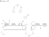
- FIG. 1 is a side view of a unit cell aligning device according to an embodiment of the present invention.
- a unit cell 10 aligning device includes a conveying unit 110, a vision unit 120, a gripper 130 and a control unit 140.
- the unit cell 10 includes electrodes 11 and 13 and a separation membrane 12.
- the unit cell 10 may have a structure in which the electrodes 11 and 13 and the separation membrane 12 are alternately laminated.
- the unit cell 10 may include the first electrode 11, the separation membrane 12 stacked on both sides of the first electrode 11, and the second electrode 13 stacked on each separation membrane 12 stacked on both sides of the first electrode 11, but the structure of the unit cell 10 is not limited thereto.
- first electrode 11 and the second electrode 13 may be an anode and the other may be a cathode.
- the first electrode 11 may be the anode and the second electrode 13 may be the cathode.
- a cross-sectional area of the first electrode 11 which is the anode may be larger than the cross-sectional area of the second electrode 13 which is the cathode.
- the cross-sectional area means a cross-sectional area on a plane defined by a first direction x and a second direction y.
- Each of the first electrode 11 and the second electrode 13 may have a structure in which a tab is formed at one end portion, but the tab of the electrode is omitted in the drawings.
- the separation membrane 12 is disposed between the electrodes 11 and 13.
- the cross-sectional area of the separation membrane 12 may be larger than the cross-sectional areas of the electrodes 11 and 13.
- the cross-sectional area of the first electrode 11 which is the anode may be larger than the cross-sectional area of the second electrode 13 which is the cathode. In this case, the cross-sectional area may decrease in order of the separation membrane 12, the first electrode 11 and the second electrode 13.
- the conveying unit 110 conveys the unit cells 10.
- the conveying unit 110 may include a first conveying unit 111 and a second conveying unit 112.
- the first conveying unit 111 conveys the unit cell 10 including the electrodes 11 and 13 and the separation membrane 12 in the first direction x.
- the first conveying unit 111 can continuously transport a plurality of unit cells 10 spaced apart from each other by a predetermined interval.
- the first conveying unit 111 may be a conveyor belt.
- the first conveying unit 111 may have a first area A1 that is an area in which the electrodes 11 and 13 are measured by a first vision unit 122, and a second area A2 that is an area in which the electrodes 11 and 13 are griped by a gripper 130 and measured by the second vision unit 122.
- the second conveying unit 112 conveys the separation membrane 20 and the unit cells 10 disposed on the separation membrane 20. At this time, the unit cell 10 is supplied to the second conveying unit 112 by the gripper 130 to be described later and can be seated on the separation membrane 20. Therefore, the stack/folding type electrode assembly can be formed by winding the separation membrane 20 with the unit cells 10 seated thereon in a subsequent process.
- the second conveying unit 112 may be a pair of rollers. Accordingly, the unit cell 10 can be loaded between the pair of rollers by the gripper 130 and pressed together with the separation membrane 20.
- the vision unit 120 can measure the positional information of the electrodes 11 and 13, specifically measure twisted angles of the electrodes 11 and 13. However, the vision unit 120 can also measure other types of positional information such as the positions of the electrodes 11 and 13 and the alignment state between the electrodes 11 and 13, and can measure the positional information of the separation membrane 12 depending on the design. Information measured by the vision unit 120 can be conveyed to the control unit 140.
- the vision unit 120 includes the first vision unit 121 and the second vision unit 122.
- Each of the first vision unit 121 and the second vision unit 122 can measure the twisted angle ⁇ 1 of the electrodes 11 and 13 in different areas.
- Each of the first vision unit 121 and the second vision unit 122 can include a vision device, which can be a camera, X-ray, or the like.
- the gripper 130 can serve to grip and move the unit cell 10. Specifically, the gripper 130 can grip the unit cell 10 and supply the gripped unit cell 10 to the second conveying unit 112. The gripper 130 can grip one end or both ends of the unit cell 10.
- the gripper 130 includes a body and an arm, and the arm can grip the unit cell 10 and move it while being fixed.
- the control unit 140 controls the gripper 130.
- the control unit 140 can control a moving distance, a moving speed, an angle, and the like of the gripper 130. At this time, the control unit 140 can control the gripper 130 on the basis of information measured by the vision unit 120.
- the vision unit 120, the gripper 130 and the control unit 140 of the unit cell aligning device will be described in more detail with reference to FIGS. 2 and 3 .
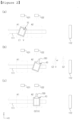
- FIG. 2 is a plan view for explaining alignment of a unit cell according to an embodiment of the present invention.
- the first conveying unit 111 has the first area A1 and the second area A2 adjacent to the first area A1.
- the unit cell 10 is conveyed along the first direction x, and the unit cell 10 sequentially passes through the first area A1 and the second area A2 accordingly.
- the first vision unit 121 is disposed on the first area A1 of the conveying unit 111
- the second vision unit 122 is disposed on the second area A2 of the conveying unit 111.
- the first area A1 is a first measurement area for measuring the unit cell 10 with the first vision unit 121
- the second area A2 is a second measurement area for measuring the unit cell 10 that has passed the first area A1 with the second vision unit 122.
- the unit cell 10 stops for a certain period of time in the first area A1 while being conveyed to the first conveying unit 111 and is measured by the first vision unit 121, and is conveyed again, stops for a certain period of time in the second area A2 and can be measured with the vision unit 122.
- the second area A2 may be an area in which the unit cell 10 is gripped by the gripper 130, as will be described later.
- the first area A1 and the second area A2 are areas introduced for convenience of explanation, and may not have boundaries that is visually confirmed with each other.
- each of the first vision unit 121 and the second vision unit 122 may be seen to be disposed on the second direction y of each of the first area A1 and the second area A2 of the first conveying unit 110, this is only for the purpose of helping understanding of the explanation, and each of the first vision unit 121 and the second vision unit 122 is disposed on a third direction z of each of the first area A1 and the second area A2 of the first conveying unit 110.
- the cross-sectional area of the separation membrane 12 may be larger than the cross-sectional areas of the electrodes 11 and 13, and the unit cell 10 is shown to have a structure in which the separation membrane 12 protrudes outside the outermost electrode 13 in the drawing.
- the first vision unit 121 measures the twisted angle ⁇ 1 of the electrodes 11 and 13 in the first area A1 of the first conveying unit 111.
- the twisted angle ⁇ 1 of the electrodes 11 and 13 is an angle that is formed by a virtual line V in the second direction y perpendicular to the first direction x on the plane and a central axis C1 of the electrodes 11 and 13.
- the central axis C1 of the electrodes 11 and 13 is a central axis in the second direction y when the electrodes 11 and 13 are not twisted and are ideally aligned.
- the central axis C1 of the misaligned electrodes 11 and 13 may not be directed in the second direction y.
- the first vision unit 121 measures the twisted angle ⁇ 1 of at least one of the first electrode 11 and the second electrode 13.
- the first vision unit 121 may measure the twisted angle ⁇ 1 of the first electrode 11.
- the first vision unit 121 can measure the twisted angle ⁇ 1 of the first electrode 11 disposed inside the unit cell 10 instead of the second electrode 13, which is the outermost electrode. Accordingly, the unit cells 10 can be aligned on the basis of the first electrode 11.
- the first electrode 11 may be an anode having a larger cross-sectional area than that of the second electrode 13, and thus overhang defect can be improved, by aligning the unit cells 10 on the basis of the first electrode 11 which is a cathode.
- the embodiment is not limited thereto, and the first vision unit 121 may measure the twisted angle of the second electrode 13 or measure the twisted angles of each of the first electrode 11 and the second electrode 13.
- the unit cell 10 is conveyed to the second area A2 of the first conveying unit 111, and the gripper 130 also moves to the second area A2 of the first conveying unit 111 to grip the unit cell 10.
- the control unit 140 adjusts an angle ⁇ 2 of the gripper 130 on the basis of the twisted angle ⁇ 1 of the electrodes 11 and 13 measured by the first vision unit 121 before the gripper 130 grips the unit cell 10. Specifically, the control unit 140 adjusts the angle ⁇ 2 of the gripper 130, by rotating the gripper 130 by the twisted angle ⁇ 1 of the electrodes 11 and 13. Therefore, the central axis C2 of the gripper 130 after adjustment is parallel to the central axis C1 of the electrode 11 and 13.
- the angle ⁇ 2 of the gripper 130 may be adjusted before movement of the gripper 130, and may also be adjusted during movement or after movement.
- the angle ⁇ 2 of the gripper 130 is an angle that is formed by the virtual line V in the second direction y perpendicular to the first direction x on the plane and the central axis C2 of the gripper 130.
- the central axis C2 of the gripper 130 is a central axis in the second direction y when the gripper 130 is in an unadjusted and aligned state. However, after adjustment as shown in the drawing, the central axis C2 of the gripper 130 may not be directed in the second direction y.
- the control unit 140 returns the gripper 130 so that the angle ⁇ 2 of the gripper 130 becomes the angle before adjustment.
- the control unit 140 rotates the gripper 130 again by the angle at which the gripper 130 rotates before gripping the unit cell 10 to return the gripper 130. Therefore, the central axis C2 of the gripper 130 is directed to the second direction y again, and becomes parallel to any virtual line V in the second direction y.
- the returned gripper 130 is still located in the second area A2 of the conveying unit 111.
- the unit cell aligning device grips the unit cell 10 in a state in which the electrodes 11 and 13 of the unit cell 10 are rotated by the twisted angle ⁇ 1, and returns the gripper 130 that grips the unit cell 10, thereby performing a primary alignment for the unit cell 10.
- further alignment of unit cells 10 may be performed as described below.
- FIG. 3 is a plan view for explaining further alignment of unit cells according to an embodiment of the present invention.
- the second vision unit 122 further measures the twisted angle ⁇ 1 of the electrodes 11 and 13, while being gripped by the gripper 130, after the gripper 130 returns in the second area A2 of the first conveying unit 111.
- the reason is that the alignment of the unit cells 10 needs to be aligned by the primary correction described in FIG. 2 , but alignment errors of the unit cells 10 may still occur due to errors in measurement or adjustment.
- the second vision unit 122 also measures the twisted angle ⁇ 1 of at least one of the first electrode 11 and the second electrode 13. It may be desirable for the second vision unit 122 to measure the twisted angle of the same electrode as the electrode measured by the first vision unit 121 in view of further alignment. For example, the second vision unit 122 may measure the twisted angle ⁇ 1 of the first electrode 11 which is the anode, in the same way as the first vision unit 121. However, the embodiment is not limited thereto, and the second vision unit 122 may measure the twisted angle of the second electrode 13 together with the first vision unit 121, or measure the twisted angle of each of the first electrode 11 and the second electrode 13. If necessary, the twisted angle of an electrode different from the electrode measured by the first vision unit 121 can also be measured.
- the control unit 140 further adjusts the angle ⁇ 2 of the returned gripper 130 on the basis of the twisted angle ⁇ 1 of the electrodes 11 and 13 measured by the second vision unit 122. Specifically, the control unit 140 further adjusts the angle ⁇ 2 of the gripper 130, by rotating the gripper 130 by the twisted angle ⁇ 1 of the electrodes 11 and 13 after the gripper 130 returns. Therefore, the central axis C2 of the gripper 130 may not be directed to the second direction y again.
- the angle ⁇ 2 of the gripper 130 may be further adjusted in the second area A2 of the first conveying unit 111, may be adjusted during movement of the gripper 130 to the second conveying unit 112, or may be adjusted after movement.
- the control unit 140 can further control the gripper 130 to maintain the adjusted angle and supply the unit cell 10 to the second conveying unit 112. That is, the control unit 140 can control the gripper 130 gripping the unit cell 10 to maintain the adjusted angle and move the unit cell 10 to the second conveying unit 112 in the second area A2 of the first conveying unit 111. Therefore, the unit cells 10 can be supplied to the second carrier 112 with improved alignment.
- the alignment of the unit cell 10 can be corrected by controlling the angle ⁇ 2 of the gripper 130 that grips the unit cell 10. Also, the alignment of the unit cells 10 can be further improved by performing two corrections before and after the unit cells 10 are gripped by the gripper 130. In addition, by providing the unit cells 10 in an aligned state, the alignment accuracy of the unit cells 10 seated on the separation membrane 20 can be improved, and folding gap defects can also be improved accordingly. In addition, by aligning the unit cells 10 on the basis of the first electrode 11 which is the anode, the overhang defect can be further improved.
- a unit cell aligning method of the present invention includes a step of conveying the unit cell 10 including the electrodes 11 and 13 and the separation membrane 12 in the first direction x, a step of measuring the twisted angle ⁇ 1 of the electrodes 11 and 13, a step of adjusting the angle ⁇ 2 of the gripper 130 on the basis of the measured twisted angle ⁇ 1 of the electrodes 11 and 13, a step of gripping the unit cell 10 with the gripper 130 whose angle is adjusted, and a step of returning the gripper 130 so that the angle ⁇ 2 of the gripper 130 gripping the unit cell 10 becomes an angle before adjustment.
- the unit cell aligning method of the present invention may further include a step of further measuring the twisted angle ⁇ 1 of the electrodes 11 and 13 after the gripper 130 is returned, and a step of further adjusting the angle ⁇ 2 of the gripper 130 on the basis of the additionally measured twisted angle of the electrodes 11 and 13.
- the unit cell conveying step may include a first conveying step of conveying the electrodes 11 and 13 to the first area A1 in which the twisted angle ⁇ 1 of the electrodes 11 and 13 is measured, and a second conveying step of conveying the electrodes 11 and 13 to the second area A2 gripped by the gripper 130.
- the step of further measuring the twisted angle ⁇ 2 of the electrodes 11 and 13 can be performed in the second area A2.
- first, second, etc. is to distinguish components from each other and does not mean a priority between components or an absolute order.
- a first component may be referred to as a second component in other parts of the specification.
Landscapes
- Engineering & Computer Science (AREA)
- Manufacturing & Machinery (AREA)
- Chemical & Material Sciences (AREA)
- Chemical Kinetics & Catalysis (AREA)
- Electrochemistry (AREA)
- General Chemical & Material Sciences (AREA)
- Physics & Mathematics (AREA)
- General Physics & Mathematics (AREA)
- Electromagnetism (AREA)
- Secondary Cells (AREA)
Abstract
Description
- The present application claims the benefit of priority based on
Korean Patent Application No. 10-2021-0101704 filed on August 3, 2021 - The present invention relates to a unit cell aligning device and method.
- With increasing technological development and demand for mobile devices, a rechargeable secondary battery is widely used as energy sources for various mobile devices. In addition, the secondary battery is attracting attention as an energy source for an electric vehicle, a hybrid vehicle and the like, which are proposed as a solution to air pollution caused by existing gasoline and diesel vehicles.
- The secondary battery is classified into a coin-shaped battery, a cylindrical battery, a rectangular battery, and a pouch-shaped battery according to the shape of the battery case in which the electrode assembly is incorporated. In general, an electrode assembly incorporated in the battery case is classified into a jelly-roll type in which a separation membrane is interposed and wound up between an anode and a cathode, a stack type in which a plurality of unit cells with the separation membrane interposed between the anode and the cathode are stacked, and a stack/folding type in which the unit cells are wound with a separation membrane.
- Among them, the stack/folding type can be manufactured by conveying the unit cells including the electrodes and the separation membrane, seating them on the separation membrane, and winding it with the separation membrane. At this time, if the electrodes are distorted during transportation of the unit cells, the unit cells are misaligned, and problems such as overhang defects may occur.
-
Korean Laid-open Patent Publication No. 10-2021-0055186 - An object of the present invention is to improve the alignment accuracy of unit cells seated on a separation membrane.
- Another object of the present invention is to improve overhang defects.
- Another object of the present invention is to improve folding gap defects.
- An embodiment of the present invention provides a unit cell alignment device, including: a first conveying unit which conveys a unit cell including an electrode and a separation membrane in a first direction; a first vision unit that measures a twisted angle of the electrode; a gripper that grips and moves the unit cell; and a control unit that controls the gripper, in which the control unit adjusts an angle of the gripper on the basis of the twisted angle of the electrode measured by the first vision unit before the gripper grips the unit cell, and returns the gripper so that the angle of the gripper becomes an angle before adjustment after the gripper grips the unit cell, the twisted angle of the electrode is an angle formed by a virtual line in a second direction perpendicular to the first direction on a plane and a central axis of the electrode, and the angle of the gripper is an angle formed between the virtual line in the second direction and a central axis of the gripper.
- An embodiment of the invention provides a unit cell aligning method, including: a step of conveying a unit cell including an electrode and a separation membrane in a first direction; a step of measuring a twisted angle of the electrode; a step of adjusting an angle of the gripper on the basis of the measured twisted angle of the electrode; a step of gripping the unit cell with the gripper having the adjusted angle; and a step of returning the gripper so that the angle of the gripper that grips the unit cell becomes an angle before adjustment, in which the twisted angle of the electrode is an angle formed by a virtual line in a second direction perpendicular to the first direction on a plane and a central axis of the electrode, and the angle of the gripper is an angle formed between the virtual line in the second direction and a central axis of the gripper.
- One of the effects of the present invention is to improve the alignment accuracy of the unit cells seated on the separation membrane.
- Another effect of the present invention is to improve overhang defects.
- Another effect of the present invention is to improve folding gap defects.
-
-
FIG. 1 is a side view of a unit cell aligning device according to an embodiment of the present invention. -
FIG. 2 is a plan view for explaining alignment of unit cells according to an embodiment of the present invention. -
FIG. 3 is a plan view for explaining further alignment of unit cells according to an embodiment of the present invention. - Embodiments of the present invention will now be described in detail with reference to the accompanying drawings. For convenience of explanation, all or part of each configuration may be expressed exaggeratedly in the drawings.
- Furthermore, the present invention is not limited to the accompanying drawings or the contents described in this specification, and it is obvious to those skilled in the art that the present invention can be embodied in various forms without departing from the technical spirit of the present invention.
-
FIG. 1 is a side view of a unit cell aligning device according to an embodiment of the present invention. - A
unit cell 10 aligning device according to an embodiment of the present invention includes aconveying unit 110, avision unit 120, agripper 130 and acontrol unit 140. - The
unit cell 10 includeselectrodes 11 and 13 and aseparation membrane 12. Specifically, theunit cell 10 may have a structure in which theelectrodes 11 and 13 and theseparation membrane 12 are alternately laminated. According to an embodiment of the present invention, theunit cell 10 may include the first electrode 11, theseparation membrane 12 stacked on both sides of the first electrode 11, and thesecond electrode 13 stacked on eachseparation membrane 12 stacked on both sides of the first electrode 11, but the structure of theunit cell 10 is not limited thereto. - One of the first electrode 11 and the
second electrode 13 may be an anode and the other may be a cathode. For example, the first electrode 11 may be the anode and thesecond electrode 13 may be the cathode. A cross-sectional area of the first electrode 11 which is the anode may be larger than the cross-sectional area of thesecond electrode 13 which is the cathode. Here, the cross-sectional area means a cross-sectional area on a plane defined by a first direction x and a second direction y. Each of the first electrode 11 and thesecond electrode 13 may have a structure in which a tab is formed at one end portion, but the tab of the electrode is omitted in the drawings. - The
separation membrane 12 is disposed between theelectrodes 11 and 13. The cross-sectional area of theseparation membrane 12 may be larger than the cross-sectional areas of theelectrodes 11 and 13. As described above, the cross-sectional area of the first electrode 11 which is the anode may be larger than the cross-sectional area of thesecond electrode 13 which is the cathode. In this case, the cross-sectional area may decrease in order of theseparation membrane 12, the first electrode 11 and thesecond electrode 13. - The
conveying unit 110 conveys theunit cells 10. Theconveying unit 110 may include a first conveying unit 111 and asecond conveying unit 112. - The first conveying unit 111 conveys the
unit cell 10 including theelectrodes 11 and 13 and theseparation membrane 12 in the first direction x. The first conveying unit 111 can continuously transport a plurality ofunit cells 10 spaced apart from each other by a predetermined interval. The first conveying unit 111 may be a conveyor belt. - As will be described later, the first conveying unit 111 may have a first area A1 that is an area in which the
electrodes 11 and 13 are measured by afirst vision unit 122, and a second area A2 that is an area in which theelectrodes 11 and 13 are griped by agripper 130 and measured by thesecond vision unit 122. - The
second conveying unit 112 conveys theseparation membrane 20 and theunit cells 10 disposed on theseparation membrane 20. At this time, theunit cell 10 is supplied to thesecond conveying unit 112 by thegripper 130 to be described later and can be seated on theseparation membrane 20. Therefore, the stack/folding type electrode assembly can be formed by winding theseparation membrane 20 with theunit cells 10 seated thereon in a subsequent process. - The
second conveying unit 112 may be a pair of rollers. Accordingly, theunit cell 10 can be loaded between the pair of rollers by thegripper 130 and pressed together with theseparation membrane 20. - The
vision unit 120 can measure the positional information of theelectrodes 11 and 13, specifically measure twisted angles of theelectrodes 11 and 13. However, thevision unit 120 can also measure other types of positional information such as the positions of theelectrodes 11 and 13 and the alignment state between theelectrodes 11 and 13, and can measure the positional information of theseparation membrane 12 depending on the design. Information measured by thevision unit 120 can be conveyed to thecontrol unit 140. - The
vision unit 120 includes thefirst vision unit 121 and thesecond vision unit 122. Each of thefirst vision unit 121 and thesecond vision unit 122 can measure the twisted angle Θ1 of theelectrodes 11 and 13 in different areas. Each of thefirst vision unit 121 and thesecond vision unit 122 can include a vision device, which can be a camera, X-ray, or the like. - The
gripper 130 can serve to grip and move theunit cell 10. Specifically, thegripper 130 can grip theunit cell 10 and supply thegripped unit cell 10 to thesecond conveying unit 112. Thegripper 130 can grip one end or both ends of theunit cell 10. Thegripper 130 includes a body and an arm, and the arm can grip theunit cell 10 and move it while being fixed. - The
control unit 140 controls thegripper 130. Thecontrol unit 140 can control a moving distance, a moving speed, an angle, and the like of thegripper 130. At this time, thecontrol unit 140 can control thegripper 130 on the basis of information measured by thevision unit 120. - Hereinafter, the
vision unit 120, thegripper 130 and thecontrol unit 140 of the unit cell aligning device according to an embodiment of the present invention will be described in more detail with reference toFIGS. 2 and3 . -
FIG. 2 is a plan view for explaining alignment of a unit cell according to an embodiment of the present invention. - The first conveying unit 111 has the first area A1 and the second area A2 adjacent to the first area A1. The
unit cell 10 is conveyed along the first direction x, and theunit cell 10 sequentially passes through the first area A1 and the second area A2 accordingly. Thefirst vision unit 121 is disposed on the first area A1 of the conveying unit 111, and thesecond vision unit 122 is disposed on the second area A2 of the conveying unit 111. In other words, the first area A1 is a first measurement area for measuring theunit cell 10 with thefirst vision unit 121, and the second area A2 is a second measurement area for measuring theunit cell 10 that has passed the first area A1 with thesecond vision unit 122. At this time, theunit cell 10 stops for a certain period of time in the first area A1 while being conveyed to the first conveying unit 111 and is measured by thefirst vision unit 121, and is conveyed again, stops for a certain period of time in the second area A2 and can be measured with thevision unit 122. Further, the second area A2 may be an area in which theunit cell 10 is gripped by thegripper 130, as will be described later. On the other hand, the first area A1 and the second area A2 are areas introduced for convenience of explanation, and may not have boundaries that is visually confirmed with each other. - On the other hand, in
FIGS. 2 and3 , although each of thefirst vision unit 121 and thesecond vision unit 122 may be seen to be disposed on the second direction y of each of the first area A1 and the second area A2 of the first conveyingunit 110, this is only for the purpose of helping understanding of the explanation, and each of thefirst vision unit 121 and thesecond vision unit 122 is disposed on a third direction z of each of the first area A1 and the second area A2 of the first conveyingunit 110. - Further, as described above, the cross-sectional area of the
separation membrane 12 may be larger than the cross-sectional areas of theelectrodes 11 and 13, and theunit cell 10 is shown to have a structure in which theseparation membrane 12 protrudes outside theoutermost electrode 13 in the drawing. - Referring to
FIG. 2(a) , thefirst vision unit 121 measures the twisted angle Θ1 of theelectrodes 11 and 13 in the first area A1 of the first conveying unit 111. - In this specification, the twisted angle θ1 of the
electrodes 11 and 13 is an angle that is formed by a virtual line V in the second direction y perpendicular to the first direction x on the plane and a central axis C1 of theelectrodes 11 and 13. The central axis C1 of theelectrodes 11 and 13 is a central axis in the second direction y when theelectrodes 11 and 13 are not twisted and are ideally aligned. However, the central axis C1 of themisaligned electrodes 11 and 13 may not be directed in the second direction y. - The
first vision unit 121 measures the twisted angle θ1 of at least one of the first electrode 11 and thesecond electrode 13. Thefirst vision unit 121 may measure the twisted angle Θ1 of the first electrode 11. Thefirst vision unit 121 can measure the twisted angle θ1 of the first electrode 11 disposed inside theunit cell 10 instead of thesecond electrode 13, which is the outermost electrode. Accordingly, theunit cells 10 can be aligned on the basis of the first electrode 11. As described above, the first electrode 11 may be an anode having a larger cross-sectional area than that of thesecond electrode 13, and thus overhang defect can be improved, by aligning theunit cells 10 on the basis of the first electrode 11 which is a cathode. However, the embodiment is not limited thereto, and thefirst vision unit 121 may measure the twisted angle of thesecond electrode 13 or measure the twisted angles of each of the first electrode 11 and thesecond electrode 13. - Referring to
FIG. 2(b) , theunit cell 10 is conveyed to the second area A2 of the first conveying unit 111, and thegripper 130 also moves to the second area A2 of the first conveying unit 111 to grip theunit cell 10. - At this time, the
control unit 140 adjusts an angle θ2 of thegripper 130 on the basis of the twisted angle θ1 of theelectrodes 11 and 13 measured by thefirst vision unit 121 before thegripper 130 grips theunit cell 10. Specifically, thecontrol unit 140 adjusts the angle θ2 of thegripper 130, by rotating thegripper 130 by the twisted angle Θ1 of theelectrodes 11 and 13. Therefore, the central axis C2 of thegripper 130 after adjustment is parallel to the central axis C1 of theelectrode 11 and 13. The angle Θ2 of thegripper 130 may be adjusted before movement of thegripper 130, and may also be adjusted during movement or after movement. - In this specification, the angle Θ2 of the
gripper 130 is an angle that is formed by the virtual line V in the second direction y perpendicular to the first direction x on the plane and the central axis C2 of thegripper 130. The central axis C2 of thegripper 130 is a central axis in the second direction y when thegripper 130 is in an unadjusted and aligned state. However, after adjustment as shown in the drawing, the central axis C2 of thegripper 130 may not be directed in the second direction y. - Referring to
FIG. 2(c) , after thegripper 130 grips theunit cell 10, thecontrol unit 140 returns thegripper 130 so that the angle Θ2 of thegripper 130 becomes the angle before adjustment. In other words, after thegripper 130 grips theunit cell 10, thecontrol unit 140 rotates thegripper 130 again by the angle at which thegripper 130 rotates before gripping theunit cell 10 to return thegripper 130. Therefore, the central axis C2 of thegripper 130 is directed to the second direction y again, and becomes parallel to any virtual line V in the second direction y. The returned gripper 130 is still located in the second area A2 of the conveying unit 111. - As described above, the unit cell aligning device according to an embodiment of the present invention grips the
unit cell 10 in a state in which theelectrodes 11 and 13 of theunit cell 10 are rotated by the twisted angle θ1, and returns thegripper 130 that grips theunit cell 10, thereby performing a primary alignment for theunit cell 10. However, even after such alignment, misalignment of theunit cells 10 may still occur. Therefore, according to an embodiment of the present invention, further alignment ofunit cells 10 may be performed as described below. -
FIG. 3 is a plan view for explaining further alignment of unit cells according to an embodiment of the present invention. - Referring to
FIG. 3(a) , thesecond vision unit 122 further measures the twisted angle θ1 of theelectrodes 11 and 13, while being gripped by thegripper 130, after thegripper 130 returns in the second area A2 of the first conveying unit 111. Ideally, the reason is that the alignment of theunit cells 10 needs to be aligned by the primary correction described inFIG. 2 , but alignment errors of theunit cells 10 may still occur due to errors in measurement or adjustment. - The
second vision unit 122 also measures the twisted angle Θ1 of at least one of the first electrode 11 and thesecond electrode 13. It may be desirable for thesecond vision unit 122 to measure the twisted angle of the same electrode as the electrode measured by thefirst vision unit 121 in view of further alignment. For example, thesecond vision unit 122 may measure the twisted angle θ1 of the first electrode 11 which is the anode, in the same way as thefirst vision unit 121. However, the embodiment is not limited thereto, and thesecond vision unit 122 may measure the twisted angle of thesecond electrode 13 together with thefirst vision unit 121, or measure the twisted angle of each of the first electrode 11 and thesecond electrode 13. If necessary, the twisted angle of an electrode different from the electrode measured by thefirst vision unit 121 can also be measured. - Referring to
FIG. 3(b) , thecontrol unit 140 further adjusts the angle θ2 of the returned gripper 130 on the basis of the twisted angle Θ1 of theelectrodes 11 and 13 measured by thesecond vision unit 122. Specifically, thecontrol unit 140 further adjusts the angle Θ2 of thegripper 130, by rotating thegripper 130 by the twisted angle Θ1 of theelectrodes 11 and 13 after thegripper 130 returns. Therefore, the central axis C2 of thegripper 130 may not be directed to the second direction y again. The angle Θ2 of thegripper 130 may be further adjusted in the second area A2 of the first conveying unit 111, may be adjusted during movement of thegripper 130 to the second conveyingunit 112, or may be adjusted after movement. - Referring to
FIG. 3(c) , thecontrol unit 140 can further control thegripper 130 to maintain the adjusted angle and supply theunit cell 10 to the second conveyingunit 112. That is, thecontrol unit 140 can control thegripper 130 gripping theunit cell 10 to maintain the adjusted angle and move theunit cell 10 to the second conveyingunit 112 in the second area A2 of the first conveying unit 111. Therefore, theunit cells 10 can be supplied to thesecond carrier 112 with improved alignment. - As described above, according to an embodiment of the present invention, the alignment of the
unit cell 10 can be corrected by controlling the angle Θ2 of thegripper 130 that grips theunit cell 10. Also, the alignment of theunit cells 10 can be further improved by performing two corrections before and after theunit cells 10 are gripped by thegripper 130. In addition, by providing theunit cells 10 in an aligned state, the alignment accuracy of theunit cells 10 seated on theseparation membrane 20 can be improved, and folding gap defects can also be improved accordingly. In addition, by aligning theunit cells 10 on the basis of the first electrode 11 which is the anode, the overhang defect can be further improved. - A unit cell aligning method of the present invention includes a step of conveying the
unit cell 10 including theelectrodes 11 and 13 and theseparation membrane 12 in the first direction x, a step of measuring the twisted angle θ1 of theelectrodes 11 and 13, a step of adjusting the angle θ2 of thegripper 130 on the basis of the measured twisted angle Θ1 of theelectrodes 11 and 13, a step of gripping theunit cell 10 with thegripper 130 whose angle is adjusted, and a step of returning thegripper 130 so that the angle Θ2 of thegripper 130 gripping theunit cell 10 becomes an angle before adjustment. - In addition, the unit cell aligning method of the present invention may further include a step of further measuring the twisted angle Θ1 of the
electrodes 11 and 13 after thegripper 130 is returned, and a step of further adjusting the angle θ2 of thegripper 130 on the basis of the additionally measured twisted angle of theelectrodes 11 and 13. - On the other hand, the unit cell conveying step may include a first conveying step of conveying the
electrodes 11 and 13 to the first area A1 in which the twisted angle θ1 of theelectrodes 11 and 13 is measured, and a second conveying step of conveying theelectrodes 11 and 13 to the second area A2 gripped by thegripper 130. At this time, the step of further measuring the twisted angle Θ2 of theelectrodes 11 and 13 can be performed in the second area A2. - Since other descriptions are applicable in substantially the same manner as the description of the unit cell aligning device according to an embodiment of the present invention, detailed descriptions thereof will be omitted.
- Although the unit cell aligning device and method according to an embodiment of the present invention have been described above, the embodiments of the present invention are not limited to the above embodiments. Those skilled in the art will be able to modify and implement the present invention as appropriate with reference to the present specification and accompanying drawings without departing from the technical spirit of the present invention.
- In this specification, the order of first, second, etc. is to distinguish components from each other and does not mean a priority between components or an absolute order. In some parts of the specification, a first component may be referred to as a second component in other parts of the specification.
- In this specification, directions such as a first direction x, a second direction y, and a third direction z have been described on the basis of the drawings. Of course, the directions described herein can be described differently depending on the point of view.
- In this description, the terms and expressions herein should be interpreted broadly and not in a restrictive sense. As used herein, the term "comprising" does not exclude the presence or addition of one or more other components in addition to the recited components. In this specification, the singular forms include the plural forms unless the context clearly dictates otherwise. Further, each embodiment is combinable with each other, and unless inconsistent, and contents described in specific embodiment is applicable to other embodiments unless inconsistent.
-
- 10: Unit cell,
- 11: First electrode,
- 12: Separation membrane,
- 13: Second electrode,
- 20: Separation membrane,
- 110: conveying unit,
- 111: First conveying unit,
- 112: Second conveying unit,
- 120: Vision unit,
- 121: First vision unit,
- 122: Second vision unit,
- 130: Gripper,
- 140: Control unit
Claims (14)
- A unit cell aligning device, comprising:a first conveying unit which is configured to convey a unit cell including an electrode and a separation membrane in a first direction;a first vision unit that is configured to measure a twisted angle of the electrode;a gripper that is configured to grip and move the unit cell; anda control unit that is configured to control the gripper,wherein the control unit is configured to adjust an angle of the gripper from an aligned angle to a twisted angle of the electrode measured by the first vision unit before the gripper grips the unit cell, and the control unit is configured to return the gripper so that the angle of the gripper becomes the aligned angle after the gripper grips the unit cell,the twisted angle of the electrode is an angle formed by a central axis of the electrode relative to a virtual line in a second direction perpendicular to the first direction, andthe angle of the gripper is an angle formed by a central axis of the gripper relative to the virtual line in the second direction.
- The unit cell aligning device according to claim 1, wherein the control unit is configured to rotate the gripper from the virtual line to the twisted angle of the electrode, before the gripper grips the unit cell.
- The unit cell aligning device according to claim 1, wherein the electrode is a first electrode and the separation membrane is a first separation membrane, the unit cell further including a second separation membrane stacked on the first electrode opposite the first separation membrane and two second electrodes stacked on the first and second separation membranes respectively, and the first vision unit is configured to measure the twisted angle of the first electrode.
- The unit cell aligning device according to claim 3, wherein the first electrode is an anode, and the second electrode is a cathode.
- The unit cell aligning device according to claim 1, further comprising a second vision unit that is configured to measure a second twisted angle of the electrode after the gripper is returned, wherein the control unit is configured to further adjust the angle of the gripper from the aligned angle to the second twisted angle of the electrode measured by the second vision unit.
- The unit cell aligning device according to claim 5, wherein the control unit is configured to rotate the gripper from the virtual line to the second twisted angle of the electrode after the gripper is returned.
- The unit cell aligning device according to claim 5, wherein the electrode is a first electrode and the separation membrane is a first separation membrane, the unit cell further including, a second separation membrane stacked on the first electrode opposite the first separation membrane and two second electrodes stacked on the first and second separation membranes respectively, and each of the first vision unit and the second vision unit are each configured to measure the twisted angle of the first electrode.
- The unit cell aligning device according to claim 7, wherein the first electrode is an anode, and the second electrode is a cathode.
- The unit cell aligning device according to claim 5, wherein the first vision unit is configured to measure the twisted angle of the electrode in a first area of the first conveying unit, the gripper is configured to grip the electrode in a second area of the first conveying unit adjacent to the first area, and the second vision unit is configured to measure the second twisted angle of the electrode in the second area of the first conveying unit.
- The unit cell aligning device according to claim 5, wherein the separation membrane is a first separation membrane, the unit cell aligning device further comprising a second conveying unit that is configured to convey a second separation membrane, the unit cell being disposed on the second separation membrane, wherein the gripper is configured to move the unit cell and is configured to transfer the unit cell to the second conveying unit, and the control unit is further configured to control the gripper to maintain the aligned angle and to transfer the unit cell to the second conveying unit.
- A unit cell aligning method, comprising:conveying a unit cell including an electrode and a separation membrane in a first direction;measuring a twisted angle of the electrode;adjusting an angle of the gripper from an aligned angle to a measured twisted angle of the electrode;gripping the unit cell with the gripper having the twisted angle; andreturning the gripper so that the angle of the gripper that is gripping the unit cell becomes the aligned angle,wherein the twisted angle of the electrode is an angle formed by a central axis of the electrode relative to a virtual line in a second direction perpendicular to the first direction, andthe angle of the gripper is an angle formed by a central axis of the gripper relative to the virtual line in the second direction.
- The unit cell aligning method according to claim 11, further comprising:measuring a second twisted angle of the electrode after the returning of the gripper; andadjusting the angle of the gripper after the returning from the aligned angle to the second twisted angle of the electrode.
- The unit cell aligning method according to claim 12, wherein the conveying of the unit cell in the first direction includes a first conveying of the electrode to a first area in which the twisted angle of the electrode is measured, and a second conveying of the electrode to a second area in which the electrode is gripped by the gripper.
- The unit cell aligning method according to claim 13, wherein the measuring of the second twisted angle of the electrode is performed in the second area.
Applications Claiming Priority (2)
| Application Number | Priority Date | Filing Date | Title |
|---|---|---|---|
| KR1020210101704A KR102917429B1 (en) | 2021-08-03 | 2021-08-03 | Unit cell aligning device and method |
| PCT/KR2022/010488 WO2023013922A1 (en) | 2021-08-03 | 2022-07-19 | Unit cell alignment device and alignment method |
Publications (3)
| Publication Number | Publication Date |
|---|---|
| EP4343902A1 true EP4343902A1 (en) | 2024-03-27 |
| EP4343902A4 EP4343902A4 (en) | 2024-10-23 |
| EP4343902B1 EP4343902B1 (en) | 2025-10-29 |
Family
ID=85156109
Family Applications (1)
| Application Number | Title | Priority Date | Filing Date |
|---|---|---|---|
| EP22853301.4A Active EP4343902B1 (en) | 2021-08-03 | 2022-07-19 | Unit cell alignment device and alignment method |
Country Status (7)
| Country | Link |
|---|---|
| US (1) | US20240347752A1 (en) |
| EP (1) | EP4343902B1 (en) |
| JP (1) | JP7646971B2 (en) |
| KR (1) | KR102917429B1 (en) |
| CN (1) | CN117597807A (en) |
| ES (1) | ES3053748T3 (en) |
| WO (1) | WO2023013922A1 (en) |
Family Cites Families (12)
| Publication number | Priority date | Publication date | Assignee | Title |
|---|---|---|---|---|
| KR101334618B1 (en) * | 2010-12-02 | 2013-11-29 | 주식회사 엘지화학 | Device for Folding Electrode Assembly |
| KR101280068B1 (en) * | 2011-06-10 | 2013-06-28 | 주식회사 나래나노텍 | System for Stacking Electrodes |
| KR101280069B1 (en) * | 2011-06-23 | 2013-06-28 | 주식회사 나래나노텍 | System for Stacking Electrodes |
| KR101726785B1 (en) * | 2014-11-03 | 2017-04-13 | 주식회사 엘지화학 | Manufacturing Apparatus for Electrode Assembly Comprising Stitch Cutting Member and Stack and Electrode Assembly Manufactured Using the Same |
| KR102287768B1 (en) * | 2018-01-29 | 2021-08-10 | 주식회사 엘지에너지솔루션 | Electrode assembly manufacturing method and rechargeable battery manufacturing method |
| KR102521066B1 (en) * | 2018-01-30 | 2023-04-13 | 주식회사 엘지에너지솔루션 | Transport method and apparatus for unit cell |
| KR102044367B1 (en) * | 2019-02-01 | 2019-11-13 | (주)호명이엔지 | Apparatus for Stacking Electrodes and System for Stacking Electrodes Having the Same |
| KR102866064B1 (en) * | 2019-04-04 | 2025-09-30 | 주식회사 엘지에너지솔루션 | Carrying apparatus for unit cell |
| JP6888645B2 (en) * | 2019-05-08 | 2021-06-16 | トヨタ自動車株式会社 | Transfer device and transfer method |
| KR102820359B1 (en) | 2019-11-07 | 2025-06-13 | 주식회사 엘지에너지솔루션 | Folding type Electrode assembly and method for fabricating the same |
| KR102757891B1 (en) * | 2019-11-13 | 2025-01-22 | 주식회사 엘지에너지솔루션 | Electrode assembly manufacturing method and electrode assembly manufactured manufacturing device |
| KR102780966B1 (en) | 2020-02-10 | 2025-03-14 | 삼성전자 주식회사 | electronic device and method for operating high speed screen of the electronic device |
-
2021
- 2021-08-03 KR KR1020210101704A patent/KR102917429B1/en active Active
-
2022
- 2022-07-19 EP EP22853301.4A patent/EP4343902B1/en active Active
- 2022-07-19 WO PCT/KR2022/010488 patent/WO2023013922A1/en not_active Ceased
- 2022-07-19 CN CN202280047169.5A patent/CN117597807A/en active Pending
- 2022-07-19 ES ES22853301T patent/ES3053748T3/en active Active
- 2022-07-19 US US18/580,391 patent/US20240347752A1/en active Pending
- 2022-07-19 JP JP2023578099A patent/JP7646971B2/en active Active
Also Published As
| Publication number | Publication date |
|---|---|
| KR102917429B1 (en) | 2026-01-23 |
| WO2023013922A1 (en) | 2023-02-09 |
| US20240347752A1 (en) | 2024-10-17 |
| JP7646971B2 (en) | 2025-03-18 |
| ES3053748T3 (en) | 2026-01-26 |
| CN117597807A (en) | 2024-02-23 |
| KR20230020087A (en) | 2023-02-10 |
| EP4343902B1 (en) | 2025-10-29 |
| JP2024524954A (en) | 2024-07-09 |
| EP4343902A4 (en) | 2024-10-23 |
Similar Documents
| Publication | Publication Date | Title |
|---|---|---|
| KR101956763B1 (en) | Edge Position Control System for Secondary Battery Cell Manufacturing Machine | |
| US20200354166A1 (en) | Placement device and placement method | |
| KR101933550B1 (en) | System for Manufacturing Cell Stack of Secondary Battery | |
| KR20230018776A (en) | Manufacturing device and manufacturing method for electrode assembly | |
| KR102370758B1 (en) | Separator supply system of Secondary Battery | |
| KR20230135936A (en) | Machine for Manufacturing Cell Stack of Secondary Battery | |
| EP4372872A1 (en) | Cell packaging device | |
| KR20190059676A (en) | Apparatus and method of manufacturing electrode assembly | |
| KR20220050708A (en) | Electrode Manufacturing Apparatus Comprising Electrode Alignment Part and Electrode Assembly Manufacturing Apparatus Comprising the Same | |
| KR20230087255A (en) | Welding apparatus of electrode lead | |
| EP4343902A1 (en) | Unit cell alignment device and alignment method | |
| US11196076B2 (en) | Secondary battery manufacturing system for forming electrode assembly using unit cells manufactured by laminating | |
| KR200493852Y1 (en) | Electrode Lamination Device Comprising Feeding Conveyor | |
| KR20210134166A (en) | electrode cell manufacturing method of secondary battery | |
| EP4343903A1 (en) | Electrode cutting device and cell manufacturing device comprising same | |
| EP4340084B1 (en) | Electrode assembly folding device and electrode assembly folding method | |
| CN217444458U (en) | Device for manufacturing assembly | |
| KR20230033443A (en) | Unit cell aligning device and method | |
| KR20200131393A (en) | Electrode supply device | |
| KR20230127806A (en) | Manufacturing systmem and manufacturing method of electrode assembly | |
| US20250140889A1 (en) | Sheet connection device and method for secondary battery | |
| EP4340085B1 (en) | Electrode assembly folding apparatus and electrode assembly folding method | |
| KR102962591B1 (en) | Auto splicing apparatus for electrode and auto splicing process | |
| US20250149613A1 (en) | Unit Cell Manufacturing Device and Manufacturing Method | |
| US20240332482A1 (en) | Method and Apparatus for Processing Electrode Sheet |
Legal Events
| Date | Code | Title | Description |
|---|---|---|---|
| STAA | Information on the status of an ep patent application or granted ep patent |
Free format text: STATUS: THE INTERNATIONAL PUBLICATION HAS BEEN MADE |
|
| PUAI | Public reference made under article 153(3) epc to a published international application that has entered the european phase |
Free format text: ORIGINAL CODE: 0009012 |
|
| STAA | Information on the status of an ep patent application or granted ep patent |
Free format text: STATUS: REQUEST FOR EXAMINATION WAS MADE |
|
| 17P | Request for examination filed |
Effective date: 20231219 |
|
| AK | Designated contracting states |
Kind code of ref document: A1 Designated state(s): AL AT BE BG CH CY CZ DE DK EE ES FI FR GB GR HR HU IE IS IT LI LT LU LV MC MK MT NL NO PL PT RO RS SE SI SK SM TR |
|
| A4 | Supplementary search report drawn up and despatched |
Effective date: 20240924 |
|
| RIC1 | Information provided on ipc code assigned before grant |
Ipc: G01B 15/00 20060101ALI20240918BHEP Ipc: G01B 11/27 20060101ALI20240918BHEP Ipc: G01B 11/00 20060101ALI20240918BHEP Ipc: G01B 7/31 20060101ALI20240918BHEP Ipc: H01M 10/04 20060101AFI20240918BHEP |
|
| DAV | Request for validation of the european patent (deleted) | ||
| DAX | Request for extension of the european patent (deleted) | ||
| GRAP | Despatch of communication of intention to grant a patent |
Free format text: ORIGINAL CODE: EPIDOSNIGR1 |
|
| STAA | Information on the status of an ep patent application or granted ep patent |
Free format text: STATUS: GRANT OF PATENT IS INTENDED |
|
| INTG | Intention to grant announced |
Effective date: 20250708 |
|
| GRAS | Grant fee paid |
Free format text: ORIGINAL CODE: EPIDOSNIGR3 |
|
| GRAA | (expected) grant |
Free format text: ORIGINAL CODE: 0009210 |
|
| STAA | Information on the status of an ep patent application or granted ep patent |
Free format text: STATUS: THE PATENT HAS BEEN GRANTED |
|
| P01 | Opt-out of the competence of the unified patent court (upc) registered |
Free format text: CASE NUMBER: UPC_APP_4894_4343902/2025 Effective date: 20250827 |
|
| AK | Designated contracting states |
Kind code of ref document: B1 Designated state(s): AL AT BE BG CH CY CZ DE DK EE ES FI FR GB GR HR HU IE IS IT LI LT LU LV MC MK MT NL NO PL PT RO RS SE SI SK SM TR |
|
| REG | Reference to a national code |
Ref country code: CH Ref legal event code: F10 Free format text: ST27 STATUS EVENT CODE: U-0-0-F10-F00 (AS PROVIDED BY THE NATIONAL OFFICE) Effective date: 20251029 Ref country code: GB Ref legal event code: FG4D |
|
| REG | Reference to a national code |
Ref country code: DE Ref legal event code: R096 Ref document number: 602022024150 Country of ref document: DE |
|
| REG | Reference to a national code |
Ref country code: IE Ref legal event code: FG4D |
|
| REG | Reference to a national code |
Ref country code: ES Ref legal event code: FG2A Ref document number: 3053748 Country of ref document: ES Kind code of ref document: T3 Effective date: 20260126 |
|
| REG | Reference to a national code |
Ref country code: NL Ref legal event code: MP Effective date: 20251029 |
|
| REG | Reference to a national code |
Ref country code: LT Ref legal event code: MG9D |
|
| PG25 | Lapsed in a contracting state [announced via postgrant information from national office to epo] |
Ref country code: NO Free format text: LAPSE BECAUSE OF FAILURE TO SUBMIT A TRANSLATION OF THE DESCRIPTION OR TO PAY THE FEE WITHIN THE PRESCRIBED TIME-LIMIT Effective date: 20260129 |
|
| PG25 | Lapsed in a contracting state [announced via postgrant information from national office to epo] |
Ref country code: HR Free format text: LAPSE BECAUSE OF FAILURE TO SUBMIT A TRANSLATION OF THE DESCRIPTION OR TO PAY THE FEE WITHIN THE PRESCRIBED TIME-LIMIT Effective date: 20251029 Ref country code: AT Free format text: LAPSE BECAUSE OF FAILURE TO SUBMIT A TRANSLATION OF THE DESCRIPTION OR TO PAY THE FEE WITHIN THE PRESCRIBED TIME-LIMIT Effective date: 20251029 Ref country code: FI Free format text: LAPSE BECAUSE OF FAILURE TO SUBMIT A TRANSLATION OF THE DESCRIPTION OR TO PAY THE FEE WITHIN THE PRESCRIBED TIME-LIMIT Effective date: 20251029 |
|
| REG | Reference to a national code |
Ref country code: AT Ref legal event code: MK05 Ref document number: 1852701 Country of ref document: AT Kind code of ref document: T Effective date: 20251029 |
|
| PG25 | Lapsed in a contracting state [announced via postgrant information from national office to epo] |
Ref country code: NL Free format text: LAPSE BECAUSE OF FAILURE TO SUBMIT A TRANSLATION OF THE DESCRIPTION OR TO PAY THE FEE WITHIN THE PRESCRIBED TIME-LIMIT Effective date: 20251029 |
|
| PG25 | Lapsed in a contracting state [announced via postgrant information from national office to epo] |
Ref country code: RS Free format text: LAPSE BECAUSE OF FAILURE TO SUBMIT A TRANSLATION OF THE DESCRIPTION OR TO PAY THE FEE WITHIN THE PRESCRIBED TIME-LIMIT Effective date: 20260129 |
|
| PG25 | Lapsed in a contracting state [announced via postgrant information from national office to epo] |
Ref country code: IS Free format text: LAPSE BECAUSE OF FAILURE TO SUBMIT A TRANSLATION OF THE DESCRIPTION OR TO PAY THE FEE WITHIN THE PRESCRIBED TIME-LIMIT Effective date: 20260228 |
|
| PG25 | Lapsed in a contracting state [announced via postgrant information from national office to epo] |
Ref country code: PT Free format text: LAPSE BECAUSE OF FAILURE TO SUBMIT A TRANSLATION OF THE DESCRIPTION OR TO PAY THE FEE WITHIN THE PRESCRIBED TIME-LIMIT Effective date: 20260302 |
|
| PG25 | Lapsed in a contracting state [announced via postgrant information from national office to epo] |
Ref country code: PL Free format text: LAPSE BECAUSE OF FAILURE TO SUBMIT A TRANSLATION OF THE DESCRIPTION OR TO PAY THE FEE WITHIN THE PRESCRIBED TIME-LIMIT Effective date: 20251029 |
|
| PG25 | Lapsed in a contracting state [announced via postgrant information from national office to epo] |
Ref country code: LV Free format text: LAPSE BECAUSE OF FAILURE TO SUBMIT A TRANSLATION OF THE DESCRIPTION OR TO PAY THE FEE WITHIN THE PRESCRIBED TIME-LIMIT Effective date: 20251029 |