EP4343804A1 - Switch - Google Patents
Switch Download PDFInfo
- Publication number
- EP4343804A1 EP4343804A1 EP23194858.9A EP23194858A EP4343804A1 EP 4343804 A1 EP4343804 A1 EP 4343804A1 EP 23194858 A EP23194858 A EP 23194858A EP 4343804 A1 EP4343804 A1 EP 4343804A1
- Authority
- EP
- European Patent Office
- Prior art keywords
- groove portions
- housing
- switch
- embedded
- metal terminal
- Prior art date
- Legal status (The legal status is an assumption and is not a legal conclusion. Google has not performed a legal analysis and makes no representation as to the accuracy of the status listed.)
- Granted
Links
Images




Classifications
-
- H—ELECTRICITY
- H01—ELECTRIC ELEMENTS
- H01H—ELECTRIC SWITCHES; RELAYS; SELECTORS; EMERGENCY PROTECTIVE DEVICES
- H01H13/00—Switches having rectilinearly-movable operating part or parts adapted for pushing or pulling in one direction only, e.g. push-button switch
- H01H13/02—Details
- H01H13/04—Cases; Covers
- H01H13/06—Dustproof, splashproof, drip-proof, waterproof or flameproof casings
-
- H—ELECTRICITY
- H01—ELECTRIC ELEMENTS
- H01H—ELECTRIC SWITCHES; RELAYS; SELECTORS; EMERGENCY PROTECTIVE DEVICES
- H01H1/00—Contacts
- H01H1/58—Electric connections to or between contacts; Terminals
-
- H—ELECTRICITY
- H01—ELECTRIC ELEMENTS
- H01H—ELECTRIC SWITCHES; RELAYS; SELECTORS; EMERGENCY PROTECTIVE DEVICES
- H01H11/00—Apparatus or processes specially adapted for the manufacture of electric switches
- H01H11/04—Apparatus or processes specially adapted for the manufacture of electric switches of switch contacts
- H01H11/06—Fixing of contacts to carrier ; Fixing of contacts to insulating carrier
-
- H—ELECTRICITY
- H01—ELECTRIC ELEMENTS
- H01H—ELECTRIC SWITCHES; RELAYS; SELECTORS; EMERGENCY PROTECTIVE DEVICES
- H01H11/00—Apparatus or processes specially adapted for the manufacture of electric switches
- H01H11/0056—Apparatus or processes specially adapted for the manufacture of electric switches comprising a successive blank-stamping, insert-moulding and severing operation
-
- H—ELECTRICITY
- H01—ELECTRIC ELEMENTS
- H01H—ELECTRIC SWITCHES; RELAYS; SELECTORS; EMERGENCY PROTECTIVE DEVICES
- H01H13/00—Switches having rectilinearly-movable operating part or parts adapted for pushing or pulling in one direction only, e.g. push-button switch
- H01H13/02—Details
- H01H13/10—Bases; Stationary contacts mounted thereon
-
- H—ELECTRICITY
- H01—ELECTRIC ELEMENTS
- H01H—ELECTRIC SWITCHES; RELAYS; SELECTORS; EMERGENCY PROTECTIVE DEVICES
- H01H13/00—Switches having rectilinearly-movable operating part or parts adapted for pushing or pulling in one direction only, e.g. push-button switch
- H01H13/50—Switches having rectilinearly-movable operating part or parts adapted for pushing or pulling in one direction only, e.g. push-button switch having a single operating member
- H01H13/52—Switches having rectilinearly-movable operating part or parts adapted for pushing or pulling in one direction only, e.g. push-button switch having a single operating member the contact returning to its original state immediately upon removal of operating force, e.g. bell-push switch
-
- H—ELECTRICITY
- H01—ELECTRIC ELEMENTS
- H01H—ELECTRIC SWITCHES; RELAYS; SELECTORS; EMERGENCY PROTECTIVE DEVICES
- H01H13/00—Switches having rectilinearly-movable operating part or parts adapted for pushing or pulling in one direction only, e.g. push-button switch
- H01H13/70—Switches having rectilinearly-movable operating part or parts adapted for pushing or pulling in one direction only, e.g. push-button switch having a plurality of operating members associated with different sets of contacts, e.g. keyboard
- H01H13/88—Processes specially adapted for manufacture of rectilinearly movable switches having a plurality of operating members associated with different sets of contacts, e.g. keyboards
-
- H—ELECTRICITY
- H01—ELECTRIC ELEMENTS
- H01H—ELECTRIC SWITCHES; RELAYS; SELECTORS; EMERGENCY PROTECTIVE DEVICES
- H01H1/00—Contacts
- H01H1/58—Electric connections to or between contacts; Terminals
- H01H2001/5888—Terminals of surface mounted devices [SMD]
-
- H—ELECTRICITY
- H01—ELECTRIC ELEMENTS
- H01H—ELECTRIC SWITCHES; RELAYS; SELECTORS; EMERGENCY PROTECTIVE DEVICES
- H01H2203/00—Form of contacts
- H01H2203/028—Form of contacts embedded in layer material
-
- H—ELECTRICITY
- H01—ELECTRIC ELEMENTS
- H01H—ELECTRIC SWITCHES; RELAYS; SELECTORS; EMERGENCY PROTECTIVE DEVICES
- H01H2203/00—Form of contacts
- H01H2203/036—Form of contacts to solve particular problems
- H01H2203/038—Form of contacts to solve particular problems to be bridged by a dome shaped contact
-
- H—ELECTRICITY
- H01—ELECTRIC ELEMENTS
- H01H—ELECTRIC SWITCHES; RELAYS; SELECTORS; EMERGENCY PROTECTIVE DEVICES
- H01H2229/00—Manufacturing
- H01H2229/044—Injection moulding
- H01H2229/048—Insertion moulding
Definitions
- the present disclosure relates to a switch.
- Japanese Laid-Open Patent Publication No. 2020-113432 relates to an input device including a metal member, and discloses a technique of providing an intermediate portion embedded in a resin casing with recessed and projecting portions across the intermediate portion, thereby enhancing adhesiveness between the resin casing and the intermediate portion and suppressing entry of water into a housing portion of the resin casing from a gap between the metal member and the resin casing.
- the technique of Japanese Laid-Open Patent Publication No. 2020-113432 may cause entry of flux into a contact portion of the metal member through travelling of the flux in the intermediate portion of the metal member upon soldering for a terminal of the metal member.
- a switch includes a housing and a metal terminal that is insert-molded into the housing.
- the metal terminal includes a contact portion provided on a first side of the metal terminal, an external connection portion provided on a second side of the metal terminal, and an embedded portion provided between the contact portion and the external connection portion and embedded in the housing.
- the embedded portion groove portions are formed in a front surface of the metal terminal and a rear surface of the metal terminal, the groove portions in the front surface being formed at positions different from the groove portions in the rear surface.
- the groove portions extend in a widthwise direction that is a direction intersecting an extending direction of the embedded portion.
- a Z-axis direction in the drawings is referred to as an upward-and-downward direction
- a Y-axis direction in the drawings is referred to as a leftward-and-rightward direction
- an X-axis direction in the drawings is referred to as a forward-and-backward direction.
- a positive Z-axis direction is an upward direction
- a positive Y-axis direction is a rightward direction
- a positive X-axis direction is a forward direction.
- FIG. 1 is a perspective view of the outer appearance of the switch 100 according to one embodiment.
- the switch 100 is formed, as a whole, in a rectangular parallelepiped shape that is thin in the upward-and-downward direction (Z-axis direction).
- a top surface 160A and a housing portion 160B of the housing 160 are covered with an insulator 110 that is transparent.
- a bump portion 111 is formed in a shape that is projecting upward (positive Z-axis direction).
- a press body 120 is adhered to a rear surface (negative Z-axis side) of the bump portion 111.
- the switch 100 allows for a downward (negative Z-axis direction) pressing operation via the press body 120.
- the switch 100 is in an OFF state when the pressing operation is not applied to the press body.
- the switch 100 switches to be in an ON state when the downward (negative Z-axis direction) pressing operation is applied to the press body 120.
- FIG. 2 is an exploded perspective view of the switch 100 according to one embodiment.
- FIG. 3 is a cross-sectional perspective view of the switch 100 according to one embodiment, taken along the YZ plane.
- the switch 100 includes the housing 160, a metal contact 130, the press body 120, and the insulator 110 in order from the downward side (negative Z-axis side) in the drawings.
- the housing 160 is a member in the form of a container, and the member is formed in a rectangular parallelepiped shape that is thin in the upward-and-downward direction (Z-axis direction).
- the housing 160 has a rectangular shape in which the leftward-and-rightward direction (Y-axis direction) is a longitudinal direction and the forward-and-backward direction (X-axis direction) is a transverse direction.
- the housing 160 has a housing portion 160B formed in a shape that is recessed downward from the top surface 160A.
- the metal contact 130 is housed.
- the housing 160 uses a relatively hard insulating material (e.g., a hard resin) and is integrally formed with the central fixation contact member 170 and the peripheral fixation contact member 180 through insert molding.
- a bottom portion 160C of the housing portion 160B of the housing 160 includes a central portion 160Ca and a peripheral portion 160Cb.
- the central portion 160Ca is formed at the center of the bottom portion 160C.
- the central portion 160Ca is provided with a central fixation contact 171 included in the central fixation contact member 170.
- the peripheral portion 160Cb is formed at an outer side of the central portion 160Ca so as to surround the central portion 160Ca.
- the peripheral portion 160Cb has a higher height position than the central portion 160Ca.
- the peripheral portion 160Cb is provided with peripheral fixation contacts 181 included in the peripheral fixation contact member 180.
- the metal contact 130 is placed in the peripheral portion 160Cb.
- the central fixation contact member 170 and the peripheral fixation contact member 180 are members that are formed of metal and formed in a generally flat plate.
- the central fixation contact member 170 and the peripheral fixation contact member 180 are integrally formed with the housing 160 through insert molding.
- the central fixation contact member 170 and the peripheral fixation contact member 180 are formed by processing a metal plate with various processing methods (e.g., a pressing process, a bend process, or a laser process).
- the central fixation contact member 170 is one example of "metal terminal".
- the central fixation contact member 170 includes the central fixation contact 171 at a left-hand (negative Y-axis side) end portion and an external connection terminal 172 at a right-hand (positive Y-axis side) end portion.
- the central fixation contact 171 is one example of "contact portion” and disposed in the central portion 160Ca of the bottom portion 160C of the housing 160.
- the external connection terminal 172 is provided to project from the right-hand (positive Y-axis side) lateral surface of the housing 160 and is to be connected to the exterior.
- the other portions of the central fixation contact member 170 are embedded in the housing 160.
- the peripheral fixation contact member 180 includes: at the right-hand (positive Y-axis side) end portion, a pair of peripheral fixation contacts 181 that are along the forward-and-backward direction (X-axis direction); and an external connection terminal 182 at the left-hand (negative Y-axis side) end portion.
- the pair of peripheral fixation contacts 181 are disposed in the peripheral portion 160Cb of the bottom portion 160C of the housing 160.
- the external connection terminal 182 is provided to project from the left-hand (negative Y-axis side) lateral surface of the housing 160 and is to be connected to the exterior.
- the other portions of the peripheral fixation contact member 180 are embedded in the housing 160.
- the metal contact 130 is a dome-shaped member that is projecting upward (positive Z-axis direction) and includes a top portion 131 at the central portion thereof.
- the metal contact 130 is formed using one or more thin metal plates. In the present embodiment, as one example, the metal contact 130 is formed of two thin metal plates that are overlaid on top of each other.
- the metal contact 130 is housed in the housing portion 160B of the housing 160, and placed at the peripheral portion 160Cb of the bottom portion 160C of the housing portion 160B. Thereby, the metal contact 130 contacts the peripheral fixation contacts 181 provided at the peripheral portion 160Cb, and is electrically connected to the peripheral fixation contact member 180.
- the metal contact 130 is what is called "reverse spring".
- the top portion 131 In response to application of the pressing operation to the press body 120, the top portion 131 is pressed downward via the press body 120, and once a predetermined operation load has been exceeded, the top portion 131 rapidly elastically deforms into a recessed shape (reverse motion). Thereby, the metal contact 130 contacts the central fixation contact 171 at a rear portion of the top portion 131, and further is electrically connected to the central fixation contact member 170. The metal contact 130 returns to the original projecting shape by an elastic force upon release of the pressing force from the press body 120.
- the metal contact 130 is formed by partially cutting a circular dome-shaped metal plate in a plan view from above, and includes four leg portions 132 respectively projecting in four mutually different directions in the plan view from above.
- the four leg portions 132 of the metal contact 130 are placed in the peripheral portion 160Cb of the housing 160, and two leg portions 132 thereof contact the peripheral fixation contacts 181.
- the press body 120 is a member that is disposed above the top portion 131 of the metal contact 130 and within a rear space of the bump portion 111 of the insulator 110.
- the press body 120 is circular in a plan view from above and has a three-dimensional shape projecting upward from the top portion 131 of the metal contact 130.
- the press body 120 is formed of a resin material such as polyethylene terephthalate (PET).
- PET polyethylene terephthalate
- the press body 120 has a curved top surface portion contouring the bump portion 111 of the insulator 110.
- the press body 120 is adhered, on the top surface portion thereof, to a rear portion of the bump portion 111 of the insulator 110 by given adhesion means (e.g., laser welding).
- the press body 120 has such a three-dimensional shape that a hemispherical shape is collapsed in the upward-and-downward direction (Z-axis direction).
- the press body 120 may be, for example, a cylindrical shape or an ellipsoidal shape.
- the press body 120 is not limited to the press body that is circular in a plan view from above.
- the insulator 110 is a thin-sheet member disposed on the top surface 160A of the housing 160.
- the insulator 110 is formed of a resin material such as PET.
- the insulator 110 has approximately the same shape as the top surface 160A of the housing 160; i.e., an approximately rectangular shape in which the leftward-and-rightward direction (Y-axis direction) is a longitudinal direction and the forward-and-backward direction (X-axis direction) is a transverse direction.
- the insulator 110 covering the top surface 160A of the housing 160, the insulator 110 is adhered to the top surface 160A of the housing 160 by given adhesion means (e.g., laser welding).
- the insulator 110 closes an upper opening of the housing portion 160B of the housing 160, and seals the housing portion 160B.
- the bump portion 111 formed in a shape projecting upward (positive Z-axis direction) is formed.
- the press body 120 is adhered to the rear portion of the bump portion 111.
- the switch 100 when the pressing operation is not applied to the press body 120, the metal contact 130 contacts the peripheral fixation contacts 181 and does not contact the central fixation contact 171. Therefore, the switch 100 according to one embodiment is in an OFF state when the pressing operation is not applied to the press body 120.
- the switch 100 when the pressing operation is applied to the press body 120, the press body 120 pushes down the top portion 131 of the metal contact 130, and elastically deforms the top portion 131 of the metal contact 130 so as to be in a recessed shape (reverse motion). Thereby, the rear portion of the top portion 131 contacts the central fixation contact 171, and the metal contact 130 is electrically connected to the central fixation contact member 170. As a result, the switch 100 switches to be in an ON state through conduction, via the central fixation contact member 170, between: the central fixation contact member 170 and the central fixation contact 171; and the peripheral fixation contact member 180 and the peripheral fixation contacts 181.
- the metal contact 130 when the pressing operation applied to the press body 120 has been stopped, the metal contact 130 returns to the original projecting shape by its own elastic force. As a result, the metal contact 130 ceases being contact with the central fixation contact 171, and the switch 100 returns to be in an OFF state.
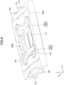
- FIG. 4 is a perspective view of the outer appearance of the housing 160 included in the switch 100 according to one embodiment.
- FIG. 5 is a perspective view of the outer appearance of the central fixation contact member 170 and the peripheral fixation contact member 180 included in the switch 100 according to one embodiment.
- FIG. 6 is a partially enlarged perspective view of the central fixation contact member 170 included in the switch 100 according to one embodiment.
- FIG. 7 is a partially enlarged cross-sectional view of the housing 160 included in the switch 100 according to one embodiment.
- the central fixation contact member 170 includes the central fixation contact 171 (one example of "contact portion") at the left-hand (negative Y-axis side) end portion and the external connection terminal 172 (one example of "external connection portion") at the right-hand (positive Y-axis side) end portion.
- the central fixation contact 171 is disposed in the central portion 160Ca of the bottom portion 160C of the housing 160.
- the external connection terminal 172 is provided to project from the right-hand (positive Y-axis side) lateral surface of the housing 160.
- the central fixation contact member 170 includes an embedded portion 173 between the central fixation contact 171 and the external connection terminal 172, the embedded portion 173 being to be embedded in the housing 160.
- the embedded portion 173 is extended in the leftward-and-rightward direction (Y-axis direction) that is an extending direction and in the forward-and-backward direction (X-axis direction) that is a widthwise direction. As illustrated in FIG. 6 , the embedded portion 173 has a plurality of groove portions 175 extending in the widthwise direction (X-axis direction), the groove portions 175 being alternately formed in a front surface 173A and in a rear surface 173B.
- the resin of the housing 160 enters the plurality of groove portions 175, thereby forming a plurality of wall portions 161 in the plurality of groove portions 175 (see FIG. 7 ).
- the plurality of wall portions 161 can prevent flux from spreading to (i.e., wetting) the central fixation contact 171 side (negative Y-axis side) from the external connection terminal 172 side (positive Y-axis side) in the front surface 173A and the rear surface 173B of the embedded portion 173.
- the outflow path of flux is expanded by the presence of the plurality of groove portions 175 in the front surface 173A and the rear surface 173B of the embedded portion 173. This also contributes to suppression of flux from spreading to (i.e., wetting) the central fixation contact 171 side (negative Y-axis side) from the external connection terminal 172 side (positive Y-axis side).
- the resin of the housing 160 enters the plurality of groove portions 175, thereby increasing adhesiveness between the resin of the housing 160 and the front surface 173A and the rear surface 173B of the embedded portion 173 (i.e., approximately no gap occurs therebetween). This also contributes to suppression of flux from spreading to (i.e., wetting) the central fixation contact 171 side (negative Y-axis side) from the external connection terminal 172 side (positive Y-axis side).
- the switch 100 therefore, when soldering is performed on the external connection terminal 172, it is possible to suppress entry of flux into the central fixation contact 171.
- the switch 100 has the plurality of groove portions 175 that are alternately formed in the front surface 173A and in the rear surface 173B. Therefore, as compared with a case where the groove portions 175 are formed at the same positions in the front surface 173A and the rear surface 173B of the embedded portion 173, each of the groove portions can be formed deeper, and thus it is possible to increase the effect of suppressing entry of flux.
- the embedded portion 173 includes a narrow-width portion 174 that is partially narrow in width, and the plurality of groove portions 175 are formed in the narrow-width portion 174.
- the groove portions 175 can be made shorter in length than in a case where the groove portions 175 are formed in the other portions of the embedded portion 173.
- groove portions 175 are formed in each of the front surface 173A and the rear surface 173B of the embedded portion 173, but three or more groove portions 175 may be formed.
- the cross-sectional shape of the groove portion 175 is a rectangular shape that is open in a top portion thereof.
- the cross-sectional shape of the groove portion 175 may be another shape (e.g., a V shape, a U shape, or a trapezoidal shape that is open in a top portion thereof).
- two groove portions 175 may be formed next to each other in each of the front surface 173A and the rear surface 173B of the embedded portion 173 such that the two groove portions 175 in the front surface 173A are formed at positions different from the two groove portions 175 in the rear surface 173B.
- the groove portions 175 are preferably formed through a laser process. Thereby, according to the switch 100 according to one embodiment, it is possible to form the groove portions 175 each having a cross-sectional shape becoming narrower in groove width as the groove portions become deeper and having an inner surface that is a coarse surface. This can increase the effect of entry of the resin of the housing 160 into the inner surfaces of the groove portions 175.
- the groove portions 175 preferably have such a length in the forward-and-backward (X-axis direction) that can completely traverse the narrow-width portion 174 (i.e., a length the same as the width of the narrow-width portion 174).
- the groove portions 175 are preferably orthogonal to the extending direction of the narrow-width portion 174. However, it is enough for the groove portions 175 to at least intersect the extending direction of the narrow-width portion 174.
- the depth of the groove portions 175 is preferably equal to or less than 50% of the plate thickness of the narrow-width portion 174.
- the depth of the groove portions 175 is preferably equal to or less than 25 micrometers.
- projecting bump portions may be formed along the edge portions of the groove portions 175 in the front surface 173A and the rear surface 173B of the embedded portion 173.
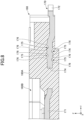
- FIG. 8 is a partially enlarged cross-sectional view of one modified example of the configuration of the housing 160 included in the switch 100 according to one embodiment.
- two groove portions 175 are formed in each of the front surface 173A and the rear surface 173B in the narrow-width portion 174 of the embedded portion 173 of the central fixation contact member 170. These groove portions 175 are formed alternately in the front surface 173A and in the rear surface 173B in the extending direction (Y-axis direction) of the central fixation contact member 170.
- the plurality of groove portions 175 are each formed through irradiation with laser light.
- each of the plurality of groove portions 175 that have been formed has a cross-sectional shape becoming narrower in groove width as the groove portions become deeper and has an inner surface that is a coarse surface.
- the switch 100 can increase the effect of entry of the resin of the housing 160 into the inner surfaces of the groove portions 175.
- bump portions 176 are formed along both left-hand and right-hand edge portions of each of the groove portions 175 in the narrow-width portion 174 of the embedded portion 173 of the central fixation contact member 170.
- the bump portions 176 are portions that are projecting in the upward-and-downward direction more than the front surface 173A and the rear surface 173B.
- the switch 100 includes the bump portions 176, and can increase the effect of entry of the resin of the housing 160 and the effect of suppressing entry of flux.
- the groove width of the groove portion 175 at a bottom end portion thereof is 0.01 mm.
- the groove width of the groove portion 175 at a top end portion thereof is 0.05 mm.
- the depth of the groove portion 175 relative to the front surface 173A and the rear surface 173B is 0.01 mm.
- the height of the bump portion 176 relative to the front surface 173A and the rear surface 173B is 0.01 mm.
Landscapes
- Engineering & Computer Science (AREA)
- Manufacturing & Machinery (AREA)
- Physics & Mathematics (AREA)
- Electromagnetism (AREA)
- Switch Cases, Indication, And Locking (AREA)
- Push-Button Switches (AREA)
- Manufacture Of Switches (AREA)
Abstract
Description
- The present disclosure relates to a switch.
-
Japanese Laid-Open Patent Publication No. 2020-113432 - The technique of
Japanese Laid-Open Patent Publication No. 2020-113432 - A switch according to one embodiment includes a housing and a metal terminal that is insert-molded into the housing. The metal terminal includes a contact portion provided on a first side of the metal terminal, an external connection portion provided on a second side of the metal terminal, and an embedded portion provided between the contact portion and the external connection portion and embedded in the housing. In the embedded portion, groove portions are formed in a front surface of the metal terminal and a rear surface of the metal terminal, the groove portions in the front surface being formed at positions different from the groove portions in the rear surface. The groove portions extend in a widthwise direction that is a direction intersecting an extending direction of the embedded portion.
- According to one embodiment, it is possible to suppress entry of flux into a contact portion of a metal terminal upon soldering for the metal terminal.
-
-
FIG. 1 is a perspective view of an outer appearance of a switch according to one embodiment; -
FIG. 2 is an exploded perspective view of the switch according to one embodiment; -
FIG. 3 is a cross-sectional perspective view of the switch according to one embodiment, taken along a YZ plane; -
FIG. 4 is a perspective view of an outer appearance of a housing included in the switch according to one embodiment; -
FIG. 5 is a perspective view of an outer appearance of a central fixation contact member and a peripheral fixation contact member included in the switch according to one embodiment; -
FIG. 6 is a partially enlarged perspective view of the central fixation contact member included in the switch according to one embodiment; -
FIG. 7 is a partially enlarged cross-sectional view of a housing included in the switch according to one embodiment; and -
FIG. 8 is a partially enlarged cross-sectional view of one modified example of the configuration of ahousing 160 included in aswitch 100 according to one embodiment. - Hereinafter, referring to the drawings, one embodiment will be described. Note in the following description that, for the sake of convenience, a Z-axis direction in the drawings is referred to as an upward-and-downward direction, a Y-axis direction in the drawings is referred to as a leftward-and-rightward direction, and an X-axis direction in the drawings is referred to as a forward-and-backward direction. However, a positive Z-axis direction is an upward direction, a positive Y-axis direction is a rightward direction, and a positive X-axis direction is a forward direction.
-
FIG. 1 is a perspective view of the outer appearance of theswitch 100 according to one embodiment. As illustrated inFIG. 1 , theswitch 100 is formed, as a whole, in a rectangular parallelepiped shape that is thin in the upward-and-downward direction (Z-axis direction). As illustrated inFIG. 1 , in theswitch 100, atop surface 160A and ahousing portion 160B of thehousing 160 are covered with aninsulator 110 that is transparent. At a central portion of theinsulator 110, abump portion 111 is formed in a shape that is projecting upward (positive Z-axis direction). Apress body 120 is adhered to a rear surface (negative Z-axis side) of thebump portion 111. Thereby, theswitch 100 allows for a downward (negative Z-axis direction) pressing operation via thepress body 120. - The
switch 100 is in an OFF state when the pressing operation is not applied to the press body. Theswitch 100 switches to be in an ON state when the downward (negative Z-axis direction) pressing operation is applied to thepress body 120. -
FIG. 2 is an exploded perspective view of theswitch 100 according to one embodiment.FIG. 3 is a cross-sectional perspective view of theswitch 100 according to one embodiment, taken along the YZ plane. As illustrated inFIG. 2 andFIG. 3 , theswitch 100 includes thehousing 160, ametal contact 130, thepress body 120, and theinsulator 110 in order from the downward side (negative Z-axis side) in the drawings. - The
housing 160 is a member in the form of a container, and the member is formed in a rectangular parallelepiped shape that is thin in the upward-and-downward direction (Z-axis direction). In a plan view from above, thehousing 160 has a rectangular shape in which the leftward-and-rightward direction (Y-axis direction) is a longitudinal direction and the forward-and-backward direction (X-axis direction) is a transverse direction. Thehousing 160 has ahousing portion 160B formed in a shape that is recessed downward from thetop surface 160A. In thehousing portion 160B, themetal contact 130 is housed. For example, thehousing 160 uses a relatively hard insulating material (e.g., a hard resin) and is integrally formed with the centralfixation contact member 170 and the peripheralfixation contact member 180 through insert molding. - A
bottom portion 160C of thehousing portion 160B of thehousing 160 includes a central portion 160Ca and a peripheral portion 160Cb. - The central portion 160Ca is formed at the center of the
bottom portion 160C. The central portion 160Ca is provided with acentral fixation contact 171 included in the centralfixation contact member 170. - The peripheral portion 160Cb is formed at an outer side of the central portion 160Ca so as to surround the central portion 160Ca. The peripheral portion 160Cb has a higher height position than the central portion 160Ca. The peripheral portion 160Cb is provided with
peripheral fixation contacts 181 included in the peripheralfixation contact member 180. Themetal contact 130 is placed in the peripheral portion 160Cb. - The central
fixation contact member 170 and the peripheralfixation contact member 180 are members that are formed of metal and formed in a generally flat plate. The centralfixation contact member 170 and the peripheralfixation contact member 180 are integrally formed with thehousing 160 through insert molding. For example, the centralfixation contact member 170 and the peripheralfixation contact member 180 are formed by processing a metal plate with various processing methods (e.g., a pressing process, a bend process, or a laser process). - The central
fixation contact member 170 is one example of "metal terminal". The centralfixation contact member 170 includes thecentral fixation contact 171 at a left-hand (negative Y-axis side) end portion and anexternal connection terminal 172 at a right-hand (positive Y-axis side) end portion. Thecentral fixation contact 171 is one example of "contact portion" and disposed in the central portion 160Ca of thebottom portion 160C of thehousing 160. Theexternal connection terminal 172 is provided to project from the right-hand (positive Y-axis side) lateral surface of thehousing 160 and is to be connected to the exterior. The other portions of the central fixation contact member 170 (portions other than thecentral fixation contact 171 and the external connection terminal 172) are embedded in thehousing 160. - The peripheral
fixation contact member 180 includes: at the right-hand (positive Y-axis side) end portion, a pair ofperipheral fixation contacts 181 that are along the forward-and-backward direction (X-axis direction); and anexternal connection terminal 182 at the left-hand (negative Y-axis side) end portion. The pair ofperipheral fixation contacts 181 are disposed in the peripheral portion 160Cb of thebottom portion 160C of thehousing 160. Theexternal connection terminal 182 is provided to project from the left-hand (negative Y-axis side) lateral surface of thehousing 160 and is to be connected to the exterior. The other portions of the peripheral fixation contact member 180 (portions other than theperipheral fixation contacts 181 and the external connection terminal 182) are embedded in thehousing 160. - The
metal contact 130 is a dome-shaped member that is projecting upward (positive Z-axis direction) and includes atop portion 131 at the central portion thereof. Themetal contact 130 is formed using one or more thin metal plates. In the present embodiment, as one example, themetal contact 130 is formed of two thin metal plates that are overlaid on top of each other. Themetal contact 130 is housed in thehousing portion 160B of thehousing 160, and placed at the peripheral portion 160Cb of thebottom portion 160C of thehousing portion 160B. Thereby, themetal contact 130 contacts theperipheral fixation contacts 181 provided at the peripheral portion 160Cb, and is electrically connected to the peripheralfixation contact member 180. Themetal contact 130 is what is called "reverse spring". In response to application of the pressing operation to thepress body 120, thetop portion 131 is pressed downward via thepress body 120, and once a predetermined operation load has been exceeded, thetop portion 131 rapidly elastically deforms into a recessed shape (reverse motion). Thereby, themetal contact 130 contacts thecentral fixation contact 171 at a rear portion of thetop portion 131, and further is electrically connected to the centralfixation contact member 170. Themetal contact 130 returns to the original projecting shape by an elastic force upon release of the pressing force from thepress body 120. - Note that, in the present embodiment, the
metal contact 130 is formed by partially cutting a circular dome-shaped metal plate in a plan view from above, and includes fourleg portions 132 respectively projecting in four mutually different directions in the plan view from above. In the present embodiment, the fourleg portions 132 of themetal contact 130 are placed in the peripheral portion 160Cb of thehousing 160, and twoleg portions 132 thereof contact theperipheral fixation contacts 181. - The
press body 120 is a member that is disposed above thetop portion 131 of themetal contact 130 and within a rear space of thebump portion 111 of theinsulator 110. Thepress body 120 is circular in a plan view from above and has a three-dimensional shape projecting upward from thetop portion 131 of themetal contact 130. Thepress body 120 is formed of a resin material such as polyethylene terephthalate (PET). Thepress body 120 has a curved top surface portion contouring thebump portion 111 of theinsulator 110. Thepress body 120 is adhered, on the top surface portion thereof, to a rear portion of thebump portion 111 of theinsulator 110 by given adhesion means (e.g., laser welding). In the present embodiment, thepress body 120 has such a three-dimensional shape that a hemispherical shape is collapsed in the upward-and-downward direction (Z-axis direction). However, this is by no means a limitation. Thepress body 120 may be, for example, a cylindrical shape or an ellipsoidal shape. Also, thepress body 120 is not limited to the press body that is circular in a plan view from above. - The
insulator 110 is a thin-sheet member disposed on thetop surface 160A of thehousing 160. Theinsulator 110 is formed of a resin material such as PET. In a plan view from above, theinsulator 110 has approximately the same shape as thetop surface 160A of thehousing 160; i.e., an approximately rectangular shape in which the leftward-and-rightward direction (Y-axis direction) is a longitudinal direction and the forward-and-backward direction (X-axis direction) is a transverse direction. With theinsulator 110 covering thetop surface 160A of thehousing 160, theinsulator 110 is adhered to thetop surface 160A of thehousing 160 by given adhesion means (e.g., laser welding). Theinsulator 110 closes an upper opening of thehousing portion 160B of thehousing 160, and seals thehousing portion 160B. At the central portion of theinsulator 110, thebump portion 111 formed in a shape projecting upward (positive Z-axis direction) is formed. As illustrated inFIG. 3 , thepress body 120 is adhered to the rear portion of thebump portion 111. - According to the
switch 100 according to one embodiment, when the pressing operation is not applied to thepress body 120, themetal contact 130 contacts theperipheral fixation contacts 181 and does not contact thecentral fixation contact 171. Therefore, theswitch 100 according to one embodiment is in an OFF state when the pressing operation is not applied to thepress body 120. - According to the
switch 100 according to one embodiment, when the pressing operation is applied to thepress body 120, thepress body 120 pushes down thetop portion 131 of themetal contact 130, and elastically deforms thetop portion 131 of themetal contact 130 so as to be in a recessed shape (reverse motion). Thereby, the rear portion of thetop portion 131 contacts thecentral fixation contact 171, and themetal contact 130 is electrically connected to the centralfixation contact member 170. As a result, theswitch 100 switches to be in an ON state through conduction, via the centralfixation contact member 170, between: the centralfixation contact member 170 and thecentral fixation contact 171; and the peripheralfixation contact member 180 and theperipheral fixation contacts 181. - Note that, according to the
switch 100 according to one embodiment, when the pressing operation applied to thepress body 120 has been stopped, themetal contact 130 returns to the original projecting shape by its own elastic force. As a result, themetal contact 130 ceases being contact with thecentral fixation contact 171, and theswitch 100 returns to be in an OFF state. -
FIG. 4 is a perspective view of the outer appearance of thehousing 160 included in theswitch 100 according to one embodiment.FIG. 5 is a perspective view of the outer appearance of the centralfixation contact member 170 and the peripheralfixation contact member 180 included in theswitch 100 according to one embodiment.FIG. 6 is a partially enlarged perspective view of the centralfixation contact member 170 included in theswitch 100 according to one embodiment.FIG. 7 is a partially enlarged cross-sectional view of thehousing 160 included in theswitch 100 according to one embodiment. - As illustrated in
FIG. 4 andFIG. 5 , the centralfixation contact member 170 includes the central fixation contact 171 (one example of "contact portion") at the left-hand (negative Y-axis side) end portion and the external connection terminal 172 (one example of "external connection portion") at the right-hand (positive Y-axis side) end portion. Thecentral fixation contact 171 is disposed in the central portion 160Ca of thebottom portion 160C of thehousing 160. Theexternal connection terminal 172 is provided to project from the right-hand (positive Y-axis side) lateral surface of thehousing 160. - Also, as illustrated in
FIG. 5 , the centralfixation contact member 170 includes an embeddedportion 173 between thecentral fixation contact 171 and theexternal connection terminal 172, the embeddedportion 173 being to be embedded in thehousing 160. - The embedded
portion 173 is extended in the leftward-and-rightward direction (Y-axis direction) that is an extending direction and in the forward-and-backward direction (X-axis direction) that is a widthwise direction. As illustrated inFIG. 6 , the embeddedportion 173 has a plurality ofgroove portions 175 extending in the widthwise direction (X-axis direction), thegroove portions 175 being alternately formed in afront surface 173A and in arear surface 173B. - Thereby, in the
switch 100 according to one embodiment, when thehousing 160 is insert-molded, the resin of thehousing 160 enters the plurality ofgroove portions 175, thereby forming a plurality ofwall portions 161 in the plurality of groove portions 175 (seeFIG. 7 ). - According to the
switch 100 according to one embodiment, therefore, when soldering is performed on theexternal connection terminal 172, the plurality ofwall portions 161 can prevent flux from spreading to (i.e., wetting) thecentral fixation contact 171 side (negative Y-axis side) from theexternal connection terminal 172 side (positive Y-axis side) in thefront surface 173A and therear surface 173B of the embeddedportion 173. - Also, according to the
switch 100 according to one embodiment, the outflow path of flux is expanded by the presence of the plurality ofgroove portions 175 in thefront surface 173A and therear surface 173B of the embeddedportion 173. This also contributes to suppression of flux from spreading to (i.e., wetting) thecentral fixation contact 171 side (negative Y-axis side) from theexternal connection terminal 172 side (positive Y-axis side). - Moreover, according to the
switch 100 according to one embodiment, the resin of thehousing 160 enters the plurality ofgroove portions 175, thereby increasing adhesiveness between the resin of thehousing 160 and thefront surface 173A and therear surface 173B of the embedded portion 173 (i.e., approximately no gap occurs therebetween). This also contributes to suppression of flux from spreading to (i.e., wetting) thecentral fixation contact 171 side (negative Y-axis side) from theexternal connection terminal 172 side (positive Y-axis side). - According to the
switch 100 according to one embodiment, therefore, when soldering is performed on theexternal connection terminal 172, it is possible to suppress entry of flux into thecentral fixation contact 171. - In particular, the
switch 100 according to one embodiment has the plurality ofgroove portions 175 that are alternately formed in thefront surface 173A and in therear surface 173B. Therefore, as compared with a case where thegroove portions 175 are formed at the same positions in thefront surface 173A and therear surface 173B of the embeddedportion 173, each of the groove portions can be formed deeper, and thus it is possible to increase the effect of suppressing entry of flux. - In particular, as illustrated in
FIG. 6 , the embeddedportion 173 includes a narrow-width portion 174 that is partially narrow in width, and the plurality ofgroove portions 175 are formed in the narrow-width portion 174. - Thereby, according to the
switch 100 according to one embodiment, thegroove portions 175 can be made shorter in length than in a case where thegroove portions 175 are formed in the other portions of the embeddedportion 173. - Note that, in the examples as illustrated in
FIG. 6 andFIG. 7 , twogroove portions 175 are formed in each of thefront surface 173A and therear surface 173B of the embeddedportion 173, but three ormore groove portions 175 may be formed. - Also, in the examples as illustrated in
FIG. 6 andFIG. 7 , the cross-sectional shape of thegroove portion 175 is a rectangular shape that is open in a top portion thereof. However, the cross-sectional shape of thegroove portion 175 may be another shape (e.g., a V shape, a U shape, or a trapezoidal shape that is open in a top portion thereof). Also, twogroove portions 175 may be formed next to each other in each of thefront surface 173A and therear surface 173B of the embeddedportion 173 such that the twogroove portions 175 in thefront surface 173A are formed at positions different from the twogroove portions 175 in therear surface 173B. - Also, the
groove portions 175 are preferably formed through a laser process. Thereby, according to theswitch 100 according to one embodiment, it is possible to form thegroove portions 175 each having a cross-sectional shape becoming narrower in groove width as the groove portions become deeper and having an inner surface that is a coarse surface. This can increase the effect of entry of the resin of thehousing 160 into the inner surfaces of thegroove portions 175. - Also, as illustrated in
FIG. 6 andFIG. 7 , thegroove portions 175 preferably have such a length in the forward-and-backward (X-axis direction) that can completely traverse the narrow-width portion 174 (i.e., a length the same as the width of the narrow-width portion 174). Thereby, according to theswitch 100 according to one embodiment, it is possible to increase the effect of thegroove portions 175 on suppression of entry of flux. - Also, as illustrated in
FIG. 6 andFIG. 7 , thegroove portions 175 are preferably orthogonal to the extending direction of the narrow-width portion 174. However, it is enough for thegroove portions 175 to at least intersect the extending direction of the narrow-width portion 174. - Also, the depth of the
groove portions 175 is preferably equal to or less than 50% of the plate thickness of the narrow-width portion 174. For example, when the plate thickness of the narrow-width portion 174 is 50 micrometers, the depth of thegroove portions 175 is preferably equal to or less than 25 micrometers. Thereby, theswitch 100 according to one embodiment can suppress reduction in strength of the narrow-width portion 174. - Also, when the
groove portions 175 are formed through a laser process, projecting bump portions may be formed along the edge portions of thegroove portions 175 in thefront surface 173A and therear surface 173B of the embeddedportion 173. In this case, according to theswitch 100 according to one embodiment, it is possible to further increase the effect of suppressing entry of flux by virtue of the bump portions. -
FIG. 8 is a partially enlarged cross-sectional view of one modified example of the configuration of thehousing 160 included in theswitch 100 according to one embodiment. - In the example as illustrated in
FIG. 8 , twogroove portions 175 are formed in each of thefront surface 173A and therear surface 173B in the narrow-width portion 174 of the embeddedportion 173 of the centralfixation contact member 170. Thesegroove portions 175 are formed alternately in thefront surface 173A and in therear surface 173B in the extending direction (Y-axis direction) of the centralfixation contact member 170. - Also, in the example as illustrated in
FIG. 8 , the plurality ofgroove portions 175 are each formed through irradiation with laser light. Thereby, each of the plurality ofgroove portions 175 that have been formed has a cross-sectional shape becoming narrower in groove width as the groove portions become deeper and has an inner surface that is a coarse surface. - Therefore, the
switch 100 according to one embodiment can increase the effect of entry of the resin of thehousing 160 into the inner surfaces of thegroove portions 175. - Also, in the example as illustrated in
FIG. 8 , since thegroove portions 175 have been formed through laser irradiation, bumpportions 176 are formed along both left-hand and right-hand edge portions of each of thegroove portions 175 in the narrow-width portion 174 of the embeddedportion 173 of the centralfixation contact member 170. Thebump portions 176 are portions that are projecting in the upward-and-downward direction more than thefront surface 173A and therear surface 173B. - The
switch 100 according to one embodiment includes thebump portions 176, and can increase the effect of entry of the resin of thehousing 160 and the effect of suppressing entry of flux. - Note that, as one example, the groove width of the
groove portion 175 at a bottom end portion thereof is 0.01 mm. Also, as one example, the groove width of thegroove portion 175 at a top end portion thereof is 0.05 mm. Also, as one example, the depth of thegroove portion 175 relative to thefront surface 173A and therear surface 173B is 0.01 mm. Also, as one example, the height of thebump portion 176 relative to thefront surface 173A and therear surface 173B is 0.01 mm. - While exemplary embodiments of the present invention have been described above in detail, the present invention is not limited to these embodiments. Various changes or modifications are possible within the scope of the gist of the present invention recited in the claims.
-
- 100
- switch
- 110
- insulator
- 111
- bump portion
- 120
- press body
- 130
- metal contact
- 131
- top portion
- 132
- leg portion
- 160
- housing
- 160A
- top surface
- 160B
- housing portion
- 160C
- bottom portion
- 160Ca
- central portion
- 160Cb
- peripheral portion
- 161
- wall portion
- 170
- central fixation contact member (metal terminal)
- 171
- central fixation contact (contact portion)
- 172
- external connection terminal (external connection portion)
- 173
- embedded portion
- 173A
- front surface
- 173B
- rear surface
- 174
- narrow-width portion
- 175
- groove portion
- 176
- bump portion
- 180
- peripheral fixation contact member
- 181
- peripheral fixation contact
- 182
- external connection terminal
Claims (7)
- A switch, comprising:a housing; anda metal terminal that is insert-molded into the housing,the metal terminal includinga contact portion provided on a first side of the metal terminal,an external connection portion provided on a second side of the metal terminal, andan embedded portion provided between the contact portion and the external connection portion and embedded in the housing,wherein in the embedded portion,groove portions are formed in a front surface of the metal terminal and a rear surface of the metal terminal, the groove portions in the front surface being formed at positions different from the groove portions in the rear surface, andthe groove portions extend in a widthwise direction that is a direction intersecting an extending direction of the embedded portion.
- The switch according to claim 1, wherein in the embedded portion, the groove portions are alternately formed in the front surface and in the rear surface.
- The switch according to claim 2, wherein the embedded portion includes a narrow-width portion that is partially narrow in width, and the groove portions are formed in the narrow-width portion.
- The switch according to any one of claims 1 to 3, wherein the groove portions are formed through a laser process.
- The switch according to claim 4, wherein the groove portions each have a cross-sectional shape becoming narrower in groove width as the groove portions become deeper.
- The switch according to claim 4, wherein the groove portions each have an inner surface that is a coarse surface.
- The switch according to claim 4, wherein in the embedded portion, bump portions are formed along edge portions of the groove portions.
Applications Claiming Priority (1)
| Application Number | Priority Date | Filing Date | Title |
|---|---|---|---|
| JP2022149125A JP2024043893A (en) | 2022-09-20 | 2022-09-20 | switch |
Publications (2)
| Publication Number | Publication Date |
|---|---|
| EP4343804A1 true EP4343804A1 (en) | 2024-03-27 |
| EP4343804B1 EP4343804B1 (en) | 2025-04-16 |
Family
ID=87929104
Family Applications (1)
| Application Number | Title | Priority Date | Filing Date |
|---|---|---|---|
| EP23194858.9A Active EP4343804B1 (en) | 2022-09-20 | 2023-09-01 | Switch |
Country Status (4)
| Country | Link |
|---|---|
| US (1) | US12562324B2 (en) |
| EP (1) | EP4343804B1 (en) |
| JP (1) | JP2024043893A (en) |
| CN (1) | CN117747330A (en) |
Families Citing this family (1)
| Publication number | Priority date | Publication date | Assignee | Title |
|---|---|---|---|---|
| CN115136272A (en) * | 2020-02-17 | 2022-09-30 | 阿尔卑斯阿尔派株式会社 | Push switch |
Citations (5)
| Publication number | Priority date | Publication date | Assignee | Title |
|---|---|---|---|---|
| US20180019077A1 (en) * | 2015-02-27 | 2018-01-18 | Panasonic Intellectual Property Management Co., Ltd. | Switch case and switch |
| WO2019093078A1 (en) * | 2017-11-13 | 2019-05-16 | アルプスアルパイン株式会社 | Switch device |
| US20200194197A1 (en) * | 2017-09-01 | 2020-06-18 | Panasonic Intellectual Property Management Co., Ltd. | Push switch |
| JP2020113432A (en) | 2019-01-10 | 2020-07-27 | パナソニックIpマネジメント株式会社 | Input device case and input device |
| US20210249202A1 (en) * | 2018-10-31 | 2021-08-12 | Alps Alpine Co., Ltd. | Switch device |
Family Cites Families (2)
| Publication number | Priority date | Publication date | Assignee | Title |
|---|---|---|---|---|
| JP2004319530A (en) * | 2003-02-28 | 2004-11-11 | Sanyo Electric Co Ltd | Optical semiconductor device and method of manufacturing the same |
| US7256360B1 (en) * | 2006-09-27 | 2007-08-14 | Tien-Ming Chou | Rolling-ball switch |
-
2022
- 2022-09-20 JP JP2022149125A patent/JP2024043893A/en active Pending
-
2023
- 2023-08-25 CN CN202311077790.9A patent/CN117747330A/en active Pending
- 2023-09-01 EP EP23194858.9A patent/EP4343804B1/en active Active
- 2023-09-14 US US18/467,161 patent/US12562324B2/en active Active
Patent Citations (5)
| Publication number | Priority date | Publication date | Assignee | Title |
|---|---|---|---|---|
| US20180019077A1 (en) * | 2015-02-27 | 2018-01-18 | Panasonic Intellectual Property Management Co., Ltd. | Switch case and switch |
| US20200194197A1 (en) * | 2017-09-01 | 2020-06-18 | Panasonic Intellectual Property Management Co., Ltd. | Push switch |
| WO2019093078A1 (en) * | 2017-11-13 | 2019-05-16 | アルプスアルパイン株式会社 | Switch device |
| US20210249202A1 (en) * | 2018-10-31 | 2021-08-12 | Alps Alpine Co., Ltd. | Switch device |
| JP2020113432A (en) | 2019-01-10 | 2020-07-27 | パナソニックIpマネジメント株式会社 | Input device case and input device |
Also Published As
| Publication number | Publication date |
|---|---|
| EP4343804B1 (en) | 2025-04-16 |
| JP2024043893A (en) | 2024-04-02 |
| US12562324B2 (en) | 2026-02-24 |
| US20240096566A1 (en) | 2024-03-21 |
| CN117747330A (en) | 2024-03-22 |
Similar Documents
| Publication | Publication Date | Title |
|---|---|---|
| JP2014212066A (en) | Switch | |
| US10755876B2 (en) | Push switch | |
| JP5083057B2 (en) | Push switch | |
| EP4343804B1 (en) | Switch | |
| TWI665696B (en) | Switch | |
| CN107546054B (en) | Push switch | |
| JP6660856B2 (en) | Switch device | |
| US10861658B2 (en) | Push switch | |
| CN103137362B (en) | Push switch | |
| US20190355531A1 (en) | Push switch | |
| WO2019044723A1 (en) | Push switch | |
| US10892119B2 (en) | Push switch | |
| JP7383199B2 (en) | switch device | |
| WO2024062651A1 (en) | Switch and insert molding method | |
| US11908640B2 (en) | Push switch | |
| US20190326078A1 (en) | Push switch | |
| US8455776B2 (en) | Push switch | |
| JP5911049B2 (en) | Push switch | |
| JP6949222B2 (en) | Push switch | |
| WO2020105339A1 (en) | Push switch | |
| JP5906703B2 (en) | Push switch | |
| JP2007311189A (en) | Automatic restoration type slide switch |
Legal Events
| Date | Code | Title | Description |
|---|---|---|---|
| PUAI | Public reference made under article 153(3) epc to a published international application that has entered the european phase |
Free format text: ORIGINAL CODE: 0009012 |
|
| STAA | Information on the status of an ep patent application or granted ep patent |
Free format text: STATUS: REQUEST FOR EXAMINATION WAS MADE |
|
| 17P | Request for examination filed |
Effective date: 20230901 |
|
| AK | Designated contracting states |
Kind code of ref document: A1 Designated state(s): AL AT BE BG CH CY CZ DE DK EE ES FI FR GB GR HR HU IE IS IT LI LT LU LV MC ME MK MT NL NO PL PT RO RS SE SI SK SM TR |
|
| STAA | Information on the status of an ep patent application or granted ep patent |
Free format text: STATUS: EXAMINATION IS IN PROGRESS |
|
| 17Q | First examination report despatched |
Effective date: 20240611 |
|
| GRAP | Despatch of communication of intention to grant a patent |
Free format text: ORIGINAL CODE: EPIDOSNIGR1 |
|
| STAA | Information on the status of an ep patent application or granted ep patent |
Free format text: STATUS: GRANT OF PATENT IS INTENDED |
|
| RIC1 | Information provided on ipc code assigned before grant |
Ipc: H01H 11/00 20060101ALN20241217BHEP Ipc: H01H 13/88 20060101ALN20241217BHEP Ipc: H01H 13/10 20060101ALN20241217BHEP Ipc: H01H 1/58 20060101ALI20241217BHEP Ipc: H01H 11/06 20060101AFI20241217BHEP |
|
| RIC1 | Information provided on ipc code assigned before grant |
Ipc: H01H 11/00 20060101ALN20241220BHEP Ipc: H01H 13/88 20060101ALN20241220BHEP Ipc: H01H 13/10 20060101ALN20241220BHEP Ipc: H01H 1/58 20060101ALI20241220BHEP Ipc: H01H 11/06 20060101AFI20241220BHEP |
|
| INTG | Intention to grant announced |
Effective date: 20250113 |
|
| GRAS | Grant fee paid |
Free format text: ORIGINAL CODE: EPIDOSNIGR3 |
|
| GRAA | (expected) grant |
Free format text: ORIGINAL CODE: 0009210 |
|
| STAA | Information on the status of an ep patent application or granted ep patent |
Free format text: STATUS: THE PATENT HAS BEEN GRANTED |
|
| AK | Designated contracting states |
Kind code of ref document: B1 Designated state(s): AL AT BE BG CH CY CZ DE DK EE ES FI FR GB GR HR HU IE IS IT LI LT LU LV MC ME MK MT NL NO PL PT RO RS SE SI SK SM TR |
|
| REG | Reference to a national code |
Ref country code: GB Ref legal event code: FG4D |
|
| REG | Reference to a national code |
Ref country code: CH Ref legal event code: EP |
|
| REG | Reference to a national code |
Ref country code: IE Ref legal event code: FG4D |
|
| REG | Reference to a national code |
Ref country code: DE Ref legal event code: R096 Ref document number: 602023002938 Country of ref document: DE |
|
| REG | Reference to a national code |
Ref country code: NL Ref legal event code: MP Effective date: 20250416 |
|
| PG25 | Lapsed in a contracting state [announced via postgrant information from national office to epo] |
Ref country code: NL Free format text: LAPSE BECAUSE OF FAILURE TO SUBMIT A TRANSLATION OF THE DESCRIPTION OR TO PAY THE FEE WITHIN THE PRESCRIBED TIME-LIMIT Effective date: 20250416 |
|
| REG | Reference to a national code |
Ref country code: AT Ref legal event code: MK05 Ref document number: 1786375 Country of ref document: AT Kind code of ref document: T Effective date: 20250416 |
|
| PG25 | Lapsed in a contracting state [announced via postgrant information from national office to epo] |
Ref country code: FI Free format text: LAPSE BECAUSE OF FAILURE TO SUBMIT A TRANSLATION OF THE DESCRIPTION OR TO PAY THE FEE WITHIN THE PRESCRIBED TIME-LIMIT Effective date: 20250416 Ref country code: ES Free format text: LAPSE BECAUSE OF FAILURE TO SUBMIT A TRANSLATION OF THE DESCRIPTION OR TO PAY THE FEE WITHIN THE PRESCRIBED TIME-LIMIT Effective date: 20250416 Ref country code: PT Free format text: LAPSE BECAUSE OF FAILURE TO SUBMIT A TRANSLATION OF THE DESCRIPTION OR TO PAY THE FEE WITHIN THE PRESCRIBED TIME-LIMIT Effective date: 20250818 |
|
| PGFP | Annual fee paid to national office [announced via postgrant information from national office to epo] |
Ref country code: DE Payment date: 20250919 Year of fee payment: 3 |
|
| REG | Reference to a national code |
Ref country code: LT Ref legal event code: MG9D |
|
| PG25 | Lapsed in a contracting state [announced via postgrant information from national office to epo] |
Ref country code: NO Free format text: LAPSE BECAUSE OF FAILURE TO SUBMIT A TRANSLATION OF THE DESCRIPTION OR TO PAY THE FEE WITHIN THE PRESCRIBED TIME-LIMIT Effective date: 20250716 Ref country code: GR Free format text: LAPSE BECAUSE OF FAILURE TO SUBMIT A TRANSLATION OF THE DESCRIPTION OR TO PAY THE FEE WITHIN THE PRESCRIBED TIME-LIMIT Effective date: 20250717 |
|
| PG25 | Lapsed in a contracting state [announced via postgrant information from national office to epo] |
Ref country code: PL Free format text: LAPSE BECAUSE OF FAILURE TO SUBMIT A TRANSLATION OF THE DESCRIPTION OR TO PAY THE FEE WITHIN THE PRESCRIBED TIME-LIMIT Effective date: 20250416 |
|
| PG25 | Lapsed in a contracting state [announced via postgrant information from national office to epo] |
Ref country code: BG Free format text: LAPSE BECAUSE OF FAILURE TO SUBMIT A TRANSLATION OF THE DESCRIPTION OR TO PAY THE FEE WITHIN THE PRESCRIBED TIME-LIMIT Effective date: 20250416 |
|
| PG25 | Lapsed in a contracting state [announced via postgrant information from national office to epo] |
Ref country code: HR Free format text: LAPSE BECAUSE OF FAILURE TO SUBMIT A TRANSLATION OF THE DESCRIPTION OR TO PAY THE FEE WITHIN THE PRESCRIBED TIME-LIMIT Effective date: 20250416 |
|
| PG25 | Lapsed in a contracting state [announced via postgrant information from national office to epo] |
Ref country code: AT Free format text: LAPSE BECAUSE OF FAILURE TO SUBMIT A TRANSLATION OF THE DESCRIPTION OR TO PAY THE FEE WITHIN THE PRESCRIBED TIME-LIMIT Effective date: 20250416 |
|
| PG25 | Lapsed in a contracting state [announced via postgrant information from national office to epo] |
Ref country code: RS Free format text: LAPSE BECAUSE OF FAILURE TO SUBMIT A TRANSLATION OF THE DESCRIPTION OR TO PAY THE FEE WITHIN THE PRESCRIBED TIME-LIMIT Effective date: 20250716 |
|
| PG25 | Lapsed in a contracting state [announced via postgrant information from national office to epo] |
Ref country code: IS Free format text: LAPSE BECAUSE OF FAILURE TO SUBMIT A TRANSLATION OF THE DESCRIPTION OR TO PAY THE FEE WITHIN THE PRESCRIBED TIME-LIMIT Effective date: 20250816 |
|
| PG25 | Lapsed in a contracting state [announced via postgrant information from national office to epo] |
Ref country code: LV Free format text: LAPSE BECAUSE OF FAILURE TO SUBMIT A TRANSLATION OF THE DESCRIPTION OR TO PAY THE FEE WITHIN THE PRESCRIBED TIME-LIMIT Effective date: 20250416 |
|
| PG25 | Lapsed in a contracting state [announced via postgrant information from national office to epo] |
Ref country code: DK Free format text: LAPSE BECAUSE OF FAILURE TO SUBMIT A TRANSLATION OF THE DESCRIPTION OR TO PAY THE FEE WITHIN THE PRESCRIBED TIME-LIMIT Effective date: 20250416 Ref country code: SM Free format text: LAPSE BECAUSE OF FAILURE TO SUBMIT A TRANSLATION OF THE DESCRIPTION OR TO PAY THE FEE WITHIN THE PRESCRIBED TIME-LIMIT Effective date: 20250416 |
|
| REG | Reference to a national code |
Ref country code: DE Ref legal event code: R097 Ref document number: 602023002938 Country of ref document: DE |
|
| PG25 | Lapsed in a contracting state [announced via postgrant information from national office to epo] |
Ref country code: CZ Free format text: LAPSE BECAUSE OF FAILURE TO SUBMIT A TRANSLATION OF THE DESCRIPTION OR TO PAY THE FEE WITHIN THE PRESCRIBED TIME-LIMIT Effective date: 20250416 |
|
| PG25 | Lapsed in a contracting state [announced via postgrant information from national office to epo] |
Ref country code: EE Free format text: LAPSE BECAUSE OF FAILURE TO SUBMIT A TRANSLATION OF THE DESCRIPTION OR TO PAY THE FEE WITHIN THE PRESCRIBED TIME-LIMIT Effective date: 20250416 |
|
| PG25 | Lapsed in a contracting state [announced via postgrant information from national office to epo] |
Ref country code: SK Free format text: LAPSE BECAUSE OF FAILURE TO SUBMIT A TRANSLATION OF THE DESCRIPTION OR TO PAY THE FEE WITHIN THE PRESCRIBED TIME-LIMIT Effective date: 20250416 |
|
| PG25 | Lapsed in a contracting state [announced via postgrant information from national office to epo] |
Ref country code: IT Free format text: LAPSE BECAUSE OF FAILURE TO SUBMIT A TRANSLATION OF THE DESCRIPTION OR TO PAY THE FEE WITHIN THE PRESCRIBED TIME-LIMIT Effective date: 20250416 |
|
| PLBE | No opposition filed within time limit |
Free format text: ORIGINAL CODE: 0009261 |
|
| STAA | Information on the status of an ep patent application or granted ep patent |
Free format text: STATUS: NO OPPOSITION FILED WITHIN TIME LIMIT |
|
| REG | Reference to a national code |
Ref country code: CH Ref legal event code: L10 Free format text: ST27 STATUS EVENT CODE: U-0-0-L10-L00 (AS PROVIDED BY THE NATIONAL OFFICE) Effective date: 20260225 |
|
| PG25 | Lapsed in a contracting state [announced via postgrant information from national office to epo] |
Ref country code: RO Free format text: LAPSE BECAUSE OF FAILURE TO SUBMIT A TRANSLATION OF THE DESCRIPTION OR TO PAY THE FEE WITHIN THE PRESCRIBED TIME-LIMIT Effective date: 20250416 |
|
| 26N | No opposition filed |
Effective date: 20260119 |