EP4343081A1 - Pillar particularly for canopies - Google Patents
Pillar particularly for canopies Download PDFInfo
- Publication number
- EP4343081A1 EP4343081A1 EP23020422.4A EP23020422A EP4343081A1 EP 4343081 A1 EP4343081 A1 EP 4343081A1 EP 23020422 A EP23020422 A EP 23020422A EP 4343081 A1 EP4343081 A1 EP 4343081A1
- Authority
- EP
- European Patent Office
- Prior art keywords
- arm
- support column
- mounting cavity
- adjustable arm
- foundation element
- Prior art date
- Legal status (The legal status is an assumption and is not a legal conclusion. Google has not performed a legal analysis and makes no representation as to the accuracy of the status listed.)
- Pending
Links
- 230000000295 complement effect Effects 0.000 claims abstract description 4
- 238000005452 bending Methods 0.000 description 2
- 230000009286 beneficial effect Effects 0.000 description 2
- 229910000831 Steel Inorganic materials 0.000 description 1
- 230000000712 assembly Effects 0.000 description 1
- 238000000429 assembly Methods 0.000 description 1
- 230000002146 bilateral effect Effects 0.000 description 1
- 230000015556 catabolic process Effects 0.000 description 1
- 238000006731 degradation reaction Methods 0.000 description 1
- 230000000694 effects Effects 0.000 description 1
- 230000005611 electricity Effects 0.000 description 1
- 230000005484 gravity Effects 0.000 description 1
- 238000009434 installation Methods 0.000 description 1
- 230000002452 interceptive effect Effects 0.000 description 1
- 238000004519 manufacturing process Methods 0.000 description 1
- 239000000463 material Substances 0.000 description 1
- 238000012986 modification Methods 0.000 description 1
- 230000004048 modification Effects 0.000 description 1
- 230000003068 static effect Effects 0.000 description 1
- 239000010959 steel Substances 0.000 description 1
Images


Classifications
-
- E—FIXED CONSTRUCTIONS
- E04—BUILDING
- E04H—BUILDINGS OR LIKE STRUCTURES FOR PARTICULAR PURPOSES; SWIMMING OR SPLASH BATHS OR POOLS; MASTS; FENCING; TENTS OR CANOPIES, IN GENERAL
- E04H6/00—Buildings for parking cars, rolling-stock, aircraft, vessels or like vehicles, e.g. garages
- E04H6/02—Small garages, e.g. for one or two cars
- E04H6/025—Small garages, e.g. for one or two cars in the form of an overhead canopy, e.g. carports
-
- E—FIXED CONSTRUCTIONS
- E04—BUILDING
- E04B—GENERAL BUILDING CONSTRUCTIONS; WALLS, e.g. PARTITIONS; ROOFS; FLOORS; CEILINGS; INSULATION OR OTHER PROTECTION OF BUILDINGS
- E04B1/00—Constructions in general; Structures which are not restricted either to walls, e.g. partitions, or floors or ceilings or roofs
- E04B1/18—Structures comprising elongated load-supporting parts, e.g. columns, girders, skeletons
- E04B1/24—Structures comprising elongated load-supporting parts, e.g. columns, girders, skeletons the supporting parts consisting of metal
- E04B1/2403—Connection details of the elongated load-supporting parts
-
- E—FIXED CONSTRUCTIONS
- E04—BUILDING
- E04C—STRUCTURAL ELEMENTS; BUILDING MATERIALS
- E04C3/00—Structural elongated elements designed for load-supporting
- E04C3/02—Joists; Girders, trusses, or trusslike structures, e.g. prefabricated; Lintels; Transoms; Braces
- E04C3/04—Joists; Girders, trusses, or trusslike structures, e.g. prefabricated; Lintels; Transoms; Braces of metal
- E04C3/08—Joists; Girders, trusses, or trusslike structures, e.g. prefabricated; Lintels; Transoms; Braces of metal with apertured web, e.g. with a web consisting of bar-like components; Honeycomb girders
-
- E—FIXED CONSTRUCTIONS
- E04—BUILDING
- E04C—STRUCTURAL ELEMENTS; BUILDING MATERIALS
- E04C3/00—Structural elongated elements designed for load-supporting
- E04C3/30—Columns; Pillars; Struts
- E04C3/32—Columns; Pillars; Struts of metal
-
- E—FIXED CONSTRUCTIONS
- E04—BUILDING
- E04C—STRUCTURAL ELEMENTS; BUILDING MATERIALS
- E04C3/00—Structural elongated elements designed for load-supporting
- E04C3/38—Arched girders or portal frames
- E04C3/40—Arched girders or portal frames of metal
-
- H—ELECTRICITY
- H02—GENERATION; CONVERSION OR DISTRIBUTION OF ELECTRIC POWER
- H02S—GENERATION OF ELECTRIC POWER BY CONVERSION OF INFRARED RADIATION, VISIBLE LIGHT OR ULTRAVIOLET LIGHT, e.g. USING PHOTOVOLTAIC [PV] MODULES
- H02S20/00—Supporting structures for PV modules
- H02S20/30—Supporting structures being movable or adjustable, e.g. for angle adjustment
-
- E—FIXED CONSTRUCTIONS
- E04—BUILDING
- E04B—GENERAL BUILDING CONSTRUCTIONS; WALLS, e.g. PARTITIONS; ROOFS; FLOORS; CEILINGS; INSULATION OR OTHER PROTECTION OF BUILDINGS
- E04B1/00—Constructions in general; Structures which are not restricted either to walls, e.g. partitions, or floors or ceilings or roofs
- E04B1/18—Structures comprising elongated load-supporting parts, e.g. columns, girders, skeletons
- E04B1/24—Structures comprising elongated load-supporting parts, e.g. columns, girders, skeletons the supporting parts consisting of metal
- E04B1/2403—Connection details of the elongated load-supporting parts
- E04B2001/2418—Details of bolting
-
- E—FIXED CONSTRUCTIONS
- E04—BUILDING
- E04B—GENERAL BUILDING CONSTRUCTIONS; WALLS, e.g. PARTITIONS; ROOFS; FLOORS; CEILINGS; INSULATION OR OTHER PROTECTION OF BUILDINGS
- E04B1/00—Constructions in general; Structures which are not restricted either to walls, e.g. partitions, or floors or ceilings or roofs
- E04B1/18—Structures comprising elongated load-supporting parts, e.g. columns, girders, skeletons
- E04B1/24—Structures comprising elongated load-supporting parts, e.g. columns, girders, skeletons the supporting parts consisting of metal
- E04B2001/249—Structures with a sloping roof
-
- F—MECHANICAL ENGINEERING; LIGHTING; HEATING; WEAPONS; BLASTING
- F24—HEATING; RANGES; VENTILATING
- F24S—SOLAR HEAT COLLECTORS; SOLAR HEAT SYSTEMS
- F24S25/00—Arrangement of stationary mountings or supports for solar heat collector modules
- F24S25/10—Arrangement of stationary mountings or supports for solar heat collector modules extending in directions away from a supporting surface
- F24S25/12—Arrangement of stationary mountings or supports for solar heat collector modules extending in directions away from a supporting surface using posts in combination with upper profiles
-
- Y—GENERAL TAGGING OF NEW TECHNOLOGICAL DEVELOPMENTS; GENERAL TAGGING OF CROSS-SECTIONAL TECHNOLOGIES SPANNING OVER SEVERAL SECTIONS OF THE IPC; TECHNICAL SUBJECTS COVERED BY FORMER USPC CROSS-REFERENCE ART COLLECTIONS [XRACs] AND DIGESTS
- Y02—TECHNOLOGIES OR APPLICATIONS FOR MITIGATION OR ADAPTATION AGAINST CLIMATE CHANGE
- Y02E—REDUCTION OF GREENHOUSE GAS [GHG] EMISSIONS, RELATED TO ENERGY GENERATION, TRANSMISSION OR DISTRIBUTION
- Y02E10/00—Energy generation through renewable energy sources
- Y02E10/40—Solar thermal energy, e.g. solar towers
- Y02E10/47—Mountings or tracking
-
- Y—GENERAL TAGGING OF NEW TECHNOLOGICAL DEVELOPMENTS; GENERAL TAGGING OF CROSS-SECTIONAL TECHNOLOGIES SPANNING OVER SEVERAL SECTIONS OF THE IPC; TECHNICAL SUBJECTS COVERED BY FORMER USPC CROSS-REFERENCE ART COLLECTIONS [XRACs] AND DIGESTS
- Y02—TECHNOLOGIES OR APPLICATIONS FOR MITIGATION OR ADAPTATION AGAINST CLIMATE CHANGE
- Y02E—REDUCTION OF GREENHOUSE GAS [GHG] EMISSIONS, RELATED TO ENERGY GENERATION, TRANSMISSION OR DISTRIBUTION
- Y02E10/00—Energy generation through renewable energy sources
- Y02E10/50—Photovoltaic [PV] energy
Definitions
- the invention falls within the area of building structures and relates to a pillar particularly for canopies.
- the aim of the present invention is to present a variable load-bearing structural element, a pillar, in particular for canopies, usable for example for car parking, which allows to change the inclination of the roofing part, without structural modifications, while maintaining the required static loading demands.
- the set aim is achieved by an invention, which is a pillar comprising a foundation element, a base anchored to the foundation element and a support column attached to the foundation element, on which a positionable arm is mounted, the essence of which is that the base is anchored to the foundation element in a dismountable manner and that the support column is also attached to the base in a dismountable manner, while the top end area of the support column has a mounting cavity open from the top, into which the rear end part of an adjustable arm is inserted, the adjustable arm being positionally adjustable on both sides within the mounting cavity.
- a pin is seated transversely across the mounting cavity in its bottom part, in a horizontal position, and at least one bottom open cut-out is formed transversely across the rear end part of the adjustable arm, the inner radius of which corresponds to the outer radius of the pin, with which it forms a complementary pair for swinging the adjustable arm in the mounting cavity.
- transverse through mounting holes are formed in the support column in the mounting cavity area and transverse through arm holes are formed in the rear end area of the positionally adjustable arm, the position of which corresponds to the position of the mounting holes for seating the fixing elements.
- a longitudinal gap open from above, is formed in the positionable arm, in the upper part of which a longitudinal support profile is embedded for fixing the transverse ladder-type profiles, while the transverse ladder-type profiles are adapted for fixing the photovoltaic panels.
- transverse through sidewall openings are formed in the side walls of the positionable arm gap and longitudinal sideways open fixing cavities are formed in the bottom of the support profile, in which shaped inserts are provided for fixing the support elements that are inserted into the sidewall openings.
- the present invention achieves a novel and superior effect in that the foundation element of the pillar does not rise above ground level, thereby increasing the variability of vehicle parking. It is further possible to change the slope of the roofing without interfering with the structure, while tilting it adequately can increase the efficiency of the photovoltaic panels, forming the actual roof layer.
- the dismountable connection of the base to both the support column and the foundation element allows an adjustment of the height of the entire structure by replacing the base.
- the pillar in the basic embodiment shown in Fig. 1 comprises an interlocking base 1 , a support column 2 and an adjustable arm 3 .
- Base 1 is anchored below the ground level 11 , in a dismountable manner, to the foundation element 101 , preferably embodied as a concrete block or pile.
- Support column 2 is preferably connected to base 1 in a dismountable manner.
- support column 2 is formed by two vertical flat mutually parallel column sidewalls 21 , transversely connected by undisplayed cross members running transversely through a column gap 22 that is located between the column sidewalls 21 .
- the longitudinal edges of the column sidewalls 21 are provided with collars 211 formed by bending the column sidewalls 21 into an L-shape outside the supporting column 2 .
- the column gap 22 is not guided by the cross members, thereby creating an assembly cavity 23 which is open from above and provides passage in front-to-rear direction.
- mounting holes 24 are formed in the column sidewalls 21 .
- the positionable arm 3 comprises two flat, mutually parallel arm sidewalls 31 , the surfaces of which are parallel to the plane of the surfaces of the column sidewalls 21 .
- the arm sidewalls 31 are transversely connected by non-displayed braces running transversely across the gap 33 situated between the arm sidewalls 31 , while the spacing of the outer surfaces of the arm sidewalls 31 corresponds to the spacing of the inner surfaces of the column sidewalls 21 .
- the longitudinal edges of the arm sidewalls 31 are provided with rails 311 , formed by bending the arm sidewalls 31 into an L-shape outside the positionable arm 3 .
- sidewall openings 37 are formed in the shoulder sidewalls 31 along their entire length, as shown in Fig. 5 .
- the bottom rails 311 are terminated at a distance from the ends of the shoulder sidewalls 31 adjacent to the support column 2 , which corresponds to at least the width of the upper end part of the column beam 2 in the area of its mounting cavity 23 , thus allowing the rear end area of the positionable arm 3 to be inserted into the mounting cavity 23 of the support column 2 .
- the shoulder sidewalls 31 are terminated in this area on their lower longitudinal side by mounting edges 34 .
- the support column 2 is fitted with pin 25 , which is fixed in the collar bodies 211 adjacent to the lower rails 311 of the adjustable arm 3 , as indicated in Figure 4 .
- semicircular cutouts 35 are formed in their end regions adjacent to the bottom rails 311 , the inner radius of which corresponds to the outer radius of pin 25 , with which the cut-outs form a complementary pair, so that when the end region of the positionable arm 3 is inserted into the mounting cavity 23 , the pin 25 is engaged in the semicircular cut-outs 35 .
- the support column 2 and the adjustable arm 3 are coupled to each other in a swinging manner.
- shoulder openings 32 are formed, whose position in swinging movement of the positionable arm 3 relative to the support column 2 corresponds successively to the position of the mounting holes 24 , while the shoulder openings 32 are formed in such a way that their line-up with the mounting holes 24 is always achieved at different angles of the positionable arm 3 relative to the support column 2 .
- the fixing elements 26 preferably a bolt or a rivet, are seated therein to establish the position of the adjustable arm 3 relative to the support column 2 .
- a longitudinal support profile 4 is provided at the top of the gap 33 , as indicated in Figure 3 and Figures 9 to 11 .
- longitudinal laterally open fixing cavities 41 are formed in the sides thereof, in which the shaped inserts 42 , into which the support elements 38 , preferably embodied in the form of bolts, are inserted, passing through the sidewall openings 37 in which they are fixed, as indicated in Fig. 10 and 11 .
- the support profiles 4 are supported transversely by the ladder-type profiles 5 on which photovoltaic panels 6 are mounted.
- the supporting pillar can be used particularly for building canopies for various purposes, for example for roofing car parking spaces and is usable for fixing photovoltaic panels.
Landscapes
- Engineering & Computer Science (AREA)
- Architecture (AREA)
- Civil Engineering (AREA)
- Structural Engineering (AREA)
- Physics & Mathematics (AREA)
- Electromagnetism (AREA)
- Earth Drilling (AREA)
- Conveying And Assembling Of Building Elements In Situ (AREA)
- Foundations (AREA)
- Forms Removed On Construction Sites Or Auxiliary Members Thereof (AREA)
- Photovoltaic Devices (AREA)
Abstract
A pillar comprising a foundation element (101), a base (1) anchored to the foundation element and a support column (2) attached to the foundation element, on which a positionable arm (3) is mounted, the essence of which invention is that the base (1) is anchored to the foundation element (101) in a dismountable method and that the support column is also attached to the base (1) in a dismountable method, while the top end area of the support column (2) has a mounting cavity (23) open from the top, into which the rear end part of an adjustable arm (3) is inserted, the adjustable arm (3) being positionally adjustable on both sides within the mounting cavity (23). A pin (25) is disposed transversely across the mounting cavity (23) in a horizontal position at the bottom thereof and at least one bottom open cut-out (35) is formed transversely across the rear end part of the adjustable arm (3), the inner radius of which corresponds to the outer radius of the pin (25) with which it forms a complementary pair for swinging the adjustable arm (3) in the mounting cavity (23)
Description
- The invention falls within the area of building structures and relates to a pillar particularly for canopies.
- In recent decades, the production of electricity from so-called renewable energy sources has become increasingly important. One option is to obtain it from sunlight through photovoltaic panels. These can be installed on any free surface, which may, however, result in the development and thus in the degradation of land stock. Nowadays, solar panel assemblies are increasingly being used on the roofs of houses or buildings or other canopies near residential or industrial buildings.
- There is a number of known solutions for the installation of photovoltaic panels using structures originally designed to cover partially or fully open spaces, such as bus stops or carports covering parking spaces and similar types of structures for other purposes, such as storage of materials. Fitting bus stops with photovoltaic panels is described, for example, in files
CN203961345U ,CN110424776A ,CN203383532U ,CN103452340A ,CN112523555A ,CN103850450A , where these are fixed structures without the possibility of adjusting the orientation of the panel surface to the sunlight. FileKR20200099854A EP2508694A1 describes the design of a covered parking space where the roof area is fitted with a solar panel assembly. The disadvantage of this solution is a concrete foundation above ground level, which limits the accessibility of the parking area. Side support columns are fixed in the concrete foundation, however, they are not adjustable. This concrete foundation, together with a steel side structure, is located in the area of doors of a parked automobile, which makes opening the doors significantly more difficult and takes up too much space around the vehicle. Furthermore, the solar panel assembly is placed on the roofing layer in this embodiment, so the solar panels do not form a separate roof cover layer. Therefore, it is not possible to change the slope and height of the cover layer without adjusting the lengths of the support pairs. Another design with an adjustable top is described in fileUS7531741B1 . Here, the axis of rotation for changing the inclination of the roof section is located in the centre of its centre of gravity and furthermore, this embodiment does not eliminate the above-mentioned problem with the location of the side support leg in the door area of a possibly parked vehicle under the structure. - The aim of the present invention is to present a variable load-bearing structural element, a pillar, in particular for canopies, usable for example for car parking, which allows to change the inclination of the roofing part, without structural modifications, while maintaining the required static loading demands.
- The set aim is achieved by an invention, which is a pillar comprising a foundation element, a base anchored to the foundation element and a support column attached to the foundation element, on which a positionable arm is mounted, the essence of which is that the base is anchored to the foundation element in a dismountable manner and that the support column is also attached to the base in a dismountable manner, while the top end area of the support column has a mounting cavity open from the top, into which the rear end part of an adjustable arm is inserted, the adjustable arm being positionally adjustable on both sides within the mounting cavity. A pin is seated transversely across the mounting cavity in its bottom part, in a horizontal position, and at least one bottom open cut-out is formed transversely across the rear end part of the adjustable arm, the inner radius of which corresponds to the outer radius of the pin, with which it forms a complementary pair for swinging the adjustable arm in the mounting cavity.
- In the preferred embodiment, transverse through mounting holes are formed in the support column in the mounting cavity area and transverse through arm holes are formed in the rear end area of the positionally adjustable arm, the position of which corresponds to the position of the mounting holes for seating the fixing elements.
- It is further beneficial if a longitudinal gap, open from above, is formed in the positionable arm, in the upper part of which a longitudinal support profile is embedded for fixing the transverse ladder-type profiles, while the transverse ladder-type profiles are adapted for fixing the photovoltaic panels.
- Finally, it is beneficial if transverse through sidewall openings are formed in the side walls of the positionable arm gap and longitudinal sideways open fixing cavities are formed in the bottom of the support profile, in which shaped inserts are provided for fixing the support elements that are inserted into the sidewall openings.
- The present invention achieves a novel and superior effect in that the foundation element of the pillar does not rise above ground level, thereby increasing the variability of vehicle parking. It is further possible to change the slope of the roofing without interfering with the structure, while tilting it adequately can increase the efficiency of the photovoltaic panels, forming the actual roof layer. The dismountable connection of the base to both the support column and the foundation element allows an adjustment of the height of the entire structure by replacing the base.
- Specific examples of the invention embodiments are shown in the accompanying drawings which present:
- Fig. 1
- an overall side view of the assembled pillar,
- Fig. 2
- an exploded slant view of the upper two parts of the pillar from the back from above,
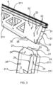
- Fig. 3
- an exploded detail view of the mutually adjacent end parts of the adjustable arm and the support column,
- Fig. 4
- a detailed front slanted view of the pin location in the upper end area of the support column,
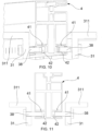
- Fig. 5
- a detail of the end regions of the adjustable arm and the support column connected at the upper limit position of the adjustable arm,
- Fig. 6
- a detail of the end regions of the adjustable arm and the support column connected at the lower limit position of the adjustable arm,
- Fig. 7
- a side view of the pillar showing the two extreme positions of inclination of the adjustable arm with a drawing of the lower foundation leg,
- Fig. 8
- an exploded detail view of an alternative embodiment of the connection area of the adjustable arm and the upper end area of the support column,
- Fig. 9
- a detail view of the bearing rail positioning in the adjustable arm from above, aslant,
- Fig. 10
- an enlarged detail view of the bearing rail positioning in the adjustable arm from
Fig. 7 , - Fig. 11
- a front view of the bearing rail positioning in the adjustable arm in section view, and
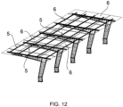
- Fig. 12
- an axonometric view of the pillar assembly with roofing.
- The drawings illustrating the present invention and the following examples of a particular embodiment do not in any way limit the scope of protection stipulated in the definition, but merely illustrate the principle of the invention.
- The pillar in the basic embodiment shown in
Fig. 1 comprises aninterlocking base 1, asupport column 2 and anadjustable arm 3.Base 1 is anchored below theground level 11, in a dismountable manner, to thefoundation element 101, preferably embodied as a concrete block or pile.Support column 2 is preferably connected tobase 1 in a dismountable manner. As illustrated inFig. 2 andFig. 3 ,support column 2 is formed by two vertical flat mutuallyparallel column sidewalls 21, transversely connected by undisplayed cross members running transversely through acolumn gap 22 that is located between thecolumn sidewalls 21. The longitudinal edges of thecolumn sidewalls 21 are provided withcollars 211 formed by bending thecolumn sidewalls 21 into an L-shape outside the supportingcolumn 2. In the upper end part of thesupport column 2, thecolumn gap 22 is not guided by the cross members, thereby creating anassembly cavity 23 which is open from above and provides passage in front-to-rear direction. In the area of themounting cavity 23, mountingholes 24 are formed in thecolumn sidewalls 21. According to the illustrations ofFig. 1 to Fig. 3 , thepositionable arm 3 comprises two flat, mutuallyparallel arm sidewalls 31, the surfaces of which are parallel to the plane of the surfaces of thecolumn sidewalls 21. The arm sidewalls 31 are transversely connected by non-displayed braces running transversely across thegap 33 situated between the arm sidewalls 31, while the spacing of the outer surfaces of the arm sidewalls 31 corresponds to the spacing of the inner surfaces of the column sidewalls 21. The longitudinal edges of the arm sidewalls 31 are provided withrails 311, formed by bending the arm sidewalls 31 into an L-shape outside thepositionable arm 3. Below theupper rails 311,sidewall openings 37 are formed in the shoulder sidewalls 31 along their entire length, as shown inFig. 5 . The bottom rails 311 are terminated at a distance from the ends of the shoulder sidewalls 31 adjacent to thesupport column 2, which corresponds to at least the width of the upper end part of thecolumn beam 2 in the area of its mountingcavity 23, thus allowing the rear end area of thepositionable arm 3 to be inserted into the mountingcavity 23 of thesupport column 2. The shoulder sidewalls 31 are terminated in this area on their lower longitudinal side by mountingedges 34. In the lower part of the mountingcavity 23, between the column sidewalls 21 in an axis perpendicular to their surface, thesupport column 2 is fitted withpin 25, which is fixed in thecollar bodies 211 adjacent to thelower rails 311 of theadjustable arm 3, as indicated inFigure 4 . In the mounting edges 34,semicircular cutouts 35 are formed in their end regions adjacent to the bottom rails 311, the inner radius of which corresponds to the outer radius ofpin 25, with which the cut-outs form a complementary pair, so that when the end region of thepositionable arm 3 is inserted into the mountingcavity 23, thepin 25 is engaged in the semicircular cut-outs 35. Thus, thesupport column 2 and theadjustable arm 3 are coupled to each other in a swinging manner. In the end regions of the shoulder sidewalls 31 adjacent to thesupport column 2,shoulder openings 32 are formed, whose position in swinging movement of thepositionable arm 3 relative to thesupport column 2 corresponds successively to the position of the mountingholes 24, while theshoulder openings 32 are formed in such a way that their line-up with the mountingholes 24 is always achieved at different angles of thepositionable arm 3 relative to thesupport column 2. As illustrated inFig. 5 and6 , when the arm holes 32 and the mountingholes 24 are mutually lined up, the fixingelements 26, preferably a bolt or a rivet, are seated therein to establish the position of theadjustable arm 3 relative to thesupport column 2. This enables to change and fix the relative inclination between thesupport column 2 and theadjustable arm 3, thus ensuring the bilateral adjustability of theadjustable arm 3, as indicated inFig. 5 to 7 . The described embodiment is not the only possible solution. In the end region of thepositionable arm 3 inserted in the mountingcavity 23, in the alternative embodiment indicated inFig. 8 , the arm holes 32 are replaced bycutouts 36 which are lined up with the mounting holes 24. The fixation of the position of theadjustable arm 3 is then achieved by a fixed bolt connection, whereby the inclination of theadjustable arm 3 can be changed continuously. Another alternative is to place thefoundation element 101 so that thebase 1 is anchored to it at or above ground level. - A
longitudinal support profile 4 is provided at the top of thegap 33, as indicated inFigure 3 andFigures 9 to 11 . In the lower part of thesupport profile 4, longitudinal laterally open fixingcavities 41 are formed in the sides thereof, in which the shaped inserts 42, into which thesupport elements 38, preferably embodied in the form of bolts, are inserted, passing through thesidewall openings 37 in which they are fixed, as indicated inFig. 10 and 11 . As outlined inFig. 12 , the support profiles 4 are supported transversely by the ladder-type profiles 5 on whichphotovoltaic panels 6 are mounted. - The supporting pillar can be used particularly for building canopies for various purposes, for example for roofing car parking spaces and is usable for fixing photovoltaic panels.
Claims (5)
- A pillar comprising a foundation element (101), a base (1) anchored to the foundation element and a support column (2) attached to the foundation element, on which a positionable arm (3) is mounted, characterized in that the base (1) is anchored to the foundation element (101) in a dismountable method and that the support column (2) is also attached to the base (1) in a dismountable method, while the top end area of the support column has a mounting cavity (23) open from the top, into which the rear end part of an adjustable arm (3) is inserted, the adjustable arm (3) being positionally adjustable on both sides within the mounting cavity (23), where a pin (25) is disposed transversely across the mounting cavity (23) in a horizontal position at the bottom thereof and at least one bottom open cut-out (35) is formed transversely across the rear end part of the adjustable arm (3), the inner radius of which corresponds to the outer radius of the pin (25) with which it forms a complementary pair for swinging the adjustable arm (3) in the mounting cavity (23).
- The pillar according to claim 1, characterized in that transverse through mounting holes (24) are formed in the support column (2) in the mounting cavity (23) area and transverse through arm openings (32) are formed in the rear end area of the positionally adjustable arm (3), the position of which corresponds to the position of the mounting holes (24) for seating the fixing elements (26)..
- Pillar according to any one of claims 1 or 2, characterized in that a longitudinal gap (33), open from above, is formed in the positionable arm (3), in the upper part of which a longitudinal bearing profile (4) is arranged for fixing the transverse ladder-type profiles (5).
- Pillar according to claim 3, characterized in that the transverse ladder-type profiles (5) are adapted for mounting photovoltaic panels (6).
- Pillar according to claim 3, characterized in that transverse through sidewall openings (37) are formed in the sidewalls of the positionable arm (3) gap (33) and longitudinal sideways open fixing cavities (41) are formed in the bottom of the support profile (4), in which shaped inserts (42) are provided for fixing the support elements (38) that are inserted into the sidewall openings (37).
Applications Claiming Priority (1)
| Application Number | Priority Date | Filing Date | Title |
|---|---|---|---|
| CZ2022-401A CZ309735B6 (en) | 2022-09-23 | 2022-09-23 | A pillar especially for shelters |
Publications (1)
| Publication Number | Publication Date |
|---|---|
| EP4343081A1 true EP4343081A1 (en) | 2024-03-27 |
Family
ID=87758340
Family Applications (1)
| Application Number | Title | Priority Date | Filing Date |
|---|---|---|---|
| EP23020422.4A Pending EP4343081A1 (en) | 2022-09-23 | 2023-09-07 | Pillar particularly for canopies |
Country Status (2)
| Country | Link |
|---|---|
| EP (1) | EP4343081A1 (en) |
| CZ (1) | CZ309735B6 (en) |
Citations (12)
| Publication number | Priority date | Publication date | Assignee | Title |
|---|---|---|---|---|
| CH694223A5 (en) * | 2000-06-15 | 2004-09-30 | Borra Sa | Noise or sound barrier provided with solar panels |
| DE202008005020U1 (en) * | 2008-04-10 | 2008-09-04 | Leichtmetallbau Schletter Gmbh | Mounting system for stands for photovoltaic ground-mounted systems |
| US7531741B1 (en) | 2003-03-07 | 2009-05-12 | Sacred Power Corporation | Tracking solar shelter |
| EP2508694A1 (en) | 2011-04-04 | 2012-10-10 | ARETANA Solar GmbH | Carport |
| CN103452340A (en) | 2012-05-29 | 2013-12-18 | 成都振中电气有限公司 | Solar bus shelter |
| CN203383532U (en) | 2013-08-06 | 2014-01-08 | 茅永夫 | Novel solar bus shelter |
| CN103850450A (en) | 2012-11-30 | 2014-06-11 | 飞秒光电科技(西安)有限公司 | Solar-powered bus shelter |
| CN203961345U (en) | 2014-07-08 | 2014-11-26 | 济宁市创佳户外家私有限公司 | A kind of solar energy bus shelter |
| WO2015111164A1 (en) * | 2014-01-23 | 2015-07-30 | ネクストエナジー・アンド・リソース株式会社 | Members for constituting stand for installing solar power generation panel |
| CN110424776A (en) | 2019-08-01 | 2019-11-08 | 江西欣盛泰实业有限公司 | The waiting booth of adjustable solar plate |
| KR20200099854A (en) | 2019-02-15 | 2020-08-25 | 주식회사 그린우전 | shelter having independent electric power system |
| CN112523555A (en) | 2020-12-11 | 2021-03-19 | 朱水仙 | Bus shelter structure with foldable solar panel |
Family Cites Families (8)
| Publication number | Priority date | Publication date | Assignee | Title |
|---|---|---|---|---|
| EP2292877A1 (en) * | 2009-09-02 | 2011-03-09 | Dhamma Asset Management | Photovoltaic solar energy generation and vehicle cover installation |
| JP4749509B1 (en) * | 2010-03-25 | 2011-08-17 | シャープ株式会社 | Structure mount, method of installing the mount, and solar power generation system using the mount |
| JP6150498B2 (en) * | 2012-08-03 | 2017-06-21 | 大都技研株式会社 | Solar panel mount |
| JP2015055111A (en) * | 2013-09-12 | 2015-03-23 | 株式会社藤原設備 | Support body for solar battery panel pedestal |
| MA62204B1 (en) * | 2018-07-06 | 2023-10-31 | Kbfx Llc | SOLAR TRACKED CAR SHELTERS |
| CN211286859U (en) * | 2019-09-03 | 2020-08-18 | 中广核太阳能开发有限公司 | Photovoltaic power generation parking shed with adjustable shed roof angle in four seasons |
| KR102315123B1 (en) * | 2020-03-11 | 2021-10-19 | 윤형중 | A height control post of solar module panel |
| KR102237530B1 (en) * | 2020-07-08 | 2021-04-07 | 주식회사 택한 | Angle adjustable solar panel support device |
-
2022
- 2022-09-23 CZ CZ2022-401A patent/CZ309735B6/en unknown
-
2023
- 2023-09-07 EP EP23020422.4A patent/EP4343081A1/en active Pending
Patent Citations (12)
| Publication number | Priority date | Publication date | Assignee | Title |
|---|---|---|---|---|
| CH694223A5 (en) * | 2000-06-15 | 2004-09-30 | Borra Sa | Noise or sound barrier provided with solar panels |
| US7531741B1 (en) | 2003-03-07 | 2009-05-12 | Sacred Power Corporation | Tracking solar shelter |
| DE202008005020U1 (en) * | 2008-04-10 | 2008-09-04 | Leichtmetallbau Schletter Gmbh | Mounting system for stands for photovoltaic ground-mounted systems |
| EP2508694A1 (en) | 2011-04-04 | 2012-10-10 | ARETANA Solar GmbH | Carport |
| CN103452340A (en) | 2012-05-29 | 2013-12-18 | 成都振中电气有限公司 | Solar bus shelter |
| CN103850450A (en) | 2012-11-30 | 2014-06-11 | 飞秒光电科技(西安)有限公司 | Solar-powered bus shelter |
| CN203383532U (en) | 2013-08-06 | 2014-01-08 | 茅永夫 | Novel solar bus shelter |
| WO2015111164A1 (en) * | 2014-01-23 | 2015-07-30 | ネクストエナジー・アンド・リソース株式会社 | Members for constituting stand for installing solar power generation panel |
| CN203961345U (en) | 2014-07-08 | 2014-11-26 | 济宁市创佳户外家私有限公司 | A kind of solar energy bus shelter |
| KR20200099854A (en) | 2019-02-15 | 2020-08-25 | 주식회사 그린우전 | shelter having independent electric power system |
| CN110424776A (en) | 2019-08-01 | 2019-11-08 | 江西欣盛泰实业有限公司 | The waiting booth of adjustable solar plate |
| CN112523555A (en) | 2020-12-11 | 2021-03-19 | 朱水仙 | Bus shelter structure with foldable solar panel |
Also Published As
| Publication number | Publication date |
|---|---|
| CZ2022401A3 (en) | 2023-08-30 |
| CZ309735B6 (en) | 2023-08-30 |
Similar Documents
| Publication | Publication Date | Title |
|---|---|---|
| JP5451989B2 (en) | Solar battery mount | |
| US20130167907A1 (en) | Photovoltaic Mounting Apparatus and Method of Installation | |
| KR20200055875A (en) | Height adjustment device for solar panel assambly | |
| JP5365937B2 (en) | Solar panel mounting device | |
| EP4343081A1 (en) | Pillar particularly for canopies | |
| KR20190012634A (en) | Solar power roof | |
| CN1916308A (en) | Construction element for heat insulation | |
| KR200467819Y1 (en) | Structure system for support of solar cell module | |
| JP7159095B2 (en) | roof structure | |
| KR102711360B1 (en) | solar panel support | |
| KR102347106B1 (en) | Fixing unit of solar panel and roof system comprising the same and the method thereof | |
| CN114771587B (en) | Air conditioner flat top structure and rail vehicle | |
| KR102112347B1 (en) | Prefabricated Solar Structure | |
| KR200497773Y1 (en) | roof installation structure of photovoltaic module for preventing torsioned construction | |
| JP5430544B2 (en) | Auxiliary rafter fixing bracket and equipment fixing device | |
| CN221177593U (en) | Install in photovoltaic system of oblique roofing of double sloping | |
| JP3799155B2 (en) | Solar panel installation structure | |
| CN213976574U (en) | Upright post structure for steel structure elevator | |
| KR200496640Y1 (en) | Solar panel construction module for roof | |
| JP7554015B1 (en) | Carport ceiling structure | |
| KR102391863B1 (en) | A tunnel soundproof wall | |
| KR102474981B1 (en) | Metal roof panel with heat bridge blocking bracket | |
| JP2883831B2 (en) | Simple construction | |
| JPH11303440A (en) | Carport with solar cell | |
| JP7126202B2 (en) | handrail |
Legal Events
| Date | Code | Title | Description |
|---|---|---|---|
| PUAI | Public reference made under article 153(3) epc to a published international application that has entered the european phase |
Free format text: ORIGINAL CODE: 0009012 |
|
| STAA | Information on the status of an ep patent application or granted ep patent |
Free format text: STATUS: REQUEST FOR EXAMINATION WAS MADE |
|
| 17P | Request for examination filed |
Effective date: 20231002 |
|
| AK | Designated contracting states |
Kind code of ref document: A1 Designated state(s): AL AT BE BG CH CY CZ DE DK EE ES FI FR GB GR HR HU IE IS IT LI LT LU LV MC ME MK MT NL NO PL PT RO RS SE SI SK SM TR |