EP4343071A1 - Load-bearing panel with intersecting substantially vertical, substantially horizontal, and oblique wood-based strips for use in a construction system - Google Patents
Load-bearing panel with intersecting substantially vertical, substantially horizontal, and oblique wood-based strips for use in a construction system Download PDFInfo
- Publication number
- EP4343071A1 EP4343071A1 EP22197252.4A EP22197252A EP4343071A1 EP 4343071 A1 EP4343071 A1 EP 4343071A1 EP 22197252 A EP22197252 A EP 22197252A EP 4343071 A1 EP4343071 A1 EP 4343071A1
- Authority
- EP
- European Patent Office
- Prior art keywords
- ply
- strips
- strip
- panel
- degrees
- Prior art date
- Legal status (The legal status is an assumption and is not a legal conclusion. Google has not performed a legal analysis and makes no representation as to the accuracy of the status listed.)
- Pending
Links
- 239000002023 wood Substances 0.000 title claims abstract description 75
- 238000010276 construction Methods 0.000 title claims abstract description 54
- 230000001154 acute effect Effects 0.000 claims description 6
- 238000004519 manufacturing process Methods 0.000 description 24
- 238000000926 separation method Methods 0.000 description 17
- 238000005452 bending Methods 0.000 description 8
- 239000000853 adhesive Substances 0.000 description 2
- 230000001070 adhesive effect Effects 0.000 description 2
- 230000004048 modification Effects 0.000 description 2
- 238000012986 modification Methods 0.000 description 2
- 239000007787 solid Substances 0.000 description 2
- 238000004026 adhesive bonding Methods 0.000 description 1
- 230000009286 beneficial effect Effects 0.000 description 1
- 239000002131 composite material Substances 0.000 description 1
- 230000006835 compression Effects 0.000 description 1
- 238000007906 compression Methods 0.000 description 1
- 230000005670 electromagnetic radiation Effects 0.000 description 1
- 230000002349 favourable effect Effects 0.000 description 1
- 210000001145 finger joint Anatomy 0.000 description 1
- 239000012530 fluid Substances 0.000 description 1
- 239000000463 material Substances 0.000 description 1
- 239000000203 mixture Substances 0.000 description 1
- 229920000642 polymer Polymers 0.000 description 1
- 238000001556 precipitation Methods 0.000 description 1
- 230000006641 stabilisation Effects 0.000 description 1
- 238000011105 stabilization Methods 0.000 description 1
Images



Classifications
-
- E—FIXED CONSTRUCTIONS
- E04—BUILDING
- E04C—STRUCTURAL ELEMENTS; BUILDING MATERIALS
- E04C2/00—Building elements of relatively thin form for the construction of parts of buildings, e.g. sheet materials, slabs, or panels
- E04C2/02—Building elements of relatively thin form for the construction of parts of buildings, e.g. sheet materials, slabs, or panels characterised by specified materials
- E04C2/10—Building elements of relatively thin form for the construction of parts of buildings, e.g. sheet materials, slabs, or panels characterised by specified materials of wood, fibres, chips, vegetable stems, or the like; of plastics; of foamed products
- E04C2/12—Building elements of relatively thin form for the construction of parts of buildings, e.g. sheet materials, slabs, or panels characterised by specified materials of wood, fibres, chips, vegetable stems, or the like; of plastics; of foamed products of solid wood
-
- E—FIXED CONSTRUCTIONS
- E04—BUILDING
- E04C—STRUCTURAL ELEMENTS; BUILDING MATERIALS
- E04C2/00—Building elements of relatively thin form for the construction of parts of buildings, e.g. sheet materials, slabs, or panels
- E04C2/30—Building elements of relatively thin form for the construction of parts of buildings, e.g. sheet materials, slabs, or panels characterised by the shape or structure
- E04C2/38—Building elements of relatively thin form for the construction of parts of buildings, e.g. sheet materials, slabs, or panels characterised by the shape or structure with attached ribs, flanges, or the like, e.g. framed panels
- E04C2/386—Building elements of relatively thin form for the construction of parts of buildings, e.g. sheet materials, slabs, or panels characterised by the shape or structure with attached ribs, flanges, or the like, e.g. framed panels with a frame of unreconstituted or laminated wood
-
- E—FIXED CONSTRUCTIONS
- E04—BUILDING
- E04C—STRUCTURAL ELEMENTS; BUILDING MATERIALS
- E04C2/00—Building elements of relatively thin form for the construction of parts of buildings, e.g. sheet materials, slabs, or panels
- E04C2/30—Building elements of relatively thin form for the construction of parts of buildings, e.g. sheet materials, slabs, or panels characterised by the shape or structure
- E04C2/42—Gratings; Grid-like panels
-
- E—FIXED CONSTRUCTIONS
- E04—BUILDING
- E04C—STRUCTURAL ELEMENTS; BUILDING MATERIALS
- E04C2/00—Building elements of relatively thin form for the construction of parts of buildings, e.g. sheet materials, slabs, or panels
- E04C2/30—Building elements of relatively thin form for the construction of parts of buildings, e.g. sheet materials, slabs, or panels characterised by the shape or structure
- E04C2/42—Gratings; Grid-like panels
- E04C2/421—Gratings; Grid-like panels made of bar-like elements, e.g. bars discontinuous in one direction
-
- E—FIXED CONSTRUCTIONS
- E04—BUILDING
- E04C—STRUCTURAL ELEMENTS; BUILDING MATERIALS
- E04C2/00—Building elements of relatively thin form for the construction of parts of buildings, e.g. sheet materials, slabs, or panels
- E04C2/30—Building elements of relatively thin form for the construction of parts of buildings, e.g. sheet materials, slabs, or panels characterised by the shape or structure
- E04C2/42—Gratings; Grid-like panels
- E04C2/421—Gratings; Grid-like panels made of bar-like elements, e.g. bars discontinuous in one direction
- E04C2/422—Gratings; Grid-like panels made of bar-like elements, e.g. bars discontinuous in one direction with continuous bars connecting at crossing points of the grid pattern
Definitions
- the present disclosure relates to the field of buildings, construction systems, and panels therefor, particularly those using wood-based structural members in load-bearing applications.
- a "construction system” refers to a plurality of structural elements in structural cooperation with one another to define a space in which vertical and/or horizontal incursion and/or excursion of electromagnetic radiation, fluid, and/or one or more solids is limited or prevented.
- a construction system is typically used to limit vertical and/or horizontal incursion and/or excursion of light, wind, precipitation, and/or animal life into and/or out of a space.
- a "building” refers to a construction system defining an enclosed space.
- Application PCT/EP2022/057658 discloses a building comprising a wood-based load-bearing panel composed of multiple plies of wood-based strips.
- a first ply of the panel has a series of substantially vertically-oriented wood-based strips in a plane.
- a second ply of the panel, adjacent to the first ply has a series of substantially horizontally-oriented wood-based strips that are attached by attachment means to the substantially vertical strips of the first ply of the panel.
- a third ply of the panel, adjacent to the second ply such that the second ply is intermediate the first and third plies, has a series of substantially vertically-oriented wood-based strips that are attached by attachment means to the substantially horizontal strips of the second ply of the panel.
- Such a panel offers a beneficial ratio of performance to material use, recyclability, and customizability to local vertical loading requirements within a building or construction system, and has already seen successful use in the context of buildings comprising three or fewer floors above ground level.
- a load-bearing panel may be subjected to significant non-vertical loads, depending on the geographic location of the construction system, the location of the panel within the construction system, and/or even on the number of floors above ground level in the construction system.
- Conventionally, addressing such non-vertical loading has required the use of panels that lack the advantages of the panels described in PCT/EP2022/057658 .
- the inventor(s) have realized that a need exists for a wood-based load-bearing panel that is able to withstand the non-vertical loads that can be present in construction systems, while conserving at least some of the benefits of the panel in PCT/EP2022/057658 .
- the inventor(s) provide a wood-based load-bearing panel for use in a construction system, the panel comprising a series of superimposed plies in a plane.
- a first ply of the series of plies may comprise first, second, and third wood-based strips, which are distributed along the first ply and which are oriented in a substantially vertical direction.
- the first and second strips of the first ply may be disposed at a left end and a right end of the panel, respectively.
- the third strip of the first ply may be intermediate the first and second strips of the first ply.
- a second ply of the series of plies, adjacent to the first ply, may comprise first, second, and third wood-based strips, which are distributed along the second ply.
- the first and second strips of the second ply may be oriented in a substantially horizontal direction, disposed at a lower end and an upper end of the panel, respectively, and attached to each of the first, second, and third strips of the first ply by attachment means.
- a third ply of the series of plies may be adjacent to the second ply such that the second ply is intermediate the first and third plies, and may comprise first and second wood-based strips which are arranged at the left and right ends of the panel, respectively, oriented in the substantially vertical direction, and attached to the first and second strips of the second ply by attachment means.
- the third strip of the second ply may be oriented in a first direction, within the plane, which differs from the substantially horizontal direction and the substantially vertical direction.
- the third strip of the second ply may be attached to at least two of the first, second, and third strips of the first ply by attachment means.
- the panel By providing a strip oriented along the first direction, the panel presents strips oriented along the substantially vertical direction, the substantially horizontal direction, and oblique to the substantially horizontal and vertical directions.
- the panel may thus be better able to withstand loading in shear and/or in-plane bending than a panel composed entirely of strips oriented in the substantially horizontal and substantially vertical directions.
- An acute angle between the substantially vertical direction and the first direction is 45 degrees, or within an angular range.
- the angular range may be 30 degrees or more to 60 degrees or less, 30 degrees or more to 55 degrees or less, 30 degrees or more to 50 degrees or less, 30 degrees or more to 48 degrees or less, 30 degrees or more to 45 degrees or less, 35 degrees or more to 60 degrees or less, 35 degrees or more to 55 degrees or less, 35 degrees or more to 50 degrees or less, 35 degrees or more to 48 degrees or less, 35 degrees or more to 45 degrees or less, 40 degrees or more to 60 degrees or less, 40 degrees or more to 55 degrees or less, 40 degrees or more to 50 degrees or less, 40 degrees or more to 48 degrees or less, 40 degrees or more to 45 degrees or less, 42 degrees or more to 60 degrees or less, 42 degrees or more to 55 degrees or less, 42 degrees or more to 50 degrees or less, 42 degrees or more to 48 degrees or less, 42 degrees or more to 45 degrees or less, 45 degrees or more to 60 degrees or less, 45 degrees or more to 55 degrees or less, 42
- Such angles, or angular ranges, may offer favorable compromises between shear strength of the panel, contact area between the first and second plies' strips, and the number of strips used in the second ply.
- the second ply may comprise an additional wood-based strip, offset from the third strip of the second ply, and oriented in a direction substantially parallel to the first direction of the third strip of the second ply.
- the additional strip may be attached to at least two of the first, second, and third strips of the first ply by attachment means.
- the panel may thus have multiple strips oriented along the first direction.
- a panel with multiple strips oriented along the first direction may offer improved resistance to shear loading and/or in-plane bending loads than a panel with only one strip oriented in the first direction.
- the additional strip of the second ply may be wider, as measured in the plane and perpendicular to the first direction, than the third strip of the second ply.
- widths may vary from one strip oriented along the first direction to another.
- such variability may increase customizability of the panel according to local performance needs imposed by the building/construction system.
- the third strip of the second ply may be attached to the first and third strips of the first ply.
- the second ply may comprise a fourth wood-based strip oriented in a second direction, differing from the substantially vertical direction, the substantially horizontal direction, and the first direction.
- the fourth strip of the second ply may be attached to the second and third strips of the first ply by attachment means.
- the third ply may comprise a third wood-based strip oriented in the substantially vertical direction, arranged intermediate the first and second strips of the third ply, and attached to the first and second strips of the second ply by attachment means.
- the panel may comprise a fourth ply adjacent the first or third ply such that said first or third ply is intermediate the second and fourth plies.
- the fourth ply may comprise first and second wood-based strips oriented in the substantially horizontal direction, disposed at the lower and upper ends of the panel, respectively, and attached to at least two of the substantially vertical strips of said first or third ply by attachment means.
- the fourth ply may comprise a third wood-based strip attached to at least two substantially vertical strips of said first or third ply by attachment means.
- the third strip of the fourth ply may be oriented in a direction substantially parallel to the first direction of the third strip of the second ply.
- the third strip of the fourth ply may be oriented in a second direction differing from the substantially vertical direction.
- the third strips of the second and fourth plies may each be attached to the third strip of the first ply by attachment means at a position intermediate their respective lengthwise extremities.
- the third strip of the fourth ply may be attached to each of the first, second, and third strips of the first ply by attachment means.
- Widths of the third strips of the second and fourth plies, as measured in the plane perpendicular to the direction(s) along which said third strips are oriented may be different from one another.
- the panel may comprise a fifth ply adjacent the fourth ply such that the fourth ply is intermediate the second and fifth plies.
- the fifth ply may comprise first and second wood-based strips oriented in the substantially vertical direction at left and right ends of the panel, respectively, each of the first and second strips of the fifth ply being attached to the first and second strips of the fourth ply by attachment means.
- the third strip of the second ply may be attached to each of the first, second, and third strips of the first ply by attachment means.
- the third ply may comprise a third wood-based strip oriented in the substantially vertical direction, arranged intermediate the first and second strips of the third ply, and attached to the first and second strips of the second ply by attachment means.
- the inventor(s) also propose a building or construction system comprising a panel as described earlier herein.
- first may be used herein to describe various panels, buildings, construction systems, levels, floors, ceilings, walls, roofs, strips, plies, layers, steps, elements, components, regions, layers, sections, and/or parameters
- these panels, buildings, construction systems, levels, floors, ceilings, walls, roofs, strips, plies, layers, steps, elements, components, regions, layers, sections, and/or parameters should not be limited by these terms.
- first panel, building, construction system, level, floor, ceiling, wall, roof, strip, ply, layer, step, element, component, region, layer, section, and/or parameter discussed herein could be termed a second panel, building, construction system, level, floor, ceiling, wall, roof, strip, ply, layer, step, element, component, region, layer, section, and/or parameter without departing from the teachings of the present inventive subject matter.
- P01 stands for application PCT/FR2017/052723
- P02 stands for application PCT/EP2018/054936
- P03 stands for application PCT/EP2018/071166
- P04 stands for application PCT/EP2021/025339
- P05 stands for application PCT/EP2021/025340
- P06 stands for application PCT/EP2022/052986
- P07 stands for application PCT/EP2022/057658 .
- a panel may be considered to be "wood-based” when at least 15% of the global volume of the panel is occupied by wood.
- a strip or element may be considered wood to be “wood-based” when it has a composition of at least 50% wood by volume and/or by mass.
- a wood-based strip may be made partially or entirely of a wood-polymer composite as disclosed in P06, incorporated herein by reference to the fullest extent permitted under local patent law.
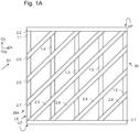
- Fig. 1A shows an exemplary wood-based load-bearing panel 28A for a construction system, as seen along a view normal to a plane Oxy.
- the panel 28A comprises a first ply 1 and a second ply 2 superimposed on one another along a direction normal to the plane Oxy.
- the plane Oxy is arranged parallel to a substantially vertical direction Oy.
- substantially vertical(ly) refers to an orientation of 10 degrees or less from aplomb.
- substantially horizontal(ly) refers to an orientation of at least 80 and at most 100 degrees from aplomb.
- the first ply 1 comprises a first wood-based strip 1.1 and a second wood-based strip 1.2.
- the first strip 1.1 of the first ply 1 is located at a left end LE of the panel 28A, as viewed normal to the plane Oxy.
- the first strip 1.1 of the first ply 1 is oriented in the substantially vertical direction Oy when the panel 28A is in use in a construction system.
- the first strip 1.1 of the first ply 1 has a length (as measured in the plane Oxy) identical (allowing for manufacturing tolerances of the panel and the strip) to the distance from a lower end LO of the panel 28A to an upper end UP of the panel 28.
- the first strip 1.1 of the first ply 1 may have a width of 100 mm (millimeters) or more and 250 mm or less, as measured in the plane Oxy perpendicular to the substantially vertical direction Oy. However, other widths are contemplated.
- Remarks for the first strip 1.1 of the first ply 1 apply to the second strip 1.2 of the first ply 1, except that the second strip 1.2 of the first ply is located at a right end RI of the panel 28A, as viewed normal to the plane Oxy.
- FIG. 1A shows the second strip 1.2 of the first ply 1 as having a width (as measured as for the first strip 1.1 of the first ply 1) that is identical (allowing for manufacturing tolerances of the strips) to the width of the first strip 1.1 of the first ply 1, it is also contemplated for two given strips of the first ply 1 to have different widths from one another.
- the first ply 1 may comprise a third wood-based strip 1.3 intermediate the first 1.1 and second 1.2 strips of the first ply 1, and is offset from both the first 1.1 and second 1.2 strips of the first ply 1 in a substantially horizontal direction Ox when the panel 28A is in use in the construction system.
- the third strip 1.3 of the first ply 1 is oriented in the substantially vertical direction Oy when the panel 28A is in use in the construction system.
- the third strip 1.3 of the first ply 1 may have a length identical (allowing for manufacturing tolerances of the strips) to that of the first strip 1.1 of the first ply 1.
- Fig. 1A shows the third strip 1.3 of the first ply 1 as having an identical (allowing for manufacturing tolerances of the strips) width to the first 1.1 and/or second 1.2 strip(s) of the first ply 1, it is contemplated that any given strip of the first ply 1 intermediate the first 1.1 and second 1.2 strips of the first ply 1 have a different width from the first 1.1 and/or second 1.2 strip(s) of the first ply 1.
- the first ply 1 may even comprise multiple wood-based strips oriented substantially vertically at positions intermediate the first 1.1 and second 1.2 strips of the first ply 1 and offset therefrom in the substantially horizontal direction Ox when the panel 28A is in use in the construction system.
- Fig. 1A shows the first ply 1 as having a fourth wood-based strip 1.4 and a fifth wood-based strip 1.5, each offset in the substantially horizontal direction Ox from the lower-numbered strips of the first ply 1 and intermediate the first 1.1 and second 1.2 strips of the first ply 1.
- Fig. 1A shows the strips 1.3, 1.4, 1.5 of the first ply 1 intermediate the first 1.1 and second 1.2 strips of the first ply 1 as having widths (as measured for the first strip 1.1 of the first ply 1) that are identical (allowing for manufacturing tolerances of the strips) to one another, it is also contemplated that two or more strips 1.3, 1.4, 1.5 of the first ply 1 intermediate the first 1.1 and second 1.2 strips of the first ply 1 have differing widths from one another.
- Increasing the number of strips of the first ply 1 intermediate the first 1.1 and second 1.2 strips of the first ply 1 may increase the ability of the panel 28A to support vertical loads.
- the second ply 2 is adjacent to the first ply 1 and comprises a first wood-based strip 2.1, a second wood-based strip 2.2, and a third wood-based strip 2.3.
- the first strip 2.1 of the second ply 2 is disposed at the lower end LO of the panel 28A.
- the first strip 2.1 of the second ply 2 is oriented in a substantially horizontal direction Ox when the panel 28A is in use in the construction system.
- the first strip 2.1 of the second ply 2 has a length (as measured in the plane Oxy along the substantially horizontal direction Ox) identical (allowing for manufacturing tolerances of the panel and the strip) to the distance from the left end LE of the panel 28A to the right end RI of the panel 28A.
- the first strip 2.1 of the second ply 2 has a width (as measured in the plane Oxy perpendicular to the substantially horizontal direction Ox) that is identical (allowing for manufacturing tolerances of the strips) to that of the first strip 1.1 of the first ply 1.
- a width as measured in the plane Oxy perpendicular to the substantially horizontal direction Ox
- other widths are contemplated.
- the first strip 2.1 of the second ply 2 is attached to the first 1.1 and second 1.2 strips of the first ply 1 by attachment means.
- the same may be true when the first ply 1 includes one or more substantially vertically oriented strips 1.3, 1.4, 1.5 intermediate the first 1.1 and second 1.2 strips of the first ply 1.
- Remarks for the first strip 2.1 of the second ply 2 apply to the second strip 2.2 of the second ply 2, except that the second strip 2.2 of the second ply 2 is disposed at the upper end UP of the panel 28A.
- the second strip 2.2 of the second ply 2 may have a width (as measured as for the first strip 2.1 of the second ply 2) that is identical (allowing for manufacturing tolerances of the strips) to the width of the first strip 2.1 of the second ply 2.
- a width as measured as for the first strip 2.1 of the second ply 2
- two given strips of the second ply 2 may have different widths from one another.
- the third strip 2.3 of the second ply 2 is oriented in a first direction D1 within the plane Oxy, different from the substantially horizontal direction Ox and the substantially vertical direction Oy.
- the first direction D1 defines an acute angle with respect to the substantially vertical Oy direction of 30 degrees or more to 60 degrees or less.
- other ranges for the angle defined by D1 are also contemplated, such as 30 degrees or more to 55 degrees or less, 30 degrees or more to 50 degrees or less, 30 degrees or more to 48 degrees or less, 30 degrees or more to 45 degrees or less, 35 degrees or more to 60 degrees or less, 35 degrees or more to 55 degrees or less, 35 degrees or more to 50 degrees or less, 35 degrees or more to 48 degrees or less, 35 degrees or more to 45 degrees or less, 40 degrees or more to 60 degrees or less, 40 degrees or more to 55 degrees or less, 40 degrees or more to 50 degrees or less, 40 degrees or more to 48 degrees or less, 40 degrees or more to 45 degrees or less, 42 degrees or more to 60 degrees or less, 42 degrees or more to 55 degrees or less, 42 degrees or more to 50 degrees or less, 42 degrees or more to 48 degrees or less, 42 degrees or more to 45 degrees or less, 45 degrees or more to 60 degrees or less, 45 degrees or more to
- the third strip 2.3 of the second ply 2 is attached to at least two strips of the first 1 and/or second 2 ply (plies) by attachment means.
- the third strip 2.3 of the second ply 2 is offset from a position where the first strip of the first ply and the second strip of the second ply attached to each other, and from a position where the second strip of the first ply and the first strip of the second ply are attached to each other, as considered along a direction within plane Oxy and perpendicular to the first direction D1.
- the third strip 2.3 of the second ply 2 is attached to the first 1.1 and second 1.2 strips of the first ply 1 by attachment means.
- the third strip 2.3 of the second ply 2 may increase the ability of the panel 28A to support shear loads within the plane Oxy and/or bending loads within the plane Oxy.
- Fig. 1A illustrates that the width of the third strip 2.3 of the second ply 2 may be identical (allowing for manufacturing tolerances of the strips) to the width of the first 2.1 and/or second 2.2 strip(s) of the second ply 2, it is also contemplated that the width of the third strip 2.3 of the second ply 2 (as measured in the plane Oxy and perpendicular to the first direction D1) be different from the width(s) of first 2.1 and/or second 2.2 strip(s) of the second ply 2.
- the second ply 2 may comprise multiple wood-based strips oriented along the first direction D1.
- the panel visible in Fig. 1A includes a fourth strip 2.4 arranged along the first direction D1 and offset from the position at which the first strip of the first ply and the second strip of the second ply are attached to each other, the position at which the second strip of the first ply and the first strip of the second ply are attached to each other, and the third strip 2.3 of the second ply 2, as considered along the direction in plane Oxy perpendicular to the first direction D1.
- the second ply 2 may even comprise a fifth strip 2.5, a sixth strip 2.6, a seventh strip 2.7, an eighth strip 2.8, and a ninth strip 2.9, each offset from one another, from the position at which the first strip of the first ply and the second strip of the second ply are attached to each other, and from the position at which the second strip of the first ply and the first trip of the second ply are attached to each other, as considered along the direction in plane Oxy perpendicular to the first direction D1.
- seven such strips 2.3, 2.4, 2.5, 2.6, 2.7, 2.8, 2.9 are visible in Fig. 1A , it is contemplated when multiple such strips are present to have as few as two, three, four, five or six, or even to have eight or more strips so oriented and offset with respect to each other and these positions within the second ply 2.
- the second ply 2 comprises multiple strips oriented along the first direction D1
- said strips may have identical (allowing for manufacturing tolerances of the strips) widths to one another or may vary from one such strip to the other.
- one of said strips 2.4, 2.5, 2.6, 2.7, 2.8, 2.9 of the second ply 2 may be wider or narrower than the third strip 2.3 of the second ply 2.
- Increasing the number of strips in the second ply 2 oriented along the first direction D1 may increase the panel's ability to support shear loads within the plane Oxy and/or bending loads within the plane Oxy.
- the number of strips 2.3, 2.4, 2.5, 2.6, 2.7, 2.8, 2.9 in the second ply 2 oriented along the first direction D1 may be independent from the number of strips 1.1, 1.2, 1.3, 1.4, 1.5 in the first ply 1 oriented along the substantially vertical direction Oy.
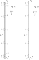
- Fig. 1B shows the panel of Fig. 1A as viewed from lower end thereof.
- the first strip 1.1 of the first ply 1 may have a thickness, as measured perpendicular to the plane Oxy, of 25 mm (millimeters) or more to 40 mm or less, of 30 mm or more to 40 mm or less, of 35 mm or more to 40 mm or less, of 40 mm or more to 45 mm or less, of 40 mm or more to 50 mm or less, of 40 mm or more to 55 mm or less, or of 40 mm or more to 60 mm or less.
- a thickness as measured perpendicular to the plane Oxy, of 25 mm (millimeters) or more to 40 mm or less, of 30 mm or more to 40 mm or less, of 35 mm or more to 40 mm or less, of 40 mm or more to 45 mm or less, of 40 mm or more to 50 mm or less, of 40 mm or more to 55 mm or less, or of 40 mm or more to 60 mm or less.
- other thicknesses are contemplated.
- Fig. 1B shows the first strip 2.1 of the second ply 2 as having an identical (allowing for manufacturing tolerances of the strips) thickness (as measured for the strips 1.1, 1.2, 1.3, 1.4, 1.5 of the first ply 1) to the strips 1.1, 1.2, 1.3, 1.4, 1.5 of the first ply 1, it is contemplated that the strips of the second ply 2 differ in thickness from the strips of the first ply 1.
- the panel comprise a third ply superimposed in series with the first 1 and second 2 plies along the direction normal to the plane Oxy such that the second ply 2 is intermediate the first 1 and third plies.
- the strips of the second ply 2 have an identical (allowing for tolerances in manufacturing of the strips) thickness to one another.
- An example of such a panel 28B is illustrated in Fig. 1C , as viewed from a lower end thereof.
- Strips of the second ply 2 that are attached to the first 1.1 and/or second 1.2 strip(s) of the first ply 1 are also attached respectively to the first 3.1 and/or second 3.2 strip(s) of the third ply 3 by attachment means.
- Providing the third ply 3 may increase the overall rigidity of the panel 28B.
- the first strip 3.1 of the third ply 3 may have a width (as measured for the first strip 1.1 of the first ply 1) that is identical (allowing for manufacturing tolerances of the strips) to that of the first strip 1.1 of the first ply 1. However, it is also contemplated for the widths of the first strips 1.1, 3.1 of the first 1 and third 3 plies to differ from one another.
- the first strip 3.1 of the third ply 3 may cooperate with the first strip 1.1 of the first ply 1 to stabilize the strips of the second ply 2 to which the first strips 1.1, 3.1 of the first 1 and third 3 plies are attached.
- the second strip 3.2 of the third ply 3 may have a width (as measured for the second strip 1.2 of the first ply 1) that is identical (allowing for manufacturing tolerances of the strips) to that of the second strip 1.2 of the first ply 1. However, it is also contemplated for the widths of the second strips 1.2, 3.2 of the first 1 and third 3 plies to differ from one another.
- the second strip 3.2 of the third ply 3 may cooperate with the second strip 1.2 of the first ply 1 to stabilize the strips of the second ply 2 to which the second strips 1.2, 3.2 of the first 1 and third 3 plies are attached.
- the third ply is shown in Fig. 1C as having as many substantially vertically oriented strips intermediate the first and second strips of the third ply as the first ply has intermediate its first and second strips, the presence or quantity of substantially vertically oriented strips 3.3, 3.4, 3.5 of the third ply 3 intermediate the first 3.1 and second 3.2 strips of the third ply 3 is independent of the presence or quantity of substantially vertically oriented strips 1.3, 1.4, 1.5 of the first ply 1 intermediate the first 1.1 and second 1.2 strips of the first ply 1.
- any given substantially vertically oriented strip 3.3, 3.4, 3.5 of the third ply 3 intermediate the first 3.1 and second 3.2 strips of the third ply 3 be independent from that of any substantially vertically oriented strip 1.3, 1.4, 1.5 of the first ply 1 intermediate the first 1.1 and second strips 1.2 of the first ply 1.
- any given - or even each - substantially vertically oriented strip 3.3, 3.4, 3.5 of the third ply 3 intermediate the first 3.1 and second 3.2 strips of the third ply 3 may be superimposed on a corresponding substantially vertically oriented strip 1.3, 1.4, 1.5 of the first ply 1 intermediate the first 1.1 and second 1.2 strips of the first ply 1, as seen in the direction normal to the plane Oxy.
- Increasing the number of substantially vertically oriented strips in the third ply 3 may increase stabilization of the second ply 2.
- any strip of the second ply 2 in contact with a strip of the third ply 3 be attached to said strip of the third ply 3 with attachment means.
- Fig. 1C shows the strips of third ply 3 as having an identical (allowing for tolerances in manufacturing of the strips) thickness (as measured for the strips of the first ply 1) to the strips of the first ply 1, it is also contemplated for the strips of the first 1 and third 3 plies to differ from one another.
- the panel 28B may even comprise a fourth ply 4 arranged in series with the first 1, second 2, and third 3 plies along the direction normal to the plane Oxy so that the first ply 1 is intermediate the second 2 and fourth 4 plies.
- the strips of the first ply 1 have identical (allowing for tolerances in the manufacturing of the strips) thicknesses to one another.
- the thickness of any given strip within any given ply may be independent of the thickness of any given strip in any other ply.
- Increasing the number of plies 2, 4 with a strip oriented along the first direction D1 can further improve the ability of the panel 28B to support shear and/or bending loads in the plane Oxy.
- the positions of strips in the second 2 and fourth 4 plies oriented along the first direction D1 are independent from one another; however, it is contemplated for the third strips 2.3, 4.3 of the second 2 and fourth 4 plies to be superimposed on each other as viewed along the direction normal to the plane Oxy.
- the presence or quantity of multiple wood-based strips 4.3, 4.4, 4.5, 4.6, 4.7, 4.8, 4.9 in the fourth ply 4 oriented along the first direction D1 is independent from the presence or quantity of multiple strips 2.3, 2.4, 2.5, 2.6, 2.7, 2.8, 2.9 in the second ply 2 oriented along the first direction D1.
- the separation distance(s) between neighboring strips 4.3, 4.4, 4.5, 4.6, 4.7, 4.8, 4.9 oriented along the first direction D1 in the fourth ply 4 may be independent from the separation distance(s) between neighboring strips 2.3, 2.4, 2.5, 2.6, 2.7, 2.8, 2.9 oriented along the first direction D1 in the second ply 2.
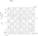
- Fig. 2 shows an exemplary wood-based load-bearing panel 28C for a construction system as viewed normal to the plane Oxy.
- the panel 28C comprises a first ply, a second ply, a third ply and a fourth ply.
- the fourth ply of Fig. 1C applies to the fourth ply of Fig. 2 , except that the first direction D1 is replaced with a second direction D2.
- the second direction D2 is within the plane Oxy and different from D1, the substantially horizontal direction Ox, and the substantially vertical direction Oy.
- the second direction D2 defines an acute angle with respect to the substantially vertical direction Oy of 30 degrees or more to 60 degrees or less.
- other ranges for the angle defined by D2 are also contemplated, such as 30 degrees or more to 55 degrees or less, 30 degrees or more to 50 degrees or less, 30 degrees or more to 48 degrees or less, 30 degrees or more to 45 degrees or less, 35 degrees or more to 60 degrees or less, 35 degrees or more to 55 degrees or less, 35 degrees or more to 50 degrees or less, 35 degrees or more to 48 degrees or less, 35 degrees or more to 45 degrees or less, 40 degrees or more to 60 degrees or less, 40 degrees or more to 55 degrees or less, 40 degrees or more to 50 degrees or less, 40 degrees or more to 48 degrees or less, 40 degrees or more to 45 degrees or less, 42 degrees or more to 60 degrees or less, 42 degrees or more to 55 degrees or less, 42 degrees or more to 50 degrees or less, 42 degrees or more to 48 degrees or less, 42 degrees or more to 45 degrees or less, 45 degrees or more to 60 degrees or less, 45 degrees or more to
- the acute angle defined by the second direction D2 and the substantially vertical direction Oy may be independent of the acute angle defined by the first direction D1 and the substantially vertical direction Oy.
- Fig. 2 illustrates that the width of the third strip 4.3 of the fourth ply may be identical (allowing for manufacturing tolerances of the strips) to the width of the first 4.1 and/or second 4.2 strip(s) of the fourth ply.
- the third 4.3 (and if present higher-numbered) strip(s) of the fourth ply is/are attached to at least two strips of the first and/or fourth ply (plies) by attachment means.
- the third strip 4.3 of the fourth ply is offset from a position where the first strips 1.1, 4.1 of the first and fourth plies are attached to each other, and from a position where the second strips 1.2, 4.2 of the first and fourth plies are attached to each other, as considered along a direction within plane Oxy and perpendicular to the second direction D2.
- the third strip 4.3 of the fourth ply is attached to the first 1.1 and second strips 1.2 of the first ply by attachment means.
- the third 2.3, 4.3 (and if present higher-numbered) strips of the second and fourth plies overlap one another as seen in the direction normal to the plane Oxy.
- the fourth ply comprises multiple strips 4.3, 4.4, 4.5, 4.6, 4.7, 4.8, 4.9 oriented along the second direction D2
- said strips 4.3, 4.4, 4.5, 4.6, 4.7, 4.8, 4.9 are offset from one another and from the position where the first strip 1.1 of the first ply and the second strip 4.2 of the fourth ply are attached to each other, and from the position where the second strip 1.2 of the first ply and the first trip 4.1 of the fourth ply are attached to each other, as considered along the direction within the plane Oxy and perpendicular to the second direction D2.
- the separation distance(s) between neighboring strips 4.3, 4.4, 4.5, 4.6, 4.7, 4.8, 4.9 oriented along the second direction D2 in the fourth ply may be independent from the separation distance(s) between neighboring strips 2.3, 2.4, 2.5, 2.6, 2.7, 2.8, 2.9 oriented along the first direction D1 in the second ply.
- the number of strips 4.3, 4.4, 4.5, 4.6, 4.7, 4.8, 4.9 of the fourth ply oriented along the second direction D2 may be independent from the number of strips 2.3, 2.4, 2.5, 2.6, 2.7, 2.8, 2.9 oriented along the first direction D1 in the second ply.
- the presence of strips in the second and fourth plies oriented along directions D1, D2 that are different from each other and from the substantially vertical Oy and substantially horizontal Ox directions may increase the ability of the panel 28C to support shear loads within the plane Oxy and/or bending loads within the plane Oxy by ensuring that such loads would solicit the strip(s) 2.3, 2.4, 2.5, 2.6, 2.7, 2.8, 2.9 of the second ply in tension while soliciting the strip(s) 4.3, 4.4, 4.5, 4.6, 4.7, 4.8, 4.9 of the fourth ply in compression, or vice versa.
- Fig. 2 shows the fourth ply having as many strips 4.3, 4.4, 4.5, 4.6, 4.7, 4.8, 4.9 oriented along the second direction D2 as the second ply has oriented along the first direction D1, the two quantities may be independent from one another.
- FIG. 2 shows separation distances (as measured in the plane Oxy and perpendicular to the second direction D2) between the strips 4.3, 4.4, 4.5, 4.6, 4.7, 4.8, 4.9 of the fourth ply oriented along the second direction D2 as being identical (allowing for tolerances in manufacturing of the strips and the panel 28C) to the separation distances (as measured in the plane Oxy and perpendicular to the first direction D1) between the strips 2.3, 2.4, 2.5, 2.6, 2.7, 2.8, 2.9 of the second ply oriented along the first direction D1
- the separation distance(s) between strips 4.3, 4.4, 4.5, 4.6, 4.7, 4.8, 4.9 of the fourth ply oriented along the second direction D2 is/are independent from the separation distance(s) between strips 2.3, 2.4, 2.5, 2.6, 2.7, 2.8, 2.9 of the second ply oriented along the first direction D1.
- Increasing the number of strips in the fourth ply oriented along the second direction D2 may increase the ability of the panel 28C to support shear loads within the plane Oxy and/or bending loads within the plane Oxy.
- the strips 2.3, 2.4, 2.5, 2.6, 2.7, 2.8, 2.9, 4.3, 4.4, 4.5, 4.6, 4.7, 4.8, 4.9 of the second and fourth plies oriented respectively along the first D1 and second D2 directions may overlap one another, as viewed along the direction normal to the plane Oxy. Due to the presence of the first ply intermediate the second and fourth plies, the strips of the second and fourth plies do not contact each other directly.
- the first ply comprises a substantially vertically oriented strip 1.3 intermediate the first 1.1 and second 1.2 strips of the first ply
- the third strips 1.3, 2.3, 4.3 of the first, second, and fourth plies are attached to one another by attachment means at a position intermediate their respective lengthwise extremities.
- attaching an intermediate substantially vertical strip 1.3 of the first ply to the third strips 2.3, 4.3 of the second and fourth plies at a position where the third strips 2.3, 4.3 of the second and fourth plies overlap one another, as seen along the direction normal to the plane Oxy may increase the overall rigidity of the panel 28C and/or improve stability of the first, second, and/or fourth plies.
- an intermediate substantially vertical strip 3.3 in the third ply so as to be attached to the third strip 2.3 of the second ply at the position where the third strip 2.3 of the second ply overlaps the third strip 4.3 of the fourth ply, for example to increase overall rigidity and/or stability further.
- the strips of the second and fourth plies oriented respectively along the first D1 and second D2 directions may overlap each other at multiple positions without contacting each other directly.
- the first ply includes multiple intermediate substantially vertically oriented strips 1.3, 1.4, 1.5, to provide said strips of the first ply 1 at some (or even all) of the positions where the a strip 2.3, 2.4, 2.5, 2.6, 2.7, 2.8, 2.9 of the second ply oriented along the first direction D1 overlaps a strip 4.3, 4.4, 4.5, 4.6, 4.7, 4.8, 4.9 of the fourth ply oriented along the second direction D2 as seen along the direction normal to the plane Oxy.
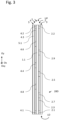
- Fig. 3 shows an exemplary wood-based load-bearing panel 28D for a construction system as viewed from a left end thereof.
- the panel includes a first ply 1, a second ply 2, a third ply 3, and a fourth ply 4 superimposed on each other in series along the direction normal to the plane Oxy as discussed for Fig. 2 .
- the panel 28D also includes a fifth ply 5, superimposed in series on the first 1, second 2, third 3, and fourth 4 plies along the direction normal to the plane Oxy, such that the fourth ply 4 is intermediate the first 1 and fifth 5 plies.
- the strips of the fourth ply 4 have identical (allowing for tolerances in manufacturing of the strips) thicknesses (as measured for the strips of the second ply) to one another.
- Remarks for the third ply 3 are applicable to the fifth ply 5, except that the strips of the fifth ply 5 are attached to strips of the fourth ply 4 - instead of to strips of the second ply 2 - by attachment means.
- any intermediate substantially vertical strip(s) 5.3, 5.4, 5.5 of the fifth ply 5 may be independent from the position(s) of intermediate substantially vertical strips 1.3, 1.4, 1.5, 3.3, 3.4, 3.5 of the first 1 and/or third 3 ply (plies), if present.
- a substantially vertically oriented strip 5.3, 5.4, 5.5 of the fifth ply 5 intermediate the first 5.1 and second 5.2 strips of the fifth ply 5 to be superimposed on a substantially vertically oriented strip 1.3, 1.4, 1.5 of the first ply 1 intermediate the first 1.1 and second 1.2 strips of the first ply 1 and/or on a substantially vertically oriented strip 3.3, 3.4, 3.5 of the third ply 3 intermediate the first 3.1 and second 3.2 strips of the third ply 3, as viewed along the direction normal to the plane Oxy.
- Providing the fifth ply 5 may increase the overall rigidity of the panel 28D and may help stabilize the fourth ply 4.
- Fig. 4 shows an exemplary wood-based load-bearing panel 28E in a perspective view.
- the panel 28E includes a first ply 1 and a second ply 2 superimposed on one another in the direction normal to the plane Oxy.
- the first ply 1 includes a first wood-based strip 1.1, a second wood-based strip 1.2, and a third wood-based strip 1.3.
- the second ply 2 includes a first wood-based strip 2.1, a second wood-based strip 2.2, a third wood-based strip 2.3, and a fourth wood-based strip 2.4.
- the third strip 2.3 of the second ply 2 is oriented along the first direction D1 and is attached to at least two strips of the first 1 and/or second 2 ply (plies) by attachment means so as to be offset from the position where the second strips 1.2, 2.2 of the first 1 and second 2 plies are attached to each other and from the position where the third strip 1.3 of the first ply 1 and the first strip 2.1 of the second ply 2 are attached to each other.
- the length of the third strip 2.3 of the second ply 2, as measured along the first direction D1, may be sufficient for the third strip 2.3 of the second ply 2 to be attached to the second 1.2 and third 1.3 strips of the first ply 1.
- the fourth strip 2.4 of the second ply 2 is oriented along the second direction D2 and is attached to at least two strips of the first 1 and/or second 2 ply (plies) by attachment means so as to be offset from the position where the first strip 1.1 of the first ply and the second strip 2.2 of the second ply 2 are attached to each other and from the position where the third strip 1.3 of the first ply 1 and the first strip 2.1 of the second ply 2.1 are attached to each other.
- the length of the fourth strip 2.4 of the second ply 2 may be sufficient for the fourth strip 2.4 of the second ply 2 to be attached to the first 1.1 and third 1.3 strips of the first ply 1.
- the second ply 2 may comprise two, three, four, five, six, seven, eight, or more strips 2.5, 2.7, 2.9, 2.11, 2.13, 2.15, 2.17 oriented along the first direction D1.
- Each of these strips 2.3, 2.5, 2.7, 2.9, 2.11, 2.13, 2.15, 2.17 of the second ply 2 is offset from its neighbor(s) in the second ply 2 in the direction in the plane Oxy and perpendicular to the first direction D1.
- the strips 2.3, 2.5, 2.7, 2.9, 2.11, 2.13, 2.15, 2.17 of the second ply 2 oriented in the first direction D1 are shown in Fig.
- a given strip of the second ply 2 oriented along the first direction D1 it is contemplated for a given strip of the second ply 2 oriented along the first direction D1 to have a different separation distance from one of its neighboring strips in the second ply 2 oriented along the first direction D1 than from another of its neighboring strips in the second ply 2 oriented along the first direction D1.
- the second ply 2 may comprise two, three, four, five, six, seven, eight, or more strips 2.6, 2.8, 2.10, 2.12, 2.14, 2.16, 2.18 oriented along the second direction D2.
- Each of these strips 2.4, 2.6, 2.8, 2.10, 2.12, 2.14, 2.16, 2.18 of the second ply 2 is offset from its neighbor(s) in the second ply 2 in the direction in the plane Oxy and perpendicular to the second direction D2.
- the strips 2.4, 2.6, 2.8, 2.10, 2.12, 2.14, 2.16, 2.18 of the second ply 2 oriented in the second direction D2 are shown in Fig.
- a given strip of the second ply 2 oriented along the second direction D2 to have a different separation distance from one of its neighboring strips in the second ply 2 oriented along the second direction D2 than from another of its neighboring strips in the second ply 2 oriented along the second direction D2.
- Fig. 4 shows the strips 2.4, 2.6, 2.8, 2.10, 2.12, 2.14, 2.16, 2.18 oriented along the second direction D2 in the second ply 2 as having separation distances, as measured in the plane Oxy and perpendicular to the second direction D2, which are equivalent (allowing for tolerances in manufacturing of the strips and the panel) to separation distances between the strips 2.3, 2.5, 2.7, 2.9, 2.11, 2.13, 2.15, 2.17 oriented along the first direction D1 in the second ply 2, as measured in the plane Oxy and perpendicular to the first direction D1
- separation distances for strips 2.4, 2.6, 2.8, 2.10, 2.12, 2.14, 2.16, 2.18 of the second ply 2 oriented along the second direction D2 differ from separation distances for strips 2.3, 2.5, 2.7, 2.9, 2.11, 2.13, 2.15, 2.17 of the second ply 2 oriented along the first direction D1.
- the number of strips in the second ply 2 oriented along the second direction D2 may be independent from the number of strips in the second ply 2 oriented along the first direction D1.
- any strip of the second ply 2 oriented along the first direction D1 comes into contact with any strip of the second ply 2 oriented along the second direction D2
- said strips of the second ply 2 are attached to each other by attachment means.
- the third 2.3 and fourth 2.4 strips of the second ply 2 are attached to one another at a position overlapped by the third strip 1.3 of the first ply 1, as viewed along the direction normal to the plane Oxy.
- the third strip 1.3 of the first ply 1 is thus attached to lengthwise extremities of the third 2.3 and fourth strips 2.4 of the second ply 2.
- Fig. 4 shows the first 1.2 and second 1.2 strips of the first ply 1 being arranged symmetrically with respect to the third strip 1.3 of the first ply 1, it is contemplated that the third strip 1.3 of the first ply 1 be closer to the first strip 1.1 of the first ply 1 than to the second strip 1.2 of the first ply 1, or vice versa.
- Fig. 4 shows the first ply 1 as having seven substantially vertically oriented wood-based strips 1.3, 1.4, 1.5, 1.6, 1.7, 1.8, 1.9 intermediate the first 1.1 and second 1.2 strips of the first ply 1, it is contemplated that the panel 28E may have two, three, four, five, six, or eight or more substantially vertically oriented strips 1.3, 1.4, 1.5, 1.6, 1.7, 1.8, 1.9 intermediate the first 1.1 and second 1.2 strips of the first ply 1.
- Each substantially vertical strip 1.3, 1.4, 1.5, 1.6, 1.7, 1.8, 1.9 of the first ply 1 arranged intermediate the first 1.1 and second 1.2 strips of the first ply 1 is attached by attachment means to each strip of the second ply 2 said intermediate substantially vertical strip 1.3, 1.4, 1.5, 1.6, 1.7, 1.8, 1.9 of the first ply 1 comes into contact.
- the panel 28E may comprise a third ply 3 superimposed on the first 1 and second 2 plies in the direction normal to the plane Oxy such that the second ply 2 is intermediate the first 1 and third 3 plies.
- the third ply 3 includes first 3.1 and second 3.2 wood-based strips. Remarks for the first 1.1 and second 1.2 strips of the first ply 1 apply respectively to the first 3.1 and second 3.2 strips of the third ply 3.
- the third ply 3 may include one or more substantially vertically oriented wood-based strip(s) 3.3, 3.4, 3.5, 3.6, 3.7, 3.8, 3.9 intermediate the first 3.1 and second 3.2 strips of the third ply 3, to which remarks for strips 1.3, 1.4, 1.5, 1.6, 1.7, 1.8, 1.9 of the first ply 1 that are intermediate of the first 1.1 and second 1.2 strips of the first ply 1 may be applicable.
- the panel 28E may comprise a fourth ply 4 superimposed on the first 1, second 2, and third 3 plies as explained for Fig. 1C .
- the strips of the first ply 1 have identical (allowing for tolerances in manufacturing of the strips) thicknesses to one another.
- Remarks for the second ply 2 may apply to the fourth ply 4, so that the third strip 4.3 of the fourth ply 4 (and any other strip(s) of the fourth ply 4 oriented along the first direction D1, if present) is/are arranged closer than the third strip 1.3 of the first ply 1 to the first strip 1.1 of the first ply 1, and the fourth strip 4.4 of the fourth ply 4 (and any other strip(s) of the fourth ply 4 oriented along the second direction D2, if present) is/are arranged closer than the third strip 1.3 of the first ply 1 to the second strip 1.2 of the first ply 1.
- the fourth ply 4 may differ from the second ply 2 in that the third strip 4.3 of the fourth ply 4 (and any other strip(s) of the fourth ply 4 oriented along the first direction D1, if present) is/are arranged closer than the third strip 1.3 of the first ply 1 to the second strip 1.2 of the first ply 1, and the fourth strip 4.4 of the fourth ply 4 (and any other strip(s) of the fourth ply 4 oriented along the second direction D2, if present) is/are arranged closer than the third strip 1.3 of the first ply 1 to the first strip 1.1 of the first ply 1.
- each substantially vertical strip 1.3, 1.4, 1.5, 1.6, 1.7, 1.8, 1.9 of the first ply 1 arranged intermediate the first 1.1 and second 1.2 strips of the first ply 1 is attached by attachment means to each strip of the fourth ply 4 said intermediate substantially vertical strip 1.3, 1.4, 1.5, 1.6, 1.7, 1.8, 1.9 of the first ply 1 comes into contact.
- the panel 28E may comprise a fifth ply 5 superimposed in series on the first 1, second 2, third 3, and fourth 4 plies as explained for Fig. 3 .
- the strips of the fourth ply 4 have identical (allowing for tolerances in manufacturing of the strips) thicknesses (as measured for the strips of the second ply) to one another.
- any given strip of any of the foregoing panels 28A, 28B, 28C, 28D, 28E may be composed of multiple wood-based elements joined together.
- the elements may be joined together in the lengthwise direction of the strip. Additionally or alternatively, the elements may be joined together in the width and/or thickness direction(s) of the strip.
- elements may be joined together in the lengthwise direction of the strip by means of one or more finger joints.
- elements may be joined together in the width and/or thickness direction(s) of the strip by means of one or more mechanical fasteners (nail/s screw/s, staple/s, clamp/s, or combinations thereof), one or more adhesives, or combinations thereof (e.g. "screw-gluing" whereby a mechanical fastener compresses adhered elements together).
- first and/or second strips of a given odd-numbered ply 1, 3, 5 with a greater width than that of a substantially vertically oriented strip 1.3, 1.4, 1.5, 1.6, 1.7, 1.8, 1.9, 3.3, 3.4, 3.5, 3.6, 3.7, 3.8, 3.9, 5.3, 5.4, 5.5, 5.6, 5.7, 5.8, 5.9 intermediate the first 1.1, 3.1, 5.1 and second 1.2, 3.2, 5.2 strips of said odd-numbered ply 1, 3, 5.
- first 1.1, 3.1, 5.1 and second 1.2, 3.2, 5.2 strips of each odd-numbered ply 1, 3, 5 are each composed of multiple wood-based elements 1.1A, 1.1B, 1.2A, 1.2B, 3.1A, 3.1B, 3.2A, 3.2B, 5.1A, 5.1B, 5.2A, 5.2B joined together in the width directions of the strips 1.1, 1.2, 3.1, 3.2, 5.1, 5.2.
- the third strip 2.3, 4.3 of a given even-numbered ply 2, 4 with a different width (e.g. greater or less) than that of the first and/or second strip(s) of said even-numbered ply.
- the attachment means used for attaching strips together in any of the foregoing panel the first strip of the second ply to the first and second strips of the first ply may include those disclosed in P01, P03, and/or P07, each incorporated herein by reference to the fullest extent permitted under local patent law.
- the attachment means may include adhesive, one or more nails, one or more screws, one or more clamps, one or more staples, or combinations thereof.
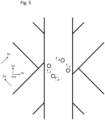
- Fig. 5 shows a detail view of an exemplary attachment means. Strips of adjacent plies are attached to one another directly; strips of non-adjacent plies are attached to one another indirectly by way of direct attachment to those of one or more adjacent plies.
- a given panel may have the same attachment means at all positions where one strip is attached to another within the panel.
- attachment means used within a given panel vary from one position to another, based on the orientations of the strips of the panel that are attached to one another at said position.
- the attachment means used to attach a strip of the intermediate ply to a strip of one of the neighboring plies may be offset (for example angularly) with respect to the attachment means used to attach the same strip of the intermediate ply to a strip of the other of the neighboring plies.
- the attachment means used to connect the intermediate ply's strip both of its neighboring plies' strips include hardware (e.g. screws, bolts, nails, staples, clamps).
- the hardware elements of the two attachment means may be offset from one another so as not to interfere with each other.
- the fasteners represented using solid circles
- the fasteners represented using dashed circles
- the fasteners represented using dashed circles
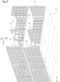
- Fig. 6 shows an exemplary construction system 8 with a façade 9 thereof highlighted.
- the façade 9 may be provided using panels as disclosed in P01, P02, P03, P04, P05, P06, and/or P07, each incorporated herein by reference to the fullest extent permitted by local patent law, or using any conventional panels.
- construction system 8 comprises two or more floors 10, 11, 12, 13, 14, 15, 16 above ground level, wind loading of the construction system 8 can become significant and introduce substantial shear loading into structural walls of the construction system 8.
- the construction system 8 comprises shear walls made of panels 28A, 28B, 28C, 28D, 28E as disclosed earlier herein. Their members oriented along the first D1 - and where present second D2 - direction(s) allow the panels 28A, 28B, 28C, 28D, 28E to undergo negligible deformation under shear loads.
- Fig. 7 shows the construction system of Fig. 6 with shear walls 101, 102, 103, 104, 105, 106, 107, 108, 109, 110 thereof highlighted.
- Each shear wall 101, 102, 103, 104, 105, 106, 107, 108, 109, 110 is made of a series of panels 28 arranged within a common plane Oxy and superimposed on one another in the substantially vertical direction Oy when in use in the construction system 8.
- Each shear wall 101, 102, 103, 104, 105, 106, 107, 108, 109, 110 contains as many panels 28 in the substantially vertical direction Oy as there are floors 10, 11, 12, 13, 14, 15, 16 from the foundation of the construction system 8 to the top floor of the construction system at the shear wall's position therein, inclusive.
- the construction system 8 may include multiple shear walls 101, 102, 103, 104, 105, 106, 107, 108, 109, 110 arranged parallel, perpendicularly, and/or obliquely to one another, and connected to one another.
- the construction system 8 visible in Fig. 6 and Fig. 7 may be a building in which the roof has yet to be installed, for example.
- each shear wall 101, 102, 103, 104, 105, 106, 107, 108, 109, 110 will extend from the roof at the shear wall's position within the building, down to the building's foundation.
- Fig. 8 shows an exemplary construction system with an interior wall thereof highlighted.
- the construction system 20 contains a lower level, a middle level, and an upper level arranged consecutively in series in the substantially vertical direction Oy.
- the upper level can be considered to be a roof or another storey of the construction system.
- the lower level is bounded by a floor of the lower level, not represented for clarity purposes, and a ceiling 25 of the lower level.
- the floor of the lower level can be considered to be a foundation, or a storey providing adequate structural support for the layout of the lower level.
- the ceiling 25 of the lower level is arranged over the floor of the lower level in the substantially vertical direction Oy.
- the lower level includes left 22 and right 21 load-bearing walls respectively supporting left and right sides of the ceiling 25 of the lower level.
- the left 22 and right 21 load-bearing walls of the lower level extend from the floor to the lower level to the ceiling 25 of the lower level so that substantially vertical loads from the ceiling 25 of the lower level may be transmitted therethrough to the floor of the lower level.
- the ceiling 25 of the lower level also serves as the floor of the middle level.
- the middle level is bounded by the floor 25 of the middle level and the ceiling 29 of the middle level.
- the ceiling of the middle level 29 can be considered to be the lowest portion of the upper level for the purposes of the present disclosure.
- the ceiling 29 of the middle level is arranged over the floor 25 of the middle level in the substantially vertical direction Oy.
- the middle level includes left 27 and right 26 load-bearing walls respectively supporting left and right sides of the ceiling 29 of the middle level.
- the left 27 and right 26 load-bearing walls of the middle level extend all of the way from the floor 25 of the middle level to the ceiling 29 of the middle level so that substantially vertical loads from the ceiling 29 of the middle level may be transmitted therethrough to the floor 25 of the middle level.
- the left 27 and right 26 load-bearing walls of the middle level are superimposed in series along the substantially vertical direction Oy with the floor 25 of the middle level and the respective left 22 and right 21 load-bearing walls of the lower level.
- the distance between the left 22 and right 21 load-bearing walls of the lower level is large enough that the ceiling 25 of the lower level needs support at a position intermediate (typically halfway between) the left 22 and right 21 load-bearing walls. Typically, such support would be provided by means of an intermediate load-bearing wall.
- no load-bearing wall is present in the lower level between a first column 23 of the lower level (visible in the foreground) and a second column 24 of the lower level (visible in the background relative to the first column of the lower level).
- the ceiling 25 of the lower level (the floor of the middle level) is inadequately supported from below in a region extending from the first column 23 of the lower level to the second column 24 of the lower level.
- the region of the ceiling 25 of the lower level that is inadequately supported from below by load-bearing walls could be supported from below instead by providing a beam or a lintel, so as to support the ceiling of the lower level from below.
- such solutions are relatively resource-intensive and/or space-consuming, possibly so much so that they would be incompatible with the needs that the construction system 20 is intended to address (e.g. budget, space, aesthetics, etc.).
- the construction system 20 visible in Fig. 8 uses a load-bearing panel 28 according to the present disclosure.
- the panel's lower end is fixed to the floor 25 of the middle level, and the panel's upper end is fixed to the ceiling 29 of the middle level, such that the first and last strips of the first ply of the panel 28 are oriented in the substantially vertical direction Oy and superimposed respectively on the first 23 and second 24 columns of the lower level as seen along the substantially vertical direction Oy.
- the panel's one or more strips oriented along the first D1 and/or second D2 direction(s) allow the panel 28 to resist in-plane bending forces.
- the panel 28 is able to provide the needed support to the floor 25 of the middle level from above.
Landscapes
- Engineering & Computer Science (AREA)
- Architecture (AREA)
- Civil Engineering (AREA)
- Structural Engineering (AREA)
- Life Sciences & Earth Sciences (AREA)
- Wood Science & Technology (AREA)
- Rod-Shaped Construction Members (AREA)
Abstract
characterized in that the third strip (2.3) of the second ply (2) is oriented in a first direction (D1), within the plane (Oxy), which differs from the substantially horizontal direction (Ox) and the substantially vertical direction (Oy), and is attached to at least two of the first (1.1), second (1.2), and third (1.3) strips of the first ply (1) by attachment means. Building or construction system comprising same.
Description
- The present disclosure relates to the field of buildings, construction systems, and panels therefor, particularly those using wood-based structural members in load-bearing applications.
- Within the present disclosure, a "construction system" refers to a plurality of structural elements in structural cooperation with one another to define a space in which vertical and/or horizontal incursion and/or excursion of electromagnetic radiation, fluid, and/or one or more solids is limited or prevented. For example, a construction system is typically used to limit vertical and/or horizontal incursion and/or excursion of light, wind, precipitation, and/or animal life into and/or out of a space.
- Within the present disclosure, a "building" refers to a construction system defining an enclosed space.
- Application
PCT/EP2022/057658 - Such a panel offers a beneficial ratio of performance to material use, recyclability, and customizability to local vertical loading requirements within a building or construction system, and has already seen successful use in the context of buildings comprising three or fewer floors above ground level.
- However, a load-bearing panel may be subjected to significant non-vertical loads, depending on the geographic location of the construction system, the location of the panel within the construction system, and/or even on the number of floors above ground level in the construction system. Conventionally, addressing such non-vertical loading has required the use of panels that lack the advantages of the panels described in
PCT/EP2022/057658 - The inventor(s) have realized that a need exists for a wood-based load-bearing panel that is able to withstand the non-vertical loads that can be present in construction systems, while conserving at least some of the benefits of the panel in
PCT/EP2022/057658 - To that end, the inventor(s) provide a wood-based load-bearing panel for use in a construction system, the panel comprising a series of superimposed plies in a plane.
- A first ply of the series of plies may comprise first, second, and third wood-based strips, which are distributed along the first ply and which are oriented in a substantially vertical direction. The first and second strips of the first ply may be disposed at a left end and a right end of the panel, respectively. The third strip of the first ply may be intermediate the first and second strips of the first ply.
- A second ply of the series of plies, adjacent to the first ply, may comprise first, second, and third wood-based strips, which are distributed along the second ply. The first and second strips of the second ply may be oriented in a substantially horizontal direction, disposed at a lower end and an upper end of the panel, respectively, and attached to each of the first, second, and third strips of the first ply by attachment means.
- A third ply of the series of plies may be adjacent to the second ply such that the second ply is intermediate the first and third plies, and may comprise first and second wood-based strips which are arranged at the left and right ends of the panel, respectively, oriented in the substantially vertical direction, and attached to the first and second strips of the second ply by attachment means.
- The third strip of the second ply may be oriented in a first direction, within the plane, which differs from the substantially horizontal direction and the substantially vertical direction. The third strip of the second ply may be attached to at least two of the first, second, and third strips of the first ply by attachment means.
- By providing a strip oriented along the first direction, the panel presents strips oriented along the substantially vertical direction, the substantially horizontal direction, and oblique to the substantially horizontal and vertical directions. The panel may thus be better able to withstand loading in shear and/or in-plane bending than a panel composed entirely of strips oriented in the substantially horizontal and substantially vertical directions.
- An acute angle between the substantially vertical direction and the first direction is 45 degrees, or within an angular range. The angular range may be 30 degrees or more to 60 degrees or less, 30 degrees or more to 55 degrees or less, 30 degrees or more to 50 degrees or less, 30 degrees or more to 48 degrees or less, 30 degrees or more to 45 degrees or less, 35 degrees or more to 60 degrees or less, 35 degrees or more to 55 degrees or less, 35 degrees or more to 50 degrees or less, 35 degrees or more to 48 degrees or less, 35 degrees or more to 45 degrees or less, 40 degrees or more to 60 degrees or less, 40 degrees or more to 55 degrees or less, 40 degrees or more to 50 degrees or less, 40 degrees or more to 48 degrees or less, 40 degrees or more to 45 degrees or less, 42 degrees or more to 60 degrees or less, 42 degrees or more to 55 degrees or less, 42 degrees or more to 50 degrees or less, 42 degrees or more to 48 degrees or less, 42 degrees or more to 45 degrees or less, 45 degrees or more to 60 degrees or less, 45 degrees or more to 55 degrees or less, 45 degrees or more to 50 degrees or less, or 45 degrees or more to 48 degrees or less.
- Such angles, or angular ranges, may offer favorable compromises between shear strength of the panel, contact area between the first and second plies' strips, and the number of strips used in the second ply.
- The second ply may comprise an additional wood-based strip, offset from the third strip of the second ply, and oriented in a direction substantially parallel to the first direction of the third strip of the second ply. The additional strip may be attached to at least two of the first, second, and third strips of the first ply by attachment means.
- The panel may thus have multiple strips oriented along the first direction. A panel with multiple strips oriented along the first direction may offer improved resistance to shear loading and/or in-plane bending loads than a panel with only one strip oriented in the first direction.
- The additional strip of the second ply may be wider, as measured in the plane and perpendicular to the first direction, than the third strip of the second ply.
- When multiple strips oriented along the first direction are present in the second ply, their widths may vary from one strip oriented along the first direction to another.
- As a non-limiting example, such variability may increase customizability of the panel according to local performance needs imposed by the building/construction system.
- The third strip of the second ply may be attached to the first and third strips of the first ply. The second ply may comprise a fourth wood-based strip oriented in a second direction, differing from the substantially vertical direction, the substantially horizontal direction, and the first direction. The fourth strip of the second ply may be attached to the second and third strips of the first ply by attachment means.
- The third ply may comprise a third wood-based strip oriented in the substantially vertical direction, arranged intermediate the first and second strips of the third ply, and attached to the first and second strips of the second ply by attachment means.
- The panel may comprise a fourth ply adjacent the first or third ply such that said first or third ply is intermediate the second and fourth plies.
- The fourth ply may comprise first and second wood-based strips oriented in the substantially horizontal direction, disposed at the lower and upper ends of the panel, respectively, and attached to at least two of the substantially vertical strips of said first or third ply by attachment means.
- The fourth ply may comprise a third wood-based strip attached to at least two substantially vertical strips of said first or third ply by attachment means.
- The third strip of the fourth ply may be oriented in a direction substantially parallel to the first direction of the third strip of the second ply. Alternatively, the third strip of the fourth ply may be oriented in a second direction differing from the substantially vertical direction.
- The third strips of the second and fourth plies may each be attached to the third strip of the first ply by attachment means at a position intermediate their respective lengthwise extremities.
- The third strip of the fourth ply may be attached to each of the first, second, and third strips of the first ply by attachment means.
- Widths of the third strips of the second and fourth plies, as measured in the plane perpendicular to the direction(s) along which said third strips are oriented may be different from one another.
- The panel may comprise a fifth ply adjacent the fourth ply such that the fourth ply is intermediate the second and fifth plies. The fifth ply may comprise first and second wood-based strips oriented in the substantially vertical direction at left and right ends of the panel, respectively, each of the first and second strips of the fifth ply being attached to the first and second strips of the fourth ply by attachment means.
- The third strip of the second ply may be attached to each of the first, second, and third strips of the first ply by attachment means.
- The third ply may comprise a third wood-based strip oriented in the substantially vertical direction, arranged intermediate the first and second strips of the third ply, and attached to the first and second strips of the second ply by attachment means.
- The inventor(s) also propose a building or construction system comprising a panel as described earlier herein.
- The disclosure may be more completely understood in consideration of the following detailed description of aspects of the disclosure in connection with the accompanying drawings, in which:
-
Fig. 1A shows an exemplary wood-based load-bearing panel for a construction system along a view normal to a plane Oxy. -
Fig. 1B shows the panel ofFig. 1A as viewed from a lower end thereof. -
Fig. 1C shows an exemplary wood-based load-bearing panel for a construction system as viewed from a lower end thereof. -
Fig. 2 shows an exemplary wood-based load-bearing as viewed normal to the plane Oxy. -
Fig. 3 shows an exemplary wood-based load-bearing panel for a construction system as viewed from a left end thereof. -
Fig. 4 shows an exemplary wood-based load-bearing panel in a perspective view. -
Fig. 5 shows a detail view of an exemplary attachment means. -
Fig. 6 shows an exemplary construction system with a façade thereof highlighted. -
Fig. 7 shows the construction system ofFig. 7 with shear walls thereof highlighted. -
Fig. 8 shows an exemplary construction system. - The term "exemplary" is used in the sense of "example," rather than "ideal." While aspects of the disclosure are amenable to various modifications and alternative forms, specifics thereof have been shown by way of example in the drawings and will be described in detail. It should be understood, however, that the intention is not to limit aspects of the disclosure to the particular embodiment(s) described. On the contrary, the intention of this disclosure is to cover all modifications, equivalents, and alternatives falling within the scope of the disclosure.
- As used in this disclosure and the appended claims, the singular forms "a", "an", and "the" include plural referents unless the content clearly dictates otherwise. As used in this disclosure and the appended claims, the term "or" is generally employed in its sense including "and/or" unless the content clearly dictates otherwise.
- The following detailed description should be read with reference to the drawings. The detailed description and the drawings, which are not necessarily to scale, depict illustrative aspects and are not intended to limit the scope of the disclosure. The illustrative aspects depicted are intended only as exemplary.
- Although the terms "first," "second," etc. may be used herein to describe various panels, buildings, construction systems, levels, floors, ceilings, walls, roofs, strips, plies, layers, steps, elements, components, regions, layers, sections, and/or parameters, these panels, buildings, construction systems, levels, floors, ceilings, walls, roofs, strips, plies, layers, steps, elements, components, regions, layers, sections, and/or parameters should not be limited by these terms. These terms are only used to distinguish one panel, building, construction system, level, floor, ceiling, wall, roof, strip, ply, layer, step, element, component, region, layer, section, or parameter, from another panel, building, construction system, level, floor, ceiling, wall, roof, strip, ply, layer, step, element, component, region, layer, section, or parameter. Thus, a first panel, building, construction system, level, floor, ceiling, wall, roof, strip, ply, layer, step, element, component, region, layer, section, and/or parameter discussed herein could be termed a second panel, building, construction system, level, floor, ceiling, wall, roof, strip, ply, layer, step, element, component, region, layer, section, and/or parameter without departing from the teachings of the present inventive subject matter.
- Herein, "P01" stands for application
PCT/FR2017/052723 PCT/EP2018/054936 PCT/EP2018/071166 PCT/EP2021/025339 PCT/EP2021/025340 PCT/EP2022/052986 PCT/EP2022/057658 - Within the present disclosure, a panel may be considered to be "wood-based" when at least 15% of the global volume of the panel is occupied by wood. A strip or element may be considered wood to be "wood-based" when it has a composition of at least 50% wood by volume and/or by mass. As a non-limiting example, a wood-based strip may be made partially or entirely of a wood-polymer composite as disclosed in P06, incorporated herein by reference to the fullest extent permitted under local patent law.
-
Fig. 1A shows an exemplary wood-based load-bearing panel 28A for a construction system, as seen along a view normal to a plane Oxy. - The
panel 28A comprises afirst ply 1 and asecond ply 2 superimposed on one another along a direction normal to the plane Oxy. - When the
panel 28A is in use in a construction system, the plane Oxy is arranged parallel to a substantially vertical direction Oy. - As used in the present disclosure, "substantially vertical(ly)" refers to an orientation of 10 degrees or less from aplomb.
- As used in the present disclosure, "substantially horizontal(ly)" refers to an orientation of at least 80 and at most 100 degrees from aplomb.
- The
first ply 1 comprises a first wood-based strip 1.1 and a second wood-based strip 1.2. - The first strip 1.1 of the
first ply 1 is located at a left end LE of thepanel 28A, as viewed normal to the plane Oxy. - The first strip 1.1 of the
first ply 1 is oriented in the substantially vertical direction Oy when thepanel 28A is in use in a construction system. - The first strip 1.1 of the
first ply 1 has a length (as measured in the plane Oxy) identical (allowing for manufacturing tolerances of the panel and the strip) to the distance from a lower end LO of thepanel 28A to an upper end UP of thepanel 28. - The first strip 1.1 of the
first ply 1 may have a width of 100 mm (millimeters) or more and 250 mm or less, as measured in the plane Oxy perpendicular to the substantially vertical direction Oy. However, other widths are contemplated. - Remarks for the first strip 1.1 of the
first ply 1 apply to the second strip 1.2 of thefirst ply 1, except that the second strip 1.2 of the first ply is located at a right end RI of thepanel 28A, as viewed normal to the plane Oxy. - Although
Fig. 1A shows the second strip 1.2 of thefirst ply 1 as having a width (as measured as for the first strip 1.1 of the first ply 1) that is identical (allowing for manufacturing tolerances of the strips) to the width of the first strip 1.1 of thefirst ply 1, it is also contemplated for two given strips of thefirst ply 1 to have different widths from one another. - The
first ply 1 may comprise a third wood-based strip 1.3 intermediate the first 1.1 and second 1.2 strips of thefirst ply 1, and is offset from both the first 1.1 and second 1.2 strips of thefirst ply 1 in a substantially horizontal direction Ox when thepanel 28A is in use in the construction system. - The third strip 1.3 of the
first ply 1 is oriented in the substantially vertical direction Oy when thepanel 28A is in use in the construction system. - The third strip 1.3 of the
first ply 1 may have a length identical (allowing for manufacturing tolerances of the strips) to that of the first strip 1.1 of thefirst ply 1. - Although
Fig. 1A shows the third strip 1.3 of thefirst ply 1 as having an identical (allowing for manufacturing tolerances of the strips) width to the first 1.1 and/or second 1.2 strip(s) of thefirst ply 1, it is contemplated that any given strip of thefirst ply 1 intermediate the first 1.1 and second 1.2 strips of thefirst ply 1 have a different width from the first 1.1 and/or second 1.2 strip(s) of thefirst ply 1. - The
first ply 1 may even comprise multiple wood-based strips oriented substantially vertically at positions intermediate the first 1.1 and second 1.2 strips of thefirst ply 1 and offset therefrom in the substantially horizontal direction Ox when thepanel 28A is in use in the construction system. - For example,
Fig. 1A shows thefirst ply 1 as having a fourth wood-based strip 1.4 and a fifth wood-based strip 1.5, each offset in the substantially horizontal direction Ox from the lower-numbered strips of thefirst ply 1 and intermediate the first 1.1 and second 1.2 strips of thefirst ply 1. However, it is also contemplated to forego the fifth strip 1.5 of the first ply, or even to provide a sixth or further substantially vertical wood-based strip in thefirst ply 1 that is offset in the substantially horizontal direction Ox from the lower-numbered strips of thefirst ply 1 and intermediate the first 1.1 and second 1.2 strips of thefirst ply 1. - Remarks for the third strip 1.3 of the
first ply 1 apply to each strip(s) 1.4, 1.5 of thefirst ply 1 intermediate the first 1.1 and second 1.2 strips of thefirst ply 1. - Although
Fig. 1A shows the strips 1.3, 1.4, 1.5 of thefirst ply 1 intermediate the first 1.1 and second 1.2 strips of thefirst ply 1 as having widths (as measured for the first strip 1.1 of the first ply 1) that are identical (allowing for manufacturing tolerances of the strips) to one another, it is also contemplated that two or more strips 1.3, 1.4, 1.5 of thefirst ply 1 intermediate the first 1.1 and second 1.2 strips of thefirst ply 1 have differing widths from one another. - Increasing the number of strips of the
first ply 1 intermediate the first 1.1 and second 1.2 strips of thefirst ply 1 may increase the ability of thepanel 28A to support vertical loads. - The
second ply 2 is adjacent to thefirst ply 1 and comprises a first wood-based strip 2.1, a second wood-based strip 2.2, and a third wood-based strip 2.3. - The first strip 2.1 of the
second ply 2 is disposed at the lower end LO of thepanel 28A. - The first strip 2.1 of the
second ply 2 is oriented in a substantially horizontal direction Ox when thepanel 28A is in use in the construction system. - The first strip 2.1 of the
second ply 2 has a length (as measured in the plane Oxy along the substantially horizontal direction Ox) identical (allowing for manufacturing tolerances of the panel and the strip) to the distance from the left end LE of thepanel 28A to the right end RI of thepanel 28A. - As seen in
Fig. 1A , the first strip 2.1 of thesecond ply 2 has a width (as measured in the plane Oxy perpendicular to the substantially horizontal direction Ox) that is identical (allowing for manufacturing tolerances of the strips) to that of the first strip 1.1 of thefirst ply 1. However, other widths are contemplated. - The first strip 2.1 of the
second ply 2 is attached to the first 1.1 and second 1.2 strips of thefirst ply 1 by attachment means. The same may be true when thefirst ply 1 includes one or more substantially vertically oriented strips 1.3, 1.4, 1.5 intermediate the first 1.1 and second 1.2 strips of thefirst ply 1. - Remarks for the first strip 2.1 of the
second ply 2 apply to the second strip 2.2 of thesecond ply 2, except that the second strip 2.2 of thesecond ply 2 is disposed at the upper end UP of thepanel 28A. - As seen in
Fig. 1A , the second strip 2.2 of thesecond ply 2 may have a width (as measured as for the first strip 2.1 of the second ply 2) that is identical (allowing for manufacturing tolerances of the strips) to the width of the first strip 2.1 of thesecond ply 2. However, it is also contemplated for two given strips of thesecond ply 2 to have different widths from one another. - The third strip 2.3 of the
second ply 2 is oriented in a first direction D1 within the plane Oxy, different from the substantially horizontal direction Ox and the substantially vertical direction Oy. - The first direction D1 defines an acute angle with respect to the substantially vertical Oy direction of 30 degrees or more to 60 degrees or less. However, other ranges for the angle defined by D1 are also contemplated, such as 30 degrees or more to 55 degrees or less, 30 degrees or more to 50 degrees or less, 30 degrees or more to 48 degrees or less, 30 degrees or more to 45 degrees or less, 35 degrees or more to 60 degrees or less, 35 degrees or more to 55 degrees or less, 35 degrees or more to 50 degrees or less, 35 degrees or more to 48 degrees or less, 35 degrees or more to 45 degrees or less, 40 degrees or more to 60 degrees or less, 40 degrees or more to 55 degrees or less, 40 degrees or more to 50 degrees or less, 40 degrees or more to 48 degrees or less, 40 degrees or more to 45 degrees or less, 42 degrees or more to 60 degrees or less, 42 degrees or more to 55 degrees or less, 42 degrees or more to 50 degrees or less, 42 degrees or more to 48 degrees or less, 42 degrees or more to 45 degrees or less, 45 degrees or more to 60 degrees or less, 45 degrees or more to 55 degrees or less, 45 degrees or more to 50 degrees or less, or 45 degrees or more to 48 degrees or less.
- The third strip 2.3 of the
second ply 2 is attached to at least two strips of the first 1 and/or second 2 ply (plies) by attachment means. - The third strip 2.3 of the
second ply 2 is offset from a position where the first strip of the first ply and the second strip of the second ply attached to each other, and from a position where the second strip of the first ply and the first strip of the second ply are attached to each other, as considered along a direction within plane Oxy and perpendicular to the first direction D1. - As seen in
Fig. 1A , the third strip 2.3 of thesecond ply 2 is attached to the first 1.1 and second 1.2 strips of thefirst ply 1 by attachment means. - The third strip 2.3 of the
second ply 2 may increase the ability of thepanel 28A to support shear loads within the plane Oxy and/or bending loads within the plane Oxy. - Although
Fig. 1A illustrates that the width of the third strip 2.3 of thesecond ply 2 may be identical (allowing for manufacturing tolerances of the strips) to the width of the first 2.1 and/or second 2.2 strip(s) of thesecond ply 2, it is also contemplated that the width of the third strip 2.3 of the second ply 2 (as measured in the plane Oxy and perpendicular to the first direction D1) be different from the width(s) of first 2.1 and/or second 2.2 strip(s) of thesecond ply 2. - The
second ply 2 may comprise multiple wood-based strips oriented along the first direction D1. - For example, the panel visible in
Fig. 1A includes a fourth strip 2.4 arranged along the first direction D1 and offset from the position at which the first strip of the first ply and the second strip of the second ply are attached to each other, the position at which the second strip of the first ply and the first strip of the second ply are attached to each other, and the third strip 2.3 of thesecond ply 2, as considered along the direction in plane Oxy perpendicular to the first direction D1. - The
second ply 2 may even comprise a fifth strip 2.5, a sixth strip 2.6, a seventh strip 2.7, an eighth strip 2.8, and a ninth strip 2.9, each offset from one another, from the position at which the first strip of the first ply and the second strip of the second ply are attached to each other, and from the position at which the second strip of the first ply and the first trip of the second ply are attached to each other, as considered along the direction in plane Oxy perpendicular to the first direction D1. Although seven such strips 2.3, 2.4, 2.5, 2.6, 2.7, 2.8, 2.9 are visible inFig. 1A , it is contemplated when multiple such strips are present to have as few as two, three, four, five or six, or even to have eight or more strips so oriented and offset with respect to each other and these positions within thesecond ply 2. - When the
second ply 2 comprises multiple strips oriented along the first direction D1, said strips may have identical (allowing for manufacturing tolerances of the strips) widths to one another or may vary from one such strip to the other. For example, one of said strips 2.4, 2.5, 2.6, 2.7, 2.8, 2.9 of thesecond ply 2 may be wider or narrower than the third strip 2.3 of thesecond ply 2. - Increasing the number of strips in the
second ply 2 oriented along the first direction D1 may increase the panel's ability to support shear loads within the plane Oxy and/or bending loads within the plane Oxy. - The number of strips 2.3, 2.4, 2.5, 2.6, 2.7, 2.8, 2.9 in the
second ply 2 oriented along the first direction D1 may be independent from the number of strips 1.1, 1.2, 1.3, 1.4, 1.5 in thefirst ply 1 oriented along the substantially vertical direction Oy. -
Fig. 1B shows the panel ofFig. 1A as viewed from lower end thereof. - As a non-limiting example, the first strip 1.1 of the
first ply 1 may have a thickness, as measured perpendicular to the plane Oxy, of 25 mm (millimeters) or more to 40 mm or less, of 30 mm or more to 40 mm or less, of 35 mm or more to 40 mm or less, of 40 mm or more to 45 mm or less, of 40 mm or more to 50 mm or less, of 40 mm or more to 55 mm or less, or of 40 mm or more to 60 mm or less. However, other thicknesses are contemplated. - Although
Fig. 1B shows the first strip 2.1 of thesecond ply 2 as having an identical (allowing for manufacturing tolerances of the strips) thickness (as measured for the strips 1.1, 1.2, 1.3, 1.4, 1.5 of the first ply 1) to the strips 1.1, 1.2, 1.3, 1.4, 1.5 of thefirst ply 1, it is contemplated that the strips of thesecond ply 2 differ in thickness from the strips of thefirst ply 1. - It is also contemplated that the panel comprise a third ply superimposed in series with the first 1 and second 2 plies along the direction normal to the plane Oxy such that the
second ply 2 is intermediate the first 1 and third plies. In this case, the strips of thesecond ply 2 have an identical (allowing for tolerances in manufacturing of the strips) thickness to one another. An example of such apanel 28B is illustrated inFig. 1C , as viewed from a lower end thereof. - Remarks for the first 1 and second 2 plies discussed in connection with
Fig. 1A andFig. 1B apply respectively to the first 1 and second 2 plies of thepanel 28B ofFig. 1C . - Remarks for the
first ply 1 of thispanel 28B apply to thethird ply 3 of thispanel 28B. - Strips of the
second ply 2 that are attached to the first 1.1 and/or second 1.2 strip(s) of thefirst ply 1 are also attached respectively to the first 3.1 and/or second 3.2 strip(s) of thethird ply 3 by attachment means. - Providing the
third ply 3 may increase the overall rigidity of thepanel 28B. - The first strip 3.1 of the
third ply 3 may have a width (as measured for the first strip 1.1 of the first ply 1) that is identical (allowing for manufacturing tolerances of the strips) to that of the first strip 1.1 of thefirst ply 1. However, it is also contemplated for the widths of the first strips 1.1, 3.1 of the first 1 and third 3 plies to differ from one another. - The first strip 3.1 of the
third ply 3 may cooperate with the first strip 1.1 of thefirst ply 1 to stabilize the strips of thesecond ply 2 to which the first strips 1.1, 3.1 of the first 1 and third 3 plies are attached. - The second strip 3.2 of the
third ply 3 may have a width (as measured for the second strip 1.2 of the first ply 1) that is identical (allowing for manufacturing tolerances of the strips) to that of the second strip 1.2 of thefirst ply 1. However, it is also contemplated for the widths of the second strips 1.2, 3.2 of the first 1 and third 3 plies to differ from one another. - The second strip 3.2 of the
third ply 3 may cooperate with the second strip 1.2 of thefirst ply 1 to stabilize the strips of thesecond ply 2 to which the second strips 1.2, 3.2 of the first 1 and third 3 plies are attached. - Although the third ply is shown in
Fig. 1C as having as many substantially vertically oriented strips intermediate the first and second strips of the third ply as the first ply has intermediate its first and second strips, the presence or quantity of substantially vertically oriented strips 3.3, 3.4, 3.5 of thethird ply 3 intermediate the first 3.1 and second 3.2 strips of thethird ply 3 is independent of the presence or quantity of substantially vertically oriented strips 1.3, 1.4, 1.5 of thefirst ply 1 intermediate the first 1.1 and second 1.2 strips of thefirst ply 1. - It is contemplated that the position in the substantially horizontal direction Ox of any given substantially vertically oriented strip 3.3, 3.4, 3.5 of the
third ply 3 intermediate the first 3.1 and second 3.2 strips of thethird ply 3 be independent from that of any substantially vertically oriented strip 1.3, 1.4, 1.5 of thefirst ply 1 intermediate the first 1.1 and second strips 1.2 of thefirst ply 1. However, as seen inFig. 1C , any given - or even each - substantially vertically oriented strip 3.3, 3.4, 3.5 of thethird ply 3 intermediate the first 3.1 and second 3.2 strips of thethird ply 3 may be superimposed on a corresponding substantially vertically oriented strip 1.3, 1.4, 1.5 of thefirst ply 1 intermediate the first 1.1 and second 1.2 strips of thefirst ply 1, as seen in the direction normal to the plane Oxy. - Increasing the number of substantially vertically oriented strips in the
third ply 3 may increase stabilization of thesecond ply 2. - It is contemplated that any strip of the
second ply 2 in contact with a strip of thethird ply 3 be attached to said strip of thethird ply 3 with attachment means. - Although
Fig. 1C shows the strips ofthird ply 3 as having an identical (allowing for tolerances in manufacturing of the strips) thickness (as measured for the strips of the first ply 1) to the strips of thefirst ply 1, it is also contemplated for the strips of the first 1 and third 3 plies to differ from one another. - As shown in
Fig. 1C , thepanel 28B may even comprise afourth ply 4 arranged in series with the first 1, second 2, and third 3 plies along the direction normal to the plane Oxy so that thefirst ply 1 is intermediate the second 2 and fourth 4 plies. In this case, the strips of thefirst ply 1 have identical (allowing for tolerances in the manufacturing of the strips) thicknesses to one another. - While the strips within a given ply intermediate two other plies may have identical (allowing for tolerances in manufacturing of the strips) and uniform (allowing for tolerances in manufacturing of the strips) thicknesses (measured normal to the plane Oxy) to one another, the thickness of any given strip within any given ply may be independent of the thickness of any given strip in any other ply.
- Thus, with the possible exception of strips within the
second ply 2 having identical thicknesses do one another and being attached to strips of thethird ply 3, remarks for thesecond ply 2 apply to thefourth ply 4. - Increasing the number of
plies panel 28B to support shear and/or bending loads in the plane Oxy. - The positions of strips in the second 2 and fourth 4 plies oriented along the first direction D1 are independent from one another; however, it is contemplated for the third strips 2.3, 4.3 of the second 2 and fourth 4 plies to be superimposed on each other as viewed along the direction normal to the plane Oxy.
- The presence or quantity of multiple wood-based strips 4.3, 4.4, 4.5, 4.6, 4.7, 4.8, 4.9 in the
fourth ply 4 oriented along the first direction D1 is independent from the presence or quantity of multiple strips 2.3, 2.4, 2.5, 2.6, 2.7, 2.8, 2.9 in thesecond ply 2 oriented along the first direction D1. - If the
second ply 2 comprises multiple strips 2.3, 2.4, 2.5, 2.6, 2.7, 2.8, 2.9 oriented along the first direction D1, the separation distance(s) between neighboring strips 4.3, 4.4, 4.5, 4.6, 4.7, 4.8, 4.9 oriented along the first direction D1 in thefourth ply 4 may be independent from the separation distance(s) between neighboring strips 2.3, 2.4, 2.5, 2.6, 2.7, 2.8, 2.9 oriented along the first direction D1 in thesecond ply 2. -
Fig. 2 shows an exemplary wood-based load-bearing panel 28C for a construction system as viewed normal to the plane Oxy. - The panel 28C comprises a first ply, a second ply, a third ply and a fourth ply.
- Remarks for the first, second, and third plies of
Fig. 1C apply respectively to the first, second, and third plies ofFig. 2 . - Remarks for the fourth ply of
Fig. 1C apply to the fourth ply ofFig. 2 , except that the first direction D1 is replaced with a second direction D2. The second direction D2 is within the plane Oxy and different from D1, the substantially horizontal direction Ox, and the substantially vertical direction Oy. - The second direction D2 defines an acute angle with respect to the substantially vertical direction Oy of 30 degrees or more to 60 degrees or less. However, other ranges for the angle defined by D2 are also contemplated, such as 30 degrees or more to 55 degrees or less, 30 degrees or more to 50 degrees or less, 30 degrees or more to 48 degrees or less, 30 degrees or more to 45 degrees or less, 35 degrees or more to 60 degrees or less, 35 degrees or more to 55 degrees or less, 35 degrees or more to 50 degrees or less, 35 degrees or more to 48 degrees or less, 35 degrees or more to 45 degrees or less, 40 degrees or more to 60 degrees or less, 40 degrees or more to 55 degrees or less, 40 degrees or more to 50 degrees or less, 40 degrees or more to 48 degrees or less, 40 degrees or more to 45 degrees or less, 42 degrees or more to 60 degrees or less, 42 degrees or more to 55 degrees or less, 42 degrees or more to 50 degrees or less, 42 degrees or more to 48 degrees or less, 42 degrees or more to 45 degrees or less, 45 degrees or more to 60 degrees or less, 45 degrees or more to 55 degrees or less, 45 degrees or more to 50 degrees or less, or 45 degrees or more to 48 degrees or less.
- The acute angle defined by the second direction D2 and the substantially vertical direction Oy may be independent of the acute angle defined by the first direction D1 and the substantially vertical direction Oy.
- Although the width of the third strip 4.3 of the fourth ply may very well have a different width (as measured in the plane Oxy and perpendicular to the second direction D2) from the first 4.1 and/or second 4.2 strip(s) of the fourth ply,
Fig. 2 illustrates that the width of the third strip 4.3 of the fourth ply may be identical (allowing for manufacturing tolerances of the strips) to the width of the first 4.1 and/or second 4.2 strip(s) of the fourth ply. - If multiple strips 4.3, 4.4, 4.5, 4.6, 4.7, 4.8, 4.9 are present in the fourth ply oriented along the second direction D2, their widths may be identical to one another or vary from one such strip to another.
- The third 4.3 (and if present higher-numbered) strip(s) of the fourth ply is/are attached to at least two strips of the first and/or fourth ply (plies) by attachment means.
- The third strip 4.3 of the fourth ply is offset from a position where the first strips 1.1, 4.1 of the first and fourth plies are attached to each other, and from a position where the second strips 1.2, 4.2 of the first and fourth plies are attached to each other, as considered along a direction within plane Oxy and perpendicular to the second direction D2.
- As seen in
Fig. 2 , the third strip 4.3 of the fourth ply is attached to the first 1.1 and second strips 1.2 of the first ply by attachment means. - As seen in
Fig. 2 , the third 2.3, 4.3 (and if present higher-numbered) strips of the second and fourth plies overlap one another as seen in the direction normal to the plane Oxy. - When the fourth ply comprises multiple strips 4.3, 4.4, 4.5, 4.6, 4.7, 4.8, 4.9 oriented along the second direction D2, said strips 4.3, 4.4, 4.5, 4.6, 4.7, 4.8, 4.9 are offset from one another and from the position where the first strip 1.1 of the first ply and the second strip 4.2 of the fourth ply are attached to each other, and from the position where the second strip 1.2 of the first ply and the first trip 4.1 of the fourth ply are attached to each other, as considered along the direction within the plane Oxy and perpendicular to the second direction D2.
- If the second ply comprises multiple strips 2.3, 2.4, 2.5, 2.6, 2.7, 2.8, 2.9 oriented along the first direction D1, the separation distance(s) between neighboring strips 4.3, 4.4, 4.5, 4.6, 4.7, 4.8, 4.9 oriented along the second direction D2 in the fourth ply may be independent from the separation distance(s) between neighboring strips 2.3, 2.4, 2.5, 2.6, 2.7, 2.8, 2.9 oriented along the first direction D1 in the second ply.
- The number of strips 4.3, 4.4, 4.5, 4.6, 4.7, 4.8, 4.9 of the fourth ply oriented along the second direction D2 may be independent from the number of strips 2.3, 2.4, 2.5, 2.6, 2.7, 2.8, 2.9 oriented along the first direction D1 in the second ply.
- The presence of strips in the second and fourth plies oriented along directions D1, D2 that are different from each other and from the substantially vertical Oy and substantially horizontal Ox directions may increase the ability of the panel 28C to support shear loads within the plane Oxy and/or bending loads within the plane Oxy by ensuring that such loads would solicit the strip(s) 2.3, 2.4, 2.5, 2.6, 2.7, 2.8, 2.9 of the second ply in tension while soliciting the strip(s) 4.3, 4.4, 4.5, 4.6, 4.7, 4.8, 4.9 of the fourth ply in compression, or vice versa.
- Although
Fig. 2 shows the fourth ply having as many strips 4.3, 4.4, 4.5, 4.6, 4.7, 4.8, 4.9 oriented along the second direction D2 as the second ply has oriented along the first direction D1, the two quantities may be independent from one another. - Although
Fig. 2 shows separation distances (as measured in the plane Oxy and perpendicular to the second direction D2) between the strips 4.3, 4.4, 4.5, 4.6, 4.7, 4.8, 4.9 of the fourth ply oriented along the second direction D2 as being identical (allowing for tolerances in manufacturing of the strips and the panel 28C) to the separation distances (as measured in the plane Oxy and perpendicular to the first direction D1) between the strips 2.3, 2.4, 2.5, 2.6, 2.7, 2.8, 2.9 of the second ply oriented along the first direction D1, the separation distance(s) between strips 4.3, 4.4, 4.5, 4.6, 4.7, 4.8, 4.9 of the fourth ply oriented along the second direction D2 is/are independent from the separation distance(s) between strips 2.3, 2.4, 2.5, 2.6, 2.7, 2.8, 2.9 of the second ply oriented along the first direction D1. - Increasing the number of strips in the fourth ply oriented along the second direction D2 may increase the ability of the panel 28C to support shear loads within the plane Oxy and/or bending loads within the plane Oxy.
- As seen in
Fig. 2 , the strips 2.3, 2.4, 2.5, 2.6, 2.7, 2.8, 2.9, 4.3, 4.4, 4.5, 4.6, 4.7, 4.8, 4.9 of the second and fourth plies oriented respectively along the first D1 and second D2 directions may overlap one another, as viewed along the direction normal to the plane Oxy. Due to the presence of the first ply intermediate the second and fourth plies, the strips of the second and fourth plies do not contact each other directly. - However, when the first ply comprises a substantially vertically oriented strip 1.3 intermediate the first 1.1 and second 1.2 strips of the first ply, it is contemplated to attach said intermediate substantially vertically oriented strip 1.3 of the first ply to the second and fourth plies by attachment means at the position where the third strips 2.3, 4.3 of the second and fourth plies overlap one another.
- As can be seen in
Fig. 2 , for example, the third strips 1.3, 2.3, 4.3 of the first, second, and fourth plies are attached to one another by attachment means at a position intermediate their respective lengthwise extremities. - In addition to benefits associated with increasing the number of substantially vertical strips within a given ply, attaching an intermediate substantially vertical strip 1.3 of the first ply to the third strips 2.3, 4.3 of the second and fourth plies at a position where the third strips 2.3, 4.3 of the second and fourth plies overlap one another, as seen along the direction normal to the plane Oxy, may increase the overall rigidity of the panel 28C and/or improve stability of the first, second, and/or fourth plies.
- It is also contemplated to provide an intermediate substantially vertical strip 3.3 in the third ply so as to be attached to the third strip 2.3 of the second ply at the position where the third strip 2.3 of the second ply overlaps the third strip 4.3 of the fourth ply, for example to increase overall rigidity and/or stability further.
- As seen in
Fig. 2 , when the second ply comprises multiple strips 2.3, 2.4, 2.5, 2.6, 2.7, 2.8, 2.9 oriented along the first direction D1, and/or when the fourth ply comprises multiple strips 4.3, 4.4, 4.5, 4.6, 4.7, 4.8, 4.9 oriented along the second direction D2, the strips of the second and fourth plies oriented respectively along the first D1 and second D2 directions may overlap each other at multiple positions without contacting each other directly. - As seen in
Fig. 2 , it is contemplated, when the first ply includes multiple intermediate substantially vertically oriented strips 1.3, 1.4, 1.5, to provide said strips of thefirst ply 1 at some (or even all) of the positions where the a strip 2.3, 2.4, 2.5, 2.6, 2.7, 2.8, 2.9 of the second ply oriented along the first direction D1 overlaps a strip 4.3, 4.4, 4.5, 4.6, 4.7, 4.8, 4.9 of the fourth ply oriented along the second direction D2 as seen along the direction normal to the plane Oxy. When a strip of the second ply 2.3, 2.4, 2.5, 2.6, 2.7, 2.8, 2.9 oriented along the first direction D1 overlaps both an intermediate substantially vertical strip 1.3, 1.4, 1.5 of the first ply and a strip 4.3, 4.4, 4.5, 4.6, 4.7, 4.8, 4.9 of the fourth ply oriented along the second direction D2 as viewed along the direction normal to the plane Oxy, said strips of the first, second, and fourth plies may be attached to one another with attachment means. - Additionally, it is contemplated, whenever a given intermediate substantially vertical strip of the first ply is in contact with a strip of the second ply oriented along the first direction D1 and/or with a strip of the fourth ply oriented along the second direction D2, to attach said intermediate substantially vertical strip thereto with attachment means.
-
Fig. 3 shows an exemplary wood-based load-bearing panel 28D for a construction system as viewed from a left end thereof. - The panel includes a
first ply 1, asecond ply 2, athird ply 3, and afourth ply 4 superimposed on each other in series along the direction normal to the plane Oxy as discussed forFig. 2 . - Remarks for the first, second, and third plies discussed for
Fig. 2 apply to the first 1, second 2, and third 3 plies ofFig. 3 . - The
panel 28D also includes afifth ply 5, superimposed in series on the first 1, second 2, third 3, and fourth 4 plies along the direction normal to the plane Oxy, such that thefourth ply 4 is intermediate the first 1 and fifth 5 plies. In this case, the strips of thefourth ply 4 have identical (allowing for tolerances in manufacturing of the strips) thicknesses (as measured for the strips of the second ply) to one another. - Additionally, remarks for the
fourth ply 4 ofFig. 1C or for the fourth ply ofFig. 2 may be applicable to thefourth ply 4 ofFig. 3 . - Remarks for the
third ply 3 are applicable to thefifth ply 5, except that the strips of thefifth ply 5 are attached to strips of the fourth ply 4 - instead of to strips of the second ply 2 - by attachment means. - The position(s) of any intermediate substantially vertical strip(s) 5.3, 5.4, 5.5 of the
fifth ply 5 may be independent from the position(s) of intermediate substantially vertical strips 1.3, 1.4, 1.5, 3.3, 3.4, 3.5 of the first 1 and/or third 3 ply (plies), if present. However, it is contemplated for a substantially vertically oriented strip 5.3, 5.4, 5.5 of thefifth ply 5 intermediate the first 5.1 and second 5.2 strips of thefifth ply 5 to be superimposed on a substantially vertically oriented strip 1.3, 1.4, 1.5 of thefirst ply 1 intermediate the first 1.1 and second 1.2 strips of thefirst ply 1 and/or on a substantially vertically oriented strip 3.3, 3.4, 3.5 of thethird ply 3 intermediate the first 3.1 and second 3.2 strips of thethird ply 3, as viewed along the direction normal to the plane Oxy. - Providing the
fifth ply 5 may increase the overall rigidity of thepanel 28D and may help stabilize thefourth ply 4. -
Fig. 4 shows an exemplary wood-based load-bearing panel 28E in a perspective view. - The
panel 28E includes afirst ply 1 and asecond ply 2 superimposed on one another in the direction normal to the plane Oxy. - The
first ply 1 includes a first wood-based strip 1.1, a second wood-based strip 1.2, and a third wood-based strip 1.3. - Remarks for the first 1.1, second 1.2, and third 1.3 strips of the
first ply 1 ofFig. 1A andFig. 1B apply respectively to the first 1.1, second 1.2, and third 1.3 strips of thefirst ply 1 ofFig. 4 . - The
second ply 2 includes a first wood-based strip 2.1, a second wood-based strip 2.2, a third wood-based strip 2.3, and a fourth wood-based strip 2.4. - Remarks for the first 2.1 and second 2.2 strips of the
second ply 2 ofFig. 1A andFig. 1B apply respectively to the first 2.1 and second 2.2 strips of thesecond ply 2 ofFig. 4 . - The third strip 2.3 of the
second ply 2 is oriented along the first direction D1 and is attached to at least two strips of the first 1 and/or second 2 ply (plies) by attachment means so as to be offset from the position where the second strips 1.2, 2.2 of the first 1 and second 2 plies are attached to each other and from the position where the third strip 1.3 of thefirst ply 1 and the first strip 2.1 of thesecond ply 2 are attached to each other. - As seen in
Fig. 4 , the length of the third strip 2.3 of thesecond ply 2, as measured along the first direction D1, may be sufficient for the third strip 2.3 of thesecond ply 2 to be attached to the second 1.2 and third 1.3 strips of thefirst ply 1. - The fourth strip 2.4 of the
second ply 2 is oriented along the second direction D2 and is attached to at least two strips of the first 1 and/or second 2 ply (plies) by attachment means so as to be offset from the position where the first strip 1.1 of the first ply and the second strip 2.2 of thesecond ply 2 are attached to each other and from the position where the third strip 1.3 of thefirst ply 1 and the first strip 2.1 of the second ply 2.1 are attached to each other. - As seen in
Fig. 4 , the length of the fourth strip 2.4 of thesecond ply 2, as measured along the second direction D2, may be sufficient for the fourth strip 2.4 of thesecond ply 2 to be attached to the first 1.1 and third 1.3 strips of thefirst ply 1. - As seen in
Fig. 4 , thesecond ply 2 may comprise two, three, four, five, six, seven, eight, or more strips 2.5, 2.7, 2.9, 2.11, 2.13, 2.15, 2.17 oriented along the first direction D1. Each of these strips 2.3, 2.5, 2.7, 2.9, 2.11, 2.13, 2.15, 2.17 of thesecond ply 2 is offset from its neighbor(s) in thesecond ply 2 in the direction in the plane Oxy and perpendicular to the first direction D1. Although the strips 2.3, 2.5, 2.7, 2.9, 2.11, 2.13, 2.15, 2.17 of thesecond ply 2 oriented in the first direction D1 are shown inFig. 4 as having even separation distances between one another, it is contemplated for a given strip of thesecond ply 2 oriented along the first direction D1 to have a different separation distance from one of its neighboring strips in thesecond ply 2 oriented along the first direction D1 than from another of its neighboring strips in thesecond ply 2 oriented along the first direction D1. - As seen in
Fig. 4 , thesecond ply 2 may comprise two, three, four, five, six, seven, eight, or more strips 2.6, 2.8, 2.10, 2.12, 2.14, 2.16, 2.18 oriented along the second direction D2. Each of these strips 2.4, 2.6, 2.8, 2.10, 2.12, 2.14, 2.16, 2.18 of thesecond ply 2 is offset from its neighbor(s) in thesecond ply 2 in the direction in the plane Oxy and perpendicular to the second direction D2. Although the strips 2.4, 2.6, 2.8, 2.10, 2.12, 2.14, 2.16, 2.18 of thesecond ply 2 oriented in the second direction D2 are shown inFig. 4 as having even separation distances between one another, it is contemplated for a given strip of thesecond ply 2 oriented along the second direction D2 to have a different separation distance from one of its neighboring strips in thesecond ply 2 oriented along the second direction D2 than from another of its neighboring strips in thesecond ply 2 oriented along the second direction D2. - Moreover, although
Fig. 4 shows the strips 2.4, 2.6, 2.8, 2.10, 2.12, 2.14, 2.16, 2.18 oriented along the second direction D2 in thesecond ply 2 as having separation distances, as measured in the plane Oxy and perpendicular to the second direction D2, which are equivalent (allowing for tolerances in manufacturing of the strips and the panel) to separation distances between the strips 2.3, 2.5, 2.7, 2.9, 2.11, 2.13, 2.15, 2.17 oriented along the first direction D1 in thesecond ply 2, as measured in the plane Oxy and perpendicular to the first direction D1, it is contemplated that separation distances for strips 2.4, 2.6, 2.8, 2.10, 2.12, 2.14, 2.16, 2.18 of thesecond ply 2 oriented along the second direction D2 differ from separation distances for strips 2.3, 2.5, 2.7, 2.9, 2.11, 2.13, 2.15, 2.17 of thesecond ply 2 oriented along the first direction D1. - The number of strips in the
second ply 2 oriented along the second direction D2 may be independent from the number of strips in thesecond ply 2 oriented along the first direction D1. - Where any strip of the
second ply 2 oriented along the first direction D1 comes into contact with any strip of thesecond ply 2 oriented along the second direction D2, said strips of thesecond ply 2 are attached to each other by attachment means. - As seen in
Fig. 4 , the third 2.3 and fourth 2.4 strips of thesecond ply 2 are attached to one another at a position overlapped by the third strip 1.3 of thefirst ply 1, as viewed along the direction normal to the plane Oxy. The third strip 1.3 of thefirst ply 1 is thus attached to lengthwise extremities of the third 2.3 and fourth strips 2.4 of thesecond ply 2. - Although
Fig. 4 shows the first 1.2 and second 1.2 strips of thefirst ply 1 being arranged symmetrically with respect to the third strip 1.3 of thefirst ply 1, it is contemplated that the third strip 1.3 of thefirst ply 1 be closer to the first strip 1.1 of thefirst ply 1 than to the second strip 1.2 of thefirst ply 1, or vice versa. - Although
Fig. 4 shows thefirst ply 1 as having seven substantially vertically oriented wood-based strips 1.3, 1.4, 1.5, 1.6, 1.7, 1.8, 1.9 intermediate the first 1.1 and second 1.2 strips of thefirst ply 1, it is contemplated that thepanel 28E may have two, three, four, five, six, or eight or more substantially vertically oriented strips 1.3, 1.4, 1.5, 1.6, 1.7, 1.8, 1.9 intermediate the first 1.1 and second 1.2 strips of thefirst ply 1. - Each substantially vertical strip 1.3, 1.4, 1.5, 1.6, 1.7, 1.8, 1.9 of the
first ply 1 arranged intermediate the first 1.1 and second 1.2 strips of thefirst ply 1 is attached by attachment means to each strip of thesecond ply 2 said intermediate substantially vertical strip 1.3, 1.4, 1.5, 1.6, 1.7, 1.8, 1.9 of thefirst ply 1 comes into contact. - As seen in
Fig. 4 , thepanel 28E may comprise athird ply 3 superimposed on the first 1 and second 2 plies in the direction normal to the plane Oxy such that thesecond ply 2 is intermediate the first 1 and third 3 plies. - The
third ply 3 includes first 3.1 and second 3.2 wood-based strips. Remarks for the first 1.1 and second 1.2 strips of thefirst ply 1 apply respectively to the first 3.1 and second 3.2 strips of thethird ply 3. - The
third ply 3 may include one or more substantially vertically oriented wood-based strip(s) 3.3, 3.4, 3.5, 3.6, 3.7, 3.8, 3.9 intermediate the first 3.1 and second 3.2 strips of thethird ply 3, to which remarks for strips 1.3, 1.4, 1.5, 1.6, 1.7, 1.8, 1.9 of thefirst ply 1 that are intermediate of the first 1.1 and second 1.2 strips of thefirst ply 1 may be applicable. - As seen in
Fig. 4 , thepanel 28E may comprise afourth ply 4 superimposed on the first 1, second 2, and third 3 plies as explained forFig. 1C . In this case, the strips of thefirst ply 1 have identical (allowing for tolerances in manufacturing of the strips) thicknesses to one another. - Remarks for the
second ply 2 may apply to thefourth ply 4, so that the third strip 4.3 of the fourth ply 4 (and any other strip(s) of thefourth ply 4 oriented along the first direction D1, if present) is/are arranged closer than the third strip 1.3 of thefirst ply 1 to the first strip 1.1 of thefirst ply 1, and the fourth strip 4.4 of the fourth ply 4 (and any other strip(s) of thefourth ply 4 oriented along the second direction D2, if present) is/are arranged closer than the third strip 1.3 of thefirst ply 1 to the second strip 1.2 of thefirst ply 1. - Alternatively, the
fourth ply 4 may differ from thesecond ply 2 in that the third strip 4.3 of the fourth ply 4 (and any other strip(s) of thefourth ply 4 oriented along the first direction D1, if present) is/are arranged closer than the third strip 1.3 of thefirst ply 1 to the second strip 1.2 of thefirst ply 1, and the fourth strip 4.4 of the fourth ply 4 (and any other strip(s) of thefourth ply 4 oriented along the second direction D2, if present) is/are arranged closer than the third strip 1.3 of thefirst ply 1 to the first strip 1.1 of thefirst ply 1. - Regardless of whether remarks for the
second ply 2 apply to thefourth ply 4, each substantially vertical strip 1.3, 1.4, 1.5, 1.6, 1.7, 1.8, 1.9 of thefirst ply 1 arranged intermediate the first 1.1 and second 1.2 strips of thefirst ply 1 is attached by attachment means to each strip of thefourth ply 4 said intermediate substantially vertical strip 1.3, 1.4, 1.5, 1.6, 1.7, 1.8, 1.9 of thefirst ply 1 comes into contact. - Regardless of whether remarks for the
second ply 2 apply to thefourth ply 4, as seen inFig. 4 , thepanel 28E may comprise afifth ply 5 superimposed in series on the first 1, second 2, third 3, and fourth 4 plies as explained forFig. 3 . In this case, the strips of thefourth ply 4 have identical (allowing for tolerances in manufacturing of the strips) thicknesses (as measured for the strips of the second ply) to one another. - Remarks for the
third ply 3 apply to thefifth ply 5. - In the foregoing
panels more plies plies plies - As a non-limiting example, any given strip of any of the foregoing
panels - It is contemplated to provide the first and/or second strips of a given odd-numbered
ply ply Fig. 4 , where the first 1.1, 3.1, 5.1 and second 1.2, 3.2, 5.2 strips of each odd-numberedply - Additionally or alternatively, it is contemplated to provide the third strip 2.3, 4.3 of a given even-numbered
ply - As a non-limiting example, the attachment means used for attaching strips together in any of the foregoing panel the first strip of the second ply to the first and second strips of the first ply may include those disclosed in P01, P03, and/or P07, each incorporated herein by reference to the fullest extent permitted under local patent law.
- The attachment means may include adhesive, one or more nails, one or more screws, one or more clamps, one or more staples, or combinations thereof.
-
Fig. 5 shows a detail view of an exemplary attachment means. Strips of adjacent plies are attached to one another directly; strips of non-adjacent plies are attached to one another indirectly by way of direct attachment to those of one or more adjacent plies. - A given panel may have the same attachment means at all positions where one strip is attached to another within the panel. However, it is also contemplated that attachment means used within a given panel vary from one position to another, based on the orientations of the strips of the panel that are attached to one another at said position. When three or more consecutive plies' strips overlap each other at a particular position as viewed normal to the plane Oxy, the attachment means used to attach a strip of the intermediate ply to a strip of one of the neighboring plies may be offset (for example angularly) with respect to the attachment means used to attach the same strip of the intermediate ply to a strip of the other of the neighboring plies. For example, if the attachment means used to connect the intermediate ply's strip both of its neighboring plies' strips include hardware (e.g. screws, bolts, nails, staples, clamps...), the hardware elements of the two attachment means may be offset from one another so as not to interfere with each other. For example, as seen in
Fig. 5 , the fasteners (represented using solid circles) used to attach the foreground ply's substantially vertically-oriented strip to the adjacent ply's first-direction-oriented strip are angularly offset with respect to the fasteners (represented using dashed circles) used to attach the first-direction-oriented strip to the subsequent ply's vertically-oriented strip. -
Fig. 6 shows anexemplary construction system 8 with afaçade 9 thereof highlighted. - The
façade 9 may be provided using panels as disclosed in P01, P02, P03, P04, P05, P06, and/or P07, each incorporated herein by reference to the fullest extent permitted by local patent law, or using any conventional panels. - Because the
construction system 8 comprises two ormore floors construction system 8 can become significant and introduce substantial shear loading into structural walls of theconstruction system 8. - To withstand these shear loads, the
construction system 8 comprises shear walls made ofpanels panels -
Fig. 7 shows the construction system ofFig. 6 withshear walls - Each
shear wall panels 28 arranged within a common plane Oxy and superimposed on one another in the substantially vertical direction Oy when in use in theconstruction system 8. - Each
shear wall many panels 28 in the substantially vertical direction Oy as there arefloors construction system 8 to the top floor of the construction system at the shear wall's position therein, inclusive. - The
construction system 8 may include multipleshear walls - The
construction system 8 visible inFig. 6 andFig. 7 may be a building in which the roof has yet to be installed, for example. - Once the roof is installed, each
shear wall -
Fig. 8 shows an exemplary construction system with an interior wall thereof highlighted. - The
construction system 20 contains a lower level, a middle level, and an upper level arranged consecutively in series in the substantially vertical direction Oy. - For the purposes of the present disclosure, the upper level can be considered to be a roof or another storey of the construction system.
- The lower level is bounded by a floor of the lower level, not represented for clarity purposes, and a
ceiling 25 of the lower level. - For the purposes of the present disclosure, the floor of the lower level can be considered to be a foundation, or a storey providing adequate structural support for the layout of the lower level.
- The
ceiling 25 of the lower level is arranged over the floor of the lower level in the substantially vertical direction Oy. - The lower level includes left 22 and right 21 load-bearing walls respectively supporting left and right sides of the
ceiling 25 of the lower level. The left 22 and right 21 load-bearing walls of the lower level extend from the floor to the lower level to theceiling 25 of the lower level so that substantially vertical loads from theceiling 25 of the lower level may be transmitted therethrough to the floor of the lower level. - The
ceiling 25 of the lower level also serves as the floor of the middle level. - The middle level is bounded by the
floor 25 of the middle level and theceiling 29 of the middle level. The ceiling of themiddle level 29 can be considered to be the lowest portion of the upper level for the purposes of the present disclosure. - The
ceiling 29 of the middle level is arranged over thefloor 25 of the middle level in the substantially vertical direction Oy. - The middle level includes left 27 and right 26 load-bearing walls respectively supporting left and right sides of the
ceiling 29 of the middle level. The left 27 and right 26 load-bearing walls of the middle level extend all of the way from thefloor 25 of the middle level to theceiling 29 of the middle level so that substantially vertical loads from theceiling 29 of the middle level may be transmitted therethrough to thefloor 25 of the middle level. The left 27 and right 26 load-bearing walls of the middle level are superimposed in series along the substantially vertical direction Oy with thefloor 25 of the middle level and the respective left 22 and right 21 load-bearing walls of the lower level. - The distance between the left 22 and right 21 load-bearing walls of the lower level is large enough that the
ceiling 25 of the lower level needs support at a position intermediate (typically halfway between) the left 22 and right 21 load-bearing walls. Typically, such support would be provided by means of an intermediate load-bearing wall. However, due to structural and/or architectural reasons, no load-bearing wall is present in the lower level between afirst column 23 of the lower level (visible in the foreground) and asecond column 24 of the lower level (visible in the background relative to the first column of the lower level). As a result, theceiling 25 of the lower level (the floor of the middle level) is inadequately supported from below in a region extending from thefirst column 23 of the lower level to thesecond column 24 of the lower level. - Conventionally, the region of the
ceiling 25 of the lower level that is inadequately supported from below by load-bearing walls could be supported from below instead by providing a beam or a lintel, so as to support the ceiling of the lower level from below. However, such solutions are relatively resource-intensive and/or space-consuming, possibly so much so that they would be incompatible with the needs that theconstruction system 20 is intended to address (e.g. budget, space, aesthetics, etc.). - However, the
construction system 20 visible inFig. 8 uses a load-bearingpanel 28 according to the present disclosure. The panel's lower end is fixed to thefloor 25 of the middle level, and the panel's upper end is fixed to theceiling 29 of the middle level, such that the first and last strips of the first ply of thepanel 28 are oriented in the substantially vertical direction Oy and superimposed respectively on the first 23 and second 24 columns of the lower level as seen along the substantially vertical direction Oy. - The panel's one or more strips oriented along the first D1 and/or second D2 direction(s) allow the
panel 28 to resist in-plane bending forces. Thus, thepanel 28 is able to provide the needed support to thefloor 25 of the middle level from above.
Claims (15)
- A wood-based load-bearing panel (28, 28A, 28B, 28C, 28D, 28E) for use in a construction system (8, 20), the panel (28, 28A, 28B, 28C, 28D, 28E) comprising a series of at least three superimposed plies in a plane (Oxy), wherein:• a first ply (1) of the series of plies comprises first (1.1), second (1.2), and third (1.3) wood-based strips, which are distributed along the first ply (1) and which are oriented in a substantially vertical direction (Oy), the first (1.1) and second (1.2) strips of the first ply (1) being disposed at a left end (LE) and a right end (RI) of the panel (28, 28A, 28B, 28C, 28D, 28E), respectively, the third strip (1.3) of the first ply (1) being intermediate the first (1.1) and second (1.2) strips of the first ply (1);• a second ply (2) of the series of plies, adjacent to the first ply (1), comprises first (2.1), second (2.2), and third (2.3) wood-based strips, which are distributed along the second ply (2), the first (2.1) and second (2.2) strips of the second ply (2) being oriented in a substantially horizontal direction (Ox), disposed at a lower end (LO) and an upper end (UP) of the panel (28, 28A, 28B, 28C, 28D, 28E), respectively, and attached to each of the first (1.1), second (1.2), and third (1.3) strips of the first ply (1) by attachment means;• a third ply (3) of the series of plies, adjacent to the second ply (2) such that the second ply (2) is intermediate the first (1) and third (3) plies, comprising first (3.1) and second (3.2) wood-based strips which are arranged at the left (LE) and right (RI) ends of the panel (28, 28A, 28B, 28C, 28D, 28E), respectively, oriented in the substantially vertical direction (Oy), and attached to the first (2.1) and second (2.2) strips of the second ply (2) by attachment means;characterized in that the third strip (2.3) of the second ply (2) is oriented in a first direction (D1), within the plane (Oxy), which differs from the substantially horizontal direction (Ox) and the substantially vertical direction (Oy), and is attached to at least two of the first (1.1), second (1.2), and third (1.3) strips of the first ply (1) by attachment means.
- The panel (28, 28A, 28B, 28C, 28D, 28E) of claim 1, wherein an acute angle between the substantially vertical direction (Oy) and the first direction (D1) is 45 degrees, or within an angular range whose inclusive minimum is:• 30 degrees,• 35 degrees,• 40 degrees, or• 42 degrees;and whose inclusive maximum is:• 48 degrees,• 50 degrees,• 55 degrees, or• 60 degrees.
- The panel (28, 28A, 28B, 28C, 28D, 28E) of claim 1 or 2, wherein the second ply (2) comprises an additional wood-based strip (2.4), offset from the third strip (2.3) of the second ply (2), oriented in a direction substantially parallel to the first direction (D1) of the third strip (2.3) of the second ply (2), and attached to at least two of the first (1.1), second (1.2), and third (1.3) strips of the first ply (1) by attachment means.
- The panel (28) of claim 3, wherein the additional strip (2.4) of the second ply (2) is wider, as measured in the plane (Oxy) and perpendicular to the first direction (D1), than the third strip (2.3) of the second ply (2).
- The panel (28, 28C, 28E) of any of claims 1 to 4, wherein the third strip (2.3) of the second ply (2) is attached to the first (1.1) and third (1.3) strips of the first ply (1), the second ply (2) comprises a fourth wood-based strip (2.4) oriented in a second direction (D2) differing from the substantially vertical direction (Oy), the substantially horizontal direction (Ox), and the first direction (D1), the fourth strip (2.4) of the second ply (2) being attached to the second (1.2) and third (1.3) strips of the first ply (1) by attachment means.
- The panel (28, 28A, 28B, 28C, 28D, 28E) of any of claims 1 to 5, wherein the third ply (3) comprises a third wood-based strip (3.3) oriented in the substantially vertical direction (Oy), arranged intermediate the first (3.1) and second (3.2) strips of the third ply (3), and attached to the first (2.1) and second (2.2) strips of the second ply (2) by attachment means.
- The panel (28, 28B, 28E) of any of claims 1 to 6, comprising a fourth ply (4) adjacent the first (1) or third (3) ply such that said first (1) or third (3) ply is intermediate the second (2) and fourth (4) plies, the fourth ply (4) comprising first (4.1) and second (4.2) wood-based strips oriented in the substantially horizontal direction (Ox), disposed at the lower (LO) and upper (UP) ends of the panel (28, 28B, 28E), respectively, and attached to at least two of the substantially vertical strips (1.1, 1.2, 1.3, 3.1, 3.2, 3.3) of said first (1) or third (3) ply by attachment means, the fourth ply (4) comprising a third wood-based strip (4.3) oriented in a direction substantially parallel to the first direction (D1) of the third strip (2.3) of the second ply (2), and attached to at least two substantially vertical strips (1.1, 1.2, 1.3, 3.1, 3.2, 3.3) of said first (1) or third (3) ply by attachment means.
- The panel (28, 28B, 28C, 28D, 28E) of any of claims 1 to 6, comprising a fourth ply (4) adjacent the first (1) or third (3) ply such that said first (1) or third (3) ply is intermediate the second (2) and fourth (4) plies, the fourth ply (4) comprising first (4.1) and second (4.2) wood-based strips oriented in the substantially horizontal direction (Ox), disposed at the lower (LO) and upper (UP) ends of the panel (28, 28B, 28C, 28D, 28E), respectively, and attached to at least two of the substantially vertical strips (1.1, 1.2, 1.3, 3.1, 3.2, 3.3) of said first (1) or third (3) ply by attachment means, the fourth ply (4) comprising a third wood-based strip (4.3) oriented in a second direction (D2) differing from the substantially vertical direction (Oy), the substantially horizontal direction (Ox), and the first direction (D1), the third strip (4.3) of the fourth ply (4) being attached to at least two of the substantially vertical strips (3.1, 3.2, 3.3) of the third ply (3) by attachment means.
- The panel (28, 28B, 28C, 28D) of claim 8, wherein the third strips (2.3, 4.3) of the second (2) and fourth (4) plies are each attached to the third strip (1.3) of the first ply (1) by attachment means at a position intermediate their respective lengthwise extremities.
- The panel (28, 28B, 28C, 28D, 28E) of any of claims 8 to 9, wherein the third strip (4.3) of the fourth ply (4) is attached to each of the first (1.1), second (1.2), and third (1.3) strips of the first ply (1) by attachment means.
- The panel (28) of any of claims 7 to 10, wherein widths of the third strips (2.3, 4.3) of the second (2) and fourth (4) plies, as measured in the plane (Oxy) perpendicular to the direction(s) (D1, D2) along which said third strips (2.3, 4.3) are oriented, are different from one another.
- The panel (28, 28D, 28E) of any of claims 7 to 11, comprising a fifth ply (5) adjacent the fourth ply (4) such that the fourth ply (4) is intermediate the second (2) and fifth (5) plies, the fifth ply (5) comprising first (5.1) and second (5.2) wood-based strips oriented in the substantially vertical direction (Oy) at left (LE) and right (RI) ends of the panel (28, 28D, 28E), respectively, each of the first (5.1) and second (5.2) strips of the fifth ply (5) being attached to the first (4.1) and second (4.2) strips of the fourth ply (4) by attachment means.
- The panel (28, 28A, 28B, 28C, 28D, 28E) of any of claims 1 to 12, wherein the third strip (2.3) of the second ply (2) is attached to each of the first (1.1), second (1.2), and third strips (1.3) of the first ply (1) by attachment means.
- The panel (28, 28B, 28C, 28D, 28E) of any of claims 1 to 13, wherein the third ply (3) comprises a third wood-based strip (3.3) oriented in the substantially vertical direction, arranged intermediate the first (3.1) and second (3.2) strips of the third ply (3), and attached to the first (2.1) and second (2.2) strips of the second ply (2) by attachment means.
- A building (8) or construction system (20) comprising a panel (28, 28A, 28B, 28C, 28D, 28E) of any of claims 1 to 14.
Priority Applications (2)
| Application Number | Priority Date | Filing Date | Title |
|---|---|---|---|
| EP22197252.4A EP4343071A1 (en) | 2022-09-22 | 2022-09-22 | Load-bearing panel with intersecting substantially vertical, substantially horizontal, and oblique wood-based strips for use in a construction system |
| PCT/EP2023/076154 WO2024062075A1 (en) | 2022-09-22 | 2023-09-21 | Load-bearing panel with intersecting substantially vertical, substantially horizontal, and oblique wood-based strips for use in a construction system |
Applications Claiming Priority (1)
| Application Number | Priority Date | Filing Date | Title |
|---|---|---|---|
| EP22197252.4A EP4343071A1 (en) | 2022-09-22 | 2022-09-22 | Load-bearing panel with intersecting substantially vertical, substantially horizontal, and oblique wood-based strips for use in a construction system |
Publications (1)
| Publication Number | Publication Date |
|---|---|
| EP4343071A1 true EP4343071A1 (en) | 2024-03-27 |
Family
ID=83899766
Family Applications (1)
| Application Number | Title | Priority Date | Filing Date |
|---|---|---|---|
| EP22197252.4A Pending EP4343071A1 (en) | 2022-09-22 | 2022-09-22 | Load-bearing panel with intersecting substantially vertical, substantially horizontal, and oblique wood-based strips for use in a construction system |
Country Status (2)
| Country | Link |
|---|---|
| EP (1) | EP4343071A1 (en) |
| WO (1) | WO2024062075A1 (en) |
Citations (5)
| Publication number | Priority date | Publication date | Assignee | Title |
|---|---|---|---|---|
| EP0152145A1 (en) * | 1984-02-13 | 1985-08-21 | S.A. PISTRE & FILS Société Anonyme | Panel for the modular construction of a building |
| FR2580315A1 (en) * | 1985-04-15 | 1986-10-17 | Pierre Murrate | Panel with grid-like framework |
| EP0259223A1 (en) * | 1986-08-29 | 1988-03-09 | Ixi Etude Recherche Developpement | Wooden construction panel, especially for buildings, structures and furniture |
| DE9116023U1 (en) * | 1991-12-23 | 1992-02-20 | Ostermann & Scheiwe GmbH & Co, 4400 Münster | Plate-shaped building element, suitable as a screen, fence element, wall cladding, etc. |
| DE202005011602U1 (en) * | 2005-07-23 | 2005-10-20 | Holzbau Kaul Gmbh | Wall/ceiling/roof unit for house building, has square-shaped timbers arranged between and on multiple layers of planks with distance to each other, where spaces between planks and timbers are filled with clay |
-
2022
- 2022-09-22 EP EP22197252.4A patent/EP4343071A1/en active Pending
-
2023
- 2023-09-21 WO PCT/EP2023/076154 patent/WO2024062075A1/en not_active Ceased
Patent Citations (5)
| Publication number | Priority date | Publication date | Assignee | Title |
|---|---|---|---|---|
| EP0152145A1 (en) * | 1984-02-13 | 1985-08-21 | S.A. PISTRE & FILS Société Anonyme | Panel for the modular construction of a building |
| FR2580315A1 (en) * | 1985-04-15 | 1986-10-17 | Pierre Murrate | Panel with grid-like framework |
| EP0259223A1 (en) * | 1986-08-29 | 1988-03-09 | Ixi Etude Recherche Developpement | Wooden construction panel, especially for buildings, structures and furniture |
| DE9116023U1 (en) * | 1991-12-23 | 1992-02-20 | Ostermann & Scheiwe GmbH & Co, 4400 Münster | Plate-shaped building element, suitable as a screen, fence element, wall cladding, etc. |
| DE202005011602U1 (en) * | 2005-07-23 | 2005-10-20 | Holzbau Kaul Gmbh | Wall/ceiling/roof unit for house building, has square-shaped timbers arranged between and on multiple layers of planks with distance to each other, where spaces between planks and timbers are filled with clay |
Also Published As
| Publication number | Publication date |
|---|---|
| WO2024062075A1 (en) | 2024-03-28 |
Similar Documents
| Publication | Publication Date | Title |
|---|---|---|
| US8635822B2 (en) | Ventilated structural panels and method of construction with ventilated structural panels | |
| CN1104539C (en) | Composite structural member and wall assembly method | |
| US8141313B2 (en) | Interlocking roofing panel system | |
| US9181693B2 (en) | Inside corner framing element for supporting wallboard | |
| US12509881B2 (en) | Ventilated structural panels and method of construction with ventilated structural panels | |
| US20090056255A1 (en) | Rigid wall panel system | |
| ES2887983T3 (en) | Panel for a partition | |
| US8863463B2 (en) | Insulation building system for a building structure | |
| JP3581426B2 (en) | Structural materials and floor and roof structures of wooden buildings and construction methods using them | |
| US6568144B2 (en) | Metal construction panel | |
| US20220136234A1 (en) | Cross-laminated timber (clt) panel connection | |
| WO2008119183A1 (en) | Building system | |
| SI23841A (en) | Construction element for wooden wall and ceiling construction and method of manufacturing | |
| WO2024062075A1 (en) | Load-bearing panel with intersecting substantially vertical, substantially horizontal, and oblique wood-based strips for use in a construction system | |
| JP7504111B2 (en) | Building studs, wall structures comprising such building studs, and methods for forming wall structures | |
| KR102537166B1 (en) | Finishing member for sealing gap between ridge and roof panel, preparing method of the same, and building structure including the finishing member | |
| EP4534771A1 (en) | Building wall | |
| KR100782716B1 (en) | Panel member with improved out-of-plane structural performance and steel plate wall having same | |
| RU2831490C1 (en) | Modular wall panel for making ground frame structure | |
| EP4495349A1 (en) | Structural flooring for use in a construction system | |
| JP6863850B2 (en) | Long members, panels and panel construction methods | |
| JP4738202B2 (en) | Assembly roof | |
| KR20250167976A (en) | Hanok Structure | |
| JP2517826B2 (en) | Wall panel load sharing structure | |
| PL242452B1 (en) | Structural slab layer system |
Legal Events
| Date | Code | Title | Description |
|---|---|---|---|
| PUAI | Public reference made under article 153(3) epc to a published international application that has entered the european phase |
Free format text: ORIGINAL CODE: 0009012 |
|
| STAA | Information on the status of an ep patent application or granted ep patent |
Free format text: STATUS: THE APPLICATION HAS BEEN PUBLISHED |
|
| AK | Designated contracting states |
Kind code of ref document: A1 Designated state(s): AL AT BE BG CH CY CZ DE DK EE ES FI FR GB GR HR HU IE IS IT LI LT LU LV MC MK MT NL NO PL PT RO RS SE SI SK SM TR |
|
| STAA | Information on the status of an ep patent application or granted ep patent |
Free format text: STATUS: REQUEST FOR EXAMINATION WAS MADE |
|
| 17P | Request for examination filed |
Effective date: 20240927 |
|
| RBV | Designated contracting states (corrected) |
Designated state(s): AL AT BE BG CH CY CZ DE DK EE ES FI FR GB GR HR HU IE IS IT LI LT LU LV MC MK MT NL NO PL PT RO RS SE SI SK SM TR |