EP4342803A2 - Electrostatic discharge mitigation for a first spacecraft operating in proximity to a second spacecraft and related methods - Google Patents
Electrostatic discharge mitigation for a first spacecraft operating in proximity to a second spacecraft and related methods Download PDFInfo
- Publication number
- EP4342803A2 EP4342803A2 EP24157080.3A EP24157080A EP4342803A2 EP 4342803 A2 EP4342803 A2 EP 4342803A2 EP 24157080 A EP24157080 A EP 24157080A EP 4342803 A2 EP4342803 A2 EP 4342803A2
- Authority
- EP
- European Patent Office
- Prior art keywords
- space vehicle
- electrostatic discharge
- spacecraft
- space
- vehicle
- Prior art date
- Legal status (The legal status is an assumption and is not a legal conclusion. Google has not performed a legal analysis and makes no representation as to the accuracy of the status listed.)
- Granted
Links
Images




Classifications
-
- B—PERFORMING OPERATIONS; TRANSPORTING
- B64—AIRCRAFT; AVIATION; COSMONAUTICS
- B64G—COSMONAUTICS; VEHICLES OR EQUIPMENT THEREFOR
- B64G1/00—Cosmonautic vehicles
- B64G1/22—Parts of, or equipment specially adapted for fitting in or to, cosmonautic vehicles
- B64G1/52—Protection, safety or emergency devices; Survival aids
-
- B—PERFORMING OPERATIONS; TRANSPORTING
- B64—AIRCRAFT; AVIATION; COSMONAUTICS
- B64G—COSMONAUTICS; VEHICLES OR EQUIPMENT THEREFOR
- B64G1/00—Cosmonautic vehicles
- B64G1/22—Parts of, or equipment specially adapted for fitting in or to, cosmonautic vehicles
- B64G1/40—Arrangements or adaptations of propulsion systems
-
- B—PERFORMING OPERATIONS; TRANSPORTING
- B64—AIRCRAFT; AVIATION; COSMONAUTICS
- B64G—COSMONAUTICS; VEHICLES OR EQUIPMENT THEREFOR
- B64G1/00—Cosmonautic vehicles
- B64G1/22—Parts of, or equipment specially adapted for fitting in or to, cosmonautic vehicles
- B64G1/40—Arrangements or adaptations of propulsion systems
- B64G1/411—Electric propulsion
- B64G1/413—Ion or plasma engines
-
- B—PERFORMING OPERATIONS; TRANSPORTING
- B64—AIRCRAFT; AVIATION; COSMONAUTICS
- B64G—COSMONAUTICS; VEHICLES OR EQUIPMENT THEREFOR
- B64G1/00—Cosmonautic vehicles
- B64G1/22—Parts of, or equipment specially adapted for fitting in or to, cosmonautic vehicles
- B64G1/64—Systems for coupling or separating cosmonautic vehicles or parts thereof, e.g. docking arrangements
- B64G1/646—Docking or rendezvous systems
- B64G1/6462—Docking or rendezvous systems characterised by the means for engaging other vehicles
- B64G1/6464—Docking probes and receivers
-
- B—PERFORMING OPERATIONS; TRANSPORTING
- B64—AIRCRAFT; AVIATION; COSMONAUTICS
- B64G—COSMONAUTICS; VEHICLES OR EQUIPMENT THEREFOR
- B64G1/00—Cosmonautic vehicles
- B64G1/10—Artificial satellites; Systems of such satellites; Interplanetary vehicles
- B64G1/1078—Maintenance satellites
Definitions
- the present disclosure relates systems and methods for addressing the challenges that arise with regard to electrostatic discharge when a first spacecraft is operating in proximity with a second spacecraft, and particularly when the first spacecraft approaches the second spacecraft to dock or otherwise contact the second spacecraft.
- Various embodiments teach a passive electrostatic discharge mitigation device facilitating the safe reduction of static potential between the first and second spacecraft prior to and/or upon contact.
- Some embodiments provide an apparatus to direct the flow of a static discharge current in a manner that minimizes risk to the electronic components of the first and second spacecraft, which may be accomplished by providing one or more whiskers electrically connected to a passive electrostatic discharge mitigation device.
- Some embodiments provide for actively mitigating static potential between a first spacecraft and a second spacecraft by means of an electric propulsion system provided on the first spacecraft.
- Some embodiments provide for both actively and passively mitigating static potential between the first spacecraft and the second spacecraft.
- Certain embodiments teach a system and method for mitigating electrostatic discharge between a first space vehicle and a second space vehicle comprising a passive electrostatic discharge mitigation system situated on the first space vehicle, wherein the passive electrostatic discharge mitigation system comprises one or more resistors and wherein the passive electrostatic discharge mitigation system comprises one or more ferrite beads.
- the passive electrostatic discharge mitigation system reduces an electrostatic discharge current between the first space vehicle and the second space vehicle to less than or equal to about 800 milliamps over a time period of less than or equal to about 90 nanoseconds.
- Some embodiments further comprise one or more whiskers as part of the passive electrostatic discharge mitigation system.
- Certain embodiments teach a system and method for mitigating electrostatic discharge between a first space vehicle and a second space vehicle comprising an active electrostatic discharge system situated on the first space vehicle, wherein the active electrostatic discharge system manipulates a plasma field.
- the manipulated plasma field is the plasma field of the first space vehicle, the plasma field of the second space vehicle, or the plasma fields of both the first and second space vehicles.
- the active electrostatic discharge system may manipulate the plasma field using an electric propulsion apparatus.
- Some embodiments provide that the electric propulsion apparatus produce a plasma field significant enough to reduce the potential between the first space vehicle and the second space vehicle to less than about +/- 200 volts.
- the electric propulsion apparatus may be one or more Hall Effect Thrusters.
- Certain embodiments teach a system and method for mitigating electrostatic discharge between a first space vehicle and a second space vehicle, comprising a propulsion mechanism for maneuvering the first space vehicle in space; a capture mechanism positioned on the first space vehicle for at least temporarily joining the first space vehicle to the second space vehicle; and a mechanism for passively mitigating electrostatic discharge.
- the mechanism for passively mitigating electrostatic discharge may include one or more compliant members, which in some embodiments may be one or more whiskers.
- the compliant member provides the first physical contact between the first space vehicle and the second space vehicle.
- the compliant member may contact an engine of the second space vehicle and, in some embodiments, the compliant member always contacts the engine before any other physical structure on the second space vehicle.
- the engine of the second space vehicle may be a liquid apogee engine.
- the capture mechanism includes a probe.
- the compliant member may be positioned on the probe. Some embodiments provide that the compliant member extends from the first space vehicle in a direction toward the second space vehicle.
- the compliant member may be highly compliant.
- the compliance of the compliant member is provided in part by a torsion spring.
- the compliant member is comprised of beryllium copper.
- Certain embodiments teach a system and method for mitigating electrostatic discharge between a first space vehicle and a second space vehicle comprising a passive electrostatic discharge mitigation system situated on the first space vehicle; and an active electrostatic discharge system situated on the first space vehicle.
- the passive electrostatic discharge mitigation system comprises one or more resistors and wherein the passive electrostatic discharge mitigation system comprises one or more ferrite beads.
- the active electrostatic discharge system manipulates a plasma field.
- the passive electrostatic discharge mitigation system may reduce an electrostatic discharge current between the first space vehicle and the second space vehicle to less than or equal to about 800 milliamps over a time period of less than or equal to about 90 nanoseconds.
- the system further may include a whisker or a plurality of whiskers.
- the whisker may provide the first physical contact between the first space vehicle and the second space vehicle, and may contact an engine of the second space vehicle.
- the whisker may extend from the first space vehicle in a direction toward the second space vehicle. In some embodiments, the whisker always contacts the engine before any other physical structure on the second space vehicle.
- the capture mechanism may include a probe, and the whisker may be positioned on the probe in some embodiments.
- the whisker may be highly compliant and, in some embodiments, the compliance is provided in part by a torsion spring.
- the whisker is comprised of beryllium copper.
- the manipulated plasma field is the plasma field of the first space vehicle, the plasma field of the second space vehicle, or the plasma fields of both the first and second space vehicles.
- the active electrostatic discharge system may manipulate the plasma field using an electric propulsion apparatus, which may be one or more Hall Effect Thrusters in some embodiments.
- the electric propulsion apparatus may produce a plasma field significant enough to reduce the potential between the first space vehicle and the second space vehicle to less than about +/- 200 volts.
- the term "substantially" in reference to a given parameter means and includes to a degree that one skilled in the art would understand that the given parameter, property, or condition is met with a small degree of variance, such as within acceptable manufacturing tolerances.
- a parameter that is substantially met may be at least about 90% met, at least about 95% met, or even at least about 99% met.
- the inventors have recognized the risk of damage from electrostatic discharges due to static charge differentials associated with an approach of a first spacecraft to a second spacecraft.
- the first spacecraft may comprise a capture assembly that beneficially provides electrostatic mitigation to protect electronic components in the first spacecraft, the second spacecraft, or both.
- Some embodiments provide systems and methods for reducing the static potential between a first and second spacecraft in a manner that protects the components of both spacecraft.
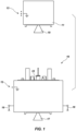
- FIG. 1 is a side elevation view of two spacecraft in proximity in space according to one embodiment.
- first spacecraft 10 may be designed to dock to second spacecraft 11.
- First spacecraft 10 may be a servicer spacecraft designed to provide service to second spacecraft 11.
- second spacecraft 11 may be a satellite in orbit around a body such as the Earth. If second spacecraft 11 is in orbit around Earth, second spacecraft 11 may be in low or medium Earth orbit, geosynchronous or above-geosynchronous orbit, or any other orbit.
- First spacecraft 10 may have a capture apparatus 23 with a probe and a propulsion system.
- the propulsion system of first spacecraft 10 may include one or more main thrusters 17, one or more gimbaled thrusters 18, or both.
- Main thruster 17, gimbaled thrusters 18, or both may be electric propulsion apparatuses.
- Second spacecraft 11 may have an engine 19.
- Engine 19 can be any type of suitable engine or motor for a spacecraft, including a liquid apogee engine or a solid fuel motor.
- First spacecraft 10 may have a first static potential 12, and second spacecraft 11 may have a second static potential 13.
- a differential between first static potential 12 and second static potential 13 may cause an electrostatic discharge. Such an electrostatic discharge may cause damage to first spacecraft 10, second spacecraft 11, or both, unless the differential between first static potential 12 and second static potential 13 is mitigated.
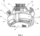
- FIG. 2 is a perspective diagram of a passive electrostatic discharge mitigation system 20 according to one embodiment.
- a circuit 32, as show in FIG. 3 of passive electrostatic discharge mitigation system 20 may be housed within a housing or box 24.
- Passive electrostatic discharge system 20 may be electrically connected to capture apparatus 23 or another portion of first spacecraft 10.
- Passive electrostatic discharge system 20 may also be electrically connected to a first electrical contact apparatus 25.
- First electrical contact apparatus 25 may include one or more compliant members (e.g., whiskers 26). Whiskers 26 comprise an electrically conductive material. Whiskers 26 may be comprised at least in part of beryllium copper.
- FIG. 3 is a diagram of a circuit 32 of a passive electrostatic discharge mitigation system 20 according to one embodiment.
- Passive electrostatic discharge mitigation system 20 may be configured as a resistance inductance, or RL, circuit comprising one or more resistive elements 27 and one or more inductive elements 28.
- the one or more inductive elements 28 may be an inductor, or one or more ferrite beads, one or more chokes, or another inductive element.
- the one or more resistive elements 27 may be one or more resistors and, in some embodiments, may be configured to provide a resistance of more than 1 megaohm and, in some embodiments, may be configured to provide a resistance of greater than or equal to 15 megaohms.
- the passive electrostatic discharge mitigation system 20 provides an equalization path for the voltage differential between the two spacecraft and allows the different static charges to equalize.
- the passive electrostatic discharge mitigation system 20 static voltage differential between the two spacecraft 10, 11 may be converted into heat to remove energy. This dissipation will reduce, or in some instances eliminate, electrostatic discharges and the amplitude and rise time of any associated voltage spikes that may be detrimental to either spacecraft.
- the voltage differential may be discharged over a period of time, for example 50-90 nanoseconds or more.
- discharge current may be reduced below 800 milliamps by passive electrostatic discharge mitigation system 20.
- the one or more inductive elements 28 and one or more resistive elements 27 may be selected to accommodate a transient static potential difference between first spacecraft 10 and second spacecraft 11 of up to or more than 10 kilovolts.
- the passive electrostatic discharge mitigation system 20 may be configured to have parallel circuit paths that may mitigate the risk of individual component failures.
- FIG. 4 is a perspective view of a housing 24 for a passive electrostatic discharge mitigation system 20 ( FIG. 2 ).
- Insulated conductor 21 provides electrical connection between the passive electrostatic discharge mitigation system 20 and at least one first electrical contact apparatus 25 ( FIG. 2 ), wherein first electrical contact apparatus 25 may comprise a compliant member which may be in the form of whisker 26 ( FIG. 2 ).
- Insulated grounding conductor 22 provides electrical connection between the passive electrostatic discharge mitigation system 20 and capture apparatus 23 or elsewhere on a body of first spacecraft 10 ( FIG. 1 ).
- FIG. 5 is a perspective view of a housing 24 for a passive electrostatic discharge mitigation system 20 ( FIG. 2 ) mounted to capture apparatus 23.
- Insulated conductor 21 provides electrical connection between the passive electrostatic discharge mitigation system 20 and at least one first electrical contact apparatus 25, wherein first electrical contact apparatus 25 may comprise a compliant member such as whisker 26.
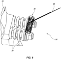
- FIG. 6 is a perspective view of first electrical contact apparatus 25.
- First electrical contact apparatus 25 may include one or more compliant members such as whiskers 26.
- Whiskers 26 may comprise a spring element 29 that may increase compliance of whiskers 26.
- Spring element 29 may be a torsion spring. Spring element 29 may allow whiskers 26 to move in a substantially rotational manner when whiskers 26 contact engine 19 ( FIG. 2 ) or another physical structure on the second spacecraft 11 ( FIG. 1 ).
- First electrical contact apparatus 25 may be designed to be electrically isolated from capture apparatus 23, for example, by one or more insulated posts 30 that electrically isolate the conductive components, such as the whiskers 26, from the capture apparatus 23.
- Insulated posts 30 may be comprised of a machinable glass ceramic or other insulating material sufficient to electrically isolate the conductive components.
- the conductive components of first electrical contact apparatus 25 may be positioned 0.25 inch (0.635 cm) or more from the closest conductive component of capture apparatus 23, or another suitable distance to prevent charge creep or arcing.
- FIG. 7 is a perspective view of a capture apparatus 23 with a passive electrostatic discharge mitigation system 20 mounted thereon approaching the engine 19 of the second spacecraft 11.
- Whiskers 26 may be designed to be of a sufficient length to ensure that at least one whisker 26 provides the first point of physical contact between first spacecraft 10 and second spacecraft 11.
- Whiskers 26 may be designed to be of a sufficient length to ensure that at least one whisker 26 is the only physical structure on the first spacecraft 10 to come within a distance that would allow a static electric arc between first spacecraft 10 and second spacecraft 11 before any portion of first spacecraft 10 physically contacts second spacecraft 11.
- whiskers 26 may be at least 6 inches (15.24 cm) in length.
- FIG. 8 depicts charge potential differentials of a first spacecraft in relation to a second spacecraft for use with an active electrostatic discharge mitigation system, according to one embodiment.
- FIG. 8 graphically represents sample anticipated static potential, or charge, differences between various portions of first spacecraft 10 and second spacecraft 11.
- static potential differences may be on the order of 10 kilovolts or more and capacitance between the vehicles may be on the order of 100 picofarads or more.
- FIGS. 9A and 9B depict an active electrostatic discharge mitigation system 31 using plasma.
- the active electrostatic discharge mitigation system 31 may create a plasma field that can engulf both the first spacecraft 10 and the second spacecraft 11.
- the active electrostatic discharge mitigation system 31 creates the plasma field using one or more electric propulsion engines of first spacecraft 10, which may be main thruster 17, one or more gimbaled thrusters 18, both, or another engine.
- the one or more electric propulsion engines may be Hall Effect Thrusters.
- the plasma field created by the active electrostatic discharge mitigation system 31 may be low temperature plasma. Active electrostatic discharge mitigation system 31 can be operated to reduce the static potential measured to ground reference of each of first spacecraft 10 and second spacecraft 11.
- the reduction of static potential differential between first spacecraft 10 and second spacecraft 11 may be to a level less than about 5 kilovolts, less than about 1 kilovolt, less than about 200 volts, or less than about 100 volts in various embodiments.
- use of the active electrostatic discharge mitigation system 31 may reduce potential ground bounce between the first spacecraft 10 and second spacecraft 11.
- the first spacecraft 10 may have both a passive electrostatic discharge mitigation system 20 and an active electrostatic discharge mitigation system 31.
- active electrostatic discharge mitigation system 31 may reduce differential static potential between first spacecraft 10 and second spacecraft 11 before contact, and passive electrostatic discharge mitigation system 20 to mitigate remaining differential static potential between first spacecraft 10 and second spacecraft 11 upon contact or approach sufficient to permit electrostatic arcing.
- passive electrostatic discharge mitigation system 20 and active electrostatic discharge mitigation system 31 provide redundancy upon component failure of either system.
- Embodiment 1 A system for mitigating electrostatic discharge between a first space vehicle and a second space vehicle comprising a passive electrostatic discharge mitigation system situated on the first space vehicle, wherein the passive electrostatic discharge mitigation system comprises one or more resistors.
- Embodiment 2 The system of Embodiment 1, wherein the passive electrostatic discharge mitigation system reduces an electrostatic discharge current between the first space vehicle and the second space vehicle to less than or equal to about 800 milliamps over a time period of less than or equal to about 90 nanoseconds.
- Embodiment 3 The system of Embodiment 1, wherein the passive electrostatic discharge mitigation system further comprises one or more inductive elements selected from the group comprising inductors, ferrite beads, and chokes.
- Embodiment 4 The system of Embodiment 1, wherein the system further includes one or more whiskers.
- Embodiment 5 A system for mitigating electrostatic discharge between a first space vehicle and a second space vehicle comprising an active electrostatic discharge system situated on the first space vehicle, wherein the active electrostatic discharge system manipulates a plasma field.
- Embodiment 6 The system of Embodiment 5, wherein the plasma field is the plasma field of the first space vehicle.
- Embodiment 7 The system of Embodiment 5, wherein the plasma field is the plasma field of the second space vehicle.
- Embodiment 8 The system of Embodiment 5, wherein the active electrostatic discharge system manipulates the plasma field using an electric propulsion apparatus.
- Embodiment 9 The system of Embodiment 8, wherein the electric propulsion apparatus produces a plasma field significant enough to reduce the potential between the first space vehicle and the second space vehicle to less than about +/- 200 volts.
- Embodiment 10 The system of Embodiment 8, wherein the electric propulsion apparatus is one or more Hall Effect Thrusters.
- Embodiment 11 A system for mitigating electrostatic discharge between a first space vehicle and a second space vehicle, comprising: a propulsion mechanism for maneuvering the first space vehicle in space; a capture mechanism positioned on the first space vehicle for at least temporarily joining the first space vehicle to the second space vehicle; and a mechanism for passively mitigating electrostatic discharge when the first space vehicle and the second space vehicle are joining.
- Embodiment 12 The system of Embodiment 11, wherein the mechanism for passively mitigating electrostatic discharge includes one or more whiskers.
- Embodiment 13 The system of Embodiment 12, wherein the whisker provides the first physical contact between the first space vehicle and the second space vehicle.
- Embodiment 14 The system of Embodiment 13, wherein the whisker is configured to contact an engine of the second space vehicle when the first space vehicle and the second space vehicle are joining.
- Embodiment 15 The system of Embodiment 14, wherein the whisker is positioned to contact the engine before any other physical structure on the second space vehicle when the first space vehicle and the second space vehicle are joining.
- Embodiment 16 The system of Embodiment 15, wherein the engine is a liquid apogee engine.
- Embodiment 17 The system of Embodiment 12, wherein the capture mechanism includes a probe.
- Embodiment 18 The system of Embodiment 17, wherein the whisker is positioned on the probe.
- Embodiment 19 The system of Embodiment 13, wherein there are a plurality of whiskers.
- Embodiment 20 The system of Embodiment 13, wherein the whisker extends from the first space vehicle in a direction toward a location where the second space vehicle is positioned when the first space vehicle and the second space vehicle are joining.
- Embodiment 21 The system of Embodiment 13, wherein the whisker is configured to be highly compliant.
- Embodiment 22 The system of Embodiment 21, wherein the compliance is provided in part by a torsion spring.
- Embodiment 23 The system of Embodiment 13, wherein the whisker is comprised of beryllium copper.
- Embodiment 24 A method for mitigating electrostatic discharge between a first space vehicle and a second space vehicle comprising: providing a passive electrostatic discharge mitigation system on the first space vehicle, wherein the passive electrostatic discharge mitigation system comprises one or more resistors; and configuring the first contact between the first space vehicle and the second space vehicle to ensure that any electrostatic discharge between the first space vehicle and the second space vehicle is directed through the passive electrostatic discharge mitigation system.
- Embodiment 25 The method of Embodiment 24, wherein the method further comprises reducing an electrostatic discharge current between the first space vehicle and the second space vehicle to less than or equal to about 800 milliamps over a time period of less than or equal to about 90 nanoseconds using the passive electrostatic discharge mitigation system.
- Embodiment 26 The method of Embodiment 24, wherein the passive electrostatic discharge mitigation system further comprises one or more inductive elements selected from the group comprising inductors, ferrite beads, and chokes.
- Embodiment 27 The method of Embodiment 24, wherein the passive electrostatic discharge mitigation system further includes one or more whiskers.
- Embodiment 28 A method for mitigating electrostatic discharge between a first space vehicle and a second space vehicle comprising: providing an active electrostatic discharge system situated on the first space vehicle; and manipulating a plasma field using the active electrostatic discharge system.
- Embodiment 29 The method of Embodiment 28, wherein the manipulating of the plasma field comprises manipulating the plasma field of the first space vehicle.
- Embodiment 30 The method of Embodiment 28, wherein the manipulating of the plasma field comprises manipulating the plasma field of the second space vehicle.
- Embodiment 31 The method of Embodiment 28, wherein the manipulating of the plasma field comprises manipulating the plasma field using an electric propulsion apparatus.
- Embodiment 32 The method of Embodiment 31, wherein the method further comprises producing a plasma field significant enough to reduce the potential between the first space vehicle and the second space vehicle to less than about +/- 200 volts using the electric propulsion apparatus.
- Embodiment 33 The method of Embodiment 31, wherein the electric propulsion apparatus is one or more Hall Effect Thrusters.
- Embodiment 34 A method for mitigating electrostatic discharge between a first space vehicle and a second space vehicle, comprising: providing a capture mechanism positioned on the first space vehicle for at least temporarily joining the first space vehicle to the second space vehicle; maneuvering the first space vehicle in space in proximity to the second space vehicle; and providing a mechanism for passively mitigating electrostatic discharge between the first space vehicle and the second space vehicle.
- Embodiment 35 The method of Embodiment 34, wherein the mechanism for passively mitigating electrostatic discharge includes a whisker.
- Embodiment 36 The method of Embodiment 35, wherein the method further includes physically contacting the first space vehicle and the second space vehicle, wherein the whisker provides the first physical contact between the first space vehicle and the second space vehicle when the first space vehicle and the second space vehicle are joining.
- Embodiment 37 The method of Embodiment 36, wherein the whisker is configured to contact an engine of the second space vehicle when the first space vehicle and the second space vehicle are joining.
- Embodiment 38 The method of Embodiment 37, wherein the whisker is configured to contact the engine before any other physical structure on the second space vehicle when the first space vehicle and the second space vehicle are joining.
- Embodiment 39 The method of Embodiment 38, wherein the engine is a liquid apogee engine.
- Embodiment 40 The method of Embodiment 35, wherein the capture mechanism includes a probe.
- Embodiment 41 The method of Embodiment 40, wherein the whisker is positioned on the probe.
- Embodiment 42 The method of Embodiment 36, wherein there are a plurality of whiskers.
- Embodiment 43 The method of Embodiment 36, wherein the whisker extends from the first space vehicle in a direction toward a location where the second space vehicle is positioned when the first space vehicle and the second space vehicle are joining.
- Embodiment 44 The method of Embodiment 36, wherein the whisker is highly compliant.
- Embodiment 45 The method of Embodiment 44, wherein the compliance is provided in part by a torsion spring.
- Embodiment 46 The method of Embodiment 36, wherein the whisker is comprised of beryllium copper.
- Embodiment 47 A system for mitigating electrostatic discharge between a first space vehicle and a second space vehicle comprising: a passive electrostatic discharge mitigation system situated on the first space vehicle, wherein the passive electrostatic discharge mitigation system comprises one or more resistors; and an active electrostatic discharge system situated on the first space vehicle, wherein the active electrostatic discharge system manipulates a plasma field.
- Embodiment 48 The system of Embodiment 47, wherein the passive electrostatic discharge mitigation system reduces an electrostatic discharge current between the first space vehicle and the second space vehicle to less than or equal to about 800 milliamps over a time period of less than or equal to about 90 nanoseconds.
- Embodiment 49 The system of Embodiment 47, wherein the passive electrostatic discharge mitigation system further comprises one or more inductive elements selected from the group comprising inductors, ferrite beads, and chokes.
- Embodiment 50 The system of Embodiment 47, wherein the system further includes one or more whiskers.
- Embodiment 51 The system of Embodiment 47, wherein the plasma field is the plasma field of the first space vehicle.
- Embodiment 52 The system of Embodiment 47, wherein the plasma field is the plasma field of the second space vehicle.
- Embodiment 53 The system of Embodiment 47, wherein the active electrostatic discharge system manipulates the plasma field using an electric propulsion apparatus.
- Embodiment 54 The system of Embodiment 53, wherein the electric propulsion apparatus produces a plasma field significant enough to reduce the potential between the first space vehicle and the second space vehicle to less than about +/- 200 volts.
- Embodiment 55 The system of Embodiment 53, wherein the electric propulsion apparatus is one or more Hall Effect Thrusters.
- Embodiment 56 The system of Embodiment 49, wherein the whisker a configured to provide the first physical contact between the first space vehicle and the second space vehicle.
- Embodiment 57 The system of Embodiment 56, wherein the whisker is configured to contact an engine of the second space vehicle.
- Embodiment 58 The system of Embodiment 57, wherein the whisker is configured to contact the engine before any other physical structure on the second space vehicle.
- Embodiment 59 The system of Embodiment 49, wherein a capture mechanism includes a probe.
- Embodiment 60 The system of Embodiment 59, wherein the whisker is positioned on the probe.
- Embodiment 61 The system of Embodiment 60, wherein there are a plurality of whiskers.
- Embodiment 62 The system of Embodiment 60, wherein the whisker extends from the first space vehicle in a direction toward a location where the second space vehicle is positioned when the first space vehicle and the second space vehicle are joining.
- Embodiment 63 The system of Embodiment 60, wherein the whisker is highly compliant.
- Embodiment 64 The system of Embodiment 63, wherein the compliance is provided in part by a torsion spring.
- Embodiment 65 The system of Embodiment 60, wherein the whisker is comprised of beryllium copper.
- Embodiment 66 A method for mitigating electrostatic discharge between a first space vehicle and a second space vehicle comprising: providing an active electrostatic discharge system situated on the first space vehicle; manipulating a plasma field using the active electrostatic discharge system; providing a passive electrostatic discharge mitigation system on the first space vehicle, wherein the passive electrostatic discharge mitigation system comprises one or more resistors; and configuring the first contact between the first space vehicle and the second space vehicle to ensure that any electrostatic discharge between the first space vehicle and the second space vehicle is directed through the passive electrostatic discharge mitigation system.
- Embodiment 67 The method of Embodiment 66, wherein the method further comprises reducing an electrostatic discharge current between the first space vehicle and the second space vehicle to less than or equal to about 800 milliamps over a time period of less than or equal to about 90 nanoseconds using the passive electrostatic discharge mitigation system.
- Embodiment 68 The method of Embodiment 66, wherein the passive electrostatic discharge mitigation system further comprises one or more inductive elements selected from the group comprising inductors, ferrite beads, and chokes.
- Embodiment 69 The method of Embodiment 66, wherein the passive electrostatic discharge mitigation system further includes one or more whiskers.
- Embodiment 70 The method of Embodiment 66, wherein the manipulating of the plasma field comprises manipulating the plasma field of the first space vehicle.
- Embodiment 71 The method of Embodiment 66, wherein the manipulating of the plasma field comprises manipulating the plasma field of the second space vehicle.
- Embodiment 72 The method of Embodiment 66, wherein the manipulating of the plasma field comprises manipulating the plasma field using an electric propulsion apparatus.
- Embodiment 73 The method of Embodiment 72, wherein the method further comprises producing a plasma field significant enough to reduce the potential between the first space vehicle and the second space vehicle to less than about +/- 200 volts using the electric propulsion apparatus.
- Embodiment 74 The method of Embodiment 72, wherein the electric propulsion apparatus is one or more Hall Effect Thrusters.
- Embodiment 75 The method of Embodiment 69, wherein the method further includes physically contacting the first space vehicle and the second space vehicle, wherein the whisker provides the first physical contact between the first space vehicle and the second space vehicle when the first space vehicle and the second space vehicle are joining.
- Embodiment 76 The method of Embodiment 75, wherein the whisker is configured to contact an engine of the second space vehicle.
- Embodiment 77 The method of Embodiment 76, wherein the whisker is configured to contact the engine before any other physical structure on the second space vehicle.
- Embodiment 78 The method of Embodiment 76, wherein the engine is a liquid apogee engine.
- Embodiment 79 The method of Embodiment 68, wherein a capture mechanism includes a probe.
- Embodiment 80 The method of Embodiment 79, wherein the whisker is positioned on the probe.
- Embodiment 81 The method of Embodiment 80, wherein the whisker extends from the first space vehicle in a direction toward a location where the second space vehicle is positioned when the first space vehicle and the second space vehicle are joining.
- Embodiment 82 The method of Embodiment 69, wherein the whisker is highly compliant.
- Embodiment 83 The method of Embodiment 82, wherein the compliance is provided in part by a torsion spring.
- Embodiment 84 The method of Embodiment 68, wherein the whisker is comprised of beryllium copper.
Landscapes
- Engineering & Computer Science (AREA)
- Remote Sensing (AREA)
- Aviation & Aerospace Engineering (AREA)
- Chemical & Material Sciences (AREA)
- Combustion & Propulsion (AREA)
- Critical Care (AREA)
- Plasma & Fusion (AREA)
- Health & Medical Sciences (AREA)
- Physics & Mathematics (AREA)
- Emergency Medicine (AREA)
- General Health & Medical Sciences (AREA)
- Plasma Technology (AREA)
- Elimination Of Static Electricity (AREA)
- Protection Of Static Devices (AREA)
- Catching Or Destruction (AREA)
- Aiming, Guidance, Guns With A Light Source, Armor, Camouflage, And Targets (AREA)
Abstract
Description
- This application claims the benefit of the filing date of
United States Provisional Patent Application Serial Number 62/484,969, filed April 13, 2017 United States Patent Application Serial No. 15/829,758, filed December 1, 2017 - The present disclosure relates systems and methods for addressing the challenges that arise with regard to electrostatic discharge when a first spacecraft is operating in proximity with a second spacecraft, and particularly when the first spacecraft approaches the second spacecraft to dock or otherwise contact the second spacecraft.
- Thousands of spacecraft orbit the Earth for performing various functions including, for example, telecommunication, GPS navigation, weather forecasting, and mapping. More complex large spacecraft are also in orbit, including the International Space Station, to which nations throughout the world send crew and supplies for scientific investigation and research. However, spacecraft periodically require servicing to extend their functioning life span. Servicing may include, for example, component repair, refueling, orbit raising, stationkeeping, momentum balancing, or other maintenance. Without life extension maintenance, these spacecraft may fall out of service, and replacement is generally extraordinarily expensive and can have a lead time of years. In the case of unmanned spacecraft, to accomplish such servicing, a servicing spacecraft may be sent into orbit to dock with a client spacecraft requiring maintenance, and subsequent to docking, perform life-extending maintenance on the client.
- However, spacecraft or other bodies in orbit often possess different electrical potentials. When two spacecraft approach each other, a significant risk arises that an electrostatic discharge could occur between the two spacecraft. Spacecraft contain numerous electronic systems that could be damaged or destroyed by such an electrostatic discharge event. Various patents and publications have considered how to mitigate the risk of an electrostatic discharge event, including
U.S. Patent Nos. 7,070,151 ,7,216,833 ,7,216,834 ,7,461,818 ,7,484,690 ,7,575,199 ,7,588,213 ,7,611,096 ,7,611,097 ,7,624,950 , and8,205,838 , the disclosure of each of which is hereby incorporated herein in its entirety by this reference. However, an improved system and method for mitigating electrostatic discharge between a first spacecraft and a second spacecraft is desirable. - Methods and systems for mitigating the risk of an electrostatic discharge due to static charge differentials between a first spacecraft and a second spacecraft are disclosed herein. Various embodiments teach a passive electrostatic discharge mitigation device facilitating the safe reduction of static potential between the first and second spacecraft prior to and/or upon contact. Some embodiments provide an apparatus to direct the flow of a static discharge current in a manner that minimizes risk to the electronic components of the first and second spacecraft, which may be accomplished by providing one or more whiskers electrically connected to a passive electrostatic discharge mitigation device. Some embodiments provide for actively mitigating static potential between a first spacecraft and a second spacecraft by means of an electric propulsion system provided on the first spacecraft. Some embodiments provide for both actively and passively mitigating static potential between the first spacecraft and the second spacecraft.
- Certain embodiments teach a system and method for mitigating electrostatic discharge between a first space vehicle and a second space vehicle comprising a passive electrostatic discharge mitigation system situated on the first space vehicle, wherein the passive electrostatic discharge mitigation system comprises one or more resistors and wherein the passive electrostatic discharge mitigation system comprises one or more ferrite beads. In some embodiments, the passive electrostatic discharge mitigation system reduces an electrostatic discharge current between the first space vehicle and the second space vehicle to less than or equal to about 800 milliamps over a time period of less than or equal to about 90 nanoseconds. Some embodiments further comprise one or more whiskers as part of the passive electrostatic discharge mitigation system.
- Certain embodiments teach a system and method for mitigating electrostatic discharge between a first space vehicle and a second space vehicle comprising an active electrostatic discharge system situated on the first space vehicle, wherein the active electrostatic discharge system manipulates a plasma field. In various embodiments, the manipulated plasma field is the plasma field of the first space vehicle, the plasma field of the second space vehicle, or the plasma fields of both the first and second space vehicles. The active electrostatic discharge system may manipulate the plasma field using an electric propulsion apparatus. Some embodiments provide that the electric propulsion apparatus produce a plasma field significant enough to reduce the potential between the first space vehicle and the second space vehicle to less than about +/- 200 volts. The electric propulsion apparatus may be one or more Hall Effect Thrusters.
- Certain embodiments teach a system and method for mitigating electrostatic discharge between a first space vehicle and a second space vehicle, comprising a propulsion mechanism for maneuvering the first space vehicle in space; a capture mechanism positioned on the first space vehicle for at least temporarily joining the first space vehicle to the second space vehicle; and a mechanism for passively mitigating electrostatic discharge. The mechanism for passively mitigating electrostatic discharge may include one or more compliant members, which in some embodiments may be one or more whiskers. In some embodiments, the compliant member provides the first physical contact between the first space vehicle and the second space vehicle. The compliant member may contact an engine of the second space vehicle and, in some embodiments, the compliant member always contacts the engine before any other physical structure on the second space vehicle. The engine of the second space vehicle may be a liquid apogee engine. According to some embodiments, the capture mechanism includes a probe. The compliant member may be positioned on the probe. Some embodiments provide that the compliant member extends from the first space vehicle in a direction toward the second space vehicle. The compliant member may be highly compliant. In some embodiments, the compliance of the compliant member is provided in part by a torsion spring. According to some embodiments, the compliant member is comprised of beryllium copper.
- Certain embodiments teach a system and method for mitigating electrostatic discharge between a first space vehicle and a second space vehicle comprising a passive electrostatic discharge mitigation system situated on the first space vehicle; and an active electrostatic discharge system situated on the first space vehicle. In some embodiments, the passive electrostatic discharge mitigation system comprises one or more resistors and wherein the passive electrostatic discharge mitigation system comprises one or more ferrite beads. In some embodiments, the active electrostatic discharge system manipulates a plasma field. The passive electrostatic discharge mitigation system may reduce an electrostatic discharge current between the first space vehicle and the second space vehicle to less than or equal to about 800 milliamps over a time period of less than or equal to about 90 nanoseconds. The system further may include a whisker or a plurality of whiskers. The whisker may provide the first physical contact between the first space vehicle and the second space vehicle, and may contact an engine of the second space vehicle. The whisker may extend from the first space vehicle in a direction toward the second space vehicle. In some embodiments, the whisker always contacts the engine before any other physical structure on the second space vehicle. The capture mechanism may include a probe, and the whisker may be positioned on the probe in some embodiments. The whisker may be highly compliant and, in some embodiments, the compliance is provided in part by a torsion spring. In some embodiments, the whisker is comprised of beryllium copper. In some embodiments, the manipulated plasma field is the plasma field of the first space vehicle, the plasma field of the second space vehicle, or the plasma fields of both the first and second space vehicles. The active electrostatic discharge system may manipulate the plasma field using an electric propulsion apparatus, which may be one or more Hall Effect Thrusters in some embodiments. The electric propulsion apparatus may produce a plasma field significant enough to reduce the potential between the first space vehicle and the second space vehicle to less than about +/- 200 volts.
- The above summary is not intended to describe each illustrated embodiment or every implementation of the present disclosure.
- The drawings included in the present application are incorporated into, and form part of, the specification. They illustrate embodiments of the present disclosure and, along with the description, serve to explain the principles of the disclosure. The drawings are only illustrative of certain embodiments and do not limit the disclosure.
-
FIG. 1 is a side elevational view of a first spacecraft and a second spacecraft in proximity, according to one or more embodiments. -
FIG. 2 is a perspective diagram of a passive electrostatic discharge mitigation system, according to one or more embodiments. -
FIG. 3 is a diagram of a circuit of a passive electrostatic discharge mitigation system, according to one or more embodiments. -
FIG. 4 is a perspective view of a housing for a passive electrostatic discharge mitigation system, according to one or more embodiments. -
FIG. 5 is a perspective view of a housing for a passive electrostatic discharge mitigation system mounted on a capture apparatus, according to one or more embodiments. -
FIG. 6 is a perspective view of a first electrical contact apparatus, according to one or more embodiments. -
FIG. 7 is a perspective view of a capture apparatus with a passive electrostatic discharge mitigation system mounted thereon approaching an engine of a second spacecraft, according to one or more embodiments. -
FIG. 8 is a graphical representation of a sample anticipated static potential difference between portions of a first spacecraft and a second spacecraft, according to one or more embodiments. -
FIGS. 9A and9B are graphical representations of the operation of an active electrostatic discharge mitigation system to create plasma, according to one or more embodiments. - Although embodiments of the disclosure disclosed herein are amenable to various modifications and alternative forms, specifics thereof have been shown by way of example in the drawings and will be described in detail. It should be understood, however, that the intention is not to limit the disclosure to the particular embodiments described. On the contrary, the intention is to cover all modifications, equivalents, and alternatives falling within the scope of the disclosure.
- As used herein, the term "substantially" in reference to a given parameter means and includes to a degree that one skilled in the art would understand that the given parameter, property, or condition is met with a small degree of variance, such as within acceptable manufacturing tolerances. For example, a parameter that is substantially met may be at least about 90% met, at least about 95% met, or even at least about 99% met.
- The inventors have recognized the risk of damage from electrostatic discharges due to static charge differentials associated with an approach of a first spacecraft to a second spacecraft. In some embodiments, the first spacecraft may comprise a capture assembly that beneficially provides electrostatic mitigation to protect electronic components in the first spacecraft, the second spacecraft, or both. Some embodiments provide systems and methods for reducing the static potential between a first and second spacecraft in a manner that protects the components of both spacecraft.
-
FIG. 1 is a side elevation view of two spacecraft in proximity in space according to one embodiment. In some embodiments,first spacecraft 10 may be designed to dock tosecond spacecraft 11.First spacecraft 10 may be a servicer spacecraft designed to provide service tosecond spacecraft 11. According to some embodiments,second spacecraft 11 may be a satellite in orbit around a body such as the Earth. Ifsecond spacecraft 11 is in orbit around Earth,second spacecraft 11 may be in low or medium Earth orbit, geosynchronous or above-geosynchronous orbit, or any other orbit. -
First spacecraft 10 may have acapture apparatus 23 with a probe and a propulsion system. The propulsion system offirst spacecraft 10 may include one or moremain thrusters 17, one or moregimbaled thrusters 18, or both.Main thruster 17,gimbaled thrusters 18, or both may be electric propulsion apparatuses.Second spacecraft 11 may have anengine 19.Engine 19 can be any type of suitable engine or motor for a spacecraft, including a liquid apogee engine or a solid fuel motor.First spacecraft 10 may have a firststatic potential 12, andsecond spacecraft 11 may have a secondstatic potential 13. Upon approach or contact offirst spacecraft 10 tosecond spacecraft 11, a differential between firststatic potential 12 and second static potential 13 may cause an electrostatic discharge. Such an electrostatic discharge may cause damage tofirst spacecraft 10,second spacecraft 11, or both, unless the differential between firststatic potential 12 and secondstatic potential 13 is mitigated. -
FIG. 2 is a perspective diagram of a passive electrostaticdischarge mitigation system 20 according to one embodiment. Acircuit 32, as show inFIG. 3 , of passive electrostaticdischarge mitigation system 20 may be housed within a housing orbox 24. Passiveelectrostatic discharge system 20 may be electrically connected to captureapparatus 23 or another portion offirst spacecraft 10. Passiveelectrostatic discharge system 20 may also be electrically connected to a firstelectrical contact apparatus 25. Firstelectrical contact apparatus 25 may include one or more compliant members (e.g., whiskers 26).Whiskers 26 comprise an electrically conductive material.Whiskers 26 may be comprised at least in part of beryllium copper. -
FIG. 3 is a diagram of acircuit 32 of a passive electrostaticdischarge mitigation system 20 according to one embodiment. Passive electrostaticdischarge mitigation system 20 may be configured as a resistance inductance, or RL, circuit comprising one or moreresistive elements 27 and one or moreinductive elements 28. In some embodiments, the one or moreinductive elements 28 may be an inductor, or one or more ferrite beads, one or more chokes, or another inductive element. The one or moreresistive elements 27 may be one or more resistors and, in some embodiments, may be configured to provide a resistance of more than 1 megaohm and, in some embodiments, may be configured to provide a resistance of greater than or equal to 15 megaohms. Whenfirst spacecraft 10 andsecond spacecraft 11 make contact or come in close enough proximity for a static electric arc to occur between thefirst spacecraft 10 andsecond spacecraft 11, the passive electrostaticdischarge mitigation system 20 provides an equalization path for the voltage differential between the two spacecraft and allows the different static charges to equalize. - As a result of the passive electrostatic
discharge mitigation system 20, static voltage differential between the twospacecraft discharge mitigation system 20. According to certain embodiments, the one or moreinductive elements 28 and one or moreresistive elements 27 may be selected to accommodate a transient static potential difference betweenfirst spacecraft 10 andsecond spacecraft 11 of up to or more than 10 kilovolts. In some embodiments, the passive electrostaticdischarge mitigation system 20 may be configured to have parallel circuit paths that may mitigate the risk of individual component failures. -
FIG. 4 is a perspective view of ahousing 24 for a passive electrostatic discharge mitigation system 20 (FIG. 2 ).Insulated conductor 21 provides electrical connection between the passive electrostaticdischarge mitigation system 20 and at least one first electrical contact apparatus 25 (FIG. 2 ), wherein firstelectrical contact apparatus 25 may comprise a compliant member which may be in the form of whisker 26 (FIG. 2 ).Insulated grounding conductor 22 provides electrical connection between the passive electrostaticdischarge mitigation system 20 andcapture apparatus 23 or elsewhere on a body of first spacecraft 10 (FIG. 1 ). -
FIG. 5 is a perspective view of ahousing 24 for a passive electrostatic discharge mitigation system 20 (FIG. 2 ) mounted to captureapparatus 23.Insulated conductor 21 provides electrical connection between the passive electrostaticdischarge mitigation system 20 and at least one firstelectrical contact apparatus 25, wherein firstelectrical contact apparatus 25 may comprise a compliant member such aswhisker 26. -
FIG. 6 is a perspective view of firstelectrical contact apparatus 25. Firstelectrical contact apparatus 25 may include one or more compliant members such aswhiskers 26.Whiskers 26 may comprise aspring element 29 that may increase compliance ofwhiskers 26.Spring element 29 may be a torsion spring.Spring element 29 may allowwhiskers 26 to move in a substantially rotational manner whenwhiskers 26 contact engine 19 (FIG. 2 ) or another physical structure on the second spacecraft 11 (FIG. 1 ). Firstelectrical contact apparatus 25 may be designed to be electrically isolated fromcapture apparatus 23, for example, by one or moreinsulated posts 30 that electrically isolate the conductive components, such as thewhiskers 26, from thecapture apparatus 23.Insulated posts 30 may be comprised of a machinable glass ceramic or other insulating material sufficient to electrically isolate the conductive components. In some embodiments, the conductive components of firstelectrical contact apparatus 25 may be positioned 0.25 inch (0.635 cm) or more from the closest conductive component ofcapture apparatus 23, or another suitable distance to prevent charge creep or arcing. -
FIG. 7 is a perspective view of acapture apparatus 23 with a passive electrostaticdischarge mitigation system 20 mounted thereon approaching theengine 19 of thesecond spacecraft 11.Whiskers 26 may be designed to be of a sufficient length to ensure that at least onewhisker 26 provides the first point of physical contact betweenfirst spacecraft 10 andsecond spacecraft 11.Whiskers 26 may be designed to be of a sufficient length to ensure that at least onewhisker 26 is the only physical structure on thefirst spacecraft 10 to come within a distance that would allow a static electric arc betweenfirst spacecraft 10 andsecond spacecraft 11 before any portion offirst spacecraft 10 physically contactssecond spacecraft 11. In some embodiments,whiskers 26 may be at least 6 inches (15.24 cm) in length. -
FIG. 8 depicts charge potential differentials of a first spacecraft in relation to a second spacecraft for use with an active electrostatic discharge mitigation system, according to one embodiment.FIG. 8 graphically represents sample anticipated static potential, or charge, differences between various portions offirst spacecraft 10 andsecond spacecraft 11. In some embodiments, static potential differences may be on the order of 10 kilovolts or more and capacitance between the vehicles may be on the order of 100 picofarads or more. -
FIGS. 9A and9B depict an active electrostaticdischarge mitigation system 31 using plasma. In some embodiments, the active electrostaticdischarge mitigation system 31 may create a plasma field that can engulf both thefirst spacecraft 10 and thesecond spacecraft 11. In some embodiments, the active electrostaticdischarge mitigation system 31 creates the plasma field using one or more electric propulsion engines offirst spacecraft 10, which may bemain thruster 17, one or moregimbaled thrusters 18, both, or another engine. The one or more electric propulsion engines may be Hall Effect Thrusters. The plasma field created by the active electrostaticdischarge mitigation system 31 may be low temperature plasma. Active electrostaticdischarge mitigation system 31 can be operated to reduce the static potential measured to ground reference of each offirst spacecraft 10 andsecond spacecraft 11. The reduction of static potential differential betweenfirst spacecraft 10 andsecond spacecraft 11 may be to a level less than about 5 kilovolts, less than about 1 kilovolt, less than about 200 volts, or less than about 100 volts in various embodiments. In addition, use of the active electrostaticdischarge mitigation system 31 may reduce potential ground bounce between thefirst spacecraft 10 andsecond spacecraft 11. - In some embodiments, the
first spacecraft 10 may have both a passive electrostaticdischarge mitigation system 20 and an active electrostaticdischarge mitigation system 31. In such embodiments, active electrostaticdischarge mitigation system 31 may reduce differential static potential betweenfirst spacecraft 10 andsecond spacecraft 11 before contact, and passive electrostaticdischarge mitigation system 20 to mitigate remaining differential static potential betweenfirst spacecraft 10 andsecond spacecraft 11 upon contact or approach sufficient to permit electrostatic arcing. In such embodiments, passive electrostaticdischarge mitigation system 20 and active electrostaticdischarge mitigation system 31 provide redundancy upon component failure of either system. - Further example embodiments are disclosed below.
- Embodiment 1: A system for mitigating electrostatic discharge between a first space vehicle and a second space vehicle comprising a passive electrostatic discharge mitigation system situated on the first space vehicle, wherein the passive electrostatic discharge mitigation system comprises one or more resistors.
- Embodiment 2: The system of Embodiment 1, wherein the passive electrostatic discharge mitigation system reduces an electrostatic discharge current between the first space vehicle and the second space vehicle to less than or equal to about 800 milliamps over a time period of less than or equal to about 90 nanoseconds.
- Embodiment 3: The system of Embodiment 1, wherein the passive electrostatic discharge mitigation system further comprises one or more inductive elements selected from the group comprising inductors, ferrite beads, and chokes.
- Embodiment 4: The system of Embodiment 1, wherein the system further includes one or more whiskers.
- Embodiment 5: A system for mitigating electrostatic discharge between a first space vehicle and a second space vehicle comprising an active electrostatic discharge system situated on the first space vehicle, wherein the active electrostatic discharge system manipulates a plasma field.
- Embodiment 6: The system of Embodiment 5, wherein the plasma field is the plasma field of the first space vehicle.
- Embodiment 7: The system of Embodiment 5, wherein the plasma field is the plasma field of the second space vehicle.
- Embodiment 8: The system of Embodiment 5, wherein the active electrostatic discharge system manipulates the plasma field using an electric propulsion apparatus.
- Embodiment 9: The system of Embodiment 8, wherein the electric propulsion apparatus produces a plasma field significant enough to reduce the potential between the first space vehicle and the second space vehicle to less than about +/- 200 volts.
- Embodiment 10: The system of Embodiment 8, wherein the electric propulsion apparatus is one or more Hall Effect Thrusters.
- Embodiment 11: A system for mitigating electrostatic discharge between a first space vehicle and a second space vehicle, comprising: a propulsion mechanism for maneuvering the first space vehicle in space; a capture mechanism positioned on the first space vehicle for at least temporarily joining the first space vehicle to the second space vehicle; and a mechanism for passively mitigating electrostatic discharge when the first space vehicle and the second space vehicle are joining.
- Embodiment 12: The system of
Embodiment 11, wherein the mechanism for passively mitigating electrostatic discharge includes one or more whiskers. - Embodiment 13: The system of
Embodiment 12, wherein the whisker provides the first physical contact between the first space vehicle and the second space vehicle. - Embodiment 14: The system of
Embodiment 13, wherein the whisker is configured to contact an engine of the second space vehicle when the first space vehicle and the second space vehicle are joining. - Embodiment 15: The system of Embodiment 14, wherein the whisker is positioned to contact the engine before any other physical structure on the second space vehicle when the first space vehicle and the second space vehicle are joining.
- Embodiment 16: The system of
Embodiment 15, wherein the engine is a liquid apogee engine. - Embodiment 17: The system of
Embodiment 12, wherein the capture mechanism includes a probe. - Embodiment 18: The system of
Embodiment 17, wherein the whisker is positioned on the probe. - Embodiment 19: The system of
Embodiment 13, wherein there are a plurality of whiskers. - Embodiment 20: The system of
Embodiment 13, wherein the whisker extends from the first space vehicle in a direction toward a location where the second space vehicle is positioned when the first space vehicle and the second space vehicle are joining. - Embodiment 21: The system of
Embodiment 13, wherein the whisker is configured to be highly compliant. - Embodiment 22: The system of
Embodiment 21, wherein the compliance is provided in part by a torsion spring. - Embodiment 23: The system of
Embodiment 13, wherein the whisker is comprised of beryllium copper. - Embodiment 24: A method for mitigating electrostatic discharge between a first space vehicle and a second space vehicle comprising: providing a passive electrostatic discharge mitigation system on the first space vehicle, wherein the passive electrostatic discharge mitigation system comprises one or more resistors; and configuring the first contact between the first space vehicle and the second space vehicle to ensure that any electrostatic discharge between the first space vehicle and the second space vehicle is directed through the passive electrostatic discharge mitigation system.
- Embodiment 25: The method of
Embodiment 24, wherein the method further comprises reducing an electrostatic discharge current between the first space vehicle and the second space vehicle to less than or equal to about 800 milliamps over a time period of less than or equal to about 90 nanoseconds using the passive electrostatic discharge mitigation system. - Embodiment 26: The method of
Embodiment 24, wherein the passive electrostatic discharge mitigation system further comprises one or more inductive elements selected from the group comprising inductors, ferrite beads, and chokes. - Embodiment 27: The method of
Embodiment 24, wherein the passive electrostatic discharge mitigation system further includes one or more whiskers. - Embodiment 28: A method for mitigating electrostatic discharge between a first space vehicle and a second space vehicle comprising: providing an active electrostatic discharge system situated on the first space vehicle; and manipulating a plasma field using the active electrostatic discharge system.
- Embodiment 29: The method of
Embodiment 28, wherein the manipulating of the plasma field comprises manipulating the plasma field of the first space vehicle. - Embodiment 30: The method of
Embodiment 28, wherein the manipulating of the plasma field comprises manipulating the plasma field of the second space vehicle. - Embodiment 31: The method of
Embodiment 28, wherein the manipulating of the plasma field comprises manipulating the plasma field using an electric propulsion apparatus. - Embodiment 32: The method of
Embodiment 31, wherein the method further comprises producing a plasma field significant enough to reduce the potential between the first space vehicle and the second space vehicle to less than about +/- 200 volts using the electric propulsion apparatus. - Embodiment 33: The method of
Embodiment 31, wherein the electric propulsion apparatus is one or more Hall Effect Thrusters. - Embodiment 34: A method for mitigating electrostatic discharge between a first space vehicle and a second space vehicle, comprising: providing a capture mechanism positioned on the first space vehicle for at least temporarily joining the first space vehicle to the second space vehicle; maneuvering the first space vehicle in space in proximity to the second space vehicle; and providing a mechanism for passively mitigating electrostatic discharge between the first space vehicle and the second space vehicle.
- Embodiment 35: The method of Embodiment 34, wherein the mechanism for passively mitigating electrostatic discharge includes a whisker.
- Embodiment 36: The method of Embodiment 35, wherein the method further includes physically contacting the first space vehicle and the second space vehicle, wherein the whisker provides the first physical contact between the first space vehicle and the second space vehicle when the first space vehicle and the second space vehicle are joining.
- Embodiment 37: The method of Embodiment 36, wherein the whisker is configured to contact an engine of the second space vehicle when the first space vehicle and the second space vehicle are joining.
- Embodiment 38: The method of Embodiment 37, wherein the whisker is configured to contact the engine before any other physical structure on the second space vehicle when the first space vehicle and the second space vehicle are joining.
- Embodiment 39: The method of Embodiment 38, wherein the engine is a liquid apogee engine.
- Embodiment 40: The method of Embodiment 35, wherein the capture mechanism includes a probe.
- Embodiment 41: The method of Embodiment 40, wherein the whisker is positioned on the probe.
- Embodiment 42: The method of Embodiment 36, wherein there are a plurality of whiskers.
- Embodiment 43: The method of Embodiment 36, wherein the whisker extends from the first space vehicle in a direction toward a location where the second space vehicle is positioned when the first space vehicle and the second space vehicle are joining.
- Embodiment 44: The method of Embodiment 36, wherein the whisker is highly compliant.
- Embodiment 45: The method of Embodiment 44, wherein the compliance is provided in part by a torsion spring.
- Embodiment 46: The method of Embodiment 36, wherein the whisker is comprised of beryllium copper.
- Embodiment 47: A system for mitigating electrostatic discharge between a first space vehicle and a second space vehicle comprising: a passive electrostatic discharge mitigation system situated on the first space vehicle, wherein the passive electrostatic discharge mitigation system comprises one or more resistors; and an active electrostatic discharge system situated on the first space vehicle, wherein the active electrostatic discharge system manipulates a plasma field.
- Embodiment 48: The system of Embodiment 47, wherein the passive electrostatic discharge mitigation system reduces an electrostatic discharge current between the first space vehicle and the second space vehicle to less than or equal to about 800 milliamps over a time period of less than or equal to about 90 nanoseconds.
- Embodiment 49: The system of Embodiment 47, wherein the passive electrostatic discharge mitigation system further comprises one or more inductive elements selected from the group comprising inductors, ferrite beads, and chokes.
- Embodiment 50: The system of Embodiment 47, wherein the system further includes one or more whiskers.
- Embodiment 51: The system of Embodiment 47, wherein the plasma field is the plasma field of the first space vehicle.
- Embodiment 52: The system of Embodiment 47, wherein the plasma field is the plasma field of the second space vehicle.
- Embodiment 53: The system of Embodiment 47, wherein the active electrostatic discharge system manipulates the plasma field using an electric propulsion apparatus.
- Embodiment 54: The system of Embodiment 53, wherein the electric propulsion apparatus produces a plasma field significant enough to reduce the potential between the first space vehicle and the second space vehicle to less than about +/- 200 volts.
- Embodiment 55: The system of Embodiment 53, wherein the electric propulsion apparatus is one or more Hall Effect Thrusters.
- Embodiment 56: The system of Embodiment 49, wherein the whisker a configured to provide the first physical contact between the first space vehicle and the second space vehicle.
- Embodiment 57: The system of Embodiment 56, wherein the whisker is configured to contact an engine of the second space vehicle.
- Embodiment 58: The system of Embodiment 57, wherein the whisker is configured to contact the engine before any other physical structure on the second space vehicle.
- Embodiment 59: The system of Embodiment 49, wherein a capture mechanism includes a probe.
- Embodiment 60: The system of Embodiment 59, wherein the whisker is positioned on the probe.
- Embodiment 61: The system of Embodiment 60, wherein there are a plurality of whiskers.
- Embodiment 62: The system of Embodiment 60, wherein the whisker extends from the first space vehicle in a direction toward a location where the second space vehicle is positioned when the first space vehicle and the second space vehicle are joining.
- Embodiment 63: The system of Embodiment 60, wherein the whisker is highly compliant.
- Embodiment 64: The system of Embodiment 63, wherein the compliance is provided in part by a torsion spring.
- Embodiment 65: The system of Embodiment 60, wherein the whisker is comprised of beryllium copper.
- Embodiment 66: A method for mitigating electrostatic discharge between a first space vehicle and a second space vehicle comprising: providing an active electrostatic discharge system situated on the first space vehicle; manipulating a plasma field using the active electrostatic discharge system; providing a passive electrostatic discharge mitigation system on the first space vehicle, wherein the passive electrostatic discharge mitigation system comprises one or more resistors; and configuring the first contact between the first space vehicle and the second space vehicle to ensure that any electrostatic discharge between the first space vehicle and the second space vehicle is directed through the passive electrostatic discharge mitigation system.
- Embodiment 67: The method of Embodiment 66, wherein the method further comprises reducing an electrostatic discharge current between the first space vehicle and the second space vehicle to less than or equal to about 800 milliamps over a time period of less than or equal to about 90 nanoseconds using the passive electrostatic discharge mitigation system.
- Embodiment 68: The method of Embodiment 66, wherein the passive electrostatic discharge mitigation system further comprises one or more inductive elements selected from the group comprising inductors, ferrite beads, and chokes.
- Embodiment 69: The method of Embodiment 66, wherein the passive electrostatic discharge mitigation system further includes one or more whiskers.
- Embodiment 70: The method of Embodiment 66, wherein the manipulating of the plasma field comprises manipulating the plasma field of the first space vehicle.
- Embodiment 71: The method of Embodiment 66, wherein the manipulating of the plasma field comprises manipulating the plasma field of the second space vehicle.
- Embodiment 72: The method of Embodiment 66, wherein the manipulating of the plasma field comprises manipulating the plasma field using an electric propulsion apparatus.
- Embodiment 73: The method of Embodiment 72, wherein the method further comprises producing a plasma field significant enough to reduce the potential between the first space vehicle and the second space vehicle to less than about +/- 200 volts using the electric propulsion apparatus.
- Embodiment 74: The method of Embodiment 72, wherein the electric propulsion apparatus is one or more Hall Effect Thrusters.
- Embodiment 75: The method of Embodiment 69, wherein the method further includes physically contacting the first space vehicle and the second space vehicle, wherein the whisker provides the first physical contact between the first space vehicle and the second space vehicle when the first space vehicle and the second space vehicle are joining.
- Embodiment 76: The method of Embodiment 75, wherein the whisker is configured to contact an engine of the second space vehicle.
- Embodiment 77: The method of Embodiment 76, wherein the whisker is configured to contact the engine before any other physical structure on the second space vehicle.
- Embodiment 78: The method of Embodiment 76, wherein the engine is a liquid apogee engine.
- Embodiment 79: The method of Embodiment 68, wherein a capture mechanism includes a probe.
- Embodiment 80: The method of Embodiment 79, wherein the whisker is positioned on the probe.
- Embodiment 81: The method of
Embodiment 80, wherein the whisker extends from the first space vehicle in a direction toward a location where the second space vehicle is positioned when the first space vehicle and the second space vehicle are joining. - Embodiment 82: The method of Embodiment 69, wherein the whisker is highly compliant.
- Embodiment 83: The method of Embodiment 82, wherein the compliance is provided in part by a torsion spring.
- Embodiment 84: The method of Embodiment 68, wherein the whisker is comprised of beryllium copper.
- The embodiments of the disclosure described above and illustrated in the accompanying drawings do not limit the scope of the disclosure, which is encompassed by the scope of the appended claims and their legal equivalents. Any equivalent embodiments are within the scope of this disclosure. Indeed, various modifications of the disclosure, in addition to those shown and described herein, such as alternative useful combinations of the elements described, will become apparent to those skilled in the art from the description. Such modifications and embodiments also fall within the scope of the appended claims and equivalents. The terminology used herein was chosen to explain the principles of the embodiments, the practical application or technical improvement over technologies found in the marketplace, or to enable others of ordinary skill in the art to understand the embodiments disclosed herein.
Claims (15)
- A system for mitigating electrostatic discharge between a first space vehicle (10) and a second space vehicle (11), the system comprising:
an active electrostatic discharge system (31) situated on the first space vehicle (10), wherein the active electrostatic discharge system (31) is configured to use an electric propulsion apparatus (17, 18) on the first space vehicle (10) to reduce an electric potential between the first space vehicle (10) and the second space vehicle (11) by engulfing the first space vehicle (10), the second space vehicle (11), or both the first space vehicle (10) and the second space vehicle (11) in a plasma field. - The system of claim 1, wherein the active electrostatic discharge system (31) is configured to manipulate the plasma field of only one of the first space vehicle (10) or the second space vehicle (11).
- The system of claim 2 or claim 3, wherein the electric propulsion apparatus (17, 18) is configured to produce the plasma field that is configured to reduce the potential between the first space vehicle (10) and the second space vehicle (11) to less than about +/-200 volts.
- The system of claim 2 or claim 3, wherein the electric propulsion apparatus (17, 18) is one or more Hall Effect Thrusters.
- The system of claim 2 or claim 3, further comprising a passive electrostatic discharge mitigation system (20) situated on the first space vehicle (10), wherein the passive electrostatic discharge mitigation system (20) comprises one or more resistors and one or more compliant members (26) electrically connected to the one or more resistors.
- The system of claim 5, wherein the one or more compliant members (26) comprise whiskers.
- The system of claim 5, wherein the one or more compliant members (26) are configured to provide first physical contact between the first space vehicle (10) and the second space vehicle (11) when the first space vehicle (10) and the second space vehicle (11) are joining.
- The system of claim 5, wherein the one or more compliant members (26) are positioned on the first space vehicle (10) to extend from the first space vehicle (10) in a direction toward a location where the second space vehicle (11) is positioned when the first space vehicle (10) and the second space vehicle (11) are joining.
- The system of any one of claims 1 through 8, further comprising a capture mechanism (23) to be positioned on the first space vehicle (10) for at least temporarily joining the first space vehicle (10) to the second space vehicle (11).
- The system of claim 9, further comprising a mechanism for passively mitigating electrostatic discharge comprising one or more resistors and one or more compliant members (26) electrically connected to the one or more resistors, the one or more compliant members (26) comprising an electrically conductive material, wherein the one or more compliant members (26) are configured such that one of the one or more compliant members (26) provides a first physical contact between the first space vehicle (10) and the second space vehicle (11) when the first space vehicle (10) and the second space vehicle (11) are joining with the capture mechanism.
- The system of claim 10, wherein compliance of the one or more compliant members (26) is provided, at least in part, by a torsion spring.
- The system of claim 10, wherein the one or more compliant members (26) are electrically isolated from the capture mechanism (23).
- The system of claim 12, further comprising one or more insulated posts for electrically isolating the one or more compliant members (26) from the capture mechanism (23).
- A method for mitigating electrostatic discharge between a first space vehicle (10) and a second space vehicle (11), the method comprising:rendezvousing the first space vehicle (10) with the second space vehicle (11);mitigating electrostatic discharge between the first space vehicle (10) and the second space vehicle (11) with an electrostatic discharge system (31), the electrostatic discharge system (31) configured to use an electric propulsion apparatus (17, 18) on the first space vehicle (10) to reduce an electric potential between the first space vehicle (10) and the second space vehicle (11) by engulfing the first space vehicle (10), the second space vehicle (11), or both the first space vehicle (10) and the second space vehicle (11) in a plasma field; andsecuring the first space vehicle (10) and the second space vehicle (11) with a capture mechanism (23) positioned on at least one of the first space vehicle (10) or the second space vehicle (11) to at least temporarily join the first space vehicle (10) and the second space vehicle (11).
- The method of claim 14, further comprising engulfing both the first space vehicle (10) and the second space vehicle (11) with the plasma field.
Applications Claiming Priority (4)
| Application Number | Priority Date | Filing Date | Title |
|---|---|---|---|
| US201762484969P | 2017-04-13 | 2017-04-13 | |
| US15/829,758 US10850871B2 (en) | 2017-04-13 | 2017-12-01 | Electrostatic discharge mitigation for a first spacecraft operating in proximity to a second spacecraft |
| EP18708258.1A EP3606830B1 (en) | 2017-04-13 | 2018-02-12 | Electrostatic discharge mitigation for a first spacecraft operating in proximity to a second spacecraft and related methods |
| PCT/US2018/017852 WO2018190943A1 (en) | 2017-04-13 | 2018-02-12 | Electrostatic discharge mitigation for a first spacecraft operating in proximity to a second spacecraft and related methods |
Related Parent Applications (2)
| Application Number | Title | Priority Date | Filing Date |
|---|---|---|---|
| EP18708258.1A Division-Into EP3606830B1 (en) | 2017-04-13 | 2018-02-12 | Electrostatic discharge mitigation for a first spacecraft operating in proximity to a second spacecraft and related methods |
| EP18708258.1A Division EP3606830B1 (en) | 2017-04-13 | 2018-02-12 | Electrostatic discharge mitigation for a first spacecraft operating in proximity to a second spacecraft and related methods |
Publications (3)
| Publication Number | Publication Date |
|---|---|
| EP4342803A2 true EP4342803A2 (en) | 2024-03-27 |
| EP4342803A3 EP4342803A3 (en) | 2024-05-01 |
| EP4342803B1 EP4342803B1 (en) | 2025-09-03 |
Family
ID=63791513
Family Applications (2)
| Application Number | Title | Priority Date | Filing Date |
|---|---|---|---|
| EP18708258.1A Active EP3606830B1 (en) | 2017-04-13 | 2018-02-12 | Electrostatic discharge mitigation for a first spacecraft operating in proximity to a second spacecraft and related methods |
| EP24157080.3A Active EP4342803B1 (en) | 2017-04-13 | 2018-02-12 | Electrostatic discharge mitigation for a first spacecraft operating in proximity to a second spacecraft and related methods |
Family Applications Before (1)
| Application Number | Title | Priority Date | Filing Date |
|---|---|---|---|
| EP18708258.1A Active EP3606830B1 (en) | 2017-04-13 | 2018-02-12 | Electrostatic discharge mitigation for a first spacecraft operating in proximity to a second spacecraft and related methods |
Country Status (10)
| Country | Link |
|---|---|
| US (2) | US10850871B2 (en) |
| EP (2) | EP3606830B1 (en) |
| JP (2) | JP6987881B2 (en) |
| CN (3) | CN117485599A (en) |
| AU (2) | AU2018252956B2 (en) |
| CA (1) | CA3059557A1 (en) |
| IL (2) | IL283272B (en) |
| RU (1) | RU2019136180A (en) |
| SG (1) | SG11201909540QA (en) |
| WO (1) | WO2018190943A1 (en) |
Families Citing this family (9)
| Publication number | Priority date | Publication date | Assignee | Title |
|---|---|---|---|---|
| US10850871B2 (en) * | 2017-04-13 | 2020-12-01 | Northrop Grumman Innovation Systems, Inc. | Electrostatic discharge mitigation for a first spacecraft operating in proximity to a second spacecraft |
| EP4147981B1 (en) | 2017-07-21 | 2026-06-10 | Northrop Grumman Systems Corporation | Spacecraft servicing devices and related assemblies, systems, and methods |
| EP3911574A4 (en) | 2019-01-15 | 2022-09-14 | Northrop Grumman Systems Corporation | SPACECRAFT SERVICING DEVICES AND RELATED ASSEMBLIES, SYSTEMS AND METHODS |
| US11827386B2 (en) | 2020-05-04 | 2023-11-28 | Northrop Grumman Systems Corporation | Vehicle capture assemblies and related devices, systems, and methods |
| US12371195B2 (en) | 2020-05-04 | 2025-07-29 | Northrop Grumman Systems Corporation | Vehicle capture assemblies and related devices, systems, and methods |
| CN116194368A (en) * | 2020-08-18 | 2023-05-30 | 爱奥纳科技有限公司 | Wireless Anti-Static Devices for ESD Mitigation |
| JP7537772B2 (en) | 2022-04-28 | 2024-08-21 | 国立研究開発法人宇宙航空研究開発機構 | Charge reducing device and discharge avoidance method |
| EP4306433A1 (en) | 2022-07-12 | 2024-01-17 | ClearSpace SA | Spacecraft docking system and method |
| US12338006B2 (en) | 2022-11-18 | 2025-06-24 | Northrop Grumman Systems Corporation | Movable platforms for vehicle capture assemblies and related devices, assemblies, systems, and methods |
Citations (5)
| Publication number | Priority date | Publication date | Assignee | Title |
|---|---|---|---|---|
| US7070151B2 (en) | 2004-01-09 | 2006-07-04 | Iostar Corporation | In orbit space transportation and recovery system |
| US7216833B2 (en) | 2001-07-30 | 2007-05-15 | Iostar Corporation | In orbit space transportation and recovery system |
| US7216834B2 (en) | 2001-07-30 | 2007-05-15 | Iostar Corporation | Orbit space transportation and recovery system |
| US7484690B2 (en) | 2004-02-17 | 2009-02-03 | Iostar Corporation | In orbit space transportation and recovery system |
| US8205838B2 (en) | 2009-08-13 | 2012-06-26 | Moorer Jr Daniel F | Electrostatic spacecraft reorbiter |
Family Cites Families (22)
| Publication number | Priority date | Publication date | Assignee | Title |
|---|---|---|---|---|
| US4654746A (en) | 1984-11-23 | 1987-03-31 | Lewis Jr Robert O | Static dissipator for electronic devices |
| JP2500616B2 (en) | 1993-05-31 | 1996-05-29 | 日本電気株式会社 | Charge potential equalization method |
| IT1262494B (en) * | 1993-08-06 | 1996-06-28 | Proel Tecnologie Spa | METHOD AND DEVICE FOR THE EXTRACTION OF ELECTRONS FROM A SPACE VEHICLE |
| JP2710196B2 (en) * | 1993-12-13 | 1998-02-10 | 日本電気株式会社 | Contact terminal for spacecraft docking |
| JPH08130097A (en) * | 1994-10-31 | 1996-05-21 | Toshiba Corp | Spacecraft discharge prevention device |
| US6260808B1 (en) * | 1998-10-23 | 2001-07-17 | Hughes Electronics Corporation | Passive electrical grounding of a spacecraft to the ambient plasma environment |
| JP2000311797A (en) * | 1999-04-27 | 2000-11-07 | Totsuka Tadao | Static electricity removing device and static electricity removing method |
| US6969030B1 (en) * | 2004-07-14 | 2005-11-29 | Macdonald Dettwiler Space And Associates Inc. | Spacecraft docking mechanism |
| US7934685B1 (en) * | 2005-03-30 | 2011-05-03 | The United States Of America As Represented By The Secretary Of The Air Force | Methods to actively protect spacecraft from damage due to collision with ions |
| RU2369991C1 (en) | 2008-06-10 | 2009-10-10 | Николай Сергеевич Трушкин | Lightning energy utilisation method |
| FR2945842B1 (en) | 2009-05-20 | 2011-07-01 | Snecma | PLASMA PROPELLER WITH HALL EFFECT. |
| US8210480B2 (en) * | 2009-08-13 | 2012-07-03 | Moorer Daniel F | Hybrid electrostatic space tug |
| TWI406385B (en) * | 2010-01-29 | 2013-08-21 | Vanguard Int Semiconduct Corp | Electrostatic discharge protection device |
| CN102774511A (en) * | 2012-08-03 | 2012-11-14 | 北京卫星环境工程研究所 | Spacecraft potential active control device based on helicon wave plasma and application thereof |
| US9119277B2 (en) * | 2013-02-26 | 2015-08-25 | Orbital Atk, Inc. | Passive charge neutralization system for mitigating electrostatic discharge in space |
| CN103600854B (en) * | 2013-11-25 | 2017-01-11 | 北京卫星环境工程研究所 | Spacecraft boosting system utilizing space plasmas and magnetic field action |
| CN105225883B (en) | 2014-06-26 | 2017-12-15 | 西门子公司 | Sub-component and its earthed switch are touched in quiet striking |
| CN204750581U (en) * | 2015-03-13 | 2015-11-11 | 空客(北京)工程技术中心有限公司 | Static discharger and including this static discharger's aircraft |
| US10046867B2 (en) * | 2015-09-18 | 2018-08-14 | Orbital Atk, Inc. | Maneuvering system for earth orbiting satellites with electric thrusters |
| RU2612474C1 (en) | 2015-10-13 | 2017-03-09 | Федеральное государственное унитарное предприятие "Научно-производственное объединение им. С.А. Лавочкина" | Protection method of spacecraft from static electricity and device for its implementation |
| CN206012990U (en) * | 2016-06-30 | 2017-03-15 | 刘延兵 | A kind of wall-mounted anion instrument for military airship |
| US10850871B2 (en) * | 2017-04-13 | 2020-12-01 | Northrop Grumman Innovation Systems, Inc. | Electrostatic discharge mitigation for a first spacecraft operating in proximity to a second spacecraft |
-
2017
- 2017-12-01 US US15/829,758 patent/US10850871B2/en active Active
-
2018
- 2018-02-12 IL IL283272A patent/IL283272B/en unknown
- 2018-02-12 CA CA3059557A patent/CA3059557A1/en active Pending
- 2018-02-12 EP EP18708258.1A patent/EP3606830B1/en active Active
- 2018-02-12 CN CN202311534855.8A patent/CN117485599A/en active Pending
- 2018-02-12 WO PCT/US2018/017852 patent/WO2018190943A1/en not_active Ceased
- 2018-02-12 JP JP2019555580A patent/JP6987881B2/en active Active
- 2018-02-12 SG SG11201909540Q patent/SG11201909540QA/en unknown
- 2018-02-12 CN CN201880033856.5A patent/CN110891863B/en active Active
- 2018-02-12 EP EP24157080.3A patent/EP4342803B1/en active Active
- 2018-02-12 RU RU2019136180A patent/RU2019136180A/en unknown
- 2018-02-12 CN CN202310936017.7A patent/CN116923733B/en active Active
- 2018-02-12 AU AU2018252956A patent/AU2018252956B2/en active Active
-
2019
- 2019-10-10 IL IL269917A patent/IL269917B/en active IP Right Grant
-
2020
- 2020-10-19 US US17/074,610 patent/US11434026B2/en active Active
-
2021
- 2021-12-01 JP JP2021195100A patent/JP7417573B2/en active Active
-
2024
- 2024-07-08 AU AU2024204697A patent/AU2024204697B2/en active Active
Patent Citations (11)
| Publication number | Priority date | Publication date | Assignee | Title |
|---|---|---|---|---|
| US7216833B2 (en) | 2001-07-30 | 2007-05-15 | Iostar Corporation | In orbit space transportation and recovery system |
| US7216834B2 (en) | 2001-07-30 | 2007-05-15 | Iostar Corporation | Orbit space transportation and recovery system |
| US7461818B2 (en) | 2001-07-30 | 2008-12-09 | Iostar Corporation | In orbit space transportation and recovery system |
| US7575199B2 (en) | 2001-07-30 | 2009-08-18 | Iostar Corporation | Orbit space transportation and recovery system |
| US7588213B2 (en) | 2001-07-30 | 2009-09-15 | Iostar Corporation | In orbit space transportation and recovery system |
| US7611096B2 (en) | 2001-07-30 | 2009-11-03 | Iostar Corporation | In orbit space transportation and recovery system |
| US7611097B2 (en) | 2001-07-30 | 2009-11-03 | Iostar Corporation | In orbit space transportation and recovery system |
| US7624950B2 (en) | 2001-07-30 | 2009-12-01 | Iostar Corporation | In orbit space transportation and recovery system |
| US7070151B2 (en) | 2004-01-09 | 2006-07-04 | Iostar Corporation | In orbit space transportation and recovery system |
| US7484690B2 (en) | 2004-02-17 | 2009-02-03 | Iostar Corporation | In orbit space transportation and recovery system |
| US8205838B2 (en) | 2009-08-13 | 2012-06-26 | Moorer Jr Daniel F | Electrostatic spacecraft reorbiter |
Also Published As
| Publication number | Publication date |
|---|---|
| US10850871B2 (en) | 2020-12-01 |
| US20210031951A1 (en) | 2021-02-04 |
| IL283272A (en) | 2021-07-29 |
| US11434026B2 (en) | 2022-09-06 |
| EP3606830B1 (en) | 2024-04-03 |
| JP2020516524A (en) | 2020-06-11 |
| CN110891863B (en) | 2023-11-28 |
| JP6987881B2 (en) | 2022-01-05 |
| JP2022028902A (en) | 2022-02-16 |
| IL283272B (en) | 2022-08-01 |
| WO2018190943A1 (en) | 2018-10-18 |
| RU2019136180A (en) | 2021-05-13 |
| EP4342803B1 (en) | 2025-09-03 |
| CN117485599A (en) | 2024-02-02 |
| AU2018252956A1 (en) | 2019-11-28 |
| CN116923733B (en) | 2026-04-17 |
| RU2019136180A3 (en) | 2021-05-13 |
| JP7417573B2 (en) | 2024-01-18 |
| NZ758963A (en) | 2023-11-24 |
| EP3606830A1 (en) | 2020-02-12 |
| AU2024204697A1 (en) | 2024-07-25 |
| EP4342803A3 (en) | 2024-05-01 |
| NZ801925A (en) | 2026-02-27 |
| CA3059557A1 (en) | 2018-10-18 |
| AU2024204697B2 (en) | 2026-02-05 |
| AU2018252956A8 (en) | 2019-12-12 |
| SG11201909540QA (en) | 2019-11-28 |
| CN116923733A (en) | 2023-10-24 |
| IL269917B (en) | 2021-06-30 |
| CN110891863A (en) | 2020-03-17 |
| AU2018252956B2 (en) | 2024-05-09 |
| US20180297722A1 (en) | 2018-10-18 |
Similar Documents
| Publication | Publication Date | Title |
|---|---|---|
| AU2024204697B2 (en) | Electrostatic discharge mitigation for a first spacecraft operating in proximity to a second spacecraft and related methods | |
| US8836160B1 (en) | Method and application for vehicle power system isolation | |
| Leach | Failures and anomalies attributed to spacecraft charging | |
| JP2020516524A5 (en) | ||
| CN103835904A (en) | Rotary switch assembly for ion propulsion system | |
| WO2023128795A1 (en) | Unmanned aerial vehicle for maintaining a high-voltage overhead power line | |
| EP3282536A1 (en) | Transient voltage protection circuits | |
| RU2775038C1 (en) | Unmanned aerial vehicle designed for diagnostics, maintenance and repair of a high-voltage overhead power line, and a method for equalizing potentials when landing an unmanned aerial vehicle on an energized high-voltage overhead power line | |
| Elkman et al. | EMI/EMC, Lightning, Space Environment and SEE Design for the Virgin Orbit LauncherOne Vehicle | |
| EP4420244B1 (en) | Electrical device with indirect lightning protection, attitude and heading reference system, and aircraft | |
| Stecklein | Gateway Electromagnetic Environmental Effects (E3) Requirements | |
| NZ758963B2 (en) | Electrostatic discharge mitigation for a first spacecraft operating in proximity to a second spacecraft and related methods | |
| US20180056904A1 (en) | Induction Charge Transfer System and Method for Neutralizing Electrostatic Charge Generation | |
| EP3538440B1 (en) | Signal return network for composite aircraft | |
| Gilmour Jr | Investigation of power processing technology for spacecraft applications | |
| Russell | Appendix L Sample Practical Analysis of “Common-Impedance Coupling” | |
| WO2026009414A1 (en) | Lightning current suppression device | |
| Cooperstein | VERIFICATION TESTS | |
| Elkman et al. | EMI/EMC, lightning, and ESD design approach for the falcon 9 launch vehicle: Part I | |
| Inouye et al. | VERIFICATION TESTS | |
| Butler et al. | The RBSP Spacecraft Power System Design and Development | |
| Berki | SEE Design Guide and Requirements for Electrical Deadfacing | |
| Biess et al. | Integration and verification of a 30 kW arcjet system | |
| CN105191037A (en) | High-voltage component |
Legal Events
| Date | Code | Title | Description |
|---|---|---|---|
| PUAI | Public reference made under article 153(3) epc to a published international application that has entered the european phase |
Free format text: ORIGINAL CODE: 0009012 |
|
| STAA | Information on the status of an ep patent application or granted ep patent |
Free format text: STATUS: REQUEST FOR EXAMINATION WAS MADE |
|
| REG | Reference to a national code |
Ref legal event code: R079 Free format text: PREVIOUS MAIN CLASS: B64G0001100000 Ref country code: DE Ref legal event code: R079 Ref document number: 602018085398 Country of ref document: DE Free format text: PREVIOUS MAIN CLASS: B64G0001100000 Ipc: B64G0001520000 |
|
| 17P | Request for examination filed |
Effective date: 20240212 |
|
| AC | Divisional application: reference to earlier application |
Ref document number: 3606830 Country of ref document: EP Kind code of ref document: P |
|
| AK | Designated contracting states |
Kind code of ref document: A2 Designated state(s): AL AT BE BG CH CY CZ DE DK EE ES FI FR GB GR HR HU IE IS IT LI LT LU LV MC MK MT NL NO PL PT RO RS SE SI SK SM TR |
|
| PUAL | Search report despatched |
Free format text: ORIGINAL CODE: 0009013 |
|
| AK | Designated contracting states |
Kind code of ref document: A3 Designated state(s): AL AT BE BG CH CY CZ DE DK EE ES FI FR GB GR HR HU IE IS IT LI LT LU LV MC MK MT NL NO PL PT RO RS SE SI SK SM TR |
|
| RIC1 | Information provided on ipc code assigned before grant |
Ipc: B64G 1/10 20060101ALN20240325BHEP Ipc: B64G 1/64 20060101ALI20240325BHEP Ipc: B64G 1/52 20060101AFI20240325BHEP |
|
| RIC1 | Information provided on ipc code assigned before grant |
Ipc: B64G 1/10 20060101ALN20250514BHEP Ipc: B64G 1/40 20060101ALI20250514BHEP Ipc: B64G 1/64 20060101ALI20250514BHEP Ipc: B64G 1/52 20060101AFI20250514BHEP |
|
| GRAP | Despatch of communication of intention to grant a patent |
Free format text: ORIGINAL CODE: EPIDOSNIGR1 |
|
| STAA | Information on the status of an ep patent application or granted ep patent |
Free format text: STATUS: GRANT OF PATENT IS INTENDED |
|
| RIC1 | Information provided on ipc code assigned before grant |
Ipc: B64G 1/10 20060101ALN20250520BHEP Ipc: B64G 1/40 20060101ALI20250520BHEP Ipc: B64G 1/64 20060101ALI20250520BHEP Ipc: B64G 1/52 20060101AFI20250520BHEP |
|
| RIC1 | Information provided on ipc code assigned before grant |
Ipc: B64G 1/10 20060101ALN20250523BHEP Ipc: B64G 1/40 20060101ALI20250523BHEP Ipc: B64G 1/64 20060101ALI20250523BHEP Ipc: B64G 1/52 20060101AFI20250523BHEP |
|
| RIC1 | Information provided on ipc code assigned before grant |
Ipc: B64G 1/10 20060101ALN20250604BHEP Ipc: B64G 1/40 20060101ALI20250604BHEP Ipc: B64G 1/64 20060101ALI20250604BHEP Ipc: B64G 1/52 20060101AFI20250604BHEP |
|
| INTG | Intention to grant announced |
Effective date: 20250620 |
|
| GRAS | Grant fee paid |
Free format text: ORIGINAL CODE: EPIDOSNIGR3 |
|
| GRAA | (expected) grant |
Free format text: ORIGINAL CODE: 0009210 |
|
| STAA | Information on the status of an ep patent application or granted ep patent |
Free format text: STATUS: THE PATENT HAS BEEN GRANTED |
|
| AC | Divisional application: reference to earlier application |
Ref document number: 3606830 Country of ref document: EP Kind code of ref document: P |
|
| AK | Designated contracting states |
Kind code of ref document: B1 Designated state(s): AL AT BE BG CH CY CZ DE DK EE ES FI FR GB GR HR HU IE IS IT LI LT LU LV MC MK MT NL NO PL PT RO RS SE SI SK SM TR |
|
| REG | Reference to a national code |
Ref country code: CH Ref legal event code: EP |
|
| REG | Reference to a national code |
Ref country code: DE Ref legal event code: R096 Ref document number: 602018085398 Country of ref document: DE |
|
| REG | Reference to a national code |
Ref country code: IE Ref legal event code: FG4D |
|
| P01 | Opt-out of the competence of the unified patent court (upc) registered |
Free format text: CASE NUMBER: UPC_APP_8445_4342803/2025 Effective date: 20250930 |
|
| REG | Reference to a national code |
Ref country code: NL Ref legal event code: MP Effective date: 20250903 |
|
| PG25 | Lapsed in a contracting state [announced via postgrant information from national office to epo] |
Ref country code: NO Free format text: LAPSE BECAUSE OF FAILURE TO SUBMIT A TRANSLATION OF THE DESCRIPTION OR TO PAY THE FEE WITHIN THE PRESCRIBED TIME-LIMIT Effective date: 20251203 |
|
| REG | Reference to a national code |
Ref country code: LT Ref legal event code: MG9D |
|
| PG25 | Lapsed in a contracting state [announced via postgrant information from national office to epo] |
Ref country code: FI Free format text: LAPSE BECAUSE OF FAILURE TO SUBMIT A TRANSLATION OF THE DESCRIPTION OR TO PAY THE FEE WITHIN THE PRESCRIBED TIME-LIMIT Effective date: 20250903 |
|
| PG25 | Lapsed in a contracting state [announced via postgrant information from national office to epo] |
Ref country code: HR Free format text: LAPSE BECAUSE OF FAILURE TO SUBMIT A TRANSLATION OF THE DESCRIPTION OR TO PAY THE FEE WITHIN THE PRESCRIBED TIME-LIMIT Effective date: 20250903 |
|
| PG25 | Lapsed in a contracting state [announced via postgrant information from national office to epo] |
Ref country code: GR Free format text: LAPSE BECAUSE OF FAILURE TO SUBMIT A TRANSLATION OF THE DESCRIPTION OR TO PAY THE FEE WITHIN THE PRESCRIBED TIME-LIMIT Effective date: 20251204 |
|
| PG25 | Lapsed in a contracting state [announced via postgrant information from national office to epo] |
Ref country code: SE Free format text: LAPSE BECAUSE OF FAILURE TO SUBMIT A TRANSLATION OF THE DESCRIPTION OR TO PAY THE FEE WITHIN THE PRESCRIBED TIME-LIMIT Effective date: 20250903 |
|
| PG25 | Lapsed in a contracting state [announced via postgrant information from national office to epo] |
Ref country code: LV Free format text: LAPSE BECAUSE OF FAILURE TO SUBMIT A TRANSLATION OF THE DESCRIPTION OR TO PAY THE FEE WITHIN THE PRESCRIBED TIME-LIMIT Effective date: 20250903 |
|
| PG25 | Lapsed in a contracting state [announced via postgrant information from national office to epo] |
Ref country code: PL Free format text: LAPSE BECAUSE OF FAILURE TO SUBMIT A TRANSLATION OF THE DESCRIPTION OR TO PAY THE FEE WITHIN THE PRESCRIBED TIME-LIMIT Effective date: 20250903 Ref country code: BG Free format text: LAPSE BECAUSE OF FAILURE TO SUBMIT A TRANSLATION OF THE DESCRIPTION OR TO PAY THE FEE WITHIN THE PRESCRIBED TIME-LIMIT Effective date: 20250903 |
|
| PG25 | Lapsed in a contracting state [announced via postgrant information from national office to epo] |
Ref country code: RS Free format text: LAPSE BECAUSE OF FAILURE TO SUBMIT A TRANSLATION OF THE DESCRIPTION OR TO PAY THE FEE WITHIN THE PRESCRIBED TIME-LIMIT Effective date: 20251203 |
|
| PG25 | Lapsed in a contracting state [announced via postgrant information from national office to epo] |
Ref country code: ES Free format text: LAPSE BECAUSE OF FAILURE TO SUBMIT A TRANSLATION OF THE DESCRIPTION OR TO PAY THE FEE WITHIN THE PRESCRIBED TIME-LIMIT Effective date: 20250903 |
|
| REG | Reference to a national code |
Ref country code: AT Ref legal event code: MK05 Ref document number: 1832795 Country of ref document: AT Kind code of ref document: T Effective date: 20250903 |
|
| PG25 | Lapsed in a contracting state [announced via postgrant information from national office to epo] |
Ref country code: NL Free format text: LAPSE BECAUSE OF FAILURE TO SUBMIT A TRANSLATION OF THE DESCRIPTION OR TO PAY THE FEE WITHIN THE PRESCRIBED TIME-LIMIT Effective date: 20250903 |
|
| PG25 | Lapsed in a contracting state [announced via postgrant information from national office to epo] |
Ref country code: SM Free format text: LAPSE BECAUSE OF FAILURE TO SUBMIT A TRANSLATION OF THE DESCRIPTION OR TO PAY THE FEE WITHIN THE PRESCRIBED TIME-LIMIT Effective date: 20250903 |
|
| PGFP | Annual fee paid to national office [announced via postgrant information from national office to epo] |
Ref country code: GB Payment date: 20260220 Year of fee payment: 9 |
|
| PGFP | Annual fee paid to national office [announced via postgrant information from national office to epo] |
Ref country code: DE Payment date: 20260218 Year of fee payment: 9 |
|
| PG25 | Lapsed in a contracting state [announced via postgrant information from national office to epo] |
Ref country code: AT Free format text: LAPSE BECAUSE OF FAILURE TO SUBMIT A TRANSLATION OF THE DESCRIPTION OR TO PAY THE FEE WITHIN THE PRESCRIBED TIME-LIMIT Effective date: 20250903 |
|
| PG25 | Lapsed in a contracting state [announced via postgrant information from national office to epo] |
Ref country code: IT Free format text: LAPSE BECAUSE OF FAILURE TO SUBMIT A TRANSLATION OF THE DESCRIPTION OR TO PAY THE FEE WITHIN THE PRESCRIBED TIME-LIMIT Effective date: 20250903 |
|
| PG25 | Lapsed in a contracting state [announced via postgrant information from national office to epo] |
Ref country code: IS Free format text: LAPSE BECAUSE OF FAILURE TO SUBMIT A TRANSLATION OF THE DESCRIPTION OR TO PAY THE FEE WITHIN THE PRESCRIBED TIME-LIMIT Effective date: 20260103 |
|
| PGFP | Annual fee paid to national office [announced via postgrant information from national office to epo] |
Ref country code: FR Payment date: 20260219 Year of fee payment: 9 |
|
| PG25 | Lapsed in a contracting state [announced via postgrant information from national office to epo] |
Ref country code: CZ Free format text: LAPSE BECAUSE OF FAILURE TO SUBMIT A TRANSLATION OF THE DESCRIPTION OR TO PAY THE FEE WITHIN THE PRESCRIBED TIME-LIMIT Effective date: 20250903 Ref country code: PT Free format text: LAPSE BECAUSE OF FAILURE TO SUBMIT A TRANSLATION OF THE DESCRIPTION OR TO PAY THE FEE WITHIN THE PRESCRIBED TIME-LIMIT Effective date: 20260105 |
|
| PG25 | Lapsed in a contracting state [announced via postgrant information from national office to epo] |
Ref country code: EE Free format text: LAPSE BECAUSE OF FAILURE TO SUBMIT A TRANSLATION OF THE DESCRIPTION OR TO PAY THE FEE WITHIN THE PRESCRIBED TIME-LIMIT Effective date: 20250903 Ref country code: SK Free format text: LAPSE BECAUSE OF FAILURE TO SUBMIT A TRANSLATION OF THE DESCRIPTION OR TO PAY THE FEE WITHIN THE PRESCRIBED TIME-LIMIT Effective date: 20250903 |
|
| REG | Reference to a national code |
Ref country code: DE Ref legal event code: R097 Ref document number: 602018085398 Country of ref document: DE |
|
| PG25 | Lapsed in a contracting state [announced via postgrant information from national office to epo] |
Ref country code: LT Free format text: LAPSE BECAUSE OF FAILURE TO SUBMIT A TRANSLATION OF THE DESCRIPTION OR TO PAY THE FEE WITHIN THE PRESCRIBED TIME-LIMIT Effective date: 20250903 |
|
| PG25 | Lapsed in a contracting state [announced via postgrant information from national office to epo] |
Ref country code: DK Free format text: LAPSE BECAUSE OF FAILURE TO SUBMIT A TRANSLATION OF THE DESCRIPTION OR TO PAY THE FEE WITHIN THE PRESCRIBED TIME-LIMIT Effective date: 20250903 |
|
| PLBE | No opposition filed within time limit |
Free format text: ORIGINAL CODE: 0009261 |
|
| STAA | Information on the status of an ep patent application or granted ep patent |
Free format text: STATUS: NO OPPOSITION FILED WITHIN TIME LIMIT |
|
| REG | Reference to a national code |
Ref country code: CH Ref legal event code: L10 Free format text: ST27 STATUS EVENT CODE: U-0-0-L10-L00 (AS PROVIDED BY THE NATIONAL OFFICE) Effective date: 20260715 |
|
| 26N | No opposition filed |
Effective date: 20260604 |