EP4342718A1 - Integrated controller, electric drive assembly, and vehicle - Google Patents
Integrated controller, electric drive assembly, and vehicle Download PDFInfo
- Publication number
- EP4342718A1 EP4342718A1 EP22851734.8A EP22851734A EP4342718A1 EP 4342718 A1 EP4342718 A1 EP 4342718A1 EP 22851734 A EP22851734 A EP 22851734A EP 4342718 A1 EP4342718 A1 EP 4342718A1
- Authority
- EP
- European Patent Office
- Prior art keywords
- voltage
- power
- integrated controller
- unit
- vehicle
- Prior art date
- Legal status (The legal status is an assumption and is not a legal conclusion. Google has not performed a legal analysis and makes no representation as to the accuracy of the status listed.)
- Pending
Links
- 238000006243 chemical reaction Methods 0.000 claims abstract description 55
- 238000007599 discharging Methods 0.000 claims abstract description 37
- 238000012545 processing Methods 0.000 claims description 44
- 238000010438 heat treatment Methods 0.000 claims description 35
- 238000004891 communication Methods 0.000 claims description 15
- 239000003638 chemical reducing agent Substances 0.000 claims description 9
- 230000005540 biological transmission Effects 0.000 claims description 5
- 238000013461 design Methods 0.000 description 24
- 230000010354 integration Effects 0.000 description 11
- 238000010586 diagram Methods 0.000 description 6
- 238000005070 sampling Methods 0.000 description 6
- XLYOFNOQVPJJNP-UHFFFAOYSA-N water Substances O XLYOFNOQVPJJNP-UHFFFAOYSA-N 0.000 description 5
- 230000003993 interaction Effects 0.000 description 3
- 230000017525 heat dissipation Effects 0.000 description 2
- 238000004804 winding Methods 0.000 description 2
- 239000011324 bead Substances 0.000 description 1
- 230000002457 bidirectional effect Effects 0.000 description 1
- 239000003990 capacitor Substances 0.000 description 1
- 239000003985 ceramic capacitor Substances 0.000 description 1
- 239000002826 coolant Substances 0.000 description 1
- 238000012937 correction Methods 0.000 description 1
- 230000005611 electricity Effects 0.000 description 1
- 238000005516 engineering process Methods 0.000 description 1
- 238000001914 filtration Methods 0.000 description 1
- 230000010365 information processing Effects 0.000 description 1
- 230000002452 interceptive effect Effects 0.000 description 1
- 239000000463 material Substances 0.000 description 1
- 238000012986 modification Methods 0.000 description 1
- 230000004048 modification Effects 0.000 description 1
Images


Classifications
-
- B—PERFORMING OPERATIONS; TRANSPORTING
- B60—VEHICLES IN GENERAL
- B60L—PROPULSION OF ELECTRICALLY-PROPELLED VEHICLES; SUPPLYING ELECTRIC POWER FOR AUXILIARY EQUIPMENT OF ELECTRICALLY-PROPELLED VEHICLES; ELECTRODYNAMIC BRAKE SYSTEMS FOR VEHICLES IN GENERAL; MAGNETIC SUSPENSION OR LEVITATION FOR VEHICLES; MONITORING OPERATING VARIABLES OF ELECTRICALLY-PROPELLED VEHICLES; ELECTRIC SAFETY DEVICES FOR ELECTRICALLY-PROPELLED VEHICLES
- B60L15/00—Methods, circuits, or devices for controlling the traction-motor speed of electrically-propelled vehicles
- B60L15/20—Methods, circuits, or devices for controlling the traction-motor speed of electrically-propelled vehicles for control of the vehicle or its driving motor to achieve a desired performance, e.g. speed, torque, programmed variation of speed
-
- B—PERFORMING OPERATIONS; TRANSPORTING
- B60—VEHICLES IN GENERAL
- B60L—PROPULSION OF ELECTRICALLY-PROPELLED VEHICLES; SUPPLYING ELECTRIC POWER FOR AUXILIARY EQUIPMENT OF ELECTRICALLY-PROPELLED VEHICLES; ELECTRODYNAMIC BRAKE SYSTEMS FOR VEHICLES IN GENERAL; MAGNETIC SUSPENSION OR LEVITATION FOR VEHICLES; MONITORING OPERATING VARIABLES OF ELECTRICALLY-PROPELLED VEHICLES; ELECTRIC SAFETY DEVICES FOR ELECTRICALLY-PROPELLED VEHICLES
- B60L53/00—Methods of charging batteries, specially adapted for electric vehicles; Charging stations or on-board charging equipment therefor; Exchange of energy storage elements in electric vehicles
- B60L53/10—Methods of charging batteries, specially adapted for electric vehicles; Charging stations or on-board charging equipment therefor; Exchange of energy storage elements in electric vehicles characterised by the energy transfer between the charging station and the vehicle
- B60L53/11—DC charging controlled by the charging station, e.g. mode 4
-
- B—PERFORMING OPERATIONS; TRANSPORTING
- B60—VEHICLES IN GENERAL
- B60L—PROPULSION OF ELECTRICALLY-PROPELLED VEHICLES; SUPPLYING ELECTRIC POWER FOR AUXILIARY EQUIPMENT OF ELECTRICALLY-PROPELLED VEHICLES; ELECTRODYNAMIC BRAKE SYSTEMS FOR VEHICLES IN GENERAL; MAGNETIC SUSPENSION OR LEVITATION FOR VEHICLES; MONITORING OPERATING VARIABLES OF ELECTRICALLY-PROPELLED VEHICLES; ELECTRIC SAFETY DEVICES FOR ELECTRICALLY-PROPELLED VEHICLES
- B60L1/00—Supplying electric power to auxiliary equipment of vehicles
- B60L1/003—Supplying electric power to auxiliary equipment of vehicles to auxiliary motors, e.g. for pumps, compressors
-
- B—PERFORMING OPERATIONS; TRANSPORTING
- B60—VEHICLES IN GENERAL
- B60L—PROPULSION OF ELECTRICALLY-PROPELLED VEHICLES; SUPPLYING ELECTRIC POWER FOR AUXILIARY EQUIPMENT OF ELECTRICALLY-PROPELLED VEHICLES; ELECTRODYNAMIC BRAKE SYSTEMS FOR VEHICLES IN GENERAL; MAGNETIC SUSPENSION OR LEVITATION FOR VEHICLES; MONITORING OPERATING VARIABLES OF ELECTRICALLY-PROPELLED VEHICLES; ELECTRIC SAFETY DEVICES FOR ELECTRICALLY-PROPELLED VEHICLES
- B60L1/00—Supplying electric power to auxiliary equipment of vehicles
- B60L1/006—Supplying electric power to auxiliary equipment of vehicles to power outlets
-
- B—PERFORMING OPERATIONS; TRANSPORTING
- B60—VEHICLES IN GENERAL
- B60L—PROPULSION OF ELECTRICALLY-PROPELLED VEHICLES; SUPPLYING ELECTRIC POWER FOR AUXILIARY EQUIPMENT OF ELECTRICALLY-PROPELLED VEHICLES; ELECTRODYNAMIC BRAKE SYSTEMS FOR VEHICLES IN GENERAL; MAGNETIC SUSPENSION OR LEVITATION FOR VEHICLES; MONITORING OPERATING VARIABLES OF ELECTRICALLY-PROPELLED VEHICLES; ELECTRIC SAFETY DEVICES FOR ELECTRICALLY-PROPELLED VEHICLES
- B60L1/00—Supplying electric power to auxiliary equipment of vehicles
- B60L1/02—Supplying electric power to auxiliary equipment of vehicles to electric heating circuits
-
- B—PERFORMING OPERATIONS; TRANSPORTING
- B60—VEHICLES IN GENERAL
- B60L—PROPULSION OF ELECTRICALLY-PROPELLED VEHICLES; SUPPLYING ELECTRIC POWER FOR AUXILIARY EQUIPMENT OF ELECTRICALLY-PROPELLED VEHICLES; ELECTRODYNAMIC BRAKE SYSTEMS FOR VEHICLES IN GENERAL; MAGNETIC SUSPENSION OR LEVITATION FOR VEHICLES; MONITORING OPERATING VARIABLES OF ELECTRICALLY-PROPELLED VEHICLES; ELECTRIC SAFETY DEVICES FOR ELECTRICALLY-PROPELLED VEHICLES
- B60L3/00—Electric devices on electrically-propelled vehicles for safety purposes; Monitoring operating variables, e.g. speed, deceleration or energy consumption
- B60L3/0007—Measures or means for preventing or attenuating collisions
-
- B—PERFORMING OPERATIONS; TRANSPORTING
- B60—VEHICLES IN GENERAL
- B60L—PROPULSION OF ELECTRICALLY-PROPELLED VEHICLES; SUPPLYING ELECTRIC POWER FOR AUXILIARY EQUIPMENT OF ELECTRICALLY-PROPELLED VEHICLES; ELECTRODYNAMIC BRAKE SYSTEMS FOR VEHICLES IN GENERAL; MAGNETIC SUSPENSION OR LEVITATION FOR VEHICLES; MONITORING OPERATING VARIABLES OF ELECTRICALLY-PROPELLED VEHICLES; ELECTRIC SAFETY DEVICES FOR ELECTRICALLY-PROPELLED VEHICLES
- B60L50/00—Electric propulsion with power supplied within the vehicle
- B60L50/50—Electric propulsion with power supplied within the vehicle using propulsion power supplied by batteries or fuel cells
- B60L50/60—Electric propulsion with power supplied within the vehicle using propulsion power supplied by batteries or fuel cells using power supplied by batteries
-
- B—PERFORMING OPERATIONS; TRANSPORTING
- B60—VEHICLES IN GENERAL
- B60L—PROPULSION OF ELECTRICALLY-PROPELLED VEHICLES; SUPPLYING ELECTRIC POWER FOR AUXILIARY EQUIPMENT OF ELECTRICALLY-PROPELLED VEHICLES; ELECTRODYNAMIC BRAKE SYSTEMS FOR VEHICLES IN GENERAL; MAGNETIC SUSPENSION OR LEVITATION FOR VEHICLES; MONITORING OPERATING VARIABLES OF ELECTRICALLY-PROPELLED VEHICLES; ELECTRIC SAFETY DEVICES FOR ELECTRICALLY-PROPELLED VEHICLES
- B60L53/00—Methods of charging batteries, specially adapted for electric vehicles; Charging stations or on-board charging equipment therefor; Exchange of energy storage elements in electric vehicles
- B60L53/20—Methods of charging batteries, specially adapted for electric vehicles; Charging stations or on-board charging equipment therefor; Exchange of energy storage elements in electric vehicles characterised by converters located in the vehicle
- B60L53/22—Constructional details or arrangements of charging converters specially adapted for charging electric vehicles
-
- B—PERFORMING OPERATIONS; TRANSPORTING
- B60—VEHICLES IN GENERAL
- B60L—PROPULSION OF ELECTRICALLY-PROPELLED VEHICLES; SUPPLYING ELECTRIC POWER FOR AUXILIARY EQUIPMENT OF ELECTRICALLY-PROPELLED VEHICLES; ELECTRODYNAMIC BRAKE SYSTEMS FOR VEHICLES IN GENERAL; MAGNETIC SUSPENSION OR LEVITATION FOR VEHICLES; MONITORING OPERATING VARIABLES OF ELECTRICALLY-PROPELLED VEHICLES; ELECTRIC SAFETY DEVICES FOR ELECTRICALLY-PROPELLED VEHICLES
- B60L53/00—Methods of charging batteries, specially adapted for electric vehicles; Charging stations or on-board charging equipment therefor; Exchange of energy storage elements in electric vehicles
- B60L53/20—Methods of charging batteries, specially adapted for electric vehicles; Charging stations or on-board charging equipment therefor; Exchange of energy storage elements in electric vehicles characterised by converters located in the vehicle
- B60L53/24—Using the vehicle's propulsion converter for charging
-
- B—PERFORMING OPERATIONS; TRANSPORTING
- B60—VEHICLES IN GENERAL
- B60L—PROPULSION OF ELECTRICALLY-PROPELLED VEHICLES; SUPPLYING ELECTRIC POWER FOR AUXILIARY EQUIPMENT OF ELECTRICALLY-PROPELLED VEHICLES; ELECTRODYNAMIC BRAKE SYSTEMS FOR VEHICLES IN GENERAL; MAGNETIC SUSPENSION OR LEVITATION FOR VEHICLES; MONITORING OPERATING VARIABLES OF ELECTRICALLY-PROPELLED VEHICLES; ELECTRIC SAFETY DEVICES FOR ELECTRICALLY-PROPELLED VEHICLES
- B60L58/00—Methods or circuit arrangements for monitoring or controlling batteries or fuel cells, specially adapted for electric vehicles
- B60L58/10—Methods or circuit arrangements for monitoring or controlling batteries or fuel cells, specially adapted for electric vehicles for monitoring or controlling batteries
- B60L58/24—Methods or circuit arrangements for monitoring or controlling batteries or fuel cells, specially adapted for electric vehicles for monitoring or controlling batteries for controlling the temperature of batteries
- B60L58/27—Methods or circuit arrangements for monitoring or controlling batteries or fuel cells, specially adapted for electric vehicles for monitoring or controlling batteries for controlling the temperature of batteries by heating
-
- B—PERFORMING OPERATIONS; TRANSPORTING
- B60—VEHICLES IN GENERAL
- B60R—VEHICLES, VEHICLE FITTINGS, OR VEHICLE PARTS, NOT OTHERWISE PROVIDED FOR
- B60R16/00—Electric or fluid circuits specially adapted for vehicles and not otherwise provided for; Arrangement of elements of electric or fluid circuits specially adapted for vehicles and not otherwise provided for
- B60R16/02—Electric or fluid circuits specially adapted for vehicles and not otherwise provided for; Arrangement of elements of electric or fluid circuits specially adapted for vehicles and not otherwise provided for electric constitutive elements
- B60R16/023—Electric or fluid circuits specially adapted for vehicles and not otherwise provided for; Arrangement of elements of electric or fluid circuits specially adapted for vehicles and not otherwise provided for electric constitutive elements for transmission of signals between vehicle parts or subsystems
-
- B—PERFORMING OPERATIONS; TRANSPORTING
- B60—VEHICLES IN GENERAL
- B60L—PROPULSION OF ELECTRICALLY-PROPELLED VEHICLES; SUPPLYING ELECTRIC POWER FOR AUXILIARY EQUIPMENT OF ELECTRICALLY-PROPELLED VEHICLES; ELECTRODYNAMIC BRAKE SYSTEMS FOR VEHICLES IN GENERAL; MAGNETIC SUSPENSION OR LEVITATION FOR VEHICLES; MONITORING OPERATING VARIABLES OF ELECTRICALLY-PROPELLED VEHICLES; ELECTRIC SAFETY DEVICES FOR ELECTRICALLY-PROPELLED VEHICLES
- B60L2210/00—Converter types
- B60L2210/10—DC to DC converters
-
- B—PERFORMING OPERATIONS; TRANSPORTING
- B60—VEHICLES IN GENERAL
- B60L—PROPULSION OF ELECTRICALLY-PROPELLED VEHICLES; SUPPLYING ELECTRIC POWER FOR AUXILIARY EQUIPMENT OF ELECTRICALLY-PROPELLED VEHICLES; ELECTRODYNAMIC BRAKE SYSTEMS FOR VEHICLES IN GENERAL; MAGNETIC SUSPENSION OR LEVITATION FOR VEHICLES; MONITORING OPERATING VARIABLES OF ELECTRICALLY-PROPELLED VEHICLES; ELECTRIC SAFETY DEVICES FOR ELECTRICALLY-PROPELLED VEHICLES
- B60L2240/00—Control parameters of input or output; Target parameters
- B60L2240/10—Vehicle control parameters
- B60L2240/34—Cabin temperature
-
- B—PERFORMING OPERATIONS; TRANSPORTING
- B60—VEHICLES IN GENERAL
- B60L—PROPULSION OF ELECTRICALLY-PROPELLED VEHICLES; SUPPLYING ELECTRIC POWER FOR AUXILIARY EQUIPMENT OF ELECTRICALLY-PROPELLED VEHICLES; ELECTRODYNAMIC BRAKE SYSTEMS FOR VEHICLES IN GENERAL; MAGNETIC SUSPENSION OR LEVITATION FOR VEHICLES; MONITORING OPERATING VARIABLES OF ELECTRICALLY-PROPELLED VEHICLES; ELECTRIC SAFETY DEVICES FOR ELECTRICALLY-PROPELLED VEHICLES
- B60L2240/00—Control parameters of input or output; Target parameters
- B60L2240/40—Drive Train control parameters
- B60L2240/42—Drive Train control parameters related to electric machines
- B60L2240/421—Speed
-
- B—PERFORMING OPERATIONS; TRANSPORTING
- B60—VEHICLES IN GENERAL
- B60L—PROPULSION OF ELECTRICALLY-PROPELLED VEHICLES; SUPPLYING ELECTRIC POWER FOR AUXILIARY EQUIPMENT OF ELECTRICALLY-PROPELLED VEHICLES; ELECTRODYNAMIC BRAKE SYSTEMS FOR VEHICLES IN GENERAL; MAGNETIC SUSPENSION OR LEVITATION FOR VEHICLES; MONITORING OPERATING VARIABLES OF ELECTRICALLY-PROPELLED VEHICLES; ELECTRIC SAFETY DEVICES FOR ELECTRICALLY-PROPELLED VEHICLES
- B60L2240/00—Control parameters of input or output; Target parameters
- B60L2240/40—Drive Train control parameters
- B60L2240/42—Drive Train control parameters related to electric machines
- B60L2240/425—Temperature
-
- B—PERFORMING OPERATIONS; TRANSPORTING
- B60—VEHICLES IN GENERAL
- B60L—PROPULSION OF ELECTRICALLY-PROPELLED VEHICLES; SUPPLYING ELECTRIC POWER FOR AUXILIARY EQUIPMENT OF ELECTRICALLY-PROPELLED VEHICLES; ELECTRODYNAMIC BRAKE SYSTEMS FOR VEHICLES IN GENERAL; MAGNETIC SUSPENSION OR LEVITATION FOR VEHICLES; MONITORING OPERATING VARIABLES OF ELECTRICALLY-PROPELLED VEHICLES; ELECTRIC SAFETY DEVICES FOR ELECTRICALLY-PROPELLED VEHICLES
- B60L2270/00—Problem solutions or means not otherwise provided for
- B60L2270/10—Emission reduction
- B60L2270/14—Emission reduction of noise
- B60L2270/147—Emission reduction of noise electro magnetic [EMI]
-
- B—PERFORMING OPERATIONS; TRANSPORTING
- B60—VEHICLES IN GENERAL
- B60Y—INDEXING SCHEME RELATING TO ASPECTS CROSS-CUTTING VEHICLE TECHNOLOGY
- B60Y2200/00—Type of vehicle
- B60Y2200/90—Vehicles comprising electric prime movers
- B60Y2200/91—Electric vehicles
-
- Y—GENERAL TAGGING OF NEW TECHNOLOGICAL DEVELOPMENTS; GENERAL TAGGING OF CROSS-SECTIONAL TECHNOLOGIES SPANNING OVER SEVERAL SECTIONS OF THE IPC; TECHNICAL SUBJECTS COVERED BY FORMER USPC CROSS-REFERENCE ART COLLECTIONS [XRACs] AND DIGESTS
- Y02—TECHNOLOGIES OR APPLICATIONS FOR MITIGATION OR ADAPTATION AGAINST CLIMATE CHANGE
- Y02T—CLIMATE CHANGE MITIGATION TECHNOLOGIES RELATED TO TRANSPORTATION
- Y02T10/00—Road transport of goods or passengers
- Y02T10/60—Other road transportation technologies with climate change mitigation effect
- Y02T10/70—Energy storage systems for electromobility, e.g. batteries
Definitions
- the present disclosure relates to the field of vehicle technologies, and more specifically, to an integrated controller, an electric drive assembly, and a vehicle.
- an electric drive assembly has multiple integration manners, for example, a motor controller and a DC/DC are integrated into one piece, or a motor, a motor controller, and a speed reducer are integrated into one piece, or a DC/DC, an on-board controller (OBC), and a power distribution unit (PDU) are integrated into one piece, to save costs in a wiring harness, a support, and the like.
- a motor controller and a DC/DC are integrated into one piece, or a motor, a motor controller, and a speed reducer are integrated into one piece, or a DC/DC, an on-board controller (OBC), and a power distribution unit (PDU) are integrated into one piece, to save costs in a wiring harness, a support, and the like.
- OBC on-board controller
- PDU power distribution unit
- the "power three-in-one" integration manner of a motor, a motor controller, and a speed reducer is used as an example.
- a signal wiring harness between the integrated "power three-in-one” and a vehicle control unit (VCU), a high-voltage wiring harness between the integrated "power three-in-one” and the PDU, a high-voltage wiring harness between the PDU and each of the DC/DC and the OBC, a signal wiring harness for interaction among the DC, the OBC, and the vehicle, and housings and module fixing supports of these modules are all essential. Costs are high, and a separate layout of the modules occupies a large space for the vehicle, and a signal interaction transmission speed is slow.
- a first objective of the present disclosure is to provide an integrated controller.
- the integrated controller may cancel arrangement of a high-voltage distribution box, which reduces a demand for a high-voltage wiring harness, reduces costs, and saves vehicle space.
- a second objective of the present disclosure is to provide an electric drive assembly.
- a third objective of the present disclosure is to provide a vehicle.
- an embodiment of a first aspect of the present disclosure provides an integrated controller, which includes: a box; a control unit and a charging/discharging conversion unit that are arranged in the box; and a high-voltage interface assembly, including a high-voltage interface arranged on the box and a high-voltage connection member arranged in the box, the high-voltage connection member being connected with the high-voltage interface, the control unit, and the charging/discharging conversion unit to receive and distribute a high-voltage battery signal.
- control unit and the charging/discharging conversion unit are provided with the same box, which reduces use of structural parts and saves costs.
- high-voltage interface assembly is configured to be connected to the control unit and the charging/discharging conversion unit, which may reduce the demand for high-voltage connection members and high-voltage wiring harnesses, and cancel the arrangement of the high-voltage distribution box, save space, and reduce costs.
- control unit includes a motor controller, a vehicle controller, and a battery management controller; and the charging/discharging conversion unit includes a direct current (DC) conversion unit and an on-board charging unit.
- DC direct current
- the high-voltage interface assembly includes a first high-voltage interface, a second high-voltage interface, and a third high-voltage interface arranged on the box, and a first connection member, a second connection member, a third connection member, and a fourth connection member.
- the first high-voltage interface is configured to receive the high-voltage battery signal.
- the first connection member is connected with the first high-voltage interface and the second high-voltage interface.
- the second connection member is connected with the DC conversion unit and the on-board charging unit.
- the third connection member is connected with the motor controller.
- the fourth connection member is connected with the first high-voltage interface and the third high-voltage interface.
- the integrated controller further includes: a low-voltage connector, arranged in the box, connected with the control unit and the charging/discharging conversion unit to receive a low-voltage power signal and a transmission communication signal.
- the motor controller, the vehicle controller, and the battery management controller are integrated in a first digital signal processing chip; the DC conversion unit is arranged on a second digital signal processing chip; and the on-board charging unit is arranged on a third digital signal processing chip.
- the integrated controller further includes: a first power unit, connected with the first digital signal processing chip to convert the low-voltage power signal into a power supply signal provided to the first digital signal processing chip; and a second power unit, connected with the second digital signal processing chip and the third digital signal processing chip to convert the low-voltage power signal into a power supply signal provided to the second digital signal processing chip and the third digital signal processing chip.
- the integrated controller further includes: an inlet filter unit, connected with the low-voltage connector, the first power unit, and the second power unit to filter the low-voltage power signal.
- a second aspect of the present disclosure provides an electric drive assembly, which includes: the integrated controller according to the above embodiment, configured to send a heating control signal when it is determined that a vehicle has a heating demand; and a motor and a motor drive module, the motor drive module being connected with the integrated controller and the motor to drive the motor to generate heat in response to the heating control signal.
- the motor drive module is controlled by the motor controller through the integrated controller, and the function of heating the battery in a low temperature environment can be realized by using heating while traveling and locked-rotor heating.
- the heating module is not required to separately design for heating the battery, and costs of the vehicle are further saved.
- the electric drive assembly further includes a speed reducer, and the speed reducer is connected with the integrated controller.
- a third aspect of the present disclosure provides a vehicle.
- the vehicle includes a power battery and the integrated controller according to the above embodiment.
- the power battery is connected with the integrated controller;
- the vehicle includes a power battery and the electric drive assembly according to the above embodiment.
- the vehicle integration and the reuse degree can be improved, costs of the vehicle can be reduced, and the vehicle space can be saved.
- an embodiment of a first aspect of the present disclosure provides an integrated controller.
- the integrated controller may cancel arrangement of a high-voltage distribution box, which reduces a demand for a high-voltage wiring harness, reduces costs, and saves vehicle space.
- the integrated controller 10 includes a box 1, a control unit 2, a charging/discharging conversion unit 3, and a high-voltage interface assembly 4.
- control unit 2 and the charging/discharging conversion unit 3 are arranged in the box 1. That is to say, the control unit 2 and the charging/discharging conversion unit 3 use the same box 1, so that use of the box may be reduced in structure, degree of integration may be improved, occupied space may be saved, and costs may be reduced.
- the high-voltage interface assembly 4 includes a high-voltage interface arranged on the box 1 and a high-voltage connection member arranged in the box 1.
- the high-voltage connection member is connected with the high-voltage interface, the control unit 2, and the charging/discharging conversion unit 3 to receive and distribute a high-voltage battery signal.
- a high-voltage distribution box exists for an original high-voltage power distribution design of the vehicle. A high-voltage power requires to enter the high-voltage distribution box through the high-voltage interface.
- the high-voltage distribution box divides the high-voltage power into multiple branches, each of which is outputted by a different high-voltage interface after passing through a different safety and contactor, thereby completing high-voltage power distribution for another module outside the high-voltage distribution box.
- the embodiment of the present disclosure is provided with a high-voltage interface assembly 4, and the control unit 2 and the charging/discharging conversion unit 3 are arranged in the box 1, and are all connected to the high-voltage connection member arranged in the box 1. Therefore, a high-voltage wiring harness connected to the control unit 2 and the charging/discharging conversion unit 3 share the same box 1 the control unit 2 and the charging/discharging conversion unit 3.
- a part of the high-voltage distribution box that distributes power to the high-voltage power in the original high-voltage power distribution design of the vehicle, that is, the high-voltage connection member, and another module outside the high-voltage distribution box, that is, the control unit 2 and the charging/discharging conversion unit 3 are partially recombined to be integrated and placed in the box 1.
- the arrangement of the high-voltage distribution box may be canceled, space may be saved, and the corresponding high-voltage interface for high-voltage power distribution between the control unit 2 and the charging/discharging conversion unit 3 does not need to be designed, the demand for high-voltage connection members and high-voltage wiring harnesses may be reduced, and the costs may be reduced.
- control unit 2 and the charging/discharging conversion unit 3 are provided with the same box 1, which reduces use of structural parts and saves costs.
- high-voltage interface assembly 4 is configured to be connected to the control unit 2 and the charging/discharging conversion unit 3, which may reduce the demand for high-voltage connection members and high-voltage wiring harnesses, and cancel the arrangement of the high-voltage distribution box, save space, and reduce costs.
- the control unit 2 includes a motor controller, a vehicle controller, and a battery management controller.
- the motor controller, the vehicle controller, and the battery management controller are highly integrated, which may not only reduce volume of the assembly, reduce demand for signal wiring harness, but also shorten interaction time and improve efficiency.
- the charging/discharging conversion unit 3 includes a direct current (DC) conversion unit and a vehicle-mounted charging unit and an on-board charging unit.
- the DC conversion unit and the on-board charging unit are integrated to reduce an assembly volume and improve a degree of integration. Therefore, the above integration manner is also conducive to reuse a subsequent structure or module, and improve a reuse degree of the integrated controller 10.
- the high-voltage interface assembly 4 includes a first high-voltage interface 41, a second high-voltage interface 42, and a third high-voltage interface 43 arranged on the box, and a first connection member, a second connection member, a third connection member, and a fourth connection member.
- the first high-voltage interface 41 is configured to receive the high-voltage battery signal.
- the first connection member is connected with the first high-voltage interface 41 and the second high-voltage interface 42.
- the second connection member is connected with the DC conversion unit and the on-board charging unit.
- the third connection member is connected with the motor controller.
- the fourth connection member is connected with the first high-voltage interface 41 and the third high-voltage interface 43.
- the embodiment of the present disclosure divides the relevant parts in the original high-voltage distribution box into two.
- a part of the high-voltage distribution box is arranged in a high-voltage battery of the vehicle and connected to the power battery, and the other part is connected to the control unit 2 and the charging/discharging conversion unit 3 and placed in the box 1.
- the high-voltage power that is, the high-voltage battery signal
- the high-voltage power is outputted through the high-voltage interface of a fuse K1 and a high-voltage battery terminal, and is conveyed to the first high-voltage interface 41 by the connected high-voltage wiring harness.
- the first high-voltage interface 41 divides the high-voltage battery signal into four.
- the high-voltage power is distributed to the motor controller of the control unit 2, and the DC conversion unit and the on-board charging unit in the box 1 are distributed to the high-voltage power through a fuse K3, and are outputted to the second high-voltage interface 42 through a fuse K2.
- the high-voltage wiring harness distributes power to an air conditioner outside the box 1 through the high-voltage interface at an air conditioner terminal, and controls output to the third high-voltage interface 43 through the positive and negative contactors to distribute power to the DC charging port outside the box 1.
- the embodiment of the present disclosure cancels arrangement of the high-voltage distribution box, and reduces use of the high-voltage interface and the high-voltage wiring harness when the control unit 2 and the charging/discharging conversion unit 3 perform high-voltage power distribution, which shortens length of the wiring harness between different modules, and saves costs and space.
- the integrated controller 10 further includes a low-voltage connector 5.
- the low-voltage connector 5 is arranged in the box 1.
- the low-voltage connector 5 is connected with the control unit 2 and the charging/discharging conversion unit 3 receive a low-voltage power signal and transmit a communication signal.
- each module is provided with an independent controller, so that each module requires to be provided with a low-voltage connector separately to exchange information with external signals.
- all low-voltage connectors in the original low-voltage design of the vehicle are combined into one.
- the control unit 2 and the charging/discharging conversion unit 3 use the same low-voltage connector 5.
- the low-voltage power signal and the transmitted communication signal are divided into two after being inputted by the low-voltage connector 5, so as to respectively supply power and signal interactive communication for the control unit 2 and the charging/discharging conversion unit 3.
- use of the low-voltage wiring harnesses and the low-voltage interfaces can be reduced, and costs can be reduced.
- the motor controller, the vehicle controller, and the battery management controller are integrated in a first digital signal processing chip 11; the DC conversion unit is arranged on a second digital signal processing chip 12; and the on-board charging unit is arranged on a third digital signal processing chip 13.
- each module is provided with a separate digital signal processing chip for signal acquisition and control.
- the motor controller, the vehicle controller, and the battery management controller are integrated into the control unit 2, and the DC conversion unit and the on-board charging unit are integrated into the charging/discharging conversion unit 3, when the resources are satisfied, the motor controller, the vehicle controller, and the battery management controller are designed to combine and use the first digital signal processing chip 11. In this way, quantities of digital signal processing chips used may be reduced, costs may be saved, and occupied space may be reduced.
- the embodiment of the present disclosure changes the way in which the original different modules acquire the required communication signals to the same sampling channel for the same communication signal between different modules. That is to say, the same communication signal is transmitted by the same pin of the low-voltage connector 5 and transmitted to different modules, so that quantities of pins of the low-voltage connector 5 can be reduced and costs can be saved.
- the low-voltage connector 5 only designs one sampling channel for signal acquisition, and sends the acquired signals to different digital signal processing chips for information processing.
- the low-voltage connector 5 is provided with a fixed connector for external connection.
- the power network CAN communication signal is only received by the connector.
- the low-voltage connector 5 divides the received power network CAN communication signal into three and respectively transmitted to the first digital signal processing chip 11, the second digital signal processing chip 12, the third digital signal processing chip 13, so that the vehicle controller, the DC conversion unit, and the on-board charging unit can simultaneously receive the CAN communication signal of the power network.
- this signal is an acquisition signal provided to both the on-board charging unit and the battery management controller.
- the transmission of the signal is combined into a connector interface, and one acquisition channel is used.
- the signal only requires to be inputted through one signal of the low-voltage connector 5, and is divided into two and respectively transmitted to the on-board charging unit and the battery management controller, so that the battery management controller and the on-board charging unit perform corresponding operations based on the signal, such as status information of detecting whether a charging gun is connected.
- the signal requires to be separately transmitted to the motor controller, the vehicle controller, and the battery management controller before integration.
- the transmission of the signal can be combined by using the interface of the same low-voltage connector 5, and can be transmitted to the integrated first digital signal processing chip 11 through one acquisition channel.
- the vehicle controller can learn whether the vehicle has a collision based on the collision signal, learn a voltage value of the power battery based on the bus voltage sampling signal, and learn a heat dissipation situation of a heat dissipation system and control of a water pump based on the water temperature sampling signal. Therefore, unlike the design in which each module in the original vehicle uses a separate device, the present embodiment achieves the low cost, small volume, and light weight by reusing the low-voltage connector 5 and the low-voltage interface.
- the integrated controller 10 further includes a first power unit 6 and a second power unit 7.
- the first power unit 6 is connected with the first digital signal processing chip 11 to convert the low-voltage power signal into a power supply signal provided to the first digital signal processing chip 11.
- the second power unit 7 is connected with the second digital signal processing chip 12 and the third digital signal processing chip 13 to convert the low-voltage power signal into a power supply signal provided to the second digital signal processing chip 12 and the third digital signal processing chip 13.
- the original power supply mode for different modules is changed to a mode by reusing the same voltage power for multiple modules.
- the low-voltage power signals are all connected from the low-voltage connector 5, and are divided into two and respectively transmitted to the first power unit 6 and the second power unit 7.
- the first power unit 6 converts the low-voltage power signal to the power for the first digital signal processing chip 11 to supply power to the control unit 2.
- the second power unit 7 converts the low-voltage power signal into the power for the second digital signal processing chip 12 and the third digital signal processing chip 13 to supply power to the charging/discharging conversion unit 3.
- demand for the power module structural components can be reduced, costs can be reduced, and volume can be reduced to save the vehicle space.
- the integrated controller 10 further includes an inlet filter unit 8.
- the inlet filter unit 8 is connected with the low-voltage connector 5, the first power unit 6, and the second power unit 7 to filter the low-voltage power signal.
- a separate inlet filter protection circuit is provided for each module.
- the multiple inlet filter protection circuits in the original vehicle design are combined into one inlet filter unit 8, that is, each module in the integrated controller 10 shares the same inlet filter unit 8.
- the low-voltage battery power of a passenger vehicle is 12 V, and all modules on the vehicle are powered from the 12 V power supply.
- the low-voltage power signal enters through the low-voltage connector 5 and is uniformly inputted to the inlet filter unit 8.
- the inlet filter unit 8 performs inlet protection filtering processing on a low-voltage power signal, such as an inlet TVS tube, an anti-reverse diode, an inlet electrolytic capacitor, an inlet ceramic capacitor, a magnetic bead, a differential mode inductor, a common mode inductor and another circuit processing.
- the processed low-voltage power signal is transmitted to the first power unit 6 and the second power unit 7 to supply low-voltage power to different modules in the integrated controller 10. Based on the above, the design can not only effectively avoid inlet interference, lightning strikes, surges, and the like, but also reduce design of the inlet filter protection circuit, and saves costs and space.
- the motor controller, the vehicle controller, and the battery management controller are integrated into the control unit 2, and the DC conversion unit and the on-board charging unit are integrated into the charging/discharging conversion unit 3.
- arrangement of the high-voltage distribution box may be canceled, demand for the high-voltage connection members and the high-voltage wiring harnesses can be reduced, and the same box 1 may be shared, design of the module housing and the related support frames can be reduced, and the low-voltage connectors 5 may be shared, saving the low voltage wiring harness and the low voltage interface.
- the power unit and the acquisition channel can be reused between different modules by using the same power and acquiring the same signal, and the power module and the signal wiring harness are not required to separately design.
- a second aspect of an embodiment of the present disclosure provides an electric drive assembly.
- the electric drive assembly 20 includes an integrated controller 20 provided by the embodiments, a motor 301, and a motor drive module 302.
- the integrated controller 20 is configured to send a heating control signal when it is determined that a vehicle has a heating demand; and the motor drive module 302 is connected with the integrated controller 20 and the motor 301 to drive the motor to generate heat in response to the heating control signal.
- the embodiment of the present disclosure uses the integrated controller 10 integrated in the above embodiment, and shares the motor 301 and the motor drive module 302 for each module in the integrated controller 10, so as to realize the function of heating the battery in a low temperature environment, and a heating module is not required to separately design for heating the battery, and costs of the vehicle are further saved.
- the heating of the high-voltage battery in the embodiment of the present disclosure directly reuses the integrated controller 10 and the motor drive module 302 of the electric drive assembly 20.
- the integrated controller 10 outputs a proportion of a reactive current or outputs all the reactive current during locked-rotor heating, so that the motor drive module 302 and the motor winding are heated, so that in a low temperature environment, a water temperature rises, and the high-voltage battery is heated by a water circulation system of the vehicle.
- the electric drive assembly 20 is mainly divided into the following three operating conditions.
- the battery In the low temperature environment, in order to ensure good performance of the battery, the battery requires to be heated. That is to say, the battery is heated by reusing the motor drive module 302, heat is generated by using the motor 301, and the battery is heated through a thermal circulation system. Heating by using the motor drive module 302 is divided into two modes: heating while traveling and locked-rotor heating. The traveling heating is usually performed under medium and small torques.
- the integrated controller 10 controls id to increase and iq to decrease, so as to increase the total current and realize heating while ensuring the same output torque at the shaft end.
- the locked-rotor heating is in a case of parking.
- the motor drive module 302 is controlled by the motor controller through the integrated controller 10, and the function of heating the battery in a low temperature environment can be realized by using heating while traveling and locked-rotor heating.
- the heating module is not required to separately design for heating the battery, and costs of the vehicle are further saved.
- the electric drive assembly 20 also includes a speed reducer.
- the speed reducer is connected with the integrated controller 10. That is to say, structurally, the same motor 301 and the speed reducer are used for different modules in the integrated controller 10, so that use of structural parts can be reduced, costs of the vehicle can be reduced, assembly volume can be reduced, and weight can be reduced through structural reuse.
- a third aspect of the present disclosure provides a vehicle.
- the vehicle in the embodiment of the present disclosure is described below.
- the vehicle 30 includes a power battery 301 and an integrated controller 10 provided by the embodiment, and the power battery 301 is connected with the integrated controller 10.
- a specific implementation of the vehicle 30 is similar to a specific implementation of the integrated controller 10 of any of the embodiments of the present disclosure.
- the integrated controller 10 of any of the embodiments of the present disclosure.
- details refer to the descriptions of the integrated controller 10. In order to reduce redundancy, details are not described herein again.
- the vehicle 30 includes a power battery 301 and the electric drive assembly 20 provided by the embodiment.
- the AC charging port passes through a power factor correction (PFC) circuit, to realize a bidirectional conversion function of converting 220 V AC to DC or converting DC to AC.
- PFC power factor correction
- a primary side of a transformer of the on-board charging unit is shared, and one more winding is added to s secondary side. In this way, an output function of the DC conversion unit can be realized at the same time.
- the charging manners for the vehicle 30 are divided into DC charging and AC charging.
- the current flows to the power battery 301 from a charging pile through a power distribution part of the electric drive assembly 20 to charge the power battery 301.
- the current is converted from 220 V household electricity to the power battery 301 for charging by the on-board charging unit in the electric drive assembly 20.
- the vehicle 30 is normally driven, the current flows from the power battery 301 to the motor through the motor controller in the electric drive assembly 20 to drive the vehicle 30 to operate normally.
- Heating is divided into heating while traveling and locked-rotor heating.
- the heating while traveling means that during normal driving of the vehicle 30, the motor controller controls, through a PWM wave, a part of the current to output useful work to drive the vehicle 30 to travel and a part of the current to output useless work, and the current flows through the motor controller and the motor, so that a coil of the motor generates heat, to heat a coolant and finally heat the power battery 301.
- the vehicle integration and the reuse degree can be improved, costs of the vehicle can be reduced, and the vehicle space can be saved.
Landscapes
- Engineering & Computer Science (AREA)
- Power Engineering (AREA)
- Mechanical Engineering (AREA)
- Transportation (AREA)
- Life Sciences & Earth Sciences (AREA)
- Sustainable Development (AREA)
- Sustainable Energy (AREA)
- Electric Propulsion And Braking For Vehicles (AREA)
- Charge And Discharge Circuits For Batteries Or The Like (AREA)
Abstract
Description
- The present disclosure claims priority to
Chinese Patent Application No. 202110889134.3, filed on August 4, 2021 - The present disclosure relates to the field of vehicle technologies, and more specifically, to an integrated controller, an electric drive assembly, and a vehicle.
- In the related art, an electric drive assembly has multiple integration manners, for example, a motor controller and a DC/DC are integrated into one piece, or a motor, a motor controller, and a speed reducer are integrated into one piece, or a DC/DC, an on-board controller (OBC), and a power distribution unit (PDU) are integrated into one piece, to save costs in a wiring harness, a support, and the like. However, the above integration is a physical integration solution, but different modules are assembled, and there is less reuse of elements between parts.
- For example, the "power three-in-one" integration manner of a motor, a motor controller, and a speed reducer is used as an example. A signal wiring harness between the integrated "power three-in-one" and a vehicle control unit (VCU), a high-voltage wiring harness between the integrated "power three-in-one" and the PDU, a high-voltage wiring harness between the PDU and each of the DC/DC and the OBC, a signal wiring harness for interaction among the DC, the OBC, and the vehicle, and housings and module fixing supports of these modules are all essential. Costs are high, and a separate layout of the modules occupies a large space for the vehicle, and a signal interaction transmission speed is slow.
- The present disclosure is intended to resolve at least one of the technical problems existing in the related art. In view of the above, a first objective of the present disclosure is to provide an integrated controller. The integrated controller may cancel arrangement of a high-voltage distribution box, which reduces a demand for a high-voltage wiring harness, reduces costs, and saves vehicle space.
- A second objective of the present disclosure is to provide an electric drive assembly.
- A third objective of the present disclosure is to provide a vehicle.
- In order to resolve the above problem, an embodiment of a first aspect of the present disclosure provides an integrated controller, which includes: a box; a control unit and a charging/discharging conversion unit that are arranged in the box; and a high-voltage interface assembly, including a high-voltage interface arranged on the box and a high-voltage connection member arranged in the box, the high-voltage connection member being connected with the high-voltage interface, the control unit, and the charging/discharging conversion unit to receive and distribute a high-voltage battery signal.
- According to the integrated controller in an embodiment of the present disclosure, the control unit and the charging/discharging conversion unit are provided with the same box, which reduces use of structural parts and saves costs. In addition, the high-voltage interface assembly is configured to be connected to the control unit and the charging/discharging conversion unit, which may reduce the demand for high-voltage connection members and high-voltage wiring harnesses, and cancel the arrangement of the high-voltage distribution box, save space, and reduce costs.
- In some embodiments, the control unit includes a motor controller, a vehicle controller, and a battery management controller; and the charging/discharging conversion unit includes a direct current (DC) conversion unit and an on-board charging unit.
- In some embodiments, the high-voltage interface assembly includes a first high-voltage interface, a second high-voltage interface, and a third high-voltage interface arranged on the box, and a first connection member, a second connection member, a third connection member, and a fourth connection member. The first high-voltage interface is configured to receive the high-voltage battery signal. The first connection member is connected with the first high-voltage interface and the second high-voltage interface. The second connection member is connected with the DC conversion unit and the on-board charging unit. The third connection member is connected with the motor controller. The fourth connection member is connected with the first high-voltage interface and the third high-voltage interface.
- In some embodiments, the integrated controller further includes: a low-voltage connector, arranged in the box, connected with the control unit and the charging/discharging conversion unit to receive a low-voltage power signal and a transmission communication signal.
- In some embodiments, the motor controller, the vehicle controller, and the battery management controller are integrated in a first digital signal processing chip; the DC conversion unit is arranged on a second digital signal processing chip; and the on-board charging unit is arranged on a third digital signal processing chip.
- In some embodiments, the integrated controller further includes: a first power unit, connected with the first digital signal processing chip to convert the low-voltage power signal into a power supply signal provided to the first digital signal processing chip; and a second power unit, connected with the second digital signal processing chip and the third digital signal processing chip to convert the low-voltage power signal into a power supply signal provided to the second digital signal processing chip and the third digital signal processing chip.
- In some embodiments, the integrated controller further includes: an inlet filter unit, connected with the low-voltage connector, the first power unit, and the second power unit to filter the low-voltage power signal.
- A second aspect of the present disclosure provides an electric drive assembly, which includes: the integrated controller according to the above embodiment, configured to send a heating control signal when it is determined that a vehicle has a heating demand; and a motor and a motor drive module, the motor drive module being connected with the integrated controller and the motor to drive the motor to generate heat in response to the heating control signal.
- According to the electric drive assembly in the embodiment of the present disclosure, the motor drive module is controlled by the motor controller through the integrated controller, and the function of heating the battery in a low temperature environment can be realized by using heating while traveling and locked-rotor heating. The heating module is not required to separately design for heating the battery, and costs of the vehicle are further saved.
- In some embodiments, the electric drive assembly further includes a speed reducer, and the speed reducer is connected with the integrated controller.
- A third aspect of the present disclosure provides a vehicle. The vehicle includes a power battery and the integrated controller according to the above embodiment. The power battery is connected with the integrated controller; Alternatively, the vehicle includes a power battery and the electric drive assembly according to the above embodiment.
- According to the vehicle in the embodiment of the present disclosure, by using the integrated controller or the electric drive assembly provided by the embodiment, the vehicle integration and the reuse degree can be improved, costs of the vehicle can be reduced, and the vehicle space can be saved.
- The additional aspects and advantages of the present disclosure will be provided in the following description, some of which will become apparent from the following description or may be learned from practices of the present disclosure.
- The foregoing and/or additional aspects and advantages of the present disclosure will become apparent and easy to understand in the description of the embodiments made with reference to the following accompanying drawings.
-
FIG. 1 is a schematic structural diagram of an integrated controller according to an embodiment of the present disclosure. -
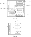
FIG. 2 is a schematic structural diagram of an integrated low-voltage connector in an integrated controller according to an embodiment of the present disclosure. -
FIG. 3 is a schematic structural diagram after integrating a low-voltage signal in an integrated controller according to an embodiment of the present disclosure. -
FIG. 4 is a schematic structural diagram of an integrated inlet filter unit in an integrated controller according to an embodiment of the present disclosure. -
FIG. 5 is a schematic structural diagram of an electric drive assembly according to an embodiment of the present disclosure. -
FIG. 6 is a schematic structural diagram of a vehicle according to an embodiment of the present disclosure. -
-
Integrated controller 10;Electric drive assembly 20;Vehicle 30; -
Box 1;Control unit 2; Charging/discharging conversion unit 3; High-voltage interface assembly 4; Low-voltage connector 5;First power unit 6;Second power unit 7;Inlet filter unit 8; - First digital
signal processing chip 11; Second digitalsignal processing chip 12; Third digitalsignal processing chip 13; - First high-
voltage interface 41; Second high-voltage interface 42; Third high-voltage interface 43; -
Motor 201;Motor drive module 202;Power battery 301. - The embodiments of the present invention are described in detail below, and the embodiments described with reference to accompanying drawings are exemplary.
- In order to resolve the above problem, an embodiment of a first aspect of the present disclosure provides an integrated controller. The integrated controller may cancel arrangement of a high-voltage distribution box, which reduces a demand for a high-voltage wiring harness, reduces costs, and saves vehicle space.
- An integrated controller according to the embodiments of the present disclosure is described below with reference to
FIG. 1 to FIG. 4 . - As shown in
FIG. 1 , theintegrated controller 10 includes abox 1, acontrol unit 2, a charging/discharging conversion unit 3, and a high-voltage interface assembly 4. - The
control unit 2 and the charging/discharging conversion unit 3 are arranged in thebox 1. That is to say, thecontrol unit 2 and the charging/discharging conversion unit 3 use thesame box 1, so that use of the box may be reduced in structure, degree of integration may be improved, occupied space may be saved, and costs may be reduced. - The high-
voltage interface assembly 4 includes a high-voltage interface arranged on thebox 1 and a high-voltage connection member arranged in thebox 1. The high-voltage connection member is connected with the high-voltage interface, thecontrol unit 2, and the charging/discharging conversion unit 3 to receive and distribute a high-voltage battery signal. Specifically, a high-voltage distribution box exists for an original high-voltage power distribution design of the vehicle. A high-voltage power requires to enter the high-voltage distribution box through the high-voltage interface. The high-voltage distribution box divides the high-voltage power into multiple branches, each of which is outputted by a different high-voltage interface after passing through a different safety and contactor, thereby completing high-voltage power distribution for another module outside the high-voltage distribution box. Different from the original high-voltage power distribution design of the vehicle, the embodiment of the present disclosure is provided with a high-voltage interface assembly 4, and thecontrol unit 2 and the charging/dischargingconversion unit 3 are arranged in thebox 1, and are all connected to the high-voltage connection member arranged in thebox 1. Therefore, a high-voltage wiring harness connected to thecontrol unit 2 and the charging/dischargingconversion unit 3 share thesame box 1 thecontrol unit 2 and the charging/dischargingconversion unit 3. That is to say, in the embodiment of the present disclosure, a part of the high-voltage distribution box that distributes power to the high-voltage power in the original high-voltage power distribution design of the vehicle, that is, the high-voltage connection member, and another module outside the high-voltage distribution box, that is, thecontrol unit 2 and the charging/dischargingconversion unit 3 are partially recombined to be integrated and placed in thebox 1. With this design, the arrangement of the high-voltage distribution box may be canceled, space may be saved, and the corresponding high-voltage interface for high-voltage power distribution between thecontrol unit 2 and the charging/dischargingconversion unit 3 does not need to be designed, the demand for high-voltage connection members and high-voltage wiring harnesses may be reduced, and the costs may be reduced. - According to the
integrated controller 10 in an embodiment of the present disclosure, thecontrol unit 2 and the charging/dischargingconversion unit 3 are provided with thesame box 1, which reduces use of structural parts and saves costs. In addition, the high-voltage interface assembly 4 is configured to be connected to thecontrol unit 2 and the charging/dischargingconversion unit 3, which may reduce the demand for high-voltage connection members and high-voltage wiring harnesses, and cancel the arrangement of the high-voltage distribution box, save space, and reduce costs. - In some embodiments, the
control unit 2 includes a motor controller, a vehicle controller, and a battery management controller. In other words, the motor controller, the vehicle controller, and the battery management controller are highly integrated, which may not only reduce volume of the assembly, reduce demand for signal wiring harness, but also shorten interaction time and improve efficiency. In addition, the charging/dischargingconversion unit 3 includes a direct current (DC) conversion unit and a vehicle-mounted charging unit and an on-board charging unit. In other words, the DC conversion unit and the on-board charging unit are integrated to reduce an assembly volume and improve a degree of integration. Therefore, the above integration manner is also conducive to reuse a subsequent structure or module, and improve a reuse degree of theintegrated controller 10. - In some embodiments, as shown in
FIG. 1 , the high-voltage interface assembly 4 includes a first high-voltage interface 41, a second high-voltage interface 42, and a third high-voltage interface 43 arranged on the box, and a first connection member, a second connection member, a third connection member, and a fourth connection member. - The first high-
voltage interface 41 is configured to receive the high-voltage battery signal. The first connection member is connected with the first high-voltage interface 41 and the second high-voltage interface 42. The second connection member is connected with the DC conversion unit and the on-board charging unit. The third connection member is connected with the motor controller. The fourth connection member is connected with the first high-voltage interface 41 and the third high-voltage interface 43. - Specifically, different from the original high-voltage power distribution design of the vehicle, the embodiment of the present disclosure divides the relevant parts in the original high-voltage distribution box into two. As shown in
FIG. 1 , a part of the high-voltage distribution box is arranged in a high-voltage battery of the vehicle and connected to the power battery, and the other part is connected to thecontrol unit 2 and the charging/dischargingconversion unit 3 and placed in thebox 1. As a result, during high-voltage power distribution, the high-voltage power, that is, the high-voltage battery signal, is outputted through the high-voltage interface of a fuse K1 and a high-voltage battery terminal, and is conveyed to the first high-voltage interface 41 by the connected high-voltage wiring harness. The first high-voltage interface 41 divides the high-voltage battery signal into four. In other words, the high-voltage power is distributed to the motor controller of thecontrol unit 2, and the DC conversion unit and the on-board charging unit in thebox 1 are distributed to the high-voltage power through a fuse K3, and are outputted to the second high-voltage interface 42 through a fuse K2. The high-voltage wiring harness distributes power to an air conditioner outside thebox 1 through the high-voltage interface at an air conditioner terminal, and controls output to the third high-voltage interface 43 through the positive and negative contactors to distribute power to the DC charging port outside thebox 1. Therefore, through the above all-in-one integrated design, the embodiment of the present disclosure cancels arrangement of the high-voltage distribution box, and reduces use of the high-voltage interface and the high-voltage wiring harness when thecontrol unit 2 and the charging/dischargingconversion unit 3 perform high-voltage power distribution, which shortens length of the wiring harness between different modules, and saves costs and space. - In an implementation, as shown in
FIG. 2 , theintegrated controller 10 further includes a low-voltage connector 5. - The low-
voltage connector 5 is arranged in thebox 1. The low-voltage connector 5 is connected with thecontrol unit 2 and the charging/dischargingconversion unit 3 receive a low-voltage power signal and transmit a communication signal. Specifically, in the original low-voltage design of the vehicle, each module is provided with an independent controller, so that each module requires to be provided with a low-voltage connector separately to exchange information with external signals. However, in the embodiment of the present disclosure, all low-voltage connectors in the original low-voltage design of the vehicle are combined into one. In other words, after the motor controller, the vehicle controller, and the battery management controller are integrated into thecontrol unit 2, and the DC conversion unit and the on-board charging unit are integrated into the charging/dischargingconversion unit 3, thecontrol unit 2 and the charging/dischargingconversion unit 3 use the same low-voltage connector 5. As a result, the low-voltage power signal and the transmitted communication signal are divided into two after being inputted by the low-voltage connector 5, so as to respectively supply power and signal interactive communication for thecontrol unit 2 and the charging/dischargingconversion unit 3. Based on design, use of the low-voltage wiring harnesses and the low-voltage interfaces can be reduced, and costs can be reduced. - In some embodiments, as shown in
FIG. 3 , the motor controller, the vehicle controller, and the battery management controller are integrated in a first digitalsignal processing chip 11; the DC conversion unit is arranged on a second digitalsignal processing chip 12; and the on-board charging unit is arranged on a third digitalsignal processing chip 13. - In other words, in the original low-voltage design of the vehicle, each module is provided with a separate digital signal processing chip for signal acquisition and control. However, in the embodiment of the present disclosure, after the motor controller, the vehicle controller, and the battery management controller are integrated into the
control unit 2, and the DC conversion unit and the on-board charging unit are integrated into the charging/dischargingconversion unit 3, when the resources are satisfied, the motor controller, the vehicle controller, and the battery management controller are designed to combine and use the first digitalsignal processing chip 11. In this way, quantities of digital signal processing chips used may be reduced, costs may be saved, and occupied space may be reduced. - Specifically, as shown in
FIG. 2 , in the embodiment of the present disclosure, all low-voltage connectors in the original low-voltage design of the vehicle are combined, and the low-voltage power signal and the transmitted communication signal transmitted by thecontrol unit 2 and the charging/dischargingconversion unit 3 are all inputted by the interface of the same low-voltage connector 5, so that quantities of the low-voltage connectors used may be saved. In addition, on the premise that the received low-voltage power signal and the transmitted communication signal are the same, the different modules in thecontrol unit 2 and the charging/dischargingconversion unit 3 can share the same interface pin input. In other words, the embodiment of the present disclosure changes the way in which the original different modules acquire the required communication signals to the same sampling channel for the same communication signal between different modules. That is to say, the same communication signal is transmitted by the same pin of the low-voltage connector 5 and transmitted to different modules, so that quantities of pins of the low-voltage connector 5 can be reduced and costs can be saved. - In the embodiment, as shown in
FIG. 3 , for the same transmitted communication signal externally transmitted, the low-voltage connector 5 only designs one sampling channel for signal acquisition, and sends the acquired signals to different digital signal processing chips for information processing. For example, for CAN communication of a power network, the low-voltage connector 5 is provided with a fixed connector for external connection. In other words, the power network CAN communication signal is only received by the connector. The low-voltage connector 5 divides the received power network CAN communication signal into three and respectively transmitted to the first digitalsignal processing chip 11, the second digitalsignal processing chip 12, the third digitalsignal processing chip 13, so that the vehicle controller, the DC conversion unit, and the on-board charging unit can simultaneously receive the CAN communication signal of the power network. For an alternating current (AC) charging CC signal, this signal is an acquisition signal provided to both the on-board charging unit and the battery management controller. After integration, the transmission of the signal is combined into a connector interface, and one acquisition channel is used. In other words, the signal only requires to be inputted through one signal of the low-voltage connector 5, and is divided into two and respectively transmitted to the on-board charging unit and the battery management controller, so that the battery management controller and the on-board charging unit perform corresponding operations based on the signal, such as status information of detecting whether a charging gun is connected. For a collision signal or a bus voltage sampling signal or a water temperature sampling signal, the signal requires to be separately transmitted to the motor controller, the vehicle controller, and the battery management controller before integration. However, after the motor controller, the vehicle controller, and the battery management controller are integrated into the first digitalsignal processing chip 11, the transmission of the signal can be combined by using the interface of the same low-voltage connector 5, and can be transmitted to the integrated first digitalsignal processing chip 11 through one acquisition channel. In this way, the vehicle controller can learn whether the vehicle has a collision based on the collision signal, learn a voltage value of the power battery based on the bus voltage sampling signal, and learn a heat dissipation situation of a heat dissipation system and control of a water pump based on the water temperature sampling signal. Therefore, unlike the design in which each module in the original vehicle uses a separate device, the present embodiment achieves the low cost, small volume, and light weight by reusing the low-voltage connector 5 and the low-voltage interface. - In an implementation, as shown in
FIG. 2 , theintegrated controller 10 further includes afirst power unit 6 and asecond power unit 7. - The
first power unit 6 is connected with the first digitalsignal processing chip 11 to convert the low-voltage power signal into a power supply signal provided to the first digitalsignal processing chip 11. Thesecond power unit 7 is connected with the second digitalsignal processing chip 12 and the third digitalsignal processing chip 13 to convert the low-voltage power signal into a power supply signal provided to the second digitalsignal processing chip 12 and the third digitalsignal processing chip 13. - That is to say, different from the design in which each module is provided with a separate power in the original vehicle, as shown in
FIG. 2 , in the embodiment of the present disclosure, after the motor controller, the vehicle controller, and the battery management controller are integrated into thecontrol unit 2, and the DC conversion unit and the on-board charging unit are integrated into the charging/dischargingconversion unit 3, the original power supply mode for different modules is changed to a mode by reusing the same voltage power for multiple modules. Specifically, the low-voltage power signals are all connected from the low-voltage connector 5, and are divided into two and respectively transmitted to thefirst power unit 6 and thesecond power unit 7. Thefirst power unit 6 converts the low-voltage power signal to the power for the first digitalsignal processing chip 11 to supply power to thecontrol unit 2. Thesecond power unit 7 converts the low-voltage power signal into the power for the second digitalsignal processing chip 12 and the third digitalsignal processing chip 13 to supply power to the charging/dischargingconversion unit 3. In this way, in the embodiment of the present disclosure, by combining the plurality power modules in the original vehicle design into thefirst power unit 6 and thesecond power unit 7, demand for the power module structural components can be reduced, costs can be reduced, and volume can be reduced to save the vehicle space. - In an implementation, as shown in
FIG. 2 orFIG. 4 , theintegrated controller 10 further includes aninlet filter unit 8. - The
inlet filter unit 8 is connected with the low-voltage connector 5, thefirst power unit 6, and thesecond power unit 7 to filter the low-voltage power signal. - Specifically, in the original low-voltage design of the vehicle, a separate inlet filter protection circuit is provided for each module. In the embodiment of the present disclosure, the multiple inlet filter protection circuits in the original vehicle design are combined into one
inlet filter unit 8, that is, each module in theintegrated controller 10 shares the sameinlet filter unit 8. For example, as shown inFIG. 4 , the low-voltage battery power of a passenger vehicle is 12 V, and all modules on the vehicle are powered from the 12 V power supply. The low-voltage power signal enters through the low-voltage connector 5 and is uniformly inputted to theinlet filter unit 8. Theinlet filter unit 8 performs inlet protection filtering processing on a low-voltage power signal, such as an inlet TVS tube, an anti-reverse diode, an inlet electrolytic capacitor, an inlet ceramic capacitor, a magnetic bead, a differential mode inductor, a common mode inductor and another circuit processing. The processed low-voltage power signal is transmitted to thefirst power unit 6 and thesecond power unit 7 to supply low-voltage power to different modules in theintegrated controller 10. Based on the above, the design can not only effectively avoid inlet interference, lightning strikes, surges, and the like, but also reduce design of the inlet filter protection circuit, and saves costs and space. - In summary, according to the
integrated controller 10 of the embodiment of the present disclosure, the motor controller, the vehicle controller, and the battery management controller are integrated into thecontrol unit 2, and the DC conversion unit and the on-board charging unit are integrated into the charging/dischargingconversion unit 3. As a result, arrangement of the high-voltage distribution box may be canceled, demand for the high-voltage connection members and the high-voltage wiring harnesses can be reduced, and thesame box 1 may be shared, design of the module housing and the related support frames can be reduced, and the low-voltage connectors 5 may be shared, saving the low voltage wiring harness and the low voltage interface. In addition, the power unit and the acquisition channel can be reused between different modules by using the same power and acquiring the same signal, and the power module and the signal wiring harness are not required to separately design. - A second aspect of an embodiment of the present disclosure provides an electric drive assembly. As shown in
FIG. 5 , theelectric drive assembly 20 includes anintegrated controller 20 provided by the embodiments, amotor 301, and a motor drive module 302. - The
integrated controller 20 is configured to send a heating control signal when it is determined that a vehicle has a heating demand; and the motor drive module 302 is connected with theintegrated controller 20 and themotor 301 to drive the motor to generate heat in response to the heating control signal. In other words, the embodiment of the present disclosure uses theintegrated controller 10 integrated in the above embodiment, and shares themotor 301 and the motor drive module 302 for each module in theintegrated controller 10, so as to realize the function of heating the battery in a low temperature environment, and a heating module is not required to separately design for heating the battery, and costs of the vehicle are further saved. - Specifically, as shown in
FIG. 5 , the heating of the high-voltage battery in the embodiment of the present disclosure directly reuses theintegrated controller 10 and the motor drive module 302 of theelectric drive assembly 20. Theintegrated controller 10 outputs a proportion of a reactive current or outputs all the reactive current during locked-rotor heating, so that the motor drive module 302 and the motor winding are heated, so that in a low temperature environment, a water temperature rises, and the high-voltage battery is heated by a water circulation system of the vehicle. - Referring to
FIG. 5 , theelectric drive assembly 20 is mainly divided into the following three operating conditions. - The
electric drive assembly 20 is in a normal drive mode, and theintegrated controller 10 outputs id = 0 and iq = Imax during software control, so as to ensure a maximum output torque at a shaft end to drive the vehicle to normally travel. In the low temperature environment, in order to ensure good performance of the battery, the battery requires to be heated. That is to say, the battery is heated by reusing the motor drive module 302, heat is generated by using themotor 301, and the battery is heated through a thermal circulation system. Heating by using the motor drive module 302 is divided into two modes: heating while traveling and locked-rotor heating. The traveling heating is usually performed under medium and small torques. Theintegrated controller 10 controls id to increase and iq to decrease, so as to increase the total current and realize heating while ensuring the same output torque at the shaft end. The locked-rotor heating is in a case of parking. Theintegrated controller 10 controls id = Imax, and iq = 0, so as to ensure that the output torque of the shaft end is 0, and the motor is heated by three-phase DC heating. - According to the
electric drive assembly 20 in the embodiment of the present disclosure, the motor drive module 302 is controlled by the motor controller through theintegrated controller 10, and the function of heating the battery in a low temperature environment can be realized by using heating while traveling and locked-rotor heating. The heating module is not required to separately design for heating the battery, and costs of the vehicle are further saved. - In some embodiments, the
electric drive assembly 20 also includes a speed reducer. The speed reducer is connected with theintegrated controller 10. That is to say, structurally, thesame motor 301 and the speed reducer are used for different modules in theintegrated controller 10, so that use of structural parts can be reduced, costs of the vehicle can be reduced, assembly volume can be reduced, and weight can be reduced through structural reuse. - A third aspect of the present disclosure provides a vehicle. The vehicle in the embodiment of the present disclosure is described below.
- In an embodiment of the present disclosure, the
vehicle 30 includes apower battery 301 and anintegrated controller 10 provided by the embodiment, and thepower battery 301 is connected with theintegrated controller 10. - In this embodiment, a specific implementation of the
vehicle 30 is similar to a specific implementation of theintegrated controller 10 of any of the embodiments of the present disclosure. For details, refer to the descriptions of theintegrated controller 10. In order to reduce redundancy, details are not described herein again. - In another embodiment of the present disclosure, as shown in
FIG. 6 , thevehicle 30 includes apower battery 301 and theelectric drive assembly 20 provided by the embodiment. - In an embodiment, the AC charging port passes through a power factor correction (PFC) circuit, to realize a bidirectional conversion function of converting 220 V AC to DC or converting DC to AC. In addition, a primary side of a transformer of the on-board charging unit is shared, and one more winding is added to s secondary side. In this way, an output function of the DC conversion unit can be realized at the same time.
- The charging manners for the
vehicle 30 are divided into DC charging and AC charging. During the DC charging, the current flows to thepower battery 301 from a charging pile through a power distribution part of theelectric drive assembly 20 to charge thepower battery 301. During the AC charging, the current is converted from 220 V household electricity to thepower battery 301 for charging by the on-board charging unit in theelectric drive assembly 20. When thevehicle 30 is normally driven, the current flows from thepower battery 301 to the motor through the motor controller in theelectric drive assembly 20 to drive thevehicle 30 to operate normally. Heating is divided into heating while traveling and locked-rotor heating. The heating while traveling means that during normal driving of thevehicle 30, the motor controller controls, through a PWM wave, a part of the current to output useful work to drive thevehicle 30 to travel and a part of the current to output useless work, and the current flows through the motor controller and the motor, so that a coil of the motor generates heat, to heat a coolant and finally heat thepower battery 301. - According to the
vehicle 30 in the embodiment of the present disclosure, by using the integratedcontroller 10 or theelectric drive assembly 20 provided by the embodiment, the vehicle integration and the reuse degree can be improved, costs of the vehicle can be reduced, and the vehicle space can be saved. - In the description of this specification, the description of the reference terms such as "an embodiment", "some embodiments", "exemplary embodiments", "example", "specific example", or "some examples" means that the specific features, structures, materials, or characteristics described with reference to the embodiment or example are included in at least one embodiment or example of the present disclosure. In the present disclosure, exemplary descriptions of the foregoing terms do not necessarily refer to the same embodiment or example.
- Although the embodiments of the present disclosure have been shown and described, a person of ordinary skill in the art should understand that various changes, modifications, replacements, and variations may be made to the embodiments without departing from the principles and spirit of the present disclosure, and the scope of the present disclosure is as defined by the appended claims and their equivalents.
Claims (10)
- An integrated controller, comprising:a box;a control unit and a charging/discharging conversion unit that are arranged in the box; anda high-voltage interface assembly, comprising a high-voltage interface arranged on the box and a high-voltage connection member arranged in the box, the high-voltage connection member being connected with the high-voltage interface, the control unit, and the charging/discharging conversion unit to receive and distribute a high-voltage battery signal.
- The integrated controller according to claim 1, wherein the control unit comprises a motor controller, a vehicle controller, and a battery management controller; and the charging/discharging conversion unit comprises a direct current (DC) conversion unit and an on-board charging unit.
- The integrated controller according to claim 1 or 2, whereinthe high-voltage interface assembly comprises a first high-voltage interface, a second high-voltage interface, and a third high-voltage interface arranged on the box, and a first connection member, a second connection member, a third connection member, and a fourth connection member;wherein the first high-voltage interface is configured to receive the high-voltage battery signal; the first connection member is connected with the first high-voltage interface and the second high-voltage interface; the second connection member is connected with the DC conversion unit and the on-board charging unit; the third connection member is connected with the motor controller; and the fourth connection member is connected with the first high-voltage interface and the third high-voltage interface.
- The integrated controller according to any of claims 1 to 3, further comprising:
a low-voltage connector, arranged in the box, connected with the control unit and the charging/discharging conversion unit to receive a low-voltage power signal and a transmission communication signal. - The integrated controller according to any of claims 1 to 4, whereinthe motor controller, the vehicle controller, and the battery management controller are integrated in a first digital signal processing chip;the DC conversion unit is arranged on a second digital signal processing chip; andthe on-board charging unit is arranged on a third digital signal processing chip.
- The integrated controller according to any of claims 1 to 5, further comprising:a first power unit, connected with the first digital signal processing chip to convert the low-voltage power signal into a power supply signal provided to the first digital signal processing chip; anda second power unit, connected with the second digital signal processing chip and the third digital signal processing chip to convert the low-voltage power signal into a power supply signal provided to the second digital signal processing chip and the third digital signal processing chip.
- The integrated controller according to any of claims 1 to 6, further comprising:
an inlet filter unit, connected with the low-voltage connector, the first power unit, and the second power unit to filter the low-voltage power signal. - An electric drive assembly, comprising:the integrated controller according to any of claims 1 to 7, configured to send a heating control signal when it is determined that a vehicle has a heating demand; anda motor and a motor drive module, the motor drive module being connected with the integrated controller and the motor to drive the motor to generate heat in response to the heating control signal.
- The electric drive assembly according to claim 8, further comprising a speed reducer, the speed reducer being connected with the integrated controller.
- A vehicle,comprising a power battery and the integrated controller according to any of claims 1 to 7, the power battery being connected with the integrated controller;or comprising a power battery and the electric drive assembly according to claim 8 or 9.
Applications Claiming Priority (2)
| Application Number | Priority Date | Filing Date | Title |
|---|---|---|---|
| CN202110889134.3A CN115703366B (en) | 2021-08-04 | 2021-08-04 | Integrated controller, electric drive assembly and vehicle |
| PCT/CN2022/099423 WO2023011018A1 (en) | 2021-08-04 | 2022-06-17 | Integrated controller, electric drive assembly, and vehicle |
Publications (2)
| Publication Number | Publication Date |
|---|---|
| EP4342718A1 true EP4342718A1 (en) | 2024-03-27 |
| EP4342718A4 EP4342718A4 (en) | 2024-10-16 |
Family
ID=85154241
Family Applications (1)
| Application Number | Title | Priority Date | Filing Date |
|---|---|---|---|
| EP22851734.8A Pending EP4342718A4 (en) | 2021-08-04 | 2022-06-17 | INTEGRATED CONTROL DEVICE, ELECTRIC DRIVE ASSEMBLY AND VEHICLE |
Country Status (9)
| Country | Link |
|---|---|
| US (1) | US12617304B2 (en) |
| EP (1) | EP4342718A4 (en) |
| JP (1) | JP7714688B2 (en) |
| KR (1) | KR20240004915A (en) |
| CN (1) | CN115703366B (en) |
| AU (1) | AU2022322688B2 (en) |
| BR (1) | BR112023027433A2 (en) |
| CA (1) | CA3224326A1 (en) |
| WO (1) | WO2023011018A1 (en) |
Families Citing this family (5)
| Publication number | Priority date | Publication date | Assignee | Title |
|---|---|---|---|---|
| KR20240136016A (en) * | 2023-03-06 | 2024-09-13 | 한온시스템 주식회사 | Integrated controller for vehicle |
| CN118399517A (en) * | 2023-05-10 | 2024-07-26 | 比亚迪股份有限公司 | Power module, chip, system, method and vehicle |
| FR3157023A1 (en) * | 2023-12-19 | 2025-06-20 | Commissariat à l'énergie atomique et aux énergies alternatives | Heat production system |
| WO2026019253A1 (en) * | 2024-07-17 | 2026-01-22 | 한온시스템 주식회사 | Integrated controller and thermal management system including same |
| CN119705119B (en) * | 2024-12-26 | 2025-10-03 | 长城汽车股份有限公司 | Power control system and vehicle |
Family Cites Families (30)
| Publication number | Priority date | Publication date | Assignee | Title |
|---|---|---|---|---|
| KR101023885B1 (en) * | 2008-11-27 | 2011-03-22 | 현대자동차주식회사 | Car cushion box |
| JP5259752B2 (en) * | 2011-02-04 | 2013-08-07 | 株式会社日立製作所 | Vehicle travel motor control device and vehicle equipped with the same |
| WO2013097824A1 (en) * | 2011-12-31 | 2013-07-04 | 深圳市比亚迪汽车研发有限公司 | Electric vehicle and power system and motor controller for electric vehicle |
| CN204184209U (en) * | 2014-08-26 | 2015-03-04 | 比亚迪股份有限公司 | Vehicle control system and the vehicle with it |
| JP6597996B2 (en) * | 2015-03-31 | 2019-10-30 | 株式会社 神崎高級工機製作所 | Motor unit for moving body |
| JP5919422B1 (en) * | 2015-05-18 | 2016-05-18 | カルソニックカンセイ株式会社 | Power converter |
| CN205256048U (en) * | 2015-12-03 | 2016-05-25 | 北京新能源汽车股份有限公司 | Electric automobile and control system thereof |
| WO2017179153A1 (en) * | 2016-04-13 | 2017-10-19 | 三菱電機株式会社 | Charger/discharger |
| HUE060485T2 (en) * | 2016-06-07 | 2023-03-28 | Tesla Inc | Electric motor cooling system |
| CN206953969U (en) * | 2017-05-26 | 2018-02-02 | 深圳市大地和电气股份有限公司 | A kind of New-energy electric vehicle power assembly |
| CN107128159A (en) * | 2017-05-26 | 2017-09-05 | 深圳市大地和电气股份有限公司 | A kind of New-energy electric vehicle power assembly |
| KR102539784B1 (en) | 2017-10-30 | 2023-06-08 | 엘지이노텍 주식회사 | Vehicle control apparatus |
| CN107640061A (en) * | 2017-11-07 | 2018-01-30 | 北京华田汽车科技有限公司 | A kind of multiple field integrated power control unit |
| DE102018104914A1 (en) * | 2018-03-05 | 2019-09-05 | Dr. Ing. H.C. F. Porsche Aktiengesellschaft | Integrated power box |
| CN110549872A (en) * | 2018-03-27 | 2019-12-10 | 北京华田汽车科技有限公司 | Electric automobile high-voltage electrical framework adopting standard battery pack and integrated power control unit |
| US10737584B2 (en) * | 2018-10-18 | 2020-08-11 | Ford Global Technologies, Llc | Battery state of charge reset |
| CN209351255U (en) * | 2018-11-16 | 2019-09-06 | 北京理工华创电动车技术有限公司 | A kind of electric car power integrated controller device |
| JP2022517717A (en) * | 2018-11-29 | 2022-03-10 | クラブ カー エルエルシー | Auxiliary power output for battery management system |
| JP7201487B2 (en) * | 2019-03-15 | 2023-01-10 | マレリ株式会社 | power control unit |
| CN110091814A (en) * | 2019-04-28 | 2019-08-06 | 南京航智电动科技有限公司 | A kind of fully integrated system of electric car and application |
| CN110962692B (en) * | 2019-06-24 | 2020-12-11 | 宁德时代新能源科技股份有限公司 | Battery pack heating system and control method thereof |
| CN112389267B (en) * | 2019-08-15 | 2023-01-10 | 比亚迪股份有限公司 | Electric vehicles and their integrated controllers, integrated control systems |
| CN210970721U (en) * | 2019-08-28 | 2020-07-10 | 比亚迪股份有限公司 | Electric vehicle and its on-board charger |
| CN213007972U (en) * | 2020-06-30 | 2021-04-20 | 北汽福田汽车股份有限公司 | Charging circuit and vehicle |
| CN112092680A (en) | 2020-09-14 | 2020-12-18 | 珠海格力电器股份有限公司 | High-voltage integrated controller of fuel cell, fuel cell and automobile |
| CN114312340B (en) * | 2020-09-30 | 2024-04-16 | 比亚迪股份有限公司 | Central controller and vehicle |
| CN113022326B (en) | 2021-03-31 | 2022-03-18 | 比亚迪股份有限公司 | Vehicle electric drive system control method, electric drive system and vehicle |
| CN112977002B (en) * | 2021-05-11 | 2021-10-22 | 比亚迪股份有限公司 | Integrated thermal management system, vehicle and thermal management control method |
| CN115917836B (en) * | 2021-08-05 | 2024-01-30 | 宁德时代新能源科技股份有限公司 | Charge and discharge circuits, systems and control methods |
| CN116096602B (en) * | 2021-11-15 | 2025-09-02 | 宁德时代新能源科技股份有限公司 | Battery heating circuit and control method thereof, battery and electric vehicle |
-
2021
- 2021-08-04 CN CN202110889134.3A patent/CN115703366B/en active Active
-
2022
- 2022-06-17 JP JP2023572063A patent/JP7714688B2/en active Active
- 2022-06-17 EP EP22851734.8A patent/EP4342718A4/en active Pending
- 2022-06-17 KR KR1020237041733A patent/KR20240004915A/en active Pending
- 2022-06-17 WO PCT/CN2022/099423 patent/WO2023011018A1/en not_active Ceased
- 2022-06-17 BR BR112023027433A patent/BR112023027433A2/en unknown
- 2022-06-17 CA CA3224326A patent/CA3224326A1/en active Pending
- 2022-06-17 AU AU2022322688A patent/AU2022322688B2/en active Active
-
2023
- 2023-11-30 US US18/524,205 patent/US12617304B2/en active Active
Also Published As
| Publication number | Publication date |
|---|---|
| US12617304B2 (en) | 2026-05-05 |
| WO2023011018A1 (en) | 2023-02-09 |
| JP2024530382A (en) | 2024-08-21 |
| CN115703366B (en) | 2025-09-09 |
| CN115703366A (en) | 2023-02-17 |
| US20240092201A1 (en) | 2024-03-21 |
| KR20240004915A (en) | 2024-01-11 |
| BR112023027433A2 (en) | 2024-03-12 |
| AU2022322688A1 (en) | 2024-01-18 |
| CA3224326A1 (en) | 2023-02-09 |
| AU2022322688B2 (en) | 2025-09-11 |
| EP4342718A4 (en) | 2024-10-16 |
| JP7714688B2 (en) | 2025-07-29 |
Similar Documents
| Publication | Publication Date | Title |
|---|---|---|
| US12617304B2 (en) | Integrated controller, electric drive assembly, and vehicle | |
| US20240246433A1 (en) | Charging and discharging apparatus and vehicle | |
| US11316434B2 (en) | Electric power conversion apparatus | |
| US11318851B2 (en) | Energy system for an electrically-driven vehicle | |
| CN104471850A (en) | Includes three-port multi-directional converter and a single transformer for electric vehicles | |
| CN104302506B (en) | Motor vehicles with high-voltage power supply systems | |
| JP7192490B2 (en) | Electric car | |
| EP4074540B1 (en) | Energy conversion apparatus, motor, power system, and vehicle | |
| IT201800006790A1 (en) | AUXILIARY POWER SUPPLY SYSTEM FOR HIGH POWER LOADS IN A HYBRID / ELECTRIC VEHICLE | |
| KR20110137675A (en) | Charging station for fast charging and adjusting the charging capacity of electric drive vehicles | |
| CN217892528U (en) | Direct current charging system for electric automobile | |
| KR20120069859A (en) | Mobile charge system | |
| WO2026045721A1 (en) | Electric rail locomotive battery system | |
| CN118399739A (en) | Capacitive filter integrated module, power supply device, power assembly and electric vehicle | |
| CN117578683A (en) | All-in-one electric drive power supply system and design method thereof | |
| WO2025195284A1 (en) | All-in-one power supply device, power assembly, and electric vehicle | |
| CN119953180A (en) | Vehicle-mounted power supply device, power assembly and electric vehicle | |
| CN219706700U (en) | Charging device and vehicle | |
| CN218040888U (en) | Power conversion system for vehicle battery pack | |
| CN214420201U (en) | Automatically controlled integrated device, equipment and vehicle | |
| CN221340214U (en) | Motor controller assembly integrating power distribution function and automobile | |
| EP4596294A1 (en) | Integrated controller for vehicle, integrated control system, and vehicle | |
| CN223798148U (en) | All-in-one power distribution unit | |
| CN110970958A (en) | Charger for medium-low speed maglev train | |
| CN222698450U (en) | Vehicle low-voltage hybrid power supply architecture and automobile |
Legal Events
| Date | Code | Title | Description |
|---|---|---|---|
| STAA | Information on the status of an ep patent application or granted ep patent |
Free format text: STATUS: THE INTERNATIONAL PUBLICATION HAS BEEN MADE |
|
| PUAI | Public reference made under article 153(3) epc to a published international application that has entered the european phase |
Free format text: ORIGINAL CODE: 0009012 |
|
| STAA | Information on the status of an ep patent application or granted ep patent |
Free format text: STATUS: REQUEST FOR EXAMINATION WAS MADE |
|
| 17P | Request for examination filed |
Effective date: 20231221 |
|
| AK | Designated contracting states |
Kind code of ref document: A1 Designated state(s): AL AT BE BG CH CY CZ DE DK EE ES FI FR GB GR HR HU IE IS IT LI LT LU LV MC MK MT NL NO PL PT RO RS SE SI SK SM TR |
|
| A4 | Supplementary search report drawn up and despatched |
Effective date: 20240916 |
|
| RIC1 | Information provided on ipc code assigned before grant |
Ipc: B60L 53/22 20190101ALI20240910BHEP Ipc: B60R 16/023 20060101ALI20240910BHEP Ipc: B60L 58/27 20190101ALI20240910BHEP Ipc: B60L 15/20 20060101ALI20240910BHEP Ipc: B60L 50/60 20190101AFI20240910BHEP |
|
| DAV | Request for validation of the european patent (deleted) | ||
| DAX | Request for extension of the european patent (deleted) |