EP4342334A1 - Backrest for a chair and chair - Google Patents
Backrest for a chair and chair Download PDFInfo
- Publication number
- EP4342334A1 EP4342334A1 EP23197120.1A EP23197120A EP4342334A1 EP 4342334 A1 EP4342334 A1 EP 4342334A1 EP 23197120 A EP23197120 A EP 23197120A EP 4342334 A1 EP4342334 A1 EP 4342334A1
- Authority
- EP
- European Patent Office
- Prior art keywords
- backrest
- support
- base
- support elements
- chair
- Prior art date
- Legal status (The legal status is an assumption and is not a legal conclusion. Google has not performed a legal analysis and makes no representation as to the accuracy of the status listed.)
- Pending
Links
- 239000004744 fabric Substances 0.000 claims description 3
- 239000011152 fibreglass Substances 0.000 claims description 3
- 230000008093 supporting effect Effects 0.000 description 9
- 230000008901 benefit Effects 0.000 description 4
- 210000004705 lumbosacral region Anatomy 0.000 description 4
- 230000008859 change Effects 0.000 description 2
- 238000001746 injection moulding Methods 0.000 description 2
- 239000000463 material Substances 0.000 description 2
- 239000004952 Polyamide Substances 0.000 description 1
- 230000015572 biosynthetic process Effects 0.000 description 1
- 230000001427 coherent effect Effects 0.000 description 1
- 230000008878 coupling Effects 0.000 description 1
- 238000010168 coupling process Methods 0.000 description 1
- 238000005859 coupling reaction Methods 0.000 description 1
- 230000000694 effects Effects 0.000 description 1
- 230000005489 elastic deformation Effects 0.000 description 1
- 230000003203 everyday effect Effects 0.000 description 1
- 210000000245 forearm Anatomy 0.000 description 1
- 238000009432 framing Methods 0.000 description 1
- 239000003365 glass fiber Substances 0.000 description 1
- 230000003993 interaction Effects 0.000 description 1
- 210000003205 muscle Anatomy 0.000 description 1
- 239000004033 plastic Substances 0.000 description 1
- 229920003023 plastic Polymers 0.000 description 1
- 229920002647 polyamide Polymers 0.000 description 1
- 230000011218 segmentation Effects 0.000 description 1
- 239000000243 solution Substances 0.000 description 1
- 230000003319 supportive effect Effects 0.000 description 1
- 230000007704 transition Effects 0.000 description 1
- 230000000007 visual effect Effects 0.000 description 1
Images


Classifications
-
- A—HUMAN NECESSITIES
- A47—FURNITURE; DOMESTIC ARTICLES OR APPLIANCES; COFFEE MILLS; SPICE MILLS; SUCTION CLEANERS IN GENERAL
- A47C—CHAIRS; SOFAS; BEDS
- A47C7/00—Parts, details, or accessories of chairs or stools
- A47C7/36—Support for the head or the back
- A47C7/40—Support for the head or the back for the back
Definitions
- the present application relates to a backrest for a chair according to the preamble of claim 1. Furthermore, the present application relates to a chair according to the preamble of claim 14.
- the backrest includes a base by means of which the backrest can be connected or connected to the rest of the chair.
- This connection can in particular be made with the formation of at least one axis of rotation, so that the backrest can be pivoted about the pivot axis relative to a seat element that provides a seat for a person.
- a translational movement of the backrest relative to the rest of the chair is also possible, and in particular the base can be provided and set up to interact with the rest of the chair in a translationally movable manner.
- a translational movement in the horizontal direction (“back and forth”) may be possible.
- the base can also be connected or connected to a counterpart of the chair in a force-transmitting manner, so that forces acting on the backrest can be diverted into the rest of the chair and ultimately into a surface.
- the base is not intended for a person to lean on.
- the base can, for example, extend at an angle relative to a back element of the backrest, so that the backrest as a whole is J-shaped when viewed in a side view, with an at least essentially vertical section of the backrest being formed by the back element and the oblique section being formed by the base .
- the backrest further comprises a back element, by means of which a leaning surface is provided for the back of a person sitting on the chair. This allows the person to lean against the backrest that supports the person's back.
- the back element is connected to the base in a force-transmitting manner, so that forces acting on the back element can be diverted to the base and ultimately from the base into the rest of the chair and into the ground.
- the back element comprises a plurality of individual support elements which are designed to support different areas of the back of the person sitting on the chair.
- the support elements can, for example, interact with different areas of the back of the respective person, with the support elements each having one Provide part of the backrest surface of the back element. It is conceivable that, depending on the person's sitting position, only some or all of the support elements are used to transfer forces. This depends on how the person leans against the back element or its individual support elements.
- the chair to which the backrest can be connected or is connected can in particular be an office chair.
- the chair includes a base for placement on a surface. It also includes a seat element for providing a seat on which a person sitting on the chair can sit.
- the chair further includes a backrest which provides a leaning surface to support the person sitting on the chair. It is particularly important for office chairs that it is possible to adopt an ergonomic sitting position, with office chairs typically providing a variety of adjustment options in order to be able to be adapted to the individual stature of a respective person. This can, for example and in particular, relate to the adjustability of the backrest.
- a backrest and a chair of the type described above are already known in the prior art.
- the German disclosure document is used as an example DE 10 2018 123 731 A1 referred.
- This deals with a backrest and a chair, which can in particular be an office chair.
- the aim of the document mentioned is to provide a flexibly adjustable backrest.
- it is proposed to equip the backrest with a frame-shaped support structure which is connected to a backrest element.
- the latter has at least two different materials that have different moduli of elasticity.
- backrests especially those intended for office chairs, is extremely complex as a variety of requirements must be taken into account. This applies in particular to the supporting properties of the respective backrest, which should enable the person sitting on the chair to optimally support their back while still maintaining a high degree of freedom of movement, which encourages the person to remain "active" while sitting. In particular, it is highly recommended to regularly change your sitting position in everyday life and thereby keep your body and muscles moving.
- the backrest of such a chair actually has conflicting tasks, namely to stabilize the back and at the same time maintain flexibility that allows the person's sitting position to be changed comfortably. As a component, the backrest should ideally fade into the background for the person, so that the support and load transfer occurs as subconsciously as possible and the person is automatically encouraged to change their sitting position regularly.
- the present application is therefore based on the task of providing a backrest and a chair equipped with it, which supports healthy sitting behavior of a respective person.
- the backrest is characterized in that the support elements each have a web spaced from the base and two opposite flanges, each connected to one side of the associated web.
- a central axis of the web of a respective support element typically extends horizontally or in a horizontal plane, while central axes of the flanges each extend at least substantially vertically or in a vertical plane.
- the flanges of one respective support element face the base and are connected directly or indirectly to the base.
- the web of a respective support element is arranged at ends of the associated flanges spaced from the base. In this way, the support elements each form the shape of an inverted or upside-down U with respect to the base.
- the back element is preferably designed with a plurality of U-shaped recesses, which can in particular be slot-shaped. These recesses divide the back element into the support elements or the shape of the support elements is determined by the recesses. In other words, the back element can be designed such that the support elements are separated from one another by means of the recesses and can therefore be deformed at least substantially independently of one another.
- the support elements are arranged nested relative to one another in such a way that a further outer support element frames an adjacent, further inner support element on three sides.
- the support elements are therefore arranged in a nested manner, with first, starting from the center of the backrest surface, a first, smallest, furthest inner support element and then at least one further support element external, larger second support element framing the first support element are arranged. If more than two support elements are provided, the second support element is followed further to the outside by a further, larger third support element which frames the second support element and is optionally framed in the same way by one or more further support elements.
- At least one support element extends with its flanges into a lower end section of the back element.
- the "lower end section” refers to a section of the back element which, when the backrest is used as intended, either does not come into direct contact with the person's back or only comes into contact with a lower lumbar region. If the backrest has a lumbar support, the lower end section can be located in particular below the lumbar support.
- the flanges preferably have a length measured along their respective central axis, which is at least 50%, preferably at least 70%, more preferably at least 90%, of a length of the flange measured along a respective central axis Flanges assigned web.
- the lengths of the flanges of a support element, in particular of the innermost support element correspond at least substantially to the length of the web of the same support element.
- the support elements each have different stiffnesses in relation to the base, which is caused by the different lengths of the flanges.
- this first support element is deflected relative to the base to a lesser extent under the influence of an at least essentially horizontal force acting on its web than would be the case with a further outer support element.
- a further outer support element basically has longer flanges, whereby a lever arm of a force acting on the web of the respective support element is larger in relation to the base than with a further inner support element.
- the rigidity of the back element is therefore segmented by means of the nesting of the support elements, with the support elements being deformable at least substantially independently of one another. A deformation that acts on one of the support elements therefore has no or only a very limited direct effect on the deformation of an adjacent or other remaining support element.
- the back element can thereby support a person's back as needed and in the way that is individually required for the respective person in a respective sitting position.
- the flanges of all support elements can extend into the lower end section of the back element.
- an external support element can be subjected to a strongly disproportionate force during a lateral tilting movement of the back, while, for example, an internal support element hardly comes into contact with the person's back.
- the support elements act independently of one another, the particularly heavily loaded support element is deformed relatively strongly in the presence of the acting force and thereby avoids the movement of the person. The person therefore does not perceive the back element as an obstacle to free movement, but on the contrary is encouraged to carry out a movement without any need for the Person's unpleasantly hard counter pressure is exerted on the back by the back element.
- the backrest comprises at least three, preferably exactly three, support elements.
- This number has proven to be particularly advantageous in order to support a person's back individually as needed in different areas of the back using the support elements.
- the use of three support elements compared to an alternative embodiment that comprises more than three support elements is advantageous in that the flanges of the individual support elements can be dimensioned overall in such a way that they are mechanically suitable for transferring forces, while maintaining the usual dimensions of the back element. which experience has shown to occur as a result of a person leaning on the support elements.
- such a design of the backrest can be advantageous in which at least two flanges of adjacent support elements, which are spatially assigned to one another, are brought together to form a common hyperflange in the direction of the base.
- the said flanges of the adjacent support elements which are each assigned to the same side of the respective web, are "fused” into a common flange and are therefore not guided as separate flanges up to the base.
- the portion where the flanges are united into a common flange is referred to as a "hyperflange" in the present application.
- the hyperflange is advantageously connected directly to the base.
- the hyperflange, as well as the flanges are not connected directly to the base, but rather, for example, to an intermediate section, which then, for example, then merges directly into the base.
- the intermediate section can be located in particular in a lower third, preferably a lower quarter, of the backrest. This means that the intermediate section is designed so deep on the back element that when the backrest is used as intended, it does not act as part of the backrest surface and as such is not directly subjected to forces by the back of a person leaning on it.
- the intermediate section can therefore be formed by the lower end section.
- An embodiment is advantageous in which the flanges of at least one of the support elements, preferably several support elements, more preferably all support elements, in sections in which they are present individually (that is, in sections in which they do not form part of a hyperflange), one along their respective Have a length measured along the central axis, which has at least 50%, preferably at least 70%, more preferably 90%, of a length of the respectively assigned web measured along its central axis.
- the flanges and hyperflanges preferably extend into the lower end section of the back element.
- a cross section of the hyperflange corresponds at least substantially to a sum of the cross sections of the flanges that are brought together to form the hyperflange.
- the back element comprises a total of three support elements, the flanges of the two outer support elements being brought together from one point to form a common hyperflange and the hyperflange extending to a lower end section of the back element.
- the flanges of the innermost support element also extend into the lower end section of the back element, wherein the flanges of the innermost support element are not part of the hyperflange, but extend individually over their entire length.
- the lengths of the flanges of all support elements in which they are present individually are preferably at least 50% of the length of the respective associated web.
- the same comprises at least one stiffening strut, by means of which the flanges of at least one support element are coupled to one another in addition to the respective associated web.
- the stiffening strut is preferably connected to the ends of the flanges facing the base.
- the stiffening strut as such is not part of the support elements, so that the latter have the U-shape described above.
- at least one stiffening strut is designed such that it couples the flanges of a plurality of support elements to one another. It is also conceivable that the backrest includes a plurality of stiffening struts.
- the at least one stiffening strut is oriented at least substantially parallel to the web of the respective supporting element. This creates, so to speak, a respective Support element closed at its open end facing away from the web, so that a self-contained support structure results.
- the stiffening strut can be arranged in particular in the lower end section of the back element.
- the web of the innermost support element is arranged relative to the base in such a way that a distance of said central axis measured perpendicular to a central axis of the web of the support element from a lower end of the base is at least 50%, preferably is at least 55%, more preferably at least 60%, of a total height, which in the sense of the present application is measured from the lower end of the base to an upper end of the web of the outermost support element.
- the support elements - starting with the first, innermost support element - are assigned in their function to an upper part of the back of a respective person, in particular an upper half of the back. This area is typically where the need for back support is greatest.
- the web of at least one support element is designed to be double curved in the manner of a hyperbolic paraboloid.
- This preferably applies to the webs of all supporting elements of the backrest.
- the shape described has the advantage that the respective web has a shape adapted to the shape of the back on its surface facing the back, which forms part of the backrest surface of the back element, which is perceived as particularly comfortable.
- the web of the at least one support element is concavely curved along a central axis extending from flange to flange and convexly curved along a vertical axis oriented perpendicular to the central axis.
- the back element can have a central, preferably flat, recess which is framed on three sides by the support elements.
- the recess forms a free space that determines the shape of the innermost support element.
- the shape of the innermost support element towards the middle of the back element is determined by the recess and towards the nearest, further outer support element its shape is determined by a U-shaped recess. This is also done in the exemplary embodiment below.
- the back element comprises a lumbar support, which is preferably arranged in a lower region of the backrest surface of the back element.
- This "lower area” is characterized by the fact that it is framed by all supporting elements. So it is special advantageous if the lumbar support is formed centrally or in the middle of the back element, so that the U-shaped support elements frame the lumbar support on three sides.
- the support elements mainly interact with an upper region of a respective back as explained above, while the lumbar support is intended and set up to support a lower region of the back, in particular in the region between the first and fifth lumbar vertebrae.
- the lumbar support is particularly suitable for correcting the sitting position of a person sitting on the corresponding chair and thereby preventing discomfort in the lumbar region.
- the lumbar support can in particular be inserted into a flat recess described above, which is arranged in the lower part of the back element.
- the backrest includes a lumbar support, it is particularly advantageous if this can be mounted or mounted in a non-destructively detachable manner on the rest of the backrest, preferably on the base and/or a nearest support element. In this way, the lumbar support can be assembled or dismantled if necessary, with a lumbar support in particular being able to be retrofitted if necessary.
- such a lumbar support is particularly advantageous because its position can be changed perpendicular to the backrest surface by means of an adjusting element, so that it can be adjusted as required.
- the lumbar support can be brought into supportive engagement with the back when the person leans against the backrest.
- the lumbar support is adjustable in two directions, preferably by means of adjustment in the first direction a support surface of the lumbar support at least substantially perpendicular to the backrest surface back and forth and by means of adjustment in the second direction the support surface of the lumbar support at least substantially can be adjusted up and down parallel to the backrest surface.
- the directions in which the lumbar support can be adjusted are preferably oriented perpendicular to one another.
- the backrest is formed in one piece.
- the backrest as a whole is formed in one piece, with the back element and the base being formed as a unitary part.
- the backrest can be manufactured using an injection molding process, which gives it a one-piece shape.
- This type of design is particularly advantageous because, in the absence of transitions from one component to another component, associated weak points are avoided which in practice can, for example, lead to noise as a result of relative movements of adjacent components to one another.
- the one-piece design has the advantage that the individual elements of the backrest interact in a defined manner, while in assembled backrests the quality of the connections between the components can have an influence on the interaction. With the one-piece design, such sources of error are excluded.
- At least the back element preferably the backrest as a whole, is formed from a glass fiber reinforced plastic.
- a glass fiber reinforced plastic can be, for example, polyamide with a glass fiber content of 30%.
- Such a design is particularly advantageous in order to keep the overall mass of the backrest low, with the material having a high elasticity with a low tendency to break. The result of this is that the backrest, in particular its back element, is particularly highly deformable without causing damage and/or plastic deformation.
- the back element tapers towards the base.
- the base is preferably designed to be compact, so that it can be particularly easily connected to the rest of the chair. Accordingly, it is advantageous if the back element has a taper in the direction of an end facing the base, so that the back element is at least substantially brought together to a dimension of the base at its end facing the base.
- the backrest includes a backrest cover which is pulled over the back element in such a way that it envelops at least part of the support elements. It is conceivable that the backrest cover covers all of the support elements of the back element or only a part of the support elements.
- the backrest cover can in particular be formed from a knitted fabric. Furthermore, the backrest cover is preferably formed in one piece.
- the backrest cover can have the shape of a cover that is open on one side, so that the backrest cover can be pulled over the back element particularly easily from an upper end of the back element facing away from the base.
- the backrest cover can contribute to changing the visual appearance of the back element; What may also be technically important is the supporting effect of the backrest cover, which it can exert on the back of a person sitting on the associated chair.
- the back element has one on each of its opposite lateral edges has a cheek projecting perpendicular to the rest of the backrest surface, the cheeks together giving the back element a bowl shape.
- the backrest cover can be pulled over the back element, with the backrest cover stretched between the side, opposite cheeks of the back element and is therefore suitable for absorbing forces acting perpendicular to a surface of the backrest cover.
- the backrest cover can additionally support the supporting effect of the support elements and enable the person sitting on the respective chair to sit more comfortably.
- the protruding shape of the cheeks means that the backrest cover pulled over the cheeks first comes into contact with the backrest cover with the back of a person leaning on the back element before the back comes into contact with one or more support elements, that is to say with the actual backrest surface , comes about. This is particularly advantageous for seating comfort, since at the moment of leaning the back is initially "softly" supported by the backrest cover before the support elements are activated.
- the back element is designed in the manner described above with hyper flanges, which, for example, include the flanges of two external support elements, it can be advantageous if the cheeks are formed in the area of the hyper flanges or the hyper flanges for forming the cheeks mentioned are formed on the side edges of the back element are arched.
- the back element can comprise a total of three support elements, with the mutually assigned flanges of the two outer support elements each being combined to form a hyperflange and with the hyperflanges being arched and forming the cheeks.
- the flanges of the innermost support element are preferably not part of the hyperflange and extend individually.
- the chair is characterized in that its backrest is designed according to one of claims 1 to 13.
- the backrest provides support for the back of a person sitting on the chair without restricting the person's freedom of movement.
- the chair can be, for example, an office chair, with the base frame preferably being equipped with wheels, so that the chair is particularly easy to set up can be moved on a surface. Furthermore, it can be advantageous if the chair includes armrests on which the person sitting on the chair can rest their arms, for example their forearms. According to general regulations for the design of office chairs, the chair can provide a variety of adjustment options in order to adapt it to the individual requirements of a respective person.
- the backrest is adjustable.
- the backrest can be adjustable between a rigid and a swinging state.
- the chair can have a coupling of the seat element and the backrest, which causes the seat surface of the seat element to tilt depending on an inclination of the backrest.
- the seat element is also increasingly tilted backwards as the backrest tilts backwards.
- the inclination of the seat element is preferably significantly smaller in magnitude than the inclination of the backrest. For example, a third or a quarter of the amount of inclination of the backrest can be transferred to the seat element, so that the inclination of the latter - and therefore the seat - tilts accordingly relative to the horizontal.
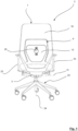
- An embodiment that is in the Figures 1 to 7 includes a chair 2, which is formed here by an office chair.
- the chair 2 includes a seat element 18, which provides a seat 19 for a person sitting on the chair 2 .
- the chair 2 includes two opposite armrests 23 arranged on the side of the seat element 18 , which are particularly good based on the Figures 1 and 2 result.
- it includes Chair 2 has a base frame 22, which in the example shown comprises a total of five sloping legs, each with a roller 30 . By means of the base frame 22, the chair 2 can be moved overall on a surface.
- the remaining elements of the chair 2 are connected to the base frame 22 to form a vertical axis of rotation 24 , so that a rotation function is provided.
- the chair 2 shown is therefore a swivel chair.
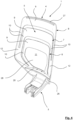
- the chair 2 also includes a backrest 1 according to the invention, which includes a back element 4 and a base 3 .
- the backrest 1 is connected to the rest of the chair 2 by means of the base 3 , as can be seen particularly well from Figure 2 results.
- the connection of the backrest 1 to the rest of the chair 2 is realized here in such a way that the backrest 1 as a whole can be pivoted about a transversely oriented pivot axis 31 relative to the chassis 22 .
- the backrest 1 is shown in a non-pivoted state.
- the back element 4 comprises a total of three support elements 6, 7, 8, which can be seen particularly well based on the Figures 3 to 7 result.
- the back element 4 forms a leaning surface 5 , which is available to a person sitting on the chair 2 to lean their back against the backrest 1 .
- the backrest 1 includes, in addition to the support elements 6, 7, 8 , a lumbar support 15, by means of which the back of a respective person can be supported in the lumbar region.
- the lumbar support 15 is arranged in a center 11 of the backrest surface 5 , with the lumbar support 15 being inserted into a central recess 28 in the example shown, which is framed on three sides by the support elements 6, 7, 8 . This is explained separately below in connection with the support elements 6, 7, 8 .
- the lumbar support 15 comprises an adjusting element 25, by means of which a position of a support surface of the lumbar support 15 can be adjusted relative to the support elements 6, 7, 8 , so that the lumbar support 15 can be tailored to the individual needs of a respective person.
- the lumbar support 15 can be adjusted in two separate directions, which in the example shown are oriented perpendicular to one another.
- the support surface of the lumbar support 15 can be moved back and forth in a direction oriented at least substantially perpendicular to the backrest surface 5 and by means of an adjustment in the second direction it can be moved up and down at least substantially parallel to the backrest surface 5 become.
- the support elements 6, 7, 8 already mentioned each include a web 9 and two flanges 10.
- the flanges 10 are connected to opposite ends of the respective web 9 , so that the support elements 6, 7, 8 each have a U-shape. Since the webs 9 are each arranged at the ends of the flanges 10 facing away from the base 3 , the U-shape of each support element 6, 7, 9 is "inverted".
- the support elements 6, 7, 8 are arranged nested relative to one another in such a way that a further outer support element 7, 8 frames a further inner support element 6, 7 on three sides. This is particularly clear from the Figures 3 and 5 .
- the support elements 6, 7, 8 together form the leaning surface 5 , which is available to a person to lean on.
- the support elements 6, 7, 8 are arranged relative to the base 3 in such a way that a distance 33 between a lower end 34 of the base 3 and a central axis 13 of the web 9 of the innermost support element 6 is here approximately 65 % of a total height 32 , which extends from the lower end 34 of the base 3 to an upper end 29 of the back element 4 .
- Figure 3 This is particularly clear from: Figure 3 .
- the arrangement described means that there is a comparatively large free space between the base 3 and the web 9 of the innermost support element 6 , in which the recess 28 is present, into which the lumbar support 15 can in turn be inserted or inserted.
- the design of the support elements 6, 7, 8 in the manner described means that the sections of the backrest surface 5 provided on the webs 9 are suitable for supporting the back in the upper back area.
- the lumbar support 15, which is arranged in height relative to the base 3 below the webs 9 of the support elements 6, 7, 8 is particularly suitable for supporting the lower back area, in particular the lumbar region.
- the outermost support element 8 therefore has the lowest rigidity of the three support elements 6, 7, 8 , which leads to the support element 8 being oriented at least essentially perpendicular to the leaning surface 5 when a force is applied to its web 9 , is deflected more relative to the base 3 than would be the case with a similar load on the web 9 of the innermost support element 6 case would be.
- the support elements 6, 7, 8 therefore behave differently under a load due to the leaning of a back on the back element 4 in that a further outer support element 7, 8 deforms more strongly under the same load than a further inner support element 6, 7.
- This is particularly advantageous for seating comfort, since typically with a greater distance from the base 3 a greater deformation in the area of the backrest surface 5 is desired in order to partially avoid the leaning back and therefore not to form a "hard” stop against the back. This maintains the person's freedom of movement as the back is not hindered in its freedom of movement.
- the flanges 10 are important for the described segmentation of the leaning surface 5 , since they are each assigned separately to the associated webs 9 of the respective support element 6, 7, 8 .
- the support elements 6, 7, 8 or in particular their webs 9 are thereby deformable essentially independently of one another, so that a load on one of the webs 9 does not directly lead to a deformation of another web 9 .
- the back element 4 can individually support the back of a respective person in different areas in a segmented manner.
- the webs 9 of the back element 4 are each shaped in the manner of a hyperbolic paraboloid, as can be seen particularly well from Figure 6 results.
- the webs 9 are therefore each designed to be double curved.
- this double curvature is designed in such a way that - viewed from a front side of the back element 4 - the webs 9 each extend along their central axis 13, which extends from flange 10 to flange 10 of the respective support element 6, 7, 8 , concave and convexly curved along their vertical axis 14, which is oriented perpendicular to the central axis 13 .
- This configuration is particularly advantageous for the seating comfort that the back element 4 offers.
- the opposite hyper flanges 12 and the flanges 10 of the innermost support element 6 on the base 3 facing ends 21 of the flanges 10 are connected to one another by means of a stiffening strut 20 .
- the support elements 6, 7, 8 indirectly connected to the base 3 by means of an intermediate section, the intermediate section being formed so deep on the back element 4 that, when the backrest 1 is used as intended, it does not act as part of the backrest surface 5 and as such does not act directly from the back of one
- the leaning person is subjected to forces or comes into contact.
- the flanges 10 therefore extend into a lower end section of the back element 4.
- this is done in such a way that the flanges 10 of the innermost support element 6 extend individually (that is, not as part of a hyper flange 12) into the lower end section of the back element 4 and the flanges of the other two support elements 7, 8 are brought together above the lower end section to form hyper flanges 12 and extend as parts of the hyper flange 12 into the lower end section.
- the individual flanges 10 of the innermost support element 6 have a length measured along their central axis, which approximately corresponds to a length of the associated web 9 measured along its central axis.
- the individual flanges 10 of the central support element 7 have a length measured along their central axis, which corresponds to approximately 50% of a length of the associated web 9 measured along its central axis.
- the individual flanges 10 of the outermost support element 8 have a length measured along their central axis, which corresponds to approximately 70% of a length of the associated web 9 measured along its central axis.
- the backrest 1 is formed as a whole in one piece, being manufactured using an injection molding process. In this way, the support elements 6, 7, 8, the intermediate section and the base 3 merge directly into one another.
- the backrest 1 is made here of a glass fiber reinforced plastic.
- the support elements 6, 7, 8 are defined by recesses which are made in the back element 4 .
- the innermost support element 6 is limited or defined towards the center 11 of the leaning surface 5 by the central recess 28 and towards the middle support element 7 by a U-shaped recess.
- the U-shaped recess is slot-shaped.
- the middle support element 7 is also defined towards the outermost support element 8 by a U-shaped recess, which is also slot-shaped here.
- the outermost support element 8 forms an outer edge of the back element 4.
- the backrest 1 has a backrest cover 16, which is shown here as an example Figures 1 and 2 is recognizable.
- the backrest cover 16 is formed from a knitted fabric that is seamless.
- At the Backrest cover 16 is a cover that is open to one side and is pulled from the upper end 29 of the back element 4 over the same. In the example shown, this is done in such a way that the two outer support elements 7, 8 are enveloped by the backrest cover 16 , while the furthest inner support element 6 remains outside the backrest cover 16 .
- the backrest cover 16 leads to the appearance of the back element 4 being unified, since the segmented design of the back element 4, which results from the individual support elements 6, 7, 8 , is optically combined to form a coherent backrest surface 5 .
- the backrest cover 16 in the example shown also fulfills a technical function. This is due to the fact that the back element 4 is formed in the area of the hyper flanges 12 with cheeks 36 protruding over the rest of the backrest surface 5 or the hyper flanges 12 are arched on the side edges of the back element 4 to form the said cheeks 36 . This is particularly clear from the Figures 4 and 6 . As a result of this configuration, the back element 4 has a shell shape, as is known from typical shell seats.
- the backrest cover 16 causes the backrest cover 16 to stretch over the cheeks 36 when it is arranged on the back element 4 .
- the backrest cover 16 is suitable for absorbing forces acting perpendicularly on its surface, forming an elastic deformation, and in this way supporting the back of a person leaning on it. Since the cheeks 36 protrude somewhat beyond the rest of the backrest surface 5 , the back of the person leaning on them first comes into contact with the backrest cover 16 when leaning on it, before the support elements 6, 7, 8 are finally activated.
- the back element 4 in the example shown comprises two grooves 26, 27, which are suitable for interacting in a form-fitting manner with correspondingly designed piping of the backrest cover 16 and thereby producing a force-transmitting connection of the backrest cover 16 to the back element 4 .
Abstract
Die vorliegende Anmeldung betrifft eine Rückenlehne (1) für einen Stuhl (2) umfassend eine Basis (3), mittels der die Rückenlehne (1) an den Stuhl (2) angeschlossen ist und ein Rückenelement (4) zur Bereitstellung einer Lehnfläche (5), wobei das Rückenelement (4) eine Mehrzahl von Stützelementen (6, 7, 8) umfasst, wobei die Stützelemente (6, 7, 8) dazu eingerichtet sind, jeweils unterschiedliche Bereiche des Rückens zu stützen wobei die Stützelemente (6, 7, 8) jeweils einen von der Basis (3) beabstandeten Steg (9) sowie zwei einander gegenüberliegende, jeweils an einer Seite des zugehörigen Stegs (9) angeschlossene Flansche (10) aufweisen, wobei die Flansche (10) eines jeweiligen Stützelements (6, 7, 8) jeweils der Basis (3) zugewandt und mit der Basis (3) verbunden sind, wobei der Steg (9) eines jeweiligen Stützelements (6, 7, 8) an von der Basis (3) beabstandeten Enden der zugehörigen Flansche (10) angeordnet ist, wobei die Stützelemente (6, 7, 8) derart relativ zueinander geschachtelt angeordnet sind, dass ein jeweils weiter außenliegendes Stützelement (7, 8) ein benachbartes, weiter innenliegendes Stützelement (6, 7) dreiseitig einrahmt.Um eine Rückenlehne sowie einen damit ausgestatteten Stuhl bereitzustellen, die ein gesundes Sitzverhalten einer jeweiligen Person unterstütz, wird vorgeschlagen, dass eine Steifigkeit des Rückenelements (4) mittels der Schachtelung der Stützelemente (6, 7, 8) segmentiert ist und die Stützelemente (6, 7, 8) zumindest im Wesentlichen unabhängig voneinander verformbar sind, wobei die Stützelemente (6, 7, 8) bezogen auf die Basis infolge unterschiedlicher Längen der Flansche (10) jeweils unterschiedliche Steifigkeiten aufweisen, sodass die Stützelemente (6, 7, 8) sich bei einer Belastung infolge der Anlehnung eines Rückens an dem Rückenelement (4) derart unterschiedlich verhalten, dass ein weiter außenliegendes Stützelement (7, 8) sich bei gleicher Belastung stärker verformt als ein weiter innenliegendes Stützelement (6, 7).The present application relates to a backrest (1) for a chair (2), comprising a base (3) by means of which the backrest (1) is connected to the chair (2) and a back element (4) for providing a backrest surface (5). , wherein the back element (4) comprises a plurality of support elements (6, 7, 8), the support elements (6, 7, 8) being designed to support different areas of the back, the support elements (6, 7, 8 ) each have a web (9) spaced apart from the base (3) and two opposite flanges (10), each connected to one side of the associated web (9), the flanges (10) of a respective support element (6, 7, 8) each facing the base (3) and connected to the base (3), the web (9) of a respective support element (6, 7, 8) being at ends of the associated flanges (10) spaced from the base (3). is arranged, wherein the support elements (6, 7, 8) are arranged nested relative to one another in such a way that a further outer support element (7, 8) frames an adjacent, further inner support element (6, 7) on three sides. Around a backrest and a In order to provide a chair equipped with it that supports healthy sitting behavior of a respective person, it is proposed that a rigidity of the back element (4) is segmented by means of the nesting of the support elements (6, 7, 8) and the support elements (6, 7, 8) at least are deformable essentially independently of one another, the support elements (6, 7, 8) each having different stiffnesses relative to the base due to different lengths of the flanges (10), so that the support elements (6, 7, 8) are subject to a load as a result of the Leaning a back on the back element (4) behaves differently in such a way that a further outer support element (7, 8) deforms more strongly under the same load than a further inner support element (6, 7).
Description
Die vorliegende Anmeldung betrifft eine Rückenlehne für einen Stuhl gemäß dem Oberbegriff von Anspruch 1. Ferner betrifft die vorliegende Anmeldung einen Stuhl gemäß dem Oberbegriff von Anspruch 14.The present application relates to a backrest for a chair according to the preamble of
Die Rückenlehne umfasst eine Basis, mittels der die Rückenlehne an den übrigen Stuhl anschließbar oder angeschlossen ist. Dieser Anschluss kann insbesondere unter Ausbildung mindestens einer Drehachse erfolgen, sodass die Rückenlehne relativ zu einem Sitzelement, das eine Sitzfläche für eine Person bereitstellt, um die Schwenkachse verschwenkt werden kann. Auch ist eine translatorische Bewegung der Rückenlehne relativ zu dem übrigen Stuhl möglich sein, wobei insbesondere die Basis dazu vorgesehen und eingerichtet sein kann, in translatorisch bewegbarer Weise mit dem übrigen Stuhl zusammenzuwirken. Insbesondere kann eine translatorische Bewegung in horizontale Richtung ("vor und zurück") ermöglicht sein. Die Basis ist im Übrigen in kraftübertragender Weise mit einem Gegenstück des Stuhls verbindbar oder verbunden, sodass auf die Rückenlehne wirkende Kräfte in den übrigen Stuhl und schließlich in einen Untergrund abgeleitet werden können. Die Basis ist bestimmungsgemäß nicht zum Anlehnen einer Person vorgesehen. Die Basis kann sich beispielsweise abgewinkelt gegenüber einem Rückenelement der Rückenlehne erstrecken, sodass die Rückenlehne insgesamt in einer Seitenansicht betrachtet J-förmig ausgebildet ist, wobei ein zumindest im wesentlichen vertikaler Abschnitt der Rückenlehne von dem Rückenelement und der demgegenüber schräg verlaufende Abschnitt von der Basis gebildet sind.The backrest includes a base by means of which the backrest can be connected or connected to the rest of the chair. This connection can in particular be made with the formation of at least one axis of rotation, so that the backrest can be pivoted about the pivot axis relative to a seat element that provides a seat for a person. A translational movement of the backrest relative to the rest of the chair is also possible, and in particular the base can be provided and set up to interact with the rest of the chair in a translationally movable manner. In particular, a translational movement in the horizontal direction (“back and forth”) may be possible. The base can also be connected or connected to a counterpart of the chair in a force-transmitting manner, so that forces acting on the backrest can be diverted into the rest of the chair and ultimately into a surface. The base is not intended for a person to lean on. The base can, for example, extend at an angle relative to a back element of the backrest, so that the backrest as a whole is J-shaped when viewed in a side view, with an at least essentially vertical section of the backrest being formed by the back element and the oblique section being formed by the base .
Die Rückenlehne umfasst ferner ein Rückenelement, mittels dessen eine Lehnfläche für den Rücken einer auf dem Stuhl sitzenden Person bereitgestellt wird. Hierdurch ist es der Person ermöglicht, sich gegen die Rückenlehne zu lehnen, die den Rücken der Person stützt.The backrest further comprises a back element, by means of which a leaning surface is provided for the back of a person sitting on the chair. This allows the person to lean against the backrest that supports the person's back.
Das Rückenelement ist in kraftübertragender Weise mit der Basis verbunden, sodass auf das Rückenelement wirkende Kräfte zu der Basis und schließlich ausgehend von der Basis in den übrigen Stuhl und in den Untergrund abgeleitet werden können. Das Rückenelement umfasst eine Mehrzahl einzelner Stützelemente, die dazu eingerichtet sind, jeweils unterschiedliche Bereiche des Rückens der auf dem Stuhl sitzenden Person zu stützen. Die Stützelemente können beispielsweise mit jeweils unterschiedlichen Bereichen des Rückens der jeweiligen Person zusammenwirken, wobei die Stützelemente jeweils einen Teil der Lehnfläche des Rückenelements bereitstellen. Hierbei ist es denkbar, dass in Abhängigkeit einer Sitzposition der Person lediglich ein Teil der Stützelemente oder alle Stützelemente zur Abtragung von Kräften genutzt wird bzw. werden. Dies hängt davon ab, wie sich die Person gegen das Rückenelement bzw. dessen einzelne Stützelemente lehnt. Mithin ist es beispielsweise denkbar, dass die Person sich derart gegen das Rückenelement lehnt, dass lediglich ein Teil der Lehnfläche, die von einem Teil der Stützelemente bereitgestellt wird, in Kontakt mit dem Rücken der Person tritt, während andere Stützelemente "inaktiv" sind, das heißt nicht in Kontakt mit dem Rücken der Person treten.The back element is connected to the base in a force-transmitting manner, so that forces acting on the back element can be diverted to the base and ultimately from the base into the rest of the chair and into the ground. The back element comprises a plurality of individual support elements which are designed to support different areas of the back of the person sitting on the chair. The support elements can, for example, interact with different areas of the back of the respective person, with the support elements each having one Provide part of the backrest surface of the back element. It is conceivable that, depending on the person's sitting position, only some or all of the support elements are used to transfer forces. This depends on how the person leans against the back element or its individual support elements. It is therefore conceivable, for example, that the person leans against the back element in such a way that only part of the leaning surface, which is provided by part of the support elements, comes into contact with the person's back, while other support elements are "inactive". means not coming into contact with the person's back.
Bei dem Stuhl, an den die Rückenlehne anschließbar oder angeschlossen ist, kann es sich insbesondere um einen Bürostuhl handeln. Der Stuhl umfasst ein Fußgestell zur Aufstellung auf einem Untergrund. Ferner umfasst er ein Sitzelement zur Bereitstellung einer Sitzfläche, auf der eine auf dem Stuhl sitzende Person sitzen kann. Ferner umfasst der Stuhl eine Rückenlehne, die zur Stützung der auf dem Stuhl sitzenden Person eine Lehnfläche bereitstellt. Insbesondere für Bürostühle ist es von Bedeutung, dass die Einnahme einer ergonomischen Sitzhaltung möglich ist, wobei Bürostühle typischerweise eine Vielzahl von Einstellmöglichkeiten vorsehen, um auf die individuelle Statur einer jeweiligen Person angepasst werden zu können. Dies kann beispielsweise und insbesondere eine Einstellbarkeit der Rückenlehne betreffen.The chair to which the backrest can be connected or is connected can in particular be an office chair. The chair includes a base for placement on a surface. It also includes a seat element for providing a seat on which a person sitting on the chair can sit. The chair further includes a backrest which provides a leaning surface to support the person sitting on the chair. It is particularly important for office chairs that it is possible to adopt an ergonomic sitting position, with office chairs typically providing a variety of adjustment options in order to be able to be adapted to the individual stature of a respective person. This can, for example and in particular, relate to the adjustability of the backrest.
Eine Rückenlehne sowie ein Stuhl der eingangs beschriebenen Art sind im Stand der Technik bereits bekannt. Hierzu wird beispielhaft auf die deutsche Offenlegungsschrift
Ferner ergibt sich aus der
Ferner ist es aus der
Das Design von Rückenlehnen, insbesondere von solchen, die für Bürostühle vorgesehen sind, ist äußerst komplex, da eine Vielzahl von Anforderungen berücksichtigt werden müssen. Dies betrifft insbesondere die Stützeigenschaften der jeweiligen Rückenlehne, die es der auf dem Stuhl sitzenden Person ermöglichen sollen, den Rücken gleichzeitig optimal zu stützen und trotzdem eine hohe Bewegungsfreiheit zu erhalten, die die Person dazu animiert, im Sitzen "aktiv" zu bleiben. Insbesondere ist es unbedingt empfehlenswert, im Alltag regelmäßig die Sitzposition zu verändern und dadurch den Körper und die Muskulatur in Bewegung zu halten. Die Rückenlehne eines solchen Stuhls hat mithin eigentlich einander widerstrebende Aufgaben, nämlich den Rücken zu stabilisieren und gleichzeitig eine Flexibilität zu erhalten, die eine bequeme Veränderung der Sitzposition der Person erlaubt. Die Rückenlehne soll dabei als Bauteil idealerweise für die Person in den Hintergrund treten, sodass die Unterstützung und der Lastabtrag möglichst unterbewusst erfolgen und die Person automatisch animiert wird, ihre Sitzposition regelmäßig zu verändern.The design of backrests, especially those intended for office chairs, is extremely complex as a variety of requirements must be taken into account. This applies in particular to the supporting properties of the respective backrest, which should enable the person sitting on the chair to optimally support their back while still maintaining a high degree of freedom of movement, which encourages the person to remain "active" while sitting. In particular, it is highly recommended to regularly change your sitting position in everyday life and thereby keep your body and muscles moving. The backrest of such a chair actually has conflicting tasks, namely to stabilize the back and at the same time maintain flexibility that allows the person's sitting position to be changed comfortably. As a component, the backrest should ideally fade into the background for the person, so that the support and load transfer occurs as subconsciously as possible and the person is automatically encouraged to change their sitting position regularly.
Der vorliegenden Anmeldung liegt mithin die Aufgabe zugrunde, eine Rückenlehne sowie einen damit ausgestatteten Stuhl bereitzustellen, die ein gesundes Sitzverhalten einer jeweiligen Person unterstütz.The present application is therefore based on the task of providing a backrest and a chair equipped with it, which supports healthy sitting behavior of a respective person.
Die zugrunde liegende Aufgabe wird erfindungsgemäß mittels einer Rücklehne mit den Merkmalen des Anspruchs 1 gelöst. Vorteilhafte Ausgestaltungen ergeben sich aus den zugehörigen Unteransprüchen.The underlying object is achieved according to the invention by means of a backrest with the features of
Die Rückenlehne ist dadurch gekennzeichnet, dass die Stützelemente jeweils einen von der Basis beabstandeten Steg sowie zwei einander gegenüberliegende, jeweils an einer Seite des zugehörigen Stegs angeschlossene Flansche aufweisen. Eine Mittelachse des Stegs eines jeweiligen Stützelements erstreckt sich bei Betrachtung der Rückenlehne in einer bestimmungsgemäß aufrechten Stellung typischerweise horizontal bzw. in einer horizontalen Ebene, während sich Mittelachsen der Flansche jeweils zumindest im Wesentlichen vertikal bzw. in einer vertikalen Ebenen erstrecken. Die Flansche eines jeweiligen Stützelements sind der Basis zugewandt und mittelbar oder unmittelbar mit der Basis verbunden. Der Steg eines jeweiligen Stützelements ist an von der Basis beabstandeten Enden der zugehörigen Flansche angeordnet. Auf diese Weise bilden die Stützelemente jeweils bezogen auf die Basis die Form eines umgekehrten bzw. auf dem Kopf stehenden Us aus.The backrest is characterized in that the support elements each have a web spaced from the base and two opposite flanges, each connected to one side of the associated web. When viewing the backrest in a properly upright position, a central axis of the web of a respective support element typically extends horizontally or in a horizontal plane, while central axes of the flanges each extend at least substantially vertically or in a vertical plane. The flanges of one respective support element face the base and are connected directly or indirectly to the base. The web of a respective support element is arranged at ends of the associated flanges spaced from the base. In this way, the support elements each form the shape of an inverted or upside-down U with respect to the base.
Bevorzugt ist das Rückenelement mit einer Mehrzahl von U-förmig ausgebildeten Ausnehmungen, die insbesondere schlitzförmig sein können, ausgebildet. Diese Ausnehmungen unterteilen das Rückenelement in die Stützelemente bzw. die Stützelemente sind durch die Ausnehmungen in ihrer Form bestimmt. Mit anderen Worten kann das Rückenelement derart ausgebildet sein, dass die Stützelemente mittels der Ausnehmungen voneinander getrennt und dadurch zumindest im Wesentlichen unabhängig voneinander verformbar sind.The back element is preferably designed with a plurality of U-shaped recesses, which can in particular be slot-shaped. These recesses divide the back element into the support elements or the shape of the support elements is determined by the recesses. In other words, the back element can be designed such that the support elements are separated from one another by means of the recesses and can therefore be deformed at least substantially independently of one another.
Ferner ist vorgesehen, dass die Stützelemente derart relativ zueinander geschachtelt angeordnet sind, dass ein jeweils weiter außen liegendes Stützelement ein benachbartes, weiter innen liegendes Stützelement dreiseitig einrahmt. Bezogen auf eine Mitte der Lehnfläche, die dreiseitig umlaufend von den Stützelementen eingefasst ist, sind die Stützelemente mithin geschachtelt angeordnet, wobei ausgehend von der Mitte der Lehnfläche zuerst ein erstes, kleinstes, am weitesten innenliegendes Stützelement und sodann sich daran anschließend mindestens ein weiteres, weiter außenliegendes, größeres, das erste Stützelement einrahmendes zweites Stützelement angeordnet sind. Sofern mehr als zwei Stützelemente vorgesehen sind, schließt sich an das zweite Stützelement weiter außenliegend ein weiteres, größeres, das zweite Stützelement einrahmendes drittes Stützelement an, das gegebenenfalls nach gleicher Art von einem oder mehreren weiteren Stützelementen eingerahmt ist.Furthermore, it is provided that the support elements are arranged nested relative to one another in such a way that a further outer support element frames an adjacent, further inner support element on three sides. Relative to a center of the backrest surface, which is bordered on three sides by the support elements, the support elements are therefore arranged in a nested manner, with first, starting from the center of the backrest surface, a first, smallest, furthest inner support element and then at least one further support element external, larger second support element framing the first support element are arranged. If more than two support elements are provided, the second support element is followed further to the outside by a further, larger third support element which frames the second support element and is optionally framed in the same way by one or more further support elements.
Bevorzugt erstreckt sich mindestens ein Stützelement, vorzugsweise zumindest das am weitesten innenliegende Stützelement, mit seinen Flanschen bis in einen unteren Endabschnitt des Rückenelements. Der "untere Endabschnitt" bezeichnet einen Abschnitt des Rückenelements, der bei bestimmungsgemäßer Verwendung der Rückenlehne entweder gar nicht direkt mit dem Rücken der Person in Kontakt tritt oder lediglich mit einem unteren Lendenwirbelbereich. Sofern die Rückenlehne eine Lordosenstütze aufweist, kann sich der untere Endabschnitt insbesondere unterhalb der Lordosenstütze befinden.Preferably, at least one support element, preferably at least the innermost support element, extends with its flanges into a lower end section of the back element. The "lower end section" refers to a section of the back element which, when the backrest is used as intended, either does not come into direct contact with the person's back or only comes into contact with a lower lumbar region. If the backrest has a lumbar support, the lower end section can be located in particular below the lumbar support.
Die Flansche weisen bevorzugt eine entlang ihrer jeweiligen Mittelachse gemessene Länge auf, die mindestens 50%, vorzugsweise mindestens 70%, weiter vorzugsweise mindestens 90%, einer entlang einer jeweiligen Mittelachse gemessenen Länge des den Flanschen zugeordneten Stegs aufweist. Beispielsweise entsprechen die Längen der Flansche eines Stützelements, insbesondere des am weitesten innen liegenden Stützelements, zumindest im Wesentlichen der Länge des Stegs desselben Stützelements.The flanges preferably have a length measured along their respective central axis, which is at least 50%, preferably at least 70%, more preferably at least 90%, of a length of the flange measured along a respective central axis Flanges assigned web. For example, the lengths of the flanges of a support element, in particular of the innermost support element, correspond at least substantially to the length of the web of the same support element.
Die beschriebene Ausgestaltung der erfindungsgemäßen Rückenlehne hat viele Vorteile. Insbesondere weisen die Stützelemente bezogen auf die Basis jeweils unterschiedliche Steifigkeiten auf, was durch die unterschiedlichen Längen der Flansche bedingt ist. Somit ergibt sich, dass das erste, am weitesten innenliegende Stützelement die kürzesten Flansche aufweist, d.h. der Steg dieses ersten Stützelements im Vergleich zu dem oder den übrigen weiter außenliegenden Stützelementen am nächsten zu der Basis angeordnet ist. Dies hat zur Folge, dass dieses erste Stützelement in geringerem Maße unter Einwirkung einer zumindest im Wesentlichen horizontalen Kraft, die auf dessen Steg wirkt, relativ zur Basis ausgelenkt wird als dies bei einem weiter außenliegenden Stützelement der Fall wäre. Dies liegt daran bergründet, dass ein weiter außenliegendes Stützelement grundsätzlich längere Flansche aufweist, wodurch ein Hebelarm einer auf den Steg des jeweiligen Stützelements einwirkenden Kraft bezogen auf die Basis größer ist als bei einem weiter innenliegenden Stützelement. Die Steifigkeit des Rückenelements ist demzufolge mittels der Schachtelung der Stützelemente segmentiert, wobei die Stützelemente zumindest im Wesentlichen unabhängig voneinander verformbar sind. Eine Verformung, die auf eines der Stützelemente einwirkt, hat mithin keine oder nur eine sehr beschränkte unmittelbare Auswirkung auf die Verformung eines benachbarten oder eines sonstigen übrigen Stützelements. Das Rückenelement kann hierdurch bedarfsgerecht den Rücken einer Person dort und in der Weise stützen, wie es individuell für die jeweilige Person in einer jeweiligen Sitzposition erforderlich ist.The described design of the backrest according to the invention has many advantages. In particular, the support elements each have different stiffnesses in relation to the base, which is caused by the different lengths of the flanges. This means that the first, furthest inner support element has the shortest flanges, i.e. the web of this first support element is arranged closest to the base in comparison to the remaining support element(s) further outer. The result of this is that this first support element is deflected relative to the base to a lesser extent under the influence of an at least essentially horizontal force acting on its web than would be the case with a further outer support element. This is due to the fact that a further outer support element basically has longer flanges, whereby a lever arm of a force acting on the web of the respective support element is larger in relation to the base than with a further inner support element. The rigidity of the back element is therefore segmented by means of the nesting of the support elements, with the support elements being deformable at least substantially independently of one another. A deformation that acts on one of the support elements therefore has no or only a very limited direct effect on the deformation of an adjacent or other remaining support element. The back element can thereby support a person's back as needed and in the way that is individually required for the respective person in a respective sitting position.
Insbesondere können sich die Flansche aller Stützelemente bis in den unteren Endabschnitt des Rückenelements erstrecken.In particular, the flanges of all support elements can extend into the lower end section of the back element.
Gleichzeitig erlauben die Stützelemente - da sie jeweils einzeln zur Abtragung von Lasten geeignet sind - eine möglichst große Flexibilität bei einer Bewegung der auf dem Stuhl sitzenden Person. Beispielsweise kann ein außenliegendes Stützelement bei einer seitlichen Kippbewegung des Rückens stark überproportional mit einer Kraft beaufschlagt werden, während beispielsweise ein innenliegendes Stützelement kaum in Kontakt mit dem Rücken der Person tritt. Da die Stützelemente unabhängig voneinander wirken, wird das besonders stark belastete Stützelement in Gegenwart der einwirkenden Kraft verhältnismäßig stark verformt und weicht hierdurch der Bewegung der Person aus. Mithin empfindet die Person das Rückenelement nicht als Hindernis für eine freie Bewegung, sondern wird im Gegenteil dazu animiert, eine Bewegung auszuführen, ohne dass ein für die Person unangenehm harter Gegendruck auf den Rücken durch das Rückenelement ausgeübt wird.At the same time, the support elements - since they are each individually suitable for transferring loads - allow the greatest possible flexibility when moving the person sitting on the chair. For example, an external support element can be subjected to a strongly disproportionate force during a lateral tilting movement of the back, while, for example, an internal support element hardly comes into contact with the person's back. Since the support elements act independently of one another, the particularly heavily loaded support element is deformed relatively strongly in the presence of the acting force and thereby avoids the movement of the person. The person therefore does not perceive the back element as an obstacle to free movement, but on the contrary is encouraged to carry out a movement without any need for the Person's unpleasantly hard counter pressure is exerted on the back by the back element.
In einer vorteilhaften Ausgestaltung der erfindungsgemäßen Rückenlehne umfasst selbige mindestens drei, vorzugsweise genau drei, Stützelemente. Diese Anzahl hat sich als besonders vorteilhaft herausgestellt, um den Rücken einer Person bedarfsgerecht in verschiedenen Bereichen des Rückens individuell mittels der Stützelemente zu stützen. Die Verwendung von drei Stützelementen gegenüber einer alternativen Ausgestaltung, die mehr als drei Stützelement umfasst, ist dabei insoweit vorteilhaft, als die Flansche der einzelnen Stützelemente unter Einhaltung üblicher Abmessungen des Rückenelements insgesamt derart dimensioniert werden können, dass sie mechanisch zum Abtrag von Kräften geeignet sind, die infolge eines Anlehnens einer Person an den Stützelementen erfahrungsgemäß auftreten.In an advantageous embodiment of the backrest according to the invention, it comprises at least three, preferably exactly three, support elements. This number has proven to be particularly advantageous in order to support a person's back individually as needed in different areas of the back using the support elements. The use of three support elements compared to an alternative embodiment that comprises more than three support elements is advantageous in that the flanges of the individual support elements can be dimensioned overall in such a way that they are mechanically suitable for transferring forces, while maintaining the usual dimensions of the back element. which experience has shown to occur as a result of a person leaning on the support elements.
Weiterhin kann eine solche Ausgestaltung der Rückenlehne von Vorteil sein, bei der mindestens zwei Flansche benachbarter Stützelemente, die räumlich einander zugeordnet sind, in Richtung auf die Basis zu zu einem gemeinsamen Hyperflansch zusammengeführt sind. Bei einer solchen Ausgestaltung sind mit anderen Worten die genannten Flansche der benachbarten Stützelemente, die jeweils der gleichen Seite des jeweiligen Stegs zugeordnet sind, zu einem gemeinsamen Flansch "verschmolzen" und mithin nicht als separate Flansche bis zu der Basis geführt. Der Abschnitt, in dem die Flansche zu einem gemeinsamen Flansch vereinigt sind, wird in der vorliegenden Anmeldung als "Hyperflansch" bezeichnet. Vorteilhafterweise ist der Hyperflansch unmittelbar an die Basis angeschlossen. Gleichwohl ist es ebenso denkbar, dass der Hyperflansch, ebenso wie die Flansche im Übrigen, nicht unmittelbar an die Basis, sondern beispielsweise an einen Zwischenabschnitt angeschlossen sind, der beispielsweise sodann seinerseits unmittelbar in die Basis übergeht. Der Zwischenabschnitt kann sich insbesondere in einem unteren Drittel, vorzugsweise einem unteren Viertel, der Rückenlehne befinden. Dies führt dazu, dass der Zwischenabschnitt derart tief an dem Rückenelement ausgebildet ist, dass er bei bestimmungsgemäßem Gebrauch der Rückenlehne nicht als Teil der Lehnfläche wirkt und als solches nicht unmittelbar von einem Rücken einer sich anlehnenden Person mit Kräften beaufschlagt wird. Der Zwischenabschnitt kann demzufolge von dem unteren Endabschnitt gebildet sein.Furthermore, such a design of the backrest can be advantageous in which at least two flanges of adjacent support elements, which are spatially assigned to one another, are brought together to form a common hyperflange in the direction of the base. In such a configuration, in other words, the said flanges of the adjacent support elements, which are each assigned to the same side of the respective web, are "fused" into a common flange and are therefore not guided as separate flanges up to the base. The portion where the flanges are united into a common flange is referred to as a "hyperflange" in the present application. The hyperflange is advantageously connected directly to the base. Nevertheless, it is also conceivable that the hyperflange, as well as the flanges, are not connected directly to the base, but rather, for example, to an intermediate section, which then, for example, then merges directly into the base. The intermediate section can be located in particular in a lower third, preferably a lower quarter, of the backrest. This means that the intermediate section is designed so deep on the back element that when the backrest is used as intended, it does not act as part of the backrest surface and as such is not directly subjected to forces by the back of a person leaning on it. The intermediate section can therefore be formed by the lower end section.
Vorteilhaft ist eine Ausgestaltung, bei der die Flansche mindestens eines der Stützelemente, vorzugsweise mehrerer Stützelemente, weiter vorzugsweise aller Stützelemente, in Abschnitten, in denen sie einzeln vorliegen (das heißt in Abschnitten, in denen sie nicht einen Teil eines Hyperflanschs bilden), eine entlang ihrer jeweiligen Mittelachse gemessene Länge aufweisen, die mindestens 50%, vorzugsweise mindestens 70%, weiter vorzugsweise 90%, einer entlang seiner Mittelachse gemessenen Länge des jeweils zugeordneten Stegs aufweisen. Die Flansche und Hyperflansche erstrecken sich bevorzugt bis in den unteren Endabschnitt des Rückenelements.An embodiment is advantageous in which the flanges of at least one of the support elements, preferably several support elements, more preferably all support elements, in sections in which they are present individually (that is, in sections in which they do not form part of a hyperflange), one along their respective Have a length measured along the central axis, which has at least 50%, preferably at least 70%, more preferably 90%, of a length of the respectively assigned web measured along its central axis. The flanges and hyperflanges preferably extend into the lower end section of the back element.
Sofern mindestens zwei Flansche benachbarter Stützelemente zu einem gemeinsamen Hyperflansch zusammengeführt sind, kann es weiterhin vorteilhaft sein, wenn mindestens ein weiterer Flansch eines weiteren Stützelements in Richtung auf die Basis zu zu dem Hyperflansch zusammengeführt ist. Die Zusammenführung zu dem Hyperflansch kann bei mindestens drei beteiligten Flanschen an einer gemeinsamen Stelle oder an verschiedenen Stellen stattfinden, wobei bei letztgenannter Variante zunächst zwei Flansche zu einem Hyperflansch zusammengeführt sind und in einem Abstand zu der Stelle, an der dies erfolgt, sodann der dritte Flansch aufgenommen wird, wodurch typischerweise ein Querschnitt des Hyperflanschs weiter vergrößern wird. Bevorzugt entspricht ein Querschnitt des Hyperflanschs zumindest im Wesentlichen einer Summe der Querschnitte der Flansche, die zu dem Hyperflansch zusammengeführt sind.If at least two flanges of adjacent support elements are brought together to form a common hyperflange, it can also be advantageous if at least one further flange of a further support element is brought together in the direction of the base to form the hyperflange. The merging to form the hyperflange can take place at a common location or at different locations with at least three flanges involved, with the latter variant first combining two flanges to form a hyperflange and then the third flange at a distance from the location at which this takes place is recorded, which typically further enlarges a cross section of the hyperflange. Preferably, a cross section of the hyperflange corresponds at least substantially to a sum of the cross sections of the flanges that are brought together to form the hyperflange.
In einer Variante umfasst das Rückenelement insgesamt drei Stützelemente, wobei die Flansche der beiden außenliegenden Stützelemente ab einer Stelle zu einem gemeinsamen Hyperflansch zusammengeführt sind und der Hyperflansch sich bis einen unteren Endabschnitt des Rückenelements erstreckt. Die Flansche des am weitesten innenliegenden Stützelements erstrecken sich ebenfalls bis in den unteren Endabschnitt des Rückenelements, wobei die Flansche des am weitesten innenliegenden Stützelements nicht Teil des Hyperflanschs sind, sondern sich über ihre gesamte Länge einzeln erstrecken. Bevorzugt betragen die Längen der Flansche aller Stützelemente, in denen sie einzeln vorliegen, mindestens 50% der Länge des jeweils zugehörigen Stegs.In a variant, the back element comprises a total of three support elements, the flanges of the two outer support elements being brought together from one point to form a common hyperflange and the hyperflange extending to a lower end section of the back element. The flanges of the innermost support element also extend into the lower end section of the back element, wherein the flanges of the innermost support element are not part of the hyperflange, but extend individually over their entire length. The lengths of the flanges of all support elements in which they are present individually are preferably at least 50% of the length of the respective associated web.
In einer weiterhin vorteilhaften Ausgestaltung der erfindungsgemäßen Rückenlehne umfasst selbige mindestens eine Aussteifungsstrebe, mittels der die Flansche mindestens eines Stützelements zusätzlich zu dem jeweils zugehörigen Steg miteinander gekoppelt sind. Vorzugsweise ist die Aussteifungsstrebe an der Basis zugewandten Enden der Flansche angeschlossen. Die Aussteifungsstrebe ist im Sinne der vorliegenden Anmeldung als solche nicht Teil der Stützelemente, sodass letztere die vorstehend beschriebene U-Form aufweisen. Bevorzugt ist mindestens eine Aussteifungsstrebe derart ausgebildet, dass sie die Flansche mehrerer Stützelemente miteinander gekoppelt. Ebenso ist es denkbar, dass die Rückenlehne eine Mehrzahl von Aussteifungsstreben umfasst. Bevorzugt ist die mindestens eine Aussteifungsstrebe zumindest im Wesentlichen parallel zu dem Steg des jeweilig zugehörigen Stützelements orientiert. Hierdurch wird gewissermaßen ein jeweiliges Stützelement an seinem dem stegabgewandten offenen Ende geschlossen, sodass sich eine in sich geschlossene Tragstruktur ergibt. Die Aussteifungsstrebe kann insbesondere in dem unteren Endabschnitt des Rückenelements angeordnet sein.In a further advantageous embodiment of the backrest according to the invention, the same comprises at least one stiffening strut, by means of which the flanges of at least one support element are coupled to one another in addition to the respective associated web. The stiffening strut is preferably connected to the ends of the flanges facing the base. In the sense of the present application, the stiffening strut as such is not part of the support elements, so that the latter have the U-shape described above. Preferably, at least one stiffening strut is designed such that it couples the flanges of a plurality of support elements to one another. It is also conceivable that the backrest includes a plurality of stiffening struts. Preferably, the at least one stiffening strut is oriented at least substantially parallel to the web of the respective supporting element. This creates, so to speak, a respective Support element closed at its open end facing away from the web, so that a self-contained support structure results. The stiffening strut can be arranged in particular in the lower end section of the back element.
Des Weiteren kann es besonders vorteilhaft sein, wenn der Steg des am weitesten innenliegenden Stützelements derart relativ zu der Basis angeordnet ist, dass ein senkrecht zu einer Mittelachse des Stegs des Stützelements gemessener Abstand der genannten Mittelachse von einem unteren Ende der Basis mindestens 50 %, vorzugsweise mindestens 55 %, weiter vorzugsweise mindestens 60 %, einer Gesamthöhe beträgt, die im Sinne der vorliegenden Anmeldung von dem unteren Ende der Basis bis zu einem oberen Ende des Stegs des am weitesten außenliegenden Stützelements gemessen wird. Bei dieser Ausgestaltung ist vorgesehen, dass die Stützelemente - beginnend mit dem ersten, am weitesten innenliegenden Stützelements - in ihrer Funktion einem oberen Teil des Rückens einer jeweiligen Person, insbesondere einer oberen Hälfte des Rückens, zugeordnet sind. In diesem Bereich ist der Bedarf zur Stützung des Rückens typischerweise am größten.Furthermore, it can be particularly advantageous if the web of the innermost support element is arranged relative to the base in such a way that a distance of said central axis measured perpendicular to a central axis of the web of the support element from a lower end of the base is at least 50%, preferably is at least 55%, more preferably at least 60%, of a total height, which in the sense of the present application is measured from the lower end of the base to an upper end of the web of the outermost support element. In this embodiment it is provided that the support elements - starting with the first, innermost support element - are assigned in their function to an upper part of the back of a respective person, in particular an upper half of the back. This area is typically where the need for back support is greatest.
In einer weiterhin vorteilhaften Ausgestaltung ist der Steg mindestens eines Stützelements nach Art eines hyperbolischen Paraboloids doppelt gekrümmt ausgebildet. Bevorzugt trifft dies auf die Stege sämtlicher Stützelemente der Rückenlehne zu. Die beschriebene Form hat den Vorteil, dass der jeweilige Steg an seiner dem Rücken zugewandten Oberfläche, die einen Teil der Lehnfläche des Rückenelements bildet, eine an die Rückenform angepasste Form aufweist, die als besonders bequem empfunden wird. Hierfür ist es besonders vorteilhaft, wenn der Steg des mindestens eine Stützelements entlang einer sich von Flansch zu Flansch erstreckenden Mittelachse konkav und entlang einer senkrecht zu der Mittelachse orientierten Hochachse konvex gekrümmt ist.In a further advantageous embodiment, the web of at least one support element is designed to be double curved in the manner of a hyperbolic paraboloid. This preferably applies to the webs of all supporting elements of the backrest. The shape described has the advantage that the respective web has a shape adapted to the shape of the back on its surface facing the back, which forms part of the backrest surface of the back element, which is perceived as particularly comfortable. For this purpose, it is particularly advantageous if the web of the at least one support element is concavely curved along a central axis extending from flange to flange and convexly curved along a vertical axis oriented perpendicular to the central axis.
Das Rückenelement kann in eine mittige, vorzugsweise flächige, Ausnehmung aufweisen, die von den Stützelementen dreiseitig umlaufend eingerahmt ist. Die Ausnehmung bildet einen Freiraum, der das am weitesten innenliegenden Stützelement in seiner Form bestimmt. Bevorzugt ist das am weitesten innenliegende Stützelement zur Mitte des Rückenelements hin durch die Ausnehmung und zum nächstgelegenen, weiter außenliegenden Stützelement hin durch eine U-förmige Ausnehmung in seiner Form bestimmt. Dies ist auch in dem untenstehenden Ausführungsbeispiel ausgeführt.The back element can have a central, preferably flat, recess which is framed on three sides by the support elements. The recess forms a free space that determines the shape of the innermost support element. Preferably, the shape of the innermost support element towards the middle of the back element is determined by the recess and towards the nearest, further outer support element its shape is determined by a U-shaped recess. This is also done in the exemplary embodiment below.
Die erfindungsgemäße Rückenlehne weiter ausgestaltend umfasst das Rückenelement eine Lordosenstütze, die vorzugsweise in einem unteren Bereich der Lehnfläche des Rückenelements angeordnet ist. Dieser "untere Bereich" ist dadurch gekennzeichnet, dass er von allen Stützelementen eingerahmt ist. Mithin ist es besonders vorteilhaft, wenn die Lordosenstütze zentral bzw. mittig an dem Rückenelement ausgebildet ist, sodass die U-förmige ausgebildeten Stützelemente die Lordosenstütze dreiseitig einrahmen. Bei dieser Ausgestaltung wirken die Stützelemente hauptsächlich gemäß vorstehender Erläuterung mit einem oberen Bereich eines jeweiligen Rückens zusammen, während die Lordosenstütze dazu vorgesehen und eingerichtet ist, einen unteren Bereich des Rückens, insbesondere im Bereich zwischen dem ersten und fünften Lendenwirbel, zu stützen. Die Lordosenstütze ist besonders gut geeignet, die Sitzposition einer auf dem zugehörigen Stuhl sitzenden Person zu korrigieren und hierdurch Beschwerden im Lendenwirbelbereich vorzubeugen. Die Lordosenstütze kann insbesondere in eine vorstehend beschriebene, flächige Ausnehmung eingesetzt sein, die in dem unteren Beich des Rückenelements angeordnet ist.Further developing the backrest according to the invention, the back element comprises a lumbar support, which is preferably arranged in a lower region of the backrest surface of the back element. This "lower area" is characterized by the fact that it is framed by all supporting elements. So it is special advantageous if the lumbar support is formed centrally or in the middle of the back element, so that the U-shaped support elements frame the lumbar support on three sides. In this embodiment, the support elements mainly interact with an upper region of a respective back as explained above, while the lumbar support is intended and set up to support a lower region of the back, in particular in the region between the first and fifth lumbar vertebrae. The lumbar support is particularly suitable for correcting the sitting position of a person sitting on the corresponding chair and thereby preventing discomfort in the lumbar region. The lumbar support can in particular be inserted into a flat recess described above, which is arranged in the lower part of the back element.
Sofern die Rückenlehne eine Lordosenstütze umfasst, ist es besonders vorteilhaft, wenn diese zerstörungsfrei lösbar an der übrigen Rückenlehne, vorzugsweise an der Basis und/oder einem nächstgelegene Stützelement, montierbar oder montiert ist. Auf diese Weise kann die Lordosenstütze bei Bedarf montiert oder demontiert werden, wobei insbesondere eine Nachrüstung einer Lordosenstütze im Bedarfsfall möglich ist.If the backrest includes a lumbar support, it is particularly advantageous if this can be mounted or mounted in a non-destructively detachable manner on the rest of the backrest, preferably on the base and/or a nearest support element. In this way, the lumbar support can be assembled or dismantled if necessary, with a lumbar support in particular being able to be retrofitted if necessary.
Zudem ist eine solche Lordosenstütze von besonderem Vorteil, die mittels eines Stellelements in ihrer Stellung senkrecht zu der Lehnfläche veränderbar ist, sodass sie bedarfsgerecht eingestellt werden kann. Somit kann in Abhängigkeit davon, wie der Rücken einer jeweiligen Person geformt ist, die Lordosenstütze in unterstützenden Eingriff mit dem Rücken gebracht werden, wenn die Person sich mit selbigem an der Rückenlehne anlehnt. Hierbei ist es besonders vorteilhaft, wenn die Lordosenstütze in zwei Richtungen verstellbar ist, wobei vorzugsweise mittels Verstellung in die erste Richtung eine Stützfläche der Lordosenstütze zumindest im Wesentlichen senkrecht zur Lehnfläche vor und zurück und mittels Verstellung in die zweite Richtung die Stützfläche der Lordosenstütze zumindest im Wesentlichen parallel zur Lehnfläche nach oben und unten verstellbar ist. Die Richtungen, in denen die Lordosenstütze verstellt werden kann, sind bevorzugt senkrecht zueinander orientiert.In addition, such a lumbar support is particularly advantageous because its position can be changed perpendicular to the backrest surface by means of an adjusting element, so that it can be adjusted as required. Thus, depending on how the back of a respective person is shaped, the lumbar support can be brought into supportive engagement with the back when the person leans against the backrest. It is particularly advantageous here if the lumbar support is adjustable in two directions, preferably by means of adjustment in the first direction a support surface of the lumbar support at least substantially perpendicular to the backrest surface back and forth and by means of adjustment in the second direction the support surface of the lumbar support at least substantially can be adjusted up and down parallel to the backrest surface. The directions in which the lumbar support can be adjusted are preferably oriented perpendicular to one another.
In einer weiterhin vorteilhaften Ausgestaltung der erfindungsgemäßen Rückenlehne ist zumindest das Rückenelement einstückig ausgebildet. Bevorzugt ist die Rückenlehne als Ganze einstückig ausgebildet, wobei das Rückenelement und die Basis als ein einheitliches Teil ausgebildet sind. Insbesondere kann die Rückenlehne mittels eines Spritzgussverfahrens hergestellt werden, wodurch sie eine einstückige Form erhält. Diese Art der Ausgestaltung ist besonders vorteilhaft, da in Ermangelung von Übergängen von einem Bauteil zu einem anderen Bauteil damit einhergehende Schwachstellen vermieden werden, die in der Praxis beispielsweise zu Geräuschen infolge von Relativbewegungen benachbarter Bauteile zueinander führen können. Ferner hat die einstückige Ausgestaltung den Vorteil, dass die einzelnen Elemente der Rückenlehne in definierter Weise zusammenwirken, während bei zusammengebauten Rückenlehnen die Qualität der Verbindungen der Bauteile untereinander einen Einfluss auf die Zusammenwirkung haben kann. Bei der einstückigen Ausgestaltung sind derartige Fehlerquellen ausgeschlossen.In a further advantageous embodiment of the backrest according to the invention, at least the back element is formed in one piece. Preferably, the backrest as a whole is formed in one piece, with the back element and the base being formed as a unitary part. In particular, the backrest can be manufactured using an injection molding process, which gives it a one-piece shape. This type of design is particularly advantageous because, in the absence of transitions from one component to another component, associated weak points are avoided which in practice can, for example, lead to noise as a result of relative movements of adjacent components to one another. Furthermore, the one-piece design has the advantage that the individual elements of the backrest interact in a defined manner, while in assembled backrests the quality of the connections between the components can have an influence on the interaction. With the one-piece design, such sources of error are excluded.
Besonders bevorzugt ist zumindest das Rückenelement, vorzugsweise die Rückenlehne als Ganze, von einem glasfaserverstärkten Kunststoff gebildet. Hierbei kann es sich beispielsweise um Polyamid mit einem Glasfaseranteil von 30 % handeln. Eine solche Ausgestaltung ist besonders vorteilhaft, um die Masse der Rückenlehne insgesamt gering zu halten, wobei das Material eine hohe Elastizität mit geringer Bruchneigung aufweist. Dies hat zur Folge, dass die Rückenlehne, insbesondere dessen Rückenelement, besonders stark verformbar ist, ohne dass es zu einer Beschädigung und/oder plastischen Verformung kommt.Particularly preferably, at least the back element, preferably the backrest as a whole, is formed from a glass fiber reinforced plastic. This can be, for example, polyamide with a glass fiber content of 30%. Such a design is particularly advantageous in order to keep the overall mass of the backrest low, with the material having a high elasticity with a low tendency to break. The result of this is that the backrest, in particular its back element, is particularly highly deformable without causing damage and/or plastic deformation.
In einer weiterhin vorteilhaften Ausgestaltung verjüngt sich das Rückenelement zur Basis hin. Die Basis ist bevorzugt kompakt gestaltet, sodass sie besonders einfach an den übrigen Stuhl angeschlossen werden kann. Entsprechend ist es von Vorteil, wenn das Rückenelement in Richtung eines auf die Basis zugewandten Endes eine Verjüngung aufweist, sodass das Rückenelement an seinem der Basis zugewandten Ende zumindest im Wesentlichen auf ein Maß der Basis zusammengeführt ist.In a further advantageous embodiment, the back element tapers towards the base. The base is preferably designed to be compact, so that it can be particularly easily connected to the rest of the chair. Accordingly, it is advantageous if the back element has a taper in the direction of an end facing the base, so that the back element is at least substantially brought together to a dimension of the base at its end facing the base.
Die erfindungsgemäße Rückenlehne weiter ausgestaltend umfasst selbige einen Lehnenbezug, der derart über das Rückenelement gezogen ist, dass er zumindest einen Teil der Stützelemente einhüllt. Hierbei ist es denkbar, dass der Lehnenbezug sämtliche Stützelemente des Rückenelements oder nur einen Teil der Stützelemente einhüllt.Further developing the backrest according to the invention, it includes a backrest cover which is pulled over the back element in such a way that it envelops at least part of the support elements. It is conceivable that the backrest cover covers all of the support elements of the back element or only a part of the support elements.
Der Lehnenbezug kann insbesondere von einem Strickgewebe gebildet sein. Weiterhin ist der Lehnenbezug bevorzugt einstückig ausgebildet. Beispielsweise kann der Lehnenbezug die Form einer einseitig offenen Hülle aufweisen, sodass der Lehnenbezug besonders einfach von einem oberen, der Basis abgewandten Ende des Rückenelements her über das Rückenelement gezogen werden kann.The backrest cover can in particular be formed from a knitted fabric. Furthermore, the backrest cover is preferably formed in one piece. For example, the backrest cover can have the shape of a cover that is open on one side, so that the backrest cover can be pulled over the back element particularly easily from an upper end of the back element facing away from the base.
Der Lehnenbezug kann zur Veränderung einer optischen Erscheinung des Rückenelements beitragen; technisch von Bedeutung kann überdies eine stützende Wirkung des Lehnenbezug sein, die dieser auf den Rücken einer auf dem zugehörigen Stuhl sitzenden Person ausüben kann. Hierzu kann es besonders vorteilhaft sein, wenn das Rückenelement an seinen einander gegenüberliegenden seitlichen Rändern jeweils eine senkrecht zur übrigen Lehnfläche vorstehende Wange aufweist, wobei die Wangen gemeinsam dem Rückenelement eine Schalenform verleihen. Bei dieser Ausgestaltung kann der Lehnenbezug über das Rückenelement übergezogen werden bzw. sein, wobei sich der Lehnenbezug zwischen den seitlichen, einander gegenüberliegenden Wangen des Rückenelements spannt und dadurch dazu geeignet ist, senkrecht zu einer Oberfläche des Lehnenbezugs wirkende Kräfte aufzunehmen. Hierdurch kann der Lehnenbezug die stützende Wirkung der Stützelemente zusätzlich unterstützen und für die auf dem jeweiligen Stuhl sitzende Person ein bequemeres Sitzen ermöglichen. Insbesondere führt die vorstehende Ausformung der Wangen dazu, dass über die Wangen gezogene Lehnenbezug mit dem Rücken einer sich an dem Rückenelement anlehnenden Person zuerst in Kontakt mit dem Lehnenbezug kommt, bevor ein Kontakt des Rückens mit einem oder mehreren Stützelementen, das heißt mit der eigentlich Lehnfläche, zustande kommt. Dies ist für den Sitzkomfort besonders vorteilhaft, da im Moment des Anlehnens der Rücken initial von dem Lehnenbezug zunächst "weich" aufgefangen wird, bevor die Stützelemente aktiviert werden.The backrest cover can contribute to changing the visual appearance of the back element; What may also be technically important is the supporting effect of the backrest cover, which it can exert on the back of a person sitting on the associated chair. For this purpose, it can be particularly advantageous if the back element has one on each of its opposite lateral edges has a cheek projecting perpendicular to the rest of the backrest surface, the cheeks together giving the back element a bowl shape. In this embodiment, the backrest cover can be pulled over the back element, with the backrest cover stretched between the side, opposite cheeks of the back element and is therefore suitable for absorbing forces acting perpendicular to a surface of the backrest cover. As a result, the backrest cover can additionally support the supporting effect of the support elements and enable the person sitting on the respective chair to sit more comfortably. In particular, the protruding shape of the cheeks means that the backrest cover pulled over the cheeks first comes into contact with the backrest cover with the back of a person leaning on the back element before the back comes into contact with one or more support elements, that is to say with the actual backrest surface , comes about. This is particularly advantageous for seating comfort, since at the moment of leaning the back is initially "softly" supported by the backrest cover before the support elements are activated.
Sofern das Rückenelement in der vorstehend beschriebenen Weise mit Hyperflanschen ausgebildet ist, die beispielsweise die Flansche von zwei außenliegenden Stützelementen umfassen, kann es vorteilhaft sein, wenn die Wangen im Bereich der Hyperflansche ausgebildet sind bzw. die Hyperflansche zur Ausbildung der genannten Wangen an den seitlichen Rändern des Rückenelements aufgewölbt sind. Insbesondere kann das Rückenelement insgesamt drei Stützelemente umfassen, wobei die einander zugeordneten Flansche der beiden außenliegenden Stützelemente jeweils zu einem Hyperflansch zusammengefasst sind und wobei die Hyperflansche aufgewölbt sind und die Wangen ausbilden. Bevorzugt sind die Flansche des am weitesten innenliegenden Stützelements bei dieser Ausgestaltung nicht Teil des Hyperflanschs und erstrecken sich einzeln.If the back element is designed in the manner described above with hyper flanges, which, for example, include the flanges of two external support elements, it can be advantageous if the cheeks are formed in the area of the hyper flanges or the hyper flanges for forming the cheeks mentioned are formed on the side edges of the back element are arched. In particular, the back element can comprise a total of three support elements, with the mutually assigned flanges of the two outer support elements each being combined to form a hyperflange and with the hyperflanges being arched and forming the cheeks. In this embodiment, the flanges of the innermost support element are preferably not part of the hyperflange and extend individually.
Die zugrunde liegende Aufgabe wird erfindungsgemäß außerdem mittels eines Stuhls mit den Merkmalen des Anspruchs 14 gelöst.The underlying object is also achieved according to the invention by means of a chair with the features of
Der Stuhl ist dadurch gekennzeichnet, dass in dessen Rückenlehne gemäß einem der Ansprüche 1 bis 13 ausgebildet ist. Die sich hierdurch ergebenden Vorteile sind vorstehend bereits dargelegt. Insbesondere wird mittels der Rückenlehne eine Unterstützung des Rückens einer auf dem Stuhl sitzenden Person bewirkt, ohne die Bewegungsfreiheit der Personen einzuschränken.The chair is characterized in that its backrest is designed according to one of
Bei dem Stuhl kann es sich beispielsweise um einen Bürostuhl handeln, wobei bevorzugt das Fußgestell mit Rollen ausgestattet ist, sodass der Stuhl besonders einfach auf einem Untergrund bewegt werden kann. Ferner kann es von Vorteil sein, wenn der Stuhl Armlehnen umfasst, auf denen die auf dem Stuhl sitzende Person ihrer Arme, beispielsweise ihre Unterarme, ablegen kann. Gemäß allgemeinen Vorschriften für die Ausgestaltung von Bürostühlen kann der Stuhl eine Vielzahl von Verstellmöglichkeiten vorsehen, um ihn an individuelle Anforderungen einer jeweiligen Person anzupassen. Insbesondere ist es denkbar, dass die Rückenlehne verstellbar ist. Beispielsweise kann die Rückenlehne zwischen einem starren und einem pendelnden Zustand verstellbar sein. Ferner kann der Stuhl über eine Kopplung des Sitzelements und der Rückenlehne verfügen, die eine Neigung der Sitzfläche des Sitzelements in Abhängigkeit einer Neigung der Rückenlehne bewirkt. Somit ist es beispielsweise denkbar, dass das Sitzelement mit einer zunehmenden Neigung der Rückenlehne nach hinten ebenfalls zunehmend nach hinten geneigt wird. Die Neigung des Sitzelements fällt jedoch bevorzugt betragsmäßig deutlich geringer aus als die Neigung der Rückenlehne. Beispielsweise kann der Betrag der Neigung der Rückenlehne zu einem Drittel oder einem Viertel auf das Sitzelement übertragen werden, sodass sich die Neigung des letzteren - und mithin der Sitzfläche - entsprechend gegenüber der Horizontalen neigt.The chair can be, for example, an office chair, with the base frame preferably being equipped with wheels, so that the chair is particularly easy to set up can be moved on a surface. Furthermore, it can be advantageous if the chair includes armrests on which the person sitting on the chair can rest their arms, for example their forearms. According to general regulations for the design of office chairs, the chair can provide a variety of adjustment options in order to adapt it to the individual requirements of a respective person. In particular, it is conceivable that the backrest is adjustable. For example, the backrest can be adjustable between a rigid and a swinging state. Furthermore, the chair can have a coupling of the seat element and the backrest, which causes the seat surface of the seat element to tilt depending on an inclination of the backrest. It is therefore conceivable, for example, that the seat element is also increasingly tilted backwards as the backrest tilts backwards. However, the inclination of the seat element is preferably significantly smaller in magnitude than the inclination of the backrest. For example, a third or a quarter of the amount of inclination of the backrest can be transferred to the seat element, so that the inclination of the latter - and therefore the seat - tilts accordingly relative to the horizontal.
Die Erfindung ist nachstehend anhand eines Ausführungsbeispiels, das in den Figuren dargestellt ist, näher erläutert. Es zeigt:
- Fig. 1:
- Eine Ansicht eines erfindungsgemäßen Stuhls von hinten,
- Fig. 2:
- Eine Ansicht des Stuhls gemäß
Figur 1 von der Seite, - Fig. 3:
- Eine Ansicht einer erfindungsgemäßen Rückenlehne von vorne, wobei die Rückenlehne mit einer Lordosenstütze ausgestattet ist,
- Fig. 4:
- Eine perspektivische Ansicht der Rückenlehne gemäß
Figur 3 , jedoch ohne Lordosenstütze, - Fig. 5:
- Eine Ansicht der Rückenlehne gemäß
Figur 4 von vorne, - Fig. 6:
- Eine Ansicht der Rückenlehne gemäß
Figur 4 von der Seite, - Fig. 7:
- Eine perspektivische Ansicht der Rückenlehne gemäß
Figur 4 von schräg hinten.
- Fig. 1:
- A view of a chair according to the invention from behind,
- Fig. 2:
- A view of the chair according to
Figure 1 of the page, - Fig. 3:
- A view of a backrest according to the invention from the front, the backrest being equipped with a lumbar support,
- Fig. 4:
- A perspective view of the backrest according to
Figure 3 , but without lumbar support, - Fig. 5:
- A view of the backrest according to
Figure 4 from the front, - Fig. 6:
- A view of the backrest according to
Figure 4 of the page, - Fig. 7:
- A perspective view of the backrest according to
Figure 4 from diagonally behind.
Ein Ausführungsbeispiel, das in den
Außerdem umfasst der Stuhl 2 eine erfindungsgemäße Rückenlehne 1, die ein Rückenelement 4 sowie eine Basis 3 umfasst. Mittels der Basis 3 ist die Rückenlehne 1 an den übrigen Stuhl 2 angeschlossen, wie sich besonders gut anhand von
Das Rückenelement 4 umfasst in dem gezeigten Beispiel insgesamt drei Stützelemente 6, 7, 8 die sich besonders gut anhand der
Die Lordosenstütze 15 umfasst ein Stellelement 25, mittels dessen eine Stellung einer Stützfläche der Lordosenstütze 15 relativ zu den Stützelementen 6, 7, 8 einstellbar ist, sodass die Lordosenstütze 15 auf individuelle Bedürfnisse einer jeweiligen Person abgestimmt werden kann. Hierbei ist die Lordosenstütze 15 in zwei separate Richtungen verstellbar, die in dem gezeigten Beispiel senkrecht zueinander orientiert sind. Mittels einer Verstellung in die erste Richtung kann die Stützfläche der Lordosenstütze 15 in eine zumindest im Wesentlichen senkrecht zu der Lehnfläche 5 orientierte Richtung vor und zurück und mittels einer Verstellung in die zweite Richtung zumindest im Wesentlichen parallel zu der Lehnfläche 5 orientierte Richtung auf und ab bewegt werden. Zur Befestigung der Lordosenstütze 15 ist selbige mittels Befestigungsmitteln 35 an dem Rückenelement 4 befestigt. Dies ergibt sich besonders gut anhand von
Die bereits genannten Stützelemente 6, 7, 8 umfassen jeweils einen Steg 9 sowie jeweils zwei Flansche 10. Die Flansche 10 sind an einander gegenüberliegenden Enden des jeweils zugehörigen Stegs 9 angeschlossen, sodass die Stützelemente 6, 7, 8 jeweils eine U-Form aufweisen. Da die Stege 9 jeweils an der Basis 3 abgewandten Enden der Flansche 10 angeordnet sind, ist die U-Form eines jeden Stützelements 6, 7, 9 "umgedreht". Die Stützelemente 6, 7, 8 sind derart geschachtelt relativ zueinander angeordnet, dass ein jeweils weiter außenliegendes Stützelement 7, 8 ein demgegenüber weiter innenliegendes Stützelement 6, 7 dreiseitig einrahmt. Dies ergibt sich besonders gut anhand der
Die Stützelemente 6, 7, 8 bilden gemeinsam die Lehnfläche 5 aus, die einer Person zum Anlehnen zur Verfügung steht. Dabei sind die Stützelemente 6, 7, 8 in dem gezeigten Beispiel derart relativ zu der Basis 3 angeordnet, dass ein Abstand 33 zwischen einem unteren Ende 34 der Basis 3 und einer Mittelachse 13 des Stegs 9 des am weitesten innenliegenden Stützelements 6 hier ca. 65 % einer Gesamthöhe 32 beträgt, die sich von dem unteren Ende 34 der Basis 3 bis zu einem oberen Ende 29 des Rückenelements 4 erstreckt. Dies ergibt sich besonders gut anhand von
Die geschachtelte Anordnung der Stützelemente 6, 7, 8, bei der ein jeweils weiter außenliegendes Stützelement 7, 8 ein jeweils weiter innenliegendes Stützelement 6, 7 dreiseitig einrahmt, führt dazu, dass die Stützelemente 6, 7, 8 unterschiedlich steif sind. Dies liegt in der Länge der jeweiligen Flansche 10 und die dadurch bedingten Hebelarme begründet, die die Stege 9 der Stützelemente 6, 7, 8 bezogen auf die Basis 3 aufweisen. Mithin weist das am weitesten außenliegende Stützelement 8 die geringste Steifigkeit der drei Stützelemente 6, 7, 8 auf, was dazu führt, dass das Stützelement 8 bei Beaufschlagung mit einer Kraft auf dessen Steg 9, die zumindest im Wesentlichen senkrecht zu der Lehnfläche 5 orientiert ist, stärker relativ zu der Basis 3 ausgelenkt wird, als dies bei einer gleichartigen Belastung des Stegs 9 des am weitesten innenliegenden Stützelements 6 der Fall wäre. Die Stützelemente 6, 7, 8 verhalten sich demzufolge bei einer Belastung infolge der Anlehnung eines Rückens an dem Rückenelement 4 insoweit unterschiedlich, als ein weiter außenliegendes Stützelement 7, 8 sich bei gleicher Belastung stärker verformt als ein weiter innenliegendes Stützelement 6, 7. Dies ist für den Sitzkomfort besonders vorteilhaft, da typischerweise mit größerem Abstand von der Basis 3 eine größere Verformung im Bereich der Lehnfläche 5 gewünscht ist, um dem sich anlehnenden Rücken teilweise auszuweichen und mithin keinen "harten" Anschlag gegen den Rücken zu bilden. Hierdurch wird die Bewegungsfreiheit der Person erhalten, da der Rücken nicht in seiner Bewegungsfreiheit behindert wird.The nested arrangement of the
Für die beschriebene Segmentierung der Lehnfläche 5 sind die Flansche 10 bedeutsam, da diese jeweils separat den zugehörigen Stegen 9 des jeweiligen Stützelements 6, 7, 8 zugeordnet sind. Die Stützelemente 6, 7, 8 bzw. insbesondere deren Stege 9 sind hierdurch im Wesentlichen unabhängig voneinander verformbar, sodass eine Belastung eines der Stege 9 nicht unmittelbar zu einer Verformung eines anderen Stegs 9 führt. Das Rückenelement 4 kann auf diese Weise segmentiert den Rücken einer jeweiligen Person in verschiedenen Bereichen individuell stützen.The
Die Stege 9 des Rückenelements 4 sind hier jeweils nach Art eines hyperbolischen Paraboloids geformt, wie sich besonders gut anhand von
In dem gezeigten Beispiel sind einander zugeordnete Flansche 10 der beiden äußeren Stützelemente 7, 8 in einem Bereich auf die Basis 3 zu zu einem Hyperflansch 12 verbunden. Mithin ist eine Ausnehmung, die die Flansche 10 der Stützelemente 7, 8 in deren oberen Bereichen voneinander trennt, im Bereich des Hyperflanschs 12 nicht vorhanden, sodass letzterer gewissermaßen beide Flansche 10 beinhaltet.In the example shown, mutually assigned
Ferner sind in dem gezeigten Beispiel die einander gegenüberliegenden Hyperflansche 12 und die Flansche 10 des am weitesten innenliegenden Stützelements 6 an der Basis 3 zugewandte Enden 21 der Flansche 10 mittels einer Aussteifungsstrebe 20 miteinander verbunden. Ausgehend von der Aussteifungsstrebe 20 sind die Stützelemente 6, 7, 8 mittelbar mittels eines Zwischenabschnitts mit der Basis 3 verbunden, wobei der Zwischenabschnitt derart tief an dem Rückenelement 4 ausgebildet ist, dass er bei bestimmungsgemäßem Gebrauch der Rückenlehne 1 nicht als Teil der Lehnfläche 5 wirkt und als solches nicht unmittelbar von dem Rücken einer sich anlehnenden Person mit Kräften beaufschlagt wird bzw. in Kontakt tritt. Mithin erstrecken sich die Flansch 10 bis in einen unteren Endabschnitt des Rückenelements 4. In dem gezeigten Beispiel erfolgt dies derart, dass die Flansche 10 des am weitesten innenliegenden Stützelements 6 sich einzeln (das heißt nicht als Teil eines Hyperflanschs 12) bis in den unteren Endabschnitt des Rückenelements 4 erstrecken und die Flansche der beiden anderen Stützelemente 7, 8 oberhalb des unteren Endabschnitts zu Hyperflanschen 12 zusammengeführt sind und sich als Teile des Hyperflanschs 12 bis in den unteren Endabschnitt erstrecken.Furthermore, in the example shown, the opposite
Die einzelnen Flansche 10 des am weitesten innenliegenden Stützelements 6 weisen eine entlang ihrer Mittelachse gemessene Länge auf, die in etwa einer entlang seiner Mittelachse gemessene Länge des zugehörigen Stegs 9 entspricht. Die einzelnen Flansche 10 des mittleren Stützelements 7 weisen eine entlang ihrer Mittelachse gemessene Länge auf, die in etwa 50% einer entlang seiner Mittelachse gemessene Länge des zugehörigen Stegs 9 entspricht. Die einzelnen Flansche 10 des am weitesten außenliegenden Stützelements 8 weisen eine entlang ihrer Mittelachse gemessene Länge auf, die in etwa 70% einer entlang seiner Mittelachse gemessene Länge des zugehörigen Stegs 9 entspricht.The
Die Rückenlehne 1 ist in dem gezeigten Beispiel als Ganzes einstückig ausgebildet, wobei sie mit Mitteln eines Spritzgussverfahrens hergestellt ist. Auf diese Weise gehen die Stützelemente 6, 7, 8, der Zwischenabschnitt und die Basis 3 unmittelbar ineinander über. Die Rückenlehne 1 ist hier von einem glasfaserverstärkten Kunststoff gebildet.In the example shown, the
Die Stützelemente 6, 7, 8 sind durch Ausnehmungen definiert, die in das Rückenelement 4 eingebracht sind. Hierbei ist das am weitesten innenliegende Stützelement 6 zur Mitte 11 der Lehnfläche 5 hin durch die mittige Ausnehmung 28 und zum mittleren Stützelement 7 hin durch eine U-förmige Ausnehmung begrenzt bzw. definiert. Die U-förmige Ausnehmung ist schlitzförmig ausgebildet. Das mittlere Stützelement 7 ist zu dem am weitesten außenliegenden Stützelement 8 hin ebenfalls durch eine U-förmige Ausnehmung definiert, die hier ebenfalls schlitzförmig ausgebildet ist. Das am weitesten außenliegende Stützelement 8 bildet einen äußeren Rand des Rückenelements 4. The
In einer besonders vorteilhaften Ausgestaltung verfügt die Rückenlehne 1 über einen Lehnenbezug 16, der hier beispielhaft anhand der
Der Lehnenbezug 16 führt zum einen dazu, dass eine Optik des Rückenelements 4 vereinheitlicht wird, da die segmentierte Ausgestaltung des Rückenelements 4, die sich infolge der einzelnen Stützelemente 6, 7, 8 ergibt, optisch zu einer kohärenten Lehnfläche 5 zusammengeführt wird. Abgesehen davon erfüllt der Lehnenbezug 16 in dem gezeigten Beispiel zum anderen auch eine technische Funktion. Diese ist dadurch bedingt, dass das Rückenelement 4 im Bereich der Hyperflansche 12 mit über die übrige Lehnfläche 5 vorstehenden Wangen 36 ausgebildet ist bzw. die Hyperflansche 12 zur Ausbildung der genannten Wangen 36 an den seitlichen Rändern des Rückenelements 4 aufgewölbt sind. Dies ergibt sich besonders gut anhand der
Zur Befestigung des Lehnenbezugs 16 an dem Rückenelement 4 umfasst das Rückenelement 4 in dem gezeigten Beispiel zwei Nuten 26, 27, die dazu geeignet sind, mit korrespondierend ausgestalteten Kedern des Lehnenbezugs 16 formschlüssig zusammenzuwirken und hierdurch eine kraftübertragende Verbindung des Lehnenbezugs 16 mit dem Rückenelement 4 herzustellen.To attach the
- 11
- Rückenlehnebackrest
- 22
- StuhlChair
- 33
- BasisBase
- 44
- RückenelementBack element
- 55
- Lehnflächeleaning area
- 66
- StützelementSupport element
- 77
- StützelementSupport element
- 88th
- StützelementSupport element
- 99
- Stegweb
- 1010
- Flanschflange
- 1111
- Mittecenter
- 1212
- HyperflanschHyperflange
- 1313
- MittelachseCentral axis
- 1414
- Hochachsevertical axis
- 1515
- LordosenstützeLumbar support
- 1616
- LehnenbezugBackrest cover
- 1717
- FußgestellBase frame
- 1818
- SitzelementSeat element
- 1919
- SitzflächeSeat
- 2020
- Aussteifungsstrebestiffening strut
- 2121
- EndeEnd
- 2222
- FußgestellBase frame
- 2323
- Armlehnearmrest
- 2424
- DrehachseAxis of rotation
- 2525
- StellelementControl element
- 2626
- NutGroove
- 2727
- NutNut
- 2828
- Ausnehmungrecess
- 2929
- EndeEnd
- 3030
- Rollerole
- 3131
- SchwenkachsePivot axis
- 3232
- GesamthöheTotal height
- 3333
- AbstandDistance
- 3434
- EndeEnd
- 3535
- BefestigungsmittelFasteners
- 3636
- Wangecheek
Claims (14)
die Rückenlehne (1) nach einem der Ansprüche 1 bis 13 ausgebildet ist.Chair (2), especially office chair, comprising
the backrest (1) is designed according to one of claims 1 to 13.
Applications Claiming Priority (1)
| Application Number | Priority Date | Filing Date | Title |
|---|---|---|---|
| DE102022124131.9A DE102022124131A1 (en) | 2022-09-20 | 2022-09-20 | Backrest for a chair and chair |
Publications (1)
| Publication Number | Publication Date |
|---|---|
| EP4342334A1 true EP4342334A1 (en) | 2024-03-27 |
Family
ID=88020839
Family Applications (1)
| Application Number | Title | Priority Date | Filing Date |
|---|---|---|---|
| EP23197120.1A Pending EP4342334A1 (en) | 2022-09-20 | 2023-09-13 | Backrest for a chair and chair |
Country Status (2)
| Country | Link |
|---|---|
| EP (1) | EP4342334A1 (en) |
| DE (1) | DE102022124131A1 (en) |
Citations (4)
| Publication number | Priority date | Publication date | Assignee | Title |
|---|---|---|---|---|
| US5997094A (en) | 1998-06-05 | 1999-12-07 | Stylex, Inc. | Stackable chair with lumbar support |
| US6409268B1 (en) | 2000-06-09 | 2002-06-25 | Stylex, Inc. | Flexible chair back |
| US7347495B2 (en) * | 2005-03-01 | 2008-03-25 | Haworth, Inc. | Chair back with lumbar and pelvic supports |
| DE102018123731A1 (en) | 2018-09-26 | 2020-03-26 | Figueroa Büro für Gestaltung GmbH | Backrest and seating |
-
2022
- 2022-09-20 DE DE102022124131.9A patent/DE102022124131A1/en active Pending
-
2023
- 2023-09-13 EP EP23197120.1A patent/EP4342334A1/en active Pending
Patent Citations (4)
| Publication number | Priority date | Publication date | Assignee | Title |
|---|---|---|---|---|
| US5997094A (en) | 1998-06-05 | 1999-12-07 | Stylex, Inc. | Stackable chair with lumbar support |
| US6409268B1 (en) | 2000-06-09 | 2002-06-25 | Stylex, Inc. | Flexible chair back |
| US7347495B2 (en) * | 2005-03-01 | 2008-03-25 | Haworth, Inc. | Chair back with lumbar and pelvic supports |
| DE102018123731A1 (en) | 2018-09-26 | 2020-03-26 | Figueroa Büro für Gestaltung GmbH | Backrest and seating |
Also Published As
| Publication number | Publication date |
|---|---|
| DE102022124131A1 (en) | 2024-03-21 |
Similar Documents
| Publication | Publication Date | Title |
|---|---|---|
| DE19646470B4 (en) | Motor vehicle seat with a backrest and a seat | |
| EP1712411B1 (en) | Vehicle seat with a deformable, S-shaped backrest | |
| EP1121269B1 (en) | Seat | |
| AT502780B1 (en) | SYSTEM FOR THE AUTOMATIC ADJUSTMENT OF THE SEAT CONTOUR AND SEAT, ESPECIALLY VEHICLE SEAT FOR AUTOMOBILE, PLANES OR THE SAME | |
| DE19500724C2 (en) | Seat cushion cushion support structure | |
| EP3409144B1 (en) | Chair, specifically conference or office chair and method of producing such a chair | |
| AT392889B (en) | TURNOVABLE SEAT FURNITURE | |
| DE3537203A1 (en) | Work chair with inclination mechanism for seat and back | |
| WO2001070074A1 (en) | Seat and backrest assembly for seating, in particular office chairs | |
| DE102014011885B4 (en) | Vehicle seat with adjustable backrest | |
| EP2047769B1 (en) | Seat with a seat spring | |
| DE19629440B4 (en) | Sitting area of a vehicle seat with an adjustable by height adjustment of the seat leading edge in its inclination seat cushion | |
| EP2301796B1 (en) | Vehicle seat with deformable contour of the backrest | |
| DE2822574A1 (en) | CHAIR | |
| EP2298132A1 (en) | Seat mechanism for seating furniture, in particular rotating office chair | |
| DE102009043298B4 (en) | Vehicle seat with increased seating comfort | |
| DE2226055A1 (en) | SEAT, IN PARTICULAR FOR MOTOR VEHICLES | |
| EP3792101A1 (en) | Seating assembly for a means of transport | |
| EP4342334A1 (en) | Backrest for a chair and chair | |
| DE102005035947B4 (en) | Flexible backrest for vehicle seat, has flexible plate element of S cross section secured at upper and lower parts to upper and lower ends of backrest frame, and V-hinge between rear of plate element and neck region of backrest frame | |
| DE4424096A1 (en) | Chair with lower frame, support and seat | |
| DE102004027900B4 (en) | vehicle seat | |
| DE202022105298U1 (en) | Backrest for a chair as well as chair | |
| EP3848237B1 (en) | Seating assembly for a means of transport | |
| EP2998157B1 (en) | Vehicle seat with flip element in the backrest |
Legal Events
| Date | Code | Title | Description |
|---|---|---|---|
| PUAI | Public reference made under article 153(3) epc to a published international application that has entered the european phase |
Free format text: ORIGINAL CODE: 0009012 |
|
| STAA | Information on the status of an ep patent application or granted ep patent |
Free format text: STATUS: THE APPLICATION HAS BEEN PUBLISHED |
|
| AK | Designated contracting states |
Kind code of ref document: A1 Designated state(s): AL AT BE BG CH CY CZ DE DK EE ES FI FR GB GR HR HU IE IS IT LI LT LU LV MC ME MK MT NL NO PL PT RO RS SE SI SK SM TR |