EP4342018B1 - Elektrochemisches element für eine batterie und entsprechende batterie - Google Patents
Elektrochemisches element für eine batterie und entsprechende batterie Download PDFInfo
- Publication number
- EP4342018B1 EP4342018B1 EP22729544.1A EP22729544A EP4342018B1 EP 4342018 B1 EP4342018 B1 EP 4342018B1 EP 22729544 A EP22729544 A EP 22729544A EP 4342018 B1 EP4342018 B1 EP 4342018B1
- Authority
- EP
- European Patent Office
- Prior art keywords
- polarity
- connection member
- electrochemical element
- enveloping
- corner
- Prior art date
- Legal status (The legal status is an assumption and is not a legal conclusion. Google has not performed a legal analysis and makes no representation as to the accuracy of the status listed.)
- Active
Links
Images


Classifications
-
- H—ELECTRICITY
- H01—ELECTRIC ELEMENTS
- H01M—PROCESSES OR MEANS, e.g. BATTERIES, FOR THE DIRECT CONVERSION OF CHEMICAL ENERGY INTO ELECTRICAL ENERGY
- H01M50/00—Constructional details or processes of manufacture of the non-active parts of electrochemical cells other than fuel cells, e.g. hybrid cells
- H01M50/10—Primary casings; Jackets or wrappings
- H01M50/172—Arrangements of electric connectors penetrating the casing
- H01M50/174—Arrangements of electric connectors penetrating the casing adapted for the shape of the cells
-
- H—ELECTRICITY
- H01—ELECTRIC ELEMENTS
- H01M—PROCESSES OR MEANS, e.g. BATTERIES, FOR THE DIRECT CONVERSION OF CHEMICAL ENERGY INTO ELECTRICAL ENERGY
- H01M10/00—Secondary cells; Manufacture thereof
- H01M10/05—Accumulators with non-aqueous electrolyte
- H01M10/052—Li-accumulators
- H01M10/0525—Rocking-chair batteries, i.e. batteries with lithium insertion or intercalation in both electrodes; Lithium-ion batteries
-
- H—ELECTRICITY
- H01—ELECTRIC ELEMENTS
- H01M—PROCESSES OR MEANS, e.g. BATTERIES, FOR THE DIRECT CONVERSION OF CHEMICAL ENERGY INTO ELECTRICAL ENERGY
- H01M10/00—Secondary cells; Manufacture thereof
- H01M10/05—Accumulators with non-aqueous electrolyte
- H01M10/058—Construction or manufacture
- H01M10/0585—Construction or manufacture of accumulators having only flat construction elements, i.e. flat positive electrodes, flat negative electrodes and flat separators
-
- H—ELECTRICITY
- H01—ELECTRIC ELEMENTS
- H01M—PROCESSES OR MEANS, e.g. BATTERIES, FOR THE DIRECT CONVERSION OF CHEMICAL ENERGY INTO ELECTRICAL ENERGY
- H01M50/00—Constructional details or processes of manufacture of the non-active parts of electrochemical cells other than fuel cells, e.g. hybrid cells
- H01M50/10—Primary casings; Jackets or wrappings
- H01M50/102—Primary casings; Jackets or wrappings characterised by their shape or physical structure
- H01M50/103—Primary casings; Jackets or wrappings characterised by their shape or physical structure prismatic or rectangular
-
- H—ELECTRICITY
- H01—ELECTRIC ELEMENTS
- H01M—PROCESSES OR MEANS, e.g. BATTERIES, FOR THE DIRECT CONVERSION OF CHEMICAL ENERGY INTO ELECTRICAL ENERGY
- H01M50/00—Constructional details or processes of manufacture of the non-active parts of electrochemical cells other than fuel cells, e.g. hybrid cells
- H01M50/10—Primary casings; Jackets or wrappings
- H01M50/102—Primary casings; Jackets or wrappings characterised by their shape or physical structure
- H01M50/105—Pouches or flexible bags
-
- H—ELECTRICITY
- H01—ELECTRIC ELEMENTS
- H01M—PROCESSES OR MEANS, e.g. BATTERIES, FOR THE DIRECT CONVERSION OF CHEMICAL ENERGY INTO ELECTRICAL ENERGY
- H01M50/00—Constructional details or processes of manufacture of the non-active parts of electrochemical cells other than fuel cells, e.g. hybrid cells
- H01M50/10—Primary casings; Jackets or wrappings
- H01M50/172—Arrangements of electric connectors penetrating the casing
- H01M50/174—Arrangements of electric connectors penetrating the casing adapted for the shape of the cells
- H01M50/176—Arrangements of electric connectors penetrating the casing adapted for the shape of the cells for prismatic or rectangular cells
-
- H—ELECTRICITY
- H01—ELECTRIC ELEMENTS
- H01M—PROCESSES OR MEANS, e.g. BATTERIES, FOR THE DIRECT CONVERSION OF CHEMICAL ENERGY INTO ELECTRICAL ENERGY
- H01M50/00—Constructional details or processes of manufacture of the non-active parts of electrochemical cells other than fuel cells, e.g. hybrid cells
- H01M50/10—Primary casings; Jackets or wrappings
- H01M50/172—Arrangements of electric connectors penetrating the casing
- H01M50/174—Arrangements of electric connectors penetrating the casing adapted for the shape of the cells
- H01M50/178—Arrangements of electric connectors penetrating the casing adapted for the shape of the cells for pouch or flexible bag cells
-
- H—ELECTRICITY
- H01—ELECTRIC ELEMENTS
- H01M—PROCESSES OR MEANS, e.g. BATTERIES, FOR THE DIRECT CONVERSION OF CHEMICAL ENERGY INTO ELECTRICAL ENERGY
- H01M50/00—Constructional details or processes of manufacture of the non-active parts of electrochemical cells other than fuel cells, e.g. hybrid cells
- H01M50/50—Current conducting connections for cells or batteries
- H01M50/531—Electrode connections inside a battery casing
- H01M50/533—Electrode connections inside a battery casing characterised by the shape of the leads or tabs
-
- H—ELECTRICITY
- H01—ELECTRIC ELEMENTS
- H01M—PROCESSES OR MEANS, e.g. BATTERIES, FOR THE DIRECT CONVERSION OF CHEMICAL ENERGY INTO ELECTRICAL ENERGY
- H01M50/00—Constructional details or processes of manufacture of the non-active parts of electrochemical cells other than fuel cells, e.g. hybrid cells
- H01M50/50—Current conducting connections for cells or batteries
- H01M50/531—Electrode connections inside a battery casing
- H01M50/54—Connection of several leads or tabs of plate-like electrode stacks, e.g. electrode pole straps or bridges
-
- H—ELECTRICITY
- H01—ELECTRIC ELEMENTS
- H01M—PROCESSES OR MEANS, e.g. BATTERIES, FOR THE DIRECT CONVERSION OF CHEMICAL ENERGY INTO ELECTRICAL ENERGY
- H01M50/00—Constructional details or processes of manufacture of the non-active parts of electrochemical cells other than fuel cells, e.g. hybrid cells
- H01M50/50—Current conducting connections for cells or batteries
- H01M50/543—Terminals
- H01M50/547—Terminals characterised by the disposition of the terminals on the cells
- H01M50/55—Terminals characterised by the disposition of the terminals on the cells on the same side of the cell
-
- H—ELECTRICITY
- H01—ELECTRIC ELEMENTS
- H01M—PROCESSES OR MEANS, e.g. BATTERIES, FOR THE DIRECT CONVERSION OF CHEMICAL ENERGY INTO ELECTRICAL ENERGY
- H01M50/00—Constructional details or processes of manufacture of the non-active parts of electrochemical cells other than fuel cells, e.g. hybrid cells
- H01M50/50—Current conducting connections for cells or batteries
- H01M50/543—Terminals
- H01M50/552—Terminals characterised by their shape
- H01M50/553—Terminals adapted for prismatic, pouch or rectangular cells
- H01M50/557—Plate-shaped terminals
-
- H—ELECTRICITY
- H01—ELECTRIC ELEMENTS
- H01M—PROCESSES OR MEANS, e.g. BATTERIES, FOR THE DIRECT CONVERSION OF CHEMICAL ENERGY INTO ELECTRICAL ENERGY
- H01M50/00—Constructional details or processes of manufacture of the non-active parts of electrochemical cells other than fuel cells, e.g. hybrid cells
- H01M50/50—Current conducting connections for cells or batteries
- H01M50/543—Terminals
- H01M50/564—Terminals characterised by their manufacturing process
- H01M50/566—Terminals characterised by their manufacturing process by welding, soldering or brazing
-
- Y—GENERAL TAGGING OF NEW TECHNOLOGICAL DEVELOPMENTS; GENERAL TAGGING OF CROSS-SECTIONAL TECHNOLOGIES SPANNING OVER SEVERAL SECTIONS OF THE IPC; TECHNICAL SUBJECTS COVERED BY FORMER USPC CROSS-REFERENCE ART COLLECTIONS [XRACs] AND DIGESTS
- Y02—TECHNOLOGIES OR APPLICATIONS FOR MITIGATION OR ADAPTATION AGAINST CLIMATE CHANGE
- Y02E—REDUCTION OF GREENHOUSE GAS [GHG] EMISSIONS, RELATED TO ENERGY GENERATION, TRANSMISSION OR DISTRIBUTION
- Y02E60/00—Enabling technologies; Technologies with a potential or indirect contribution to GHG emissions mitigation
- Y02E60/10—Energy storage using batteries
Definitions
- the electrochemical element disclosed by this document comprises connecting tabs arranged in the corners of the electrochemical element.
- the battery made from the electrochemical elements includes a plastic casing.
- the electrochemical element in this document is used to manufacture parallelepiped batteries.
- the aim of the invention is to provide an electrochemical element which has a significant electrical energy storage capacity for a given volume. Furthermore, the electrochemical element should be easy and economical to manufacture and have significant operational safety.
- the invention further relates to a battery comprising a casing and at least one electrochemical element, the battery preferably comprising a first terminal and a second terminal, characterized in that the at least one electrochemical element (10) is an element as defined above, and in that preferably the first connection member of the first polarity is electrically connected to the first terminal and the second connecting member of the second polarity is electrically connected to the second terminal.
- the battery 2 is an electrochemical battery as usually used in electric vehicles. However, other fields of application of the battery 2 are conceivable, such as energy storage, electric mobility, aviation, railways.
- the battery 2 comprises a casing 4 or container and at least one electrochemical element 10.
- the battery 2 comprises several electrochemical elements 10 connected in series or in parallel in order to obtain the desired electrical voltage and/or capacity.
- the electrochemical element 10 is arranged in the casing 4.
- the casing 4 is for example of parallelepipedal shape, in particular rectangular, and comprises casing walls, a first terminal 14 and a second terminal 16.
- the casing walls are more rigid than the walls of the electrochemical element 10 (see below).
- Battery 2 may include a cooling device, which is not shown.
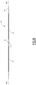
- the electrochemical element 10 or each electrochemical element 10 extends along a median plane PM (see Figure 3 ), which is parallel to the plane of the Figures 1 And 2 and perpendicular to the plane of the Figure 3 .
- the electrochemical element 10 or each electrochemical element 10 comprises a first electrode of a first polarity 22, a first connection member of the first polarity 24, a second electrode of a second polarity 26, and a second connection member of the second polarity 28.
- the electrochemical element 10 is for example of the Lithium-Ion type.
- the first electrode of the first polarity 22 comprises at least one current collector formed of a metal strip for example made of aluminum, coated on at least one face with a mixture containing the active material.
- the first electrode of the first polarity contains an active material which may be a metal oxide comprising lithium atoms, such as lithium cobalt dioxide LCO (LiCoO 2 ), NMC (LiNixMnyCo 1-xy O 2 ), NCA (LiNixCoyAl 1-xy O 2 ), compounds of the type LiMPO 4 where M is selected from the group consisting of Fe, Co, Ni, Mn and a mixture thereof (e.g.
- the first electrode of the first polarity 22 is for example the positive electrode.
- the second electrode of the second polarity 26 comprises at least one current collector formed of a metal strip, for example made of copper, coated on at least one face with a mixture containing the active material.
- the second electrode contains an active material which may be a carbon material capable of inserting lithium atoms, such as graphite or silicon, a lithiated titanium oxide LTO (for example of formula Li 4 Ti 5 O 12 ) or a titanium and niobium oxide TNO (for example of formula TiNb 2 O 7 ).
- the second electrode of the second polarity 26 is for example the negative electrode.
- the electrochemical element 10 comprises a separator, separating the first electrode 22 from the second electrode 26.
- the separator is permeable to lithium ions, but electrically insulating.
- the separator is for example a polyolefin membrane.
- the first electrode of the first polarity 22 and the second electrode of the second polarity 26 extend generally parallel to the median plane PM.
- the electrochemical element 10 also comprises an electrolyte, which may be liquid, such as an organic electrolyte containing lithium salts such as LiPF 6 , solid or gel, such as Polyvinylidene fluoride (PVDF) polymers or a copolymer of Polyvinylidene fluoride and Hexafluoropropylene (PVDF-HFP).
- an electrolyte such as liquid, such as an organic electrolyte containing lithium salts such as LiPF 6 , solid or gel, such as Polyvinylidene fluoride (PVDF) polymers or a copolymer of Polyvinylidene fluoride and Hexafluoropropylene (PVDF-HFP).
- PVDF Polyvinylidene fluoride
- PVDF-HFP Hexafluoropropylene
- the first connection member of the first polarity 24 is electrically connected to the first terminal 14 and the second connection member of the second polarity 28 is electrically connected to the second terminal 16.
- the connection members are adapted to collect the current from the associated electrode.
- the or each first connection member of the first polarity 24 is fixed by welding or brazing to the associated current collector or to the associated electrode.
- the or each second connection member of the second polarity 28 is fixed by welding or brazing to the associated current collector or to the associated electrode.
- the or each first connection member of the first polarity 24 is fixed by ultrasonic welding to the associated current collector or to the associated electrode.
- the or each second connection member of the second polarity 28 is fixed by ultrasonic welding to the associated current collector or to the associated electrode. This is illustrated by the ultrasonic welding zones 110 on the Figure 5 Ultrasonic welding is particularly advantageous because it allows thin sheets to be joined.
- the electrochemical element 10 comprises exactly a single first connection member of the first polarity 24 and a single second connection member of the second polarity 28.
- the connection members of the electrochemical element are constituted by a single first connection member of the first polarity 24 and a single second connection member of the second polarity 28. connection of the first polarity and a single second connection member of the second polarity.
- the electrochemical element 10 or each electrochemical element 10 comprises an envelope 40 provided with a first wall 42 and a second wall 44.
- the envelope 40 is of the “pouch” type, that is to say comprises relatively flexible and easily deformable walls. The walls of the envelope 40 are therefore more easily deformable and less rigid than the walls of the casing 4.
- the electrochemical element 10 is shown in section along line III-III of the Figure 1 .
- the housing 4 is omitted on the Figure 3 .
- the first wall 42 and the second wall 44 each comprise a metal sheet, in particular aluminium, each of which has a thickness EF of between 20 ⁇ m and 150 ⁇ m, in particular between 30 ⁇ m and 60 ⁇ m.
- the thickness EF may advantageously be between 60 ⁇ m and 100 ⁇ m or between 60 ⁇ m and 90 ⁇ m.
- the first wall 42 and the second wall 44 may further comprise a coating, for example made of thermoplastic material, arranged on the metal sheet.
- the walls of the casing are formed from a multilayer film comprising, from the outside to the inside, an electrically insulating and mechanically protective layer, an aluminium sheet and a layer of polypropylene (PP) and/or chemically modified polypropylene (PPa - acid modified polypropylene).
- the walls of the envelope are formed from a multilayer film comprising, from the outside to the inside, a layer of polyethylene terephthalate (PET), a layer of nylon, an aluminum foil and a layer of polypropylene (PP) and/or chemically modified polypropylene (PPa - acid modified polypropylene).
- the envelope 40 comprises two first edges 48, in this case substantially parallel to each other, and two second edges 50, in this case substantially parallel to each other, and in this case substantially perpendicular to the first edges.
- each of the first edges 48 is a long edge and each of the second edges 50 is a short edge.
- the term “short” means that the edge is shorter than each of the long edges and the term “long” means that the edge is longer than each of the short edges.
- the first edges 48 are for example edges opposite each other and the second edges 50 are for example also edges opposite each other.
- the first and/or second edges 48 and 50 may be substantially rectilinear.
- first and/or second edges 48 and 50 are not parallel, and form for example a trapezoid.
- first and/or second edges 48 and 50 are not of different length, but of identical length and therefore form by for example a square or a diamond.
- the envelope 40 comprises at least a first edge and a second non-parallel edge, preferably substantially perpendicular to each other, which together form a corner.
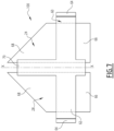
- first and second edges 48 and 50 generally form, when viewed from the front, an enveloping quadrilateral RE, in this case an enveloping rectangle ( Figure 1 ), which is defined by the first and second edges 48 and 50 and by the extension of these edges.
- the edges 48 and 50 coincide with the enveloping quadrilateral.
- the enveloping quadrilateral RE comprises four corners C1, C2, C3, and C4.
- the four corners C1 to C4 are arranged clockwise in the Figures.
- the enveloping quadrilateral RE can also be any quadrilateral, a square, a rhombus or a trapezoid.
- the enveloping quadrilateral RE is replaced by an enveloping geometric shape having at least one corner, for example a semicircle shape.
- the first connection member of the first polarity 24 is arranged in a first corner of the enveloping quadrilateral RE, in this case C1, and the second connection member of the second polarity 28 is also arranged in the first corner of the enveloping quadrilateral, in this case C1.
- the first connection member of the first polarity 24 and the second connection member of the second polarity 28 are therefore arranged in the same corner of the enveloping quadrilateral RE.
- the first connection member of the first polarity 24 and the second connection member of the second polarity 28 are therefore located closer to this corner C1 than to other corners C2 to C4.
- the metal sheet of the first wall 42 and the metal sheet of the second wall 44 are two individual and separate base sheets 52 of metal, each of which has four edges.
- Each of the first edges 48 and the second edges 50 is formed by two edges or edge zones of the two base sheets superimposed and fixed to each other, for example by laser welding or by heat welding. This is shown in FIG. Figure 3
- the envelope 40 therefore comprises four sides formed by a fixing line, in particular a welding line.
- the first connection member of the first polarity 24 is arranged entirely inside the enveloping quadrilateral RE. Furthermore, seen from the front, the second connection member of the second polarity 28 is arranged entirely inside the enveloping quadrilateral RE. the interior of the enveloping quadrilateral RE. In other words, the first and second terminals 24, 28 are arranged entirely within a cylinder having a section of the enveloping quadrilateral RE.
- Each first connection member of the first polarity 24 and/or each second connection member of the second polarity 28 has edges which, when viewed from the front, are set back relative to the latter, i.e. extend completely inside the enveloping quadrilateral RE. This is advantageous, since during the module setting, an undesired contact between the connection members and the casing is avoided. Alternatively, these edges coincide with the enveloping quadrilateral RE.
- the first polarity connecting member 24 is formed by a connecting member tab (referred to as a "tab" in English) which is fixed to a superposition of electrode sheets.
- each second connecting member of the second polarity 28 is formed by a connecting member tab which is fixed to a superposition of electrode sheets.
- Each of the connecting member tabs comprises a metal sheet and optionally a coating.
- the connecting member tab of the first connecting member of the first polarity 24 is for example made of aluminum.
- the connecting member tab of the second connecting member of the second polarity 28 is for example made of copper and optionally coated with nickel.
- Each of the connecting member tabs has a trapezoid shape (see Figure 7 ).
- Each trapezoid comprises two parallel trapezoid bases.
- Each trapezoid comprises a first trapezoid side edge, which is substantially perpendicular to the trapezoid bases.
- Each trapezoid comprises a second trapezoid side edge which is oblique to the trapezoid bases.
- the second trapezoidal lateral edge is parallel to or may coincide with the associated edge 48 or 50 of the casing 40.
- the two second trapezoidal lateral edges of the two adjacent connecting member tabs form an angle of, for example, 90° between them.
- the two trapezoid bases of the two connecting member tabs are parallel to each other.
- the first connection member of the first polarity 24 and the second connection member of the second polarity 28 are arranged side by side.
- the first connection member of the first polarity 24 and the second connection member of the second polarity 28 are arranged in a coplanar manner with respect to each other in the plane median plane PM or in a plane parallel to the median plane PM.
- the first connection member of the first polarity 24 and the second connection member of the second polarity 28 are arranged at a distance from each other along the median plane PM, without overlapping. The distance between the connection members is referenced ET on the Figure 4 .
- the electrochemical element 10 comprises a connecting element 60 which holds the first connection member of the first polarity 24 and the second connection member of the second polarity 28 together in a determined configuration, and which electrically insulates the first connection member of the first polarity 24 from the second connection member of the second polarity 28.
- the connecting element 60 is made of plastic, in particular thermoplastic, such as polypropylene or polyethylene.
- the connecting element 60 is overmolded around the first connection member of the first polarity 24 and the second connection member of the second polarity 28.
- connection assembly 100 which can be handled as a single unit.
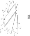
- the connection assembly 100 of the electrochemical element of the Figures 1 to 5 is represented on the Figures 6 to 8 .
- This connection assembly 100 is an assembly according to a first embodiment.
- the connection assembly 100 defines a PMC plane ( Figure 8 ), which in the assembled state of the electrochemical element, coincides with the median plane PM.
- the connection assembly 100 also defines a central axis XX, which extends in the PMC plane and which is an axis of symmetry of the connection assembly 100.
- the connecting element 60 comprises a holding portion 62 which surrounds a circumference of the first connection member of the first polarity 24 and a circumference of the second connection member of the second polarity 28.
- the holding portion 62 is in this case essentially a rectangular profile bar.
- the connecting element 60 is provided with two wings 64, each arranged at one end of the holding portion 62 and having a thickness less than the thickness of the holding portion. In the assembled state of the electrochemical element 10, the wings 64 form connecting joints with the first wall 42 and the second wall 44.
- Each of the first connection member of the first polarity 24 and the second connection member of the second polarity 28 comprises an electrode portion 66 and a terminal portion 68.
- the terminal portion 68 has a substantially triangular shape.
- the electrode portion 66 comprises the first lateral edge of the trapezoid of the connection member tab and the terminal portion 68 comprises the second lateral edge of the trapezoid of the connection member tab.
- the terminal portion 68 is adapted and intended to be electrically connected to the associated terminal 14 or 16 and the electrode portion 66 is adapted and intended to be electrically connected to the associated electrode 22, 26.
- the holding portion 62 defines a boundary between the electrode portion 66 and the terminal portion 68 of each connection member 24, 28.
- the connecting element 60 is advantageously provided with a spacer portion 70, which extends from the holding portion 62 along a trapezoid base of the connecting member tab of the first polarity and along a trapezoid base of the connecting member tab of the second polarity.
- the spacer portion 70 coats the edge of each connecting member tab and extends on either side of the median plane PM.
- the spacer portion 70 has a length less than the length of the associated trapezoid base.
- the spacer portion 70 contributes to electrically insulating the first connecting member of the first polarity 24 and the second connecting member of the second polarity 28 by maintaining the physical distance.
- connection assembly 100 differs from the first embodiment only in the following. Similar elements bear identical references.
- the first connecting member of the first polarity 24 and the second connecting member of the second polarity 28 are not arranged side by side along the median plane PM, but overlap or are juxtaposed.
- first connection member of the first polarity 24 and the second connection member of the second polarity 28 are arranged on either side of the median plane PM, respectively of the plane PMC.
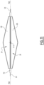
- each of the first connection member of the first polarity 24 and the second connection member of the second polarity 28 has a substantially isosceles triangle shape.
- the apex of the isosceles triangle advantageously coincides with the associated corner C1 or is the point of each connection member closest to this corner C1.
- the terminal portion 68 of the first connection member of the first polarity 24 and the terminal portion 68 of the second connection member of the second polarity 28 have identical shapes and, seen perpendicular to the PMC plane (see Figure 10 ), coincide.
- each of the first connection member of the first polarity 24 and the second connection member of the second polarity 28 has a substantially rectangular shape and a width, measured perpendicular to the axis XX and parallel to the plane PMC, less than half the width of the base of the isosceles triangle of the terminal portion 68.
- the electrode portion 66 of the first connection member of the first polarity 24 and the electrode portion 66 of the second connection member of the second polarity 28 are offset from each other in the PMC plane so as not to overlap (see Figure 10 ).
- the connection of each of the electrode portions 66 to the associated electrode is easy.
- connection assembly 100 differs from the first embodiment only in the following. Similar elements bear identical references.
- the connecting element 60 does not include a spacer portion 70.
- the electrical insulation between the first connection member of the first polarity 24 and the second connection member of the second polarity 28 is therefore ensured mainly by the distance between the two tabs.
- the advantage of this embodiment is to have more flexible tabs to connect several pouches, in particular in the case of thick pouches (total thickness greater than 5 mm).
- connection members in the corners of the cell reduces the inactive area of the electrodes required for connection and maximizes the areas coated by the active material mixture of the electrodes. Grouping two connection members in a corner further increases the active areas of the electrodes. Compared to a conventional design with opposite connection members, a gain of 6.5% in energy can be estimated, for an identical projected surface.
- connection members placed in a corner allows the surface of the connection members to be integrated into the total footprint of the cell and therefore facilitates its integration into a module by providing the possibility of not bending the connection members to connect the cells together.
- bending the connection members for the inter-cell connection is necessary if the cell's footprint is to be minimized. This causes additional handling during assembly of the module as well as weakening of these connection members.
- Another advantage is that integrating the two connection parts in one location reduces the number of heat welds and therefore the potential leak areas. This will consequently increase the reliability of the cell's sealing.
- the electrochemical element 10 comprises a third connection member of the first polarity and a fourth connection member of the second polarity and these connection members are arranged in a corner of the enveloping quadrilateral different from the first corner C1 and in particular in a corner opposite the first corner C1.
- the third connecting member of the first polarity and the fourth connecting member of the second polarity are arranged in corner C3.
- the electrochemical element 10 instead of comprising a connecting element 60 which connects the first connection member of the first polarity 24 and the second connection member of the second polarity 28, comprises two separate connecting elements 60, each of which surrounds only one of the terminals 24, 28, and which are connected via the walls 42, 44.
Landscapes
- Chemical & Material Sciences (AREA)
- Chemical Kinetics & Catalysis (AREA)
- Electrochemistry (AREA)
- General Chemical & Material Sciences (AREA)
- Engineering & Computer Science (AREA)
- Manufacturing & Machinery (AREA)
- Materials Engineering (AREA)
- Connection Of Batteries Or Terminals (AREA)
- Sealing Battery Cases Or Jackets (AREA)
Claims (10)
- Elektrochemische Zelle für eine Batterie des Typs, der Folgendes umfasst- eine erste Elektrode einer ersten Polarität (22),- ein erstes Verbindungsglied der ersten Polarität (24),- eine zweite Elektrode einer zweiten Polarität (26),- ein zweites Verbindungsglied der zweiten Polarität (28),- eine Hülle (40), umfassend eine erste Wand (42) und eine zweite Wand (44),- die Hülle umfassend mindestens einen ersten Rand (48) und mindestens einen zweiten Rand (50),wobei der/die erste(n) und zweite(n) Rand/Ränder eine umhüllende geometrische Form (RE) bilden, die mindestens eine Ecke (C1) aufweist,dadurch gekennzeichnet, dassdas erste Verbindungsglied der ersten Polarität (24) und das zweite Verbindungsglied der zweiten Polarität (28) vollständig innerhalb der umhüllenden geometrischen Form (RE) angeordnet sind, dadurch, dassdas erste Verbindungsglied der ersten Polarität in einer ersten Ecke (C1) der umhüllenden geometrischen Form angeordnet ist, unddas zweite Verbindungsglied der zweiten Polarität auch in der ersten Ecke (C1) der umhüllenden geometrischen Form angeordnet ist.
- Elektrochemisches Element nach Anspruch 1, wobei die umhüllende geometrische Form (RE) ein umhüllendes Viereck ist, insbesondere ein Rechteck oder ein Trapez.
- Elektrochemisches Element nach Anspruch 1 oder 2, wobei ausschließlich in einer einzigen Ecke (C1) der umhüllenden geometrischen Form (RE) ein Verbindungsglied der ersten Polarität (24) angeordnet ist und ein Verbindungsglied der zweiten Polarität (28) angeordnet ist und in keiner weiteren Ecke, die gegebenenfalls vorhanden ist, der umhüllenden geometrischen Form (RE) ein Verbindungsglied des elektrochemischen Elements angeordnet ist.
- Elektrochemisches Element nach einem der vorherigen Ansprüche, wobei das erste Verbindungsglied der ersten Polarität (24) und das zweite Verbindungsglied der zweiten Polarität (28) Seite an Seite angeordnet sind oder wobei
das erste Verbindungsglied der ersten Polarität (24) und das zweite Verbindungsglied der zweiten Polarität (28) nebeneinander angeordnet sind. - Elektrochemisches Element nach einem der vorherigen Ansprüche, wobei das erste Verbindungsglied der ersten Polarität einen Anschlussabschnitt (68) umfasst und/oder wobei das zweite Verbindungsglied der zweiten Polarität einen Anschlussabschnitt (68) umfasst, wobei jeder Anschlussabschnitt (68) angepasst ist, um elektrisch mit einem assoziierten Anschluss (14, 16) verbunden zu werden, und wobei jeder Anschlussabschnitt eine im Wesentlichen dreieckige Form aufweist.
- Elektrochemisches Element nach einem der vorherigen Ansprüche, wobei das elektrochemische Element (10) ein Verbindungselement (60) aus Kunststoff umfasst, das das erste Verbindungsglied der ersten Polarität und das zweite Verbindungsglied der zweiten Polarität in einer bestimmten Konfiguration zusammenhält und das erste Verbindungsglied der ersten Polarität (24) von dem zweiten Verbindungsglied der zweiten Polarität (28) elektrisch isoliert.
- Elektrochemisches Element nach Anspruch 6, wobei das Verbindungselement (60) um das erste Verbindungsglied der ersten Polarität (24) und das zweite Verbindungsglied der zweiten Polarität (28) herum geformt ist.
- Elektrochemisches Element nach einem der vorherigen Ansprüche, wobei das erste Verbindungsglied der ersten Polarität (24) und/oder das zweite Verbindungsglied der zweiten Polarität (28) an ihrer jeweiligen Elektrode insbesondere durch Ultraschallschweißen befestigt ist bzw. sind.
- Elektrochemisches Element nach einem der vorherigen Ansprüche, wobei die erste Wand (42) und die zweite Wand (44) jeweils eine Metallbasisfolie umfassen und wobei die Metallbasisfolien jeweils eine Stärke (EF) zwischen 20 µm und 150 µm, insbesondere entweder zwischen 30 µm und 60 µm oder zwischen 60 µm und 100 µm oder zwischen 60 µm und 90 µm, aufweisen.
- Batterie, insbesondere Lithium-Ionen-Batterie, umfassend ein Gehäuse und mindestens ein elektrochemischen Element, die Batterie vorzugsweise umfassend einen ersten Anschluss (14) und einen zweiten Anschluss (16), dadurch gekennzeichnet, dass das mindestens eine elektrochemische Element (10) ein Element nach einem der vorherigen Ansprüche ist, und dass vorzugsweise das erste Verbindungsglied der ersten Polarität (24) elektrisch mit dem ersten Anschluss (14) verbunden ist und das zweite Verbindungsglied der zweiten Polarität (28) elektrisch mit dem zweiten Anschluss (16) verbunden ist.
Applications Claiming Priority (2)
| Application Number | Priority Date | Filing Date | Title |
|---|---|---|---|
| FR2105171A FR3123159B1 (fr) | 2021-05-18 | 2021-05-18 | Elément électrochimique pour batterie, et batterie correspondante |
| PCT/EP2022/063189 WO2022243243A1 (fr) | 2021-05-18 | 2022-05-16 | Elément électrochimique pour batterie, et batterie correspondante |
Publications (2)
| Publication Number | Publication Date |
|---|---|
| EP4342018A1 EP4342018A1 (de) | 2024-03-27 |
| EP4342018B1 true EP4342018B1 (de) | 2025-01-29 |
Family
ID=77180125
Family Applications (1)
| Application Number | Title | Priority Date | Filing Date |
|---|---|---|---|
| EP22729544.1A Active EP4342018B1 (de) | 2021-05-18 | 2022-05-16 | Elektrochemisches element für eine batterie und entsprechende batterie |
Country Status (4)
| Country | Link |
|---|---|
| US (1) | US20240234829A1 (de) |
| EP (1) | EP4342018B1 (de) |
| FR (1) | FR3123159B1 (de) |
| WO (1) | WO2022243243A1 (de) |
Families Citing this family (1)
| Publication number | Priority date | Publication date | Assignee | Title |
|---|---|---|---|---|
| FR3159705B1 (fr) | 2024-02-28 | 2026-01-02 | Stellantis Auto Sas | Element electrochimique de stockage d’energie et batterie de puissance comportant des elements de liaison electrique |
Family Cites Families (11)
| Publication number | Priority date | Publication date | Assignee | Title |
|---|---|---|---|---|
| GB2245412B (en) | 1990-06-20 | 1995-01-25 | Dowty Electronic Components | Battery comprising interconnecting means of electrochemical cell units |
| US5419982A (en) * | 1993-12-06 | 1995-05-30 | Valence Technology, Inc. | Corner tab termination for flat-cell batteries |
| SE519958C2 (sv) | 2001-09-20 | 2003-04-29 | Nilar Europ Ab | Ett bipolärt batteri och en biplåtsammansättning |
| US7244527B2 (en) | 2003-10-16 | 2007-07-17 | Electro Energy, Inc. | Multi-cell battery charge control |
| US8614017B2 (en) | 2010-10-27 | 2013-12-24 | Medtronic, Inc. | Electrochemical cell with electrode elements that include alignment aperatures |
| US9142840B2 (en) | 2011-10-21 | 2015-09-22 | Blackberry Limited | Method of reducing tabbing volume required for external connections |
| CN202373667U (zh) | 2011-12-21 | 2012-08-08 | 东莞新能源科技有限公司 | 锂离子电池的电芯及其极片 |
| KR102211525B1 (ko) | 2014-06-17 | 2021-02-02 | 삼성에스디아이 주식회사 | 코너 폴딩부를 갖는 이차 전지 |
| KR20160041402A (ko) | 2014-10-07 | 2016-04-18 | 주식회사 엘지화학 | 파우치형 이차 전지 및 그의 제조방법 |
| WO2016205663A1 (en) | 2015-06-18 | 2016-12-22 | 24M Technologies, Inc. | Single pouch battery cells and methods of manufacture |
| CN108400385A (zh) | 2018-01-17 | 2018-08-14 | 柔电(武汉)科技有限公司 | 使用活性自支撑极片制备高能量密度软包锂电池的方法 |
-
2021
- 2021-05-18 FR FR2105171A patent/FR3123159B1/fr active Active
-
2022
- 2022-05-16 EP EP22729544.1A patent/EP4342018B1/de active Active
- 2022-05-16 WO PCT/EP2022/063189 patent/WO2022243243A1/fr not_active Ceased
- 2022-05-16 US US18/562,098 patent/US20240234829A1/en active Pending
Also Published As
| Publication number | Publication date |
|---|---|
| FR3123159B1 (fr) | 2023-04-28 |
| WO2022243243A1 (fr) | 2022-11-24 |
| FR3123159A1 (fr) | 2022-11-25 |
| US20240234829A1 (en) | 2024-07-11 |
| EP4342018A1 (de) | 2024-03-27 |
Similar Documents
| Publication | Publication Date | Title |
|---|---|---|
| EP2583332B1 (de) | Stromabnehmer mit integrierter dichtung sowie zweipolige batterie mit einem derartigen stromabnehmer | |
| EP2073300B1 (de) | Bipolare Batterie mit verbesserter Abdichtung zwischen den Platten | |
| EP2870655B1 (de) | Stromabnehmer mit integrierter dichtungsvorrichtung, bipolare batterie mit solch einem stromabnehmer | |
| EP2904654B1 (de) | Bipolare batterie mit einem stromkollektor mit eingebauter dichtung und verfahren zur herstellung solch einer batterie | |
| WO2014167504A1 (fr) | Accumulateur électrochimique au lithium avec boîtier a dissipation thermique améliorée, pack-batterie et procédés de réalisation associés | |
| FR3011128A1 (fr) | Procede de realisation d'un faisceau electrochimique d'un accumulateur au lithium | |
| FR3034571A1 (fr) | Dispositif electrochimique, tel qu’une microbatterie ou un systeme electrochrome, recouvert par une couche d’encapsulation comprenant un film barriere et un film adhesif, et procede de realisation d’un tel dispositif. | |
| EP4154348B1 (de) | Elektrochemische zelle und batterie dafür | |
| EP4342018B1 (de) | Elektrochemisches element für eine batterie und entsprechende batterie | |
| EP3095147B1 (de) | Elektrochemischer akkumulator mit gehäuse und terminal bestehend aus einer aluminiumlegierung | |
| CH716259A2 (fr) | Batterie cellulaire. | |
| EP3114726B1 (de) | Anordnungsmodul mit elektrochemischen, von laschen und verbindungsclips aufgenommenen zellen | |
| EP3482432B1 (de) | Metall-ion akkumulator mit hohe kapazität, wessen flexibilität für eine hohe gleichförmichkeit dient | |
| EP2826082B1 (de) | Leichtgewichtiger elektrochemischer speicher auf li-ionen-basis | |
| FR3109026A1 (fr) | Elément électrochimique pour batterie et batterie correspondante | |
| EP4454047A1 (de) | Elektrochemisches bündel, batterieelement und zugehörige herstellungsverfahren | |
| EP3327819B1 (de) | Metallionen-akkumulator mit einem stapel elektroden, gekennzeichnet durch eine hohe energiedichte und eine hohe kapazität | |
| WO2025052072A1 (fr) | Procédé de fabrication d'une cellule de batterie cylindrique | |
| EP4604233A1 (de) | Zellengehäuseschaufel, gehäuse dafür, batteriezelle mit solch einer gehäuseschale und anordnung solcher zellen | |
| EP4604248A1 (de) | Zellgehäuseabdeckung, gehäuse dafür, batteriezelle mit solch einer abdeckung und anordnung solcher zellen | |
| FR3156597A1 (fr) | Module de batterie ou pack-batterie, comprenant une matrice à accumulateurs de format cylindrique articulés entre eux par bielle(s) à axe(s) d’articulation formé(s) par les boitiers des accumulateurs et à busbars réalisant des connexions électriques dans certaines positions articulées. | |
| FR3156596A1 (fr) | Module de batterie ou pack-batterie, comprenant une matrice à accumulateurs de format cylindrique articulés entre eux par bielle(s) à axe(s) d’articulation formé(s) par les boitiers des accumulateurs. | |
| WO2025068359A1 (fr) | Ensemble comprenant un élément électrochimique et un élément électrique rechargeable et procédé de fabrication associé | |
| EP4154344A1 (de) | Elektrochemische anordnung, zugehörige batterie und verfahren |
Legal Events
| Date | Code | Title | Description |
|---|---|---|---|
| STAA | Information on the status of an ep patent application or granted ep patent |
Free format text: STATUS: UNKNOWN |
|
| STAA | Information on the status of an ep patent application or granted ep patent |
Free format text: STATUS: THE INTERNATIONAL PUBLICATION HAS BEEN MADE |
|
| PUAI | Public reference made under article 153(3) epc to a published international application that has entered the european phase |
Free format text: ORIGINAL CODE: 0009012 |
|
| STAA | Information on the status of an ep patent application or granted ep patent |
Free format text: STATUS: REQUEST FOR EXAMINATION WAS MADE |
|
| 17P | Request for examination filed |
Effective date: 20231116 |
|
| AK | Designated contracting states |
Kind code of ref document: A1 Designated state(s): AL AT BE BG CH CY CZ DE DK EE ES FI FR GB GR HR HU IE IS IT LI LT LU LV MC MK MT NL NO PL PT RO RS SE SI SK SM TR |
|
| DAV | Request for validation of the european patent (deleted) | ||
| DAX | Request for extension of the european patent (deleted) | ||
| GRAP | Despatch of communication of intention to grant a patent |
Free format text: ORIGINAL CODE: EPIDOSNIGR1 |
|
| STAA | Information on the status of an ep patent application or granted ep patent |
Free format text: STATUS: GRANT OF PATENT IS INTENDED |
|
| INTG | Intention to grant announced |
Effective date: 20240925 |
|
| GRAS | Grant fee paid |
Free format text: ORIGINAL CODE: EPIDOSNIGR3 |
|
| GRAA | (expected) grant |
Free format text: ORIGINAL CODE: 0009210 |
|
| STAA | Information on the status of an ep patent application or granted ep patent |
Free format text: STATUS: THE PATENT HAS BEEN GRANTED |
|
| AK | Designated contracting states |
Kind code of ref document: B1 Designated state(s): AL AT BE BG CH CY CZ DE DK EE ES FI FR GB GR HR HU IE IS IT LI LT LU LV MC MK MT NL NO PL PT RO RS SE SI SK SM TR |
|
| REG | Reference to a national code |
Ref country code: GB Ref legal event code: FG4D Free format text: NOT ENGLISH |
|
| REG | Reference to a national code |
Ref country code: CH Ref legal event code: EP |
|
| REG | Reference to a national code |
Ref country code: DE Ref legal event code: R096 Ref document number: 602022010228 Country of ref document: DE |
|
| REG | Reference to a national code |
Ref country code: IE Ref legal event code: FG4D Free format text: LANGUAGE OF EP DOCUMENT: FRENCH |
|
| REG | Reference to a national code |
Ref country code: NL Ref legal event code: MP Effective date: 20250129 |
|
| PG25 | Lapsed in a contracting state [announced via postgrant information from national office to epo] |
Ref country code: NL Free format text: LAPSE BECAUSE OF FAILURE TO SUBMIT A TRANSLATION OF THE DESCRIPTION OR TO PAY THE FEE WITHIN THE PRESCRIBED TIME-LIMIT Effective date: 20250129 |
|
| PG25 | Lapsed in a contracting state [announced via postgrant information from national office to epo] |
Ref country code: RS Free format text: LAPSE BECAUSE OF FAILURE TO SUBMIT A TRANSLATION OF THE DESCRIPTION OR TO PAY THE FEE WITHIN THE PRESCRIBED TIME-LIMIT Effective date: 20250429 |
|
| PG25 | Lapsed in a contracting state [announced via postgrant information from national office to epo] |
Ref country code: FI Free format text: LAPSE BECAUSE OF FAILURE TO SUBMIT A TRANSLATION OF THE DESCRIPTION OR TO PAY THE FEE WITHIN THE PRESCRIBED TIME-LIMIT Effective date: 20250129 |
|
| PG25 | Lapsed in a contracting state [announced via postgrant information from national office to epo] |
Ref country code: PL Free format text: LAPSE BECAUSE OF FAILURE TO SUBMIT A TRANSLATION OF THE DESCRIPTION OR TO PAY THE FEE WITHIN THE PRESCRIBED TIME-LIMIT Effective date: 20250129 |
|
| PGFP | Annual fee paid to national office [announced via postgrant information from national office to epo] |
Ref country code: DE Payment date: 20250513 Year of fee payment: 4 |
|
| PG25 | Lapsed in a contracting state [announced via postgrant information from national office to epo] |
Ref country code: ES Free format text: LAPSE BECAUSE OF FAILURE TO SUBMIT A TRANSLATION OF THE DESCRIPTION OR TO PAY THE FEE WITHIN THE PRESCRIBED TIME-LIMIT Effective date: 20250129 |
|
| REG | Reference to a national code |
Ref country code: LT Ref legal event code: MG9D |
|
| PG25 | Lapsed in a contracting state [announced via postgrant information from national office to epo] |
Ref country code: IS Free format text: LAPSE BECAUSE OF FAILURE TO SUBMIT A TRANSLATION OF THE DESCRIPTION OR TO PAY THE FEE WITHIN THE PRESCRIBED TIME-LIMIT Effective date: 20250529 Ref country code: NO Free format text: LAPSE BECAUSE OF FAILURE TO SUBMIT A TRANSLATION OF THE DESCRIPTION OR TO PAY THE FEE WITHIN THE PRESCRIBED TIME-LIMIT Effective date: 20250429 |
|
| REG | Reference to a national code |
Ref country code: AT Ref legal event code: MK05 Ref document number: 1764397 Country of ref document: AT Kind code of ref document: T Effective date: 20250129 |
|
| PG25 | Lapsed in a contracting state [announced via postgrant information from national office to epo] |
Ref country code: HR Free format text: LAPSE BECAUSE OF FAILURE TO SUBMIT A TRANSLATION OF THE DESCRIPTION OR TO PAY THE FEE WITHIN THE PRESCRIBED TIME-LIMIT Effective date: 20250129 |
|
| PG25 | Lapsed in a contracting state [announced via postgrant information from national office to epo] |
Ref country code: PT Free format text: LAPSE BECAUSE OF FAILURE TO SUBMIT A TRANSLATION OF THE DESCRIPTION OR TO PAY THE FEE WITHIN THE PRESCRIBED TIME-LIMIT Effective date: 20250529 Ref country code: LV Free format text: LAPSE BECAUSE OF FAILURE TO SUBMIT A TRANSLATION OF THE DESCRIPTION OR TO PAY THE FEE WITHIN THE PRESCRIBED TIME-LIMIT Effective date: 20250129 |
|
| PGFP | Annual fee paid to national office [announced via postgrant information from national office to epo] |
Ref country code: FR Payment date: 20250410 Year of fee payment: 4 |
|
| PG25 | Lapsed in a contracting state [announced via postgrant information from national office to epo] |
Ref country code: BG Free format text: LAPSE BECAUSE OF FAILURE TO SUBMIT A TRANSLATION OF THE DESCRIPTION OR TO PAY THE FEE WITHIN THE PRESCRIBED TIME-LIMIT Effective date: 20250129 Ref country code: GR Free format text: LAPSE BECAUSE OF FAILURE TO SUBMIT A TRANSLATION OF THE DESCRIPTION OR TO PAY THE FEE WITHIN THE PRESCRIBED TIME-LIMIT Effective date: 20250430 |
|
| PG25 | Lapsed in a contracting state [announced via postgrant information from national office to epo] |
Ref country code: AT Free format text: LAPSE BECAUSE OF FAILURE TO SUBMIT A TRANSLATION OF THE DESCRIPTION OR TO PAY THE FEE WITHIN THE PRESCRIBED TIME-LIMIT Effective date: 20250129 |
|
| PG25 | Lapsed in a contracting state [announced via postgrant information from national office to epo] |
Ref country code: SE Free format text: LAPSE BECAUSE OF FAILURE TO SUBMIT A TRANSLATION OF THE DESCRIPTION OR TO PAY THE FEE WITHIN THE PRESCRIBED TIME-LIMIT Effective date: 20250129 |
|
| PG25 | Lapsed in a contracting state [announced via postgrant information from national office to epo] |
Ref country code: SM Free format text: LAPSE BECAUSE OF FAILURE TO SUBMIT A TRANSLATION OF THE DESCRIPTION OR TO PAY THE FEE WITHIN THE PRESCRIBED TIME-LIMIT Effective date: 20250129 |
|
| PG25 | Lapsed in a contracting state [announced via postgrant information from national office to epo] |
Ref country code: DK Free format text: LAPSE BECAUSE OF FAILURE TO SUBMIT A TRANSLATION OF THE DESCRIPTION OR TO PAY THE FEE WITHIN THE PRESCRIBED TIME-LIMIT Effective date: 20250129 |
|
| PG25 | Lapsed in a contracting state [announced via postgrant information from national office to epo] |
Ref country code: IT Free format text: LAPSE BECAUSE OF FAILURE TO SUBMIT A TRANSLATION OF THE DESCRIPTION OR TO PAY THE FEE WITHIN THE PRESCRIBED TIME-LIMIT Effective date: 20250129 |
|
| PG25 | Lapsed in a contracting state [announced via postgrant information from national office to epo] |
Ref country code: EE Free format text: LAPSE BECAUSE OF FAILURE TO SUBMIT A TRANSLATION OF THE DESCRIPTION OR TO PAY THE FEE WITHIN THE PRESCRIBED TIME-LIMIT Effective date: 20250129 Ref country code: CZ Free format text: LAPSE BECAUSE OF FAILURE TO SUBMIT A TRANSLATION OF THE DESCRIPTION OR TO PAY THE FEE WITHIN THE PRESCRIBED TIME-LIMIT Effective date: 20250129 |
|
| PG25 | Lapsed in a contracting state [announced via postgrant information from national office to epo] |
Ref country code: RO Free format text: LAPSE BECAUSE OF FAILURE TO SUBMIT A TRANSLATION OF THE DESCRIPTION OR TO PAY THE FEE WITHIN THE PRESCRIBED TIME-LIMIT Effective date: 20250129 |
|
| PG25 | Lapsed in a contracting state [announced via postgrant information from national office to epo] |
Ref country code: SK Free format text: LAPSE BECAUSE OF FAILURE TO SUBMIT A TRANSLATION OF THE DESCRIPTION OR TO PAY THE FEE WITHIN THE PRESCRIBED TIME-LIMIT Effective date: 20250129 |
|
| REG | Reference to a national code |
Ref country code: DE Ref legal event code: R097 Ref document number: 602022010228 Country of ref document: DE |
|
| P01 | Opt-out of the competence of the unified patent court (upc) registered |
Free format text: CASE NUMBER: UPC_APP_8020_4342018/2025 Effective date: 20250926 |
|
| PLBE | No opposition filed within time limit |
Free format text: ORIGINAL CODE: 0009261 |
|
| STAA | Information on the status of an ep patent application or granted ep patent |
Free format text: STATUS: NO OPPOSITION FILED WITHIN TIME LIMIT |
|
| REG | Reference to a national code |
Ref country code: CH Ref legal event code: L10 Free format text: ST27 STATUS EVENT CODE: U-0-0-L10-L00 (AS PROVIDED BY THE NATIONAL OFFICE) Effective date: 20251210 |
|
| REG | Reference to a national code |
Ref country code: CH Ref legal event code: H13 Free format text: ST27 STATUS EVENT CODE: U-0-0-H10-H13 (AS PROVIDED BY THE NATIONAL OFFICE) Effective date: 20251223 |
|
| 26N | No opposition filed |
Effective date: 20251030 |
|
| PG25 | Lapsed in a contracting state [announced via postgrant information from national office to epo] |
Ref country code: LU Free format text: LAPSE BECAUSE OF NON-PAYMENT OF DUE FEES Effective date: 20250516 |
|
| PG25 | Lapsed in a contracting state [announced via postgrant information from national office to epo] |
Ref country code: CH Free format text: LAPSE BECAUSE OF NON-PAYMENT OF DUE FEES Effective date: 20250531 |
|
| PG25 | Lapsed in a contracting state [announced via postgrant information from national office to epo] |
Ref country code: MC Free format text: LAPSE BECAUSE OF FAILURE TO SUBMIT A TRANSLATION OF THE DESCRIPTION OR TO PAY THE FEE WITHIN THE PRESCRIBED TIME-LIMIT Effective date: 20250129 |