EP4340211A1 - Power conversion device - Google Patents
Power conversion device Download PDFInfo
- Publication number
- EP4340211A1 EP4340211A1 EP22807014.0A EP22807014A EP4340211A1 EP 4340211 A1 EP4340211 A1 EP 4340211A1 EP 22807014 A EP22807014 A EP 22807014A EP 4340211 A1 EP4340211 A1 EP 4340211A1
- Authority
- EP
- European Patent Office
- Prior art keywords
- power
- calculating
- phase error
- frequency
- value
- Prior art date
- Legal status (The legal status is an assumption and is not a legal conclusion. Google has not performed a legal analysis and makes no representation as to the accuracy of the status listed.)
- Granted
Links
Images





Classifications
-
- H—ELECTRICITY
- H02—GENERATION; CONVERSION OR DISTRIBUTION OF ELECTRIC POWER
- H02P—CONTROL OR REGULATION OF ELECTRIC MOTORS, ELECTRIC GENERATORS OR DYNAMO-ELECTRIC CONVERTERS; CONTROLLING TRANSFORMERS, REACTORS OR CHOKE COILS
- H02P21/00—Arrangements or methods for the control of electric machines by vector control, e.g. by control of field orientation
- H02P21/14—Estimation or adaptation of machine parameters, e.g. flux, current or voltage
- H02P21/18—Estimation of position or speed
-
- H—ELECTRICITY
- H02—GENERATION; CONVERSION OR DISTRIBUTION OF ELECTRIC POWER
- H02P—CONTROL OR REGULATION OF ELECTRIC MOTORS, ELECTRIC GENERATORS OR DYNAMO-ELECTRIC CONVERTERS; CONTROLLING TRANSFORMERS, REACTORS OR CHOKE COILS
- H02P21/00—Arrangements or methods for the control of electric machines by vector control, e.g. by control of field orientation
- H02P21/22—Current control, e.g. using a current control loop
-
- H—ELECTRICITY
- H02—GENERATION; CONVERSION OR DISTRIBUTION OF ELECTRIC POWER
- H02P—CONTROL OR REGULATION OF ELECTRIC MOTORS, ELECTRIC GENERATORS OR DYNAMO-ELECTRIC CONVERTERS; CONTROLLING TRANSFORMERS, REACTORS OR CHOKE COILS
- H02P21/00—Arrangements or methods for the control of electric machines by vector control, e.g. by control of field orientation
- H02P21/24—Vector control not involving the use of rotor position or rotor speed sensors
-
- H—ELECTRICITY
- H02—GENERATION; CONVERSION OR DISTRIBUTION OF ELECTRIC POWER
- H02P—CONTROL OR REGULATION OF ELECTRIC MOTORS, ELECTRIC GENERATORS OR DYNAMO-ELECTRIC CONVERTERS; CONTROLLING TRANSFORMERS, REACTORS OR CHOKE COILS
- H02P27/00—Arrangements or methods for the control of AC motors characterised by the kind of supply voltage
- H02P27/04—Arrangements or methods for the control of AC motors characterised by the kind of supply voltage using variable-frequency supply voltage, e.g. inverter or converter supply voltage
- H02P27/06—Arrangements or methods for the control of AC motors characterised by the kind of supply voltage using variable-frequency supply voltage, e.g. inverter or converter supply voltage using DC to AC converters or inverters
Definitions
- This invention relates to power conversion devices.
- Patent Documents 1 Japanese Unexamined Patent Publication No. 2006-197712
- the technology described in the literature 1 calculates two kinds of reactive power (Q and Q hat) and calculates frequency estimates of the inverter to set the deviation ⁇ Q to zero. This allows the frequency estimates to be less sensitive to temperature changes in the magnet motor winding resistance, resulting in highly accurate control characteristics.
- the first motor frequency is estimated so that the deviation ⁇ Q is zero by calculating two types of reactive power using the technology of Patent Document 1.
- the medium to high speed range for example, another technique is used to estimate the phase error (phase of control and magnet motor) using the extended induced voltage, and the second motor frequency is estimated by PI control to follow the zero.
- the purpose of this invention is to provide a power conversion device with stable and accurate control characteristics that can prevent torque shock when the motor frequency changes and does not require adjustment of electrical circuit parameters.
- Present invention is a power conversion device comprising a power converter outputting signals to the motor to vary the output frequency, output voltage and output current of the motor, a control unit controlling the power converter wherein the control unit is calculating the first power from the output voltage and the output current, calculating the second power from the output current, electrical circuit parameters and a frequency estimates, calculating the first phase error estimate in a first frequency domain so that the first power follows the second power, calculating the second phase error estimate in a second frequency domain different from the first frequency domain, controlling the frequency estimates so that the first phase error estimate or the second phase error estimate follows the command value of the phase error estimate.
- the invention can prevent torque shock when the motor frequency changes, as well as provide stable and highly accurate control characteristics without the need to adjust electrical circuit parameters.
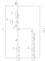
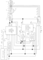
- Fig. 1 shows the system configuration with power conversion device and magnet motor in example 1.
- the power conversion device in this example achieves stable and highly accurate control characteristics even in the low-speed range, which is about 10% of the base frequency from standstill, in position sensor-less control that omits encoders and other devices that detect the magnet motor's magnet phase.
- Magnet motor 1 outputs motor torque that is a composite of the torque component due to the magnetic flux of the permanent magnet and the torque component due to the inductance of the armature winding.
- Power converter 2 is equipped with semiconductor devices as switching elements. Power converter 2 inputs 3-phase ac voltage command values v u *, v v * and v w * and outputs voltage values proportional to 3-phase ac voltage command values v u *, v v * and v w *. Based on the output of power converter 2, magnet motorl is driven and the output voltage value, output frequency value and output current of magnet motorl are controlled variably. Insulated gate bipolar transistor (IGBT) may be used as switching element.
- IGBT Insulated gate bipolar transistor
- DC power supply 3 supplies DC voltage and DC current to power converter 2.
- the current detector 4 outputs i uc , i vc and i wc , which are the detected three phases AC currents i u , i v and i w of the magnet motor 1.
- the current detector 4 also detects the three phases AC currents of two of the magnet motorl, e.g., phase u and phase w.
- the current detector 4 is shown in the power conversion device, but it can also be located outside the power conversion device.
- the control unit includes coordinate conversion unit 5, speed control arithmetic unit 6, vector control arithmetic unit 7, phase error estimation in the medium and high-speed range 8, phase error estimation unit in the low-speed range .9, frequency and phase estimation unit10, and coordinate conversion unit11.
- the control unit controls the output of power converter 2 so that the output voltage value, output frequency value and output current of magnet motorl are controlled variably.
- the control section is composed of semiconductor integrated circuits (arithmetic and control means) such as microcomputer and digital signal processor (DSP). Any or all of the control section can be implemented by hardware such as an ASIC (Application Specific Integrated Circuit) or FPGA (Field Programmable Gate Array).
- the CPU Central Processing Unit
- the control section reads a program held in a memory or other recording device and executes the processing of each part such as the coordinate conversion unit 5 described above.
- Coordinate conversion unit 5 outputs d-axis and q-axis current detection values i dc and i qc from the detected values i uc , i vc , and i wc of the three phase AC currents i u , i v , and i w and the phase estimate ⁇ dc .
- the speed control arithmetic unit 6 calculates the torque command value ⁇ * based on the frequency command value ⁇ r * and frequency estimates ⁇ dc , and outputs the q-axis current command value i q * by dividing by the torque factor.
- the frequency command value ⁇ r * is used to determine the medium to high speed range and low speed range, and frequency estimates ⁇ dc corresponds to the motor speed estimate (motor rotation speed estimate).
- Vector control arithmetic unit 7 outputs d-axis and q-axis current command values i d *, i q *, current detection values i dc , i qc , frequency estimates ⁇ dc and d-axis and q-axis voltage calculated based on the electrical circuit parameters of magnet motorl command value v dc ** and v qc ** are output.
- the phase error estimation in the medium and high-speed range 8 uses the voltage command values v dc **, v qc **, frequency estimates ⁇ dc , current detection values i dc , i qc and electrical circuit parameters of magnet motor 1 for the d c and q c axes, which are control axes.
- the estimated value ⁇ c_H of phase error ⁇ which is the deviation between the phase ⁇ dc of control in the medium and high speed range and the phase ⁇ d of the magnet motor 1 is output.
- the phase error estimation unit in the low-speed range 9 uses the voltage command values v dc **, v qc ** , frequency estimates ⁇ dc , current detection values i dc , i qc and electrical circuit parameters of magnet motor1 for the d c and q c axes, which are control axes.
- the estimated value ⁇ c_L of the phase error ⁇ which is the deviation between the phase ⁇ dc of the control and the phase ⁇ d of the magnet motorl in the low speed range, is calculated.
- the frequency and phase estimation unit 10 is based on the phase error estimates at low speeds ⁇ c_L or the estimated phase error in the medium and high speed range ⁇ c_H , frequency estimates ⁇ dc and phase estimates ⁇ dc are output.
- the coordinate conversion unit 11 outputs the voltage command values v u *, v v * and v w * for 3-phase AC from the voltage command values v dc ** and v qc ** for the d c and q c axes and the phase estimate value ⁇ dc .
- the speed control arithmetic unit 6 calculates the torque command ⁇ * and the q-axis current command i q * according to (Formula 1) using proportional control and integral control so that the frequency estimates ⁇ dc follow the frequency command value ⁇ r *.
- K sp proportional gain of speed control
- K si integral gain of speed control
- P m pole logarithm
- K e induced voltage coefficient
- L d d-axis inductance
- L q q-axis inductance
- * set value
- s Laplace operator
- the vector control arithmetic unit 7 firstly uses the electrical circuit parameters of the permanent magnet motor 1: the set value of winding resistance R*, the set value of d-axis inductance L d *, the set value of q-axis inductance L q *, the value of induced voltage coefficient K e *, the current command values i d * and i q * for the d c axes and q c axes and frequency estimates ⁇ dc to output the voltage reference values v dc * and v qc * for the d c and q c axes according to (Formula 2).
- vector control arithmetic unit 7 calculates the voltage correction values ⁇ v dc and ⁇ v qc for the d c and q c axes according to (Formula 3) using proportional and integral control so that the current detection values i dc and i qc for each component follow the current command values i d * and i q * for the d c and q c axes.
- vector control arithmetic unit 7 calculates the voltage command values v dc ** and v qc ** for the d c and q c axes according to (Formula 4).
- v dc * * v dc * + ⁇ v dc
- v qc * * v qc * + ⁇ v qc
- Fig. 2 shows the block of phase error estimation in the medium and high-speed range 8.
- Phase error estimation in the medium and high-speed range 8 is based on the voltage command values v dc **, v qc ** of dc axis and qc and current detection values i dc and i qc and the electrical circuit parameters of magnet motor 1 (R* and L q *), the calculation section 81 of the phase error estimates in the medium and high-speed range using the extended induced voltage method calculates the phase error estimates ⁇ c_H in the medium and high-speed range according to (Formula 5).
- ⁇ c _ H tan ⁇ 1 v dc * * ⁇ R * i dc + ⁇ dc L q * i qc v qc * * ⁇ R * i qc ⁇ dc L q * i dc
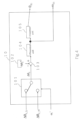
- FIG. 3 shows the blocks of the phase error estimation unit in the low-speed range 9.
- the phase error estimation unit in the low-speed ranges calculates the first reactive power Q qc ** in the first reactive power calculation unit91 using the voltage command values v dc ** of the d c axis and v of the q c axis as the output voltage of magnet motorl and the voltage command values v of the q axis as the output current of magnet motorl
- the first reactive power Q c is calculated according to (Formula 6) using the current detection values i dc of the d c axis and i qc of the q c axis as the output current of magnet motorl.
- Q c v dc * * i qc ⁇ v qc * * i dc
- the second reactive power calculation section 92 calculates the second reactive power Q c ⁇ using the current detection values i dc of the d c axis and the current detection values i qc of the q c axis, frequency estimates ⁇ dc and the electrical circuit parameters of magnet motorl (L d * , L q * and K e * ) according to (Formula 7) .
- Q c ⁇ ⁇ ⁇ dc L d * i dc 2 + L q * i qc 2 ⁇ ⁇ dc K e * i dc
- the first reactive power Q c and second reactive power Q c ⁇ are input to the subtraction section 93, and the deviation, ⁇ Q c , is calculated.
- the deviation of reactive power, ⁇ Q c is input to PI control calculation section 95 (hereinafter referred to as PI control section) to follow the command value of reactive power deviation 94 which is "0.”
- the PI control section 95 calculates the estimated-value of phase error ⁇ c_L of the phase error ⁇ in the low speed range according to (Formula 8) using P (proportional) + I (integral) control calculation.
- ⁇ c _ L K p ⁇ + K i ⁇ s 0 ⁇ ⁇ Q c
- K p ⁇ proportional gain of the phase error estimation calculation
- K i ⁇ integral gain of the phase error estimation calculation
- Fig. 4 shows the blocks of frequency and phase estimation unit 10.
- the switching section 101 receives the phase error estimates ⁇ c_L in the low-speed range, the phase error estimates ⁇ c_H in the medium- to high-speed range, and the frequency command value ⁇ r *.
- the deviation between the phase error estimate ⁇ c and ⁇ c * is input to the PI control section 104 so that the aforementioned phase error estimates ⁇ c tracks the phase error command value ⁇ c * 102.
- the PI control section 104 uses P (proportional) + I (integral) control operations to the frequency estimates ⁇ dc is calculated according to (Formula 9).
- the I control arithmetic section (I control section) 105 calculates the phase estimate ⁇ dc according to (Formula 10) based on the output of the PI control section 104.
- ⁇ dc Kp pll + Ki pll s ⁇ c * ⁇ ⁇ c
- Kp pll proportional gain of PLL control
- Ki pll integral gain of PLL control
- ⁇ dc 1 s ⁇ ⁇ dc
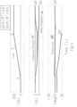
- Fig. 5 shows the control characteristics when the phase error estimation unit in the low-speed range 9 is not used ( ⁇ Q c_H is used).
- the upper row shows the load torque T L
- the middle row shows the frequency command ⁇ r * and the motor frequency ⁇ r
- the lower row shows the phase error ⁇ .
- the load torque in the form of a ramp begins to be applied at time point A in the figure and is varied to 100% at time point B. The load torque remains applied from the right after point B.
- first reactive power Q c is calculated from (Formula 6) using the voltage command values v dc **, v qc ** and current detection values i dc , i qc of the d c and q c axes.
- second reactive power Q c ⁇ is calculated from (Formula 7) using the current detection values i dc , i qc , frequency estimates ⁇ dc of the d c and q c axes and the set values of the electrical circuit parameters of magnet motorl (L d *, L q *, K e *).
- phase error estimates ⁇ c_L in the low-speed range are automatically adjusted from (Formula 8) to track the deviation between Q c ⁇ and Q c to zero, which is the result of the calculation, and the estimated value ⁇ _cL is used in the frequency and phase estimation unitl0 to reduce sensitivity to the resistance value, thereby improving control characteristics.
- the control characteristics can be improved.
- the frequency command value ⁇ r * is accelerated from 2% to 20% of the base frequency and decelerated from 20% to 2%. At this time, the frequency command value ⁇ r * switches between the slow speed range and the estimated phase error in the medium and high speed range with a magnitude of 10%.
- the low-speed range where ⁇ r * is less than 10% of the base frequency is calculated using (Formula 8).
- the medium- to high-speed range where ⁇ r * is 10% or more of the base frequency is calculated using (Formula 5).
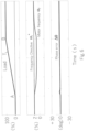
- the switching characteristics from the low-speed range to the medium-high-speed range or from the medium-high-speed range to the low-speed range in this example are shown in Figure 7 .
- ⁇ r * is switched between the low speed range and the estimated phase error in the medium and high speed range at a magnitude of 10% of the base frequency, but there is no problem if ⁇ r * is switched at values above zero and below 10% of the base frequency.
- phase error estimates at low speeds ⁇ c_L may also be multiplied by a taper gain G _L that varies between "1" and "0" and the estimated phase error in the medium and high speed range ⁇ c_H may be the taper gain G _H may be multiplied, respectively, and the average value of the phase error estimates may be ⁇ c .
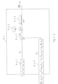
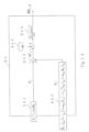
- voltage detector 21 and current detector 22 are attached to the power conversion device 20 that drives magnet motor 1, and encoder 23 is attached to the shaft of magnet motor 1. Encoder 23 is attached to the shaft of magnet motor 1.
- phase error ⁇ _cal is calculated using (Formula 11).
- the power conversion device in position sensor-less control that omits encoder, etc. to detect magnet motor magnet phase, even in the low speed range from stop to about 10% of the base frequency, without adjustment of magnet motor electric circuit parameters and control gain to be set in the control section (controller), the power conversion device can achieve stable and highly accurate control characteristics.
- this example estimates the phase error as in the medium- and high-speed range from the deviation of two types of reactive power. With such a configuration, it is possible to estimate the motor frequency (motor rotation speed) so that the phase error estimates follow its command value in the low-speed range as well as in the medium- and high-speed range, thereby preventing torque shock.
- Fig. 9 shows the system configuration with power conversion device and magnet motor in example 2.
- the phase error estimation unit in the low-speed range 9 calculated the first reactive power Q c from the voltage command values v dc ** and v qc ** of the d c and q c axes and the current detection values i dc and i qc .
- the first reactive power calculation section 9a1 calculates first reactive power Q c as the output voltage of magnet motor 1 by using the amplitude value V 1 * of the voltage command for one phase of three-phase AC, the amplitude value i 1 of the current detection and the sine signal of the phase difference ⁇ vi between the voltage command and current detection values.
- the magnet motorl to phase error estimation in the medium and high-speed, range 8, frequency and phase estimation unit 10, and coordinate conversion unit 11 in Fig 9 are identical to those in Fig. 1 .
- the same details as in example 1 are omitted.
- Fig. 10 shows the phase error estimation unit 9a in the low-speed range in this example.
- the functional block in Fig. 10 corresponds to the phase error estimation unit in the low-speed range 9 in Fig. 2 .
- the second reactive power calculation section 9a2, subtraction section 9a3, command value of deviation of reactive power 9a4, and PI control section 9a5 in Fig. 10 are identical to the second reactive power calculation section 92, subtraction section 93, command value of deviation of reactive power 94, and PI control section 95 in Fig. 3 .
- the first reactive power calculation section 9a1 calculates the amplitude value V 1 * of the voltage command of three-phase AC from (Formula 12), the amplitude value i 1 of the current detection value from (Formula 13), and the phase ⁇ vi from (Formula 14). Then, using (Formula 15), reactive power Q c is calculated using the voltage amplitude value V 1 * of one phase of three-phase AC as the output voltage of magnet motorl, the current amplitude value i 1 and the sine signal of the phase difference between the voltage command and current detection value ⁇ vi .
- the amount of calculation can be reduced because there are fewer parameters to calculate first reactive power Q c than in example 1.
- This example which is an AC quantity, can be used to achieve the same high-precision control characteristics as in example 1.
- Fig. 11 shows a system configuration diagram with a power conversion device and magnet motor in example 3.
- the phase error estimates ⁇ c_H in the medium and high-speed range are calculated in the phase error estimation in the medium and high-speed range 8 according to (Formula 5).
- the estimation calculation section 8a of the phase error in the medium and high-speed range calculates the first active power P c from the voltage command values v dc ** and v qc ** of the d c and q c axes and the current detection values i dc and i gc .
- Fig. 12 shows the configuration of the phase error estimation calculation section 8a in the medium and high-speed range in example 3.
- Fig. 12 corresponds to phase error estimation in the medium and high-speed range8 in Fig. 1 .
- Fig. 11 is identical to those in Fig. 1 .
- Fig. 11 is the same as Fig. 1 .
- the same contents as in example 1 or example 2 are omitted.
- the second active power calculation section 8a2 calculates the second active power P c ⁇ according to (Formula 17) using the current detection values i dc , i qc , frequency estimates ⁇ dc , and electrical circuit parameters of magnet motorl (R* , L d *, L q * , K e * ) for the d c and q c axes.
- P c ⁇ R * i dc 2 + i qc 2 + ⁇ dc L d * ⁇ L q * i dc i qc + ⁇ dc K e * i qc
- the first active power P c and second active power P c ⁇ are input to the subtraction section 8a3, and the deviation ⁇ P c , is calculated.
- the difference between the deviation of the active power ⁇ P c and the command value of the deviation of the active power is input to the PI control section 8a5 so that the deviation of the active power ⁇ P c , follows "0" which is the command value of the deviation of the active power 8a4.
- the PI control section 8a5 calculates the estimated value ⁇ c_H of the phase error ⁇ in the medium to high speed range according to (Formula 18) by P(proportional)+I(integral) control.
- ⁇ c _ H K p ⁇ + K i ⁇ s 0 ⁇ ⁇ P c
- K p ⁇ proportional gain of the phase error estimation calculation
- K i ⁇ integral gain of the phase error estimation calculation
- the.estimation calculation of the phase error in the medium to high speed range can be performed without being affected by the estimation error of inductance because the set value of inductance is not used. It also has the same effect as in example 1.
- Fig. 13 shows the system configuration with power conversion device and magnet motor in example 4.
- first active power P c was calculated from the voltage command values v dc ** and v qc ** of the d c and q c axes and current detection values i dc and i qc .
- the first active power calculation unit 9b1 calculates the first active power P c using the amplitude value V 1 *of the three-phase AC voltage command and the cosine signals of the amplitude value ii and phase ⁇ vi of the current detection. The same details as in examples 1 through 3 are omitted.
- Fig. 14 shows the phase error estimation calculation section 8b in the medium and high-speed range in example 3.
- Fig. 14 corresponds to the phase error estimation in the medium and high-speed range 8 in Fig. 2 .
- magnet motor 1 to vector control arithmetic unit 7 and phase error estimation unit in the low-speed range 9 to coordinate conversion unit 11 are identical to those in Fig. 1 .
- Fig. 13 is identical to Fig. 1 .
- the second active power calculation section 8b2, subtraction section 8b3, command value of deviation of active power 8b4, and PI control section 8b5 in Fig. 14 are identical to the second active power calculation section 8a2, subtraction section 8a3, command value of deviation of active power 8a4, and PI control section 8a5 in Fig. 12 .
- the estimation calculation of the phase error in the medium to high-speed range can be performed without being affected by the estimation error of the inductance, compared to example 1.
- This example can be used to achieve the same high-precision control characteristics as in example 1.
- Fig. 15 shows a system configuration diagram with power conversion device, magnet motor, and internet of things (IOT) controller in example 5.
- IOT internet of things
- the electrical circuit parameters of magnet motor 1 are set in the controller of the power converter (e.g., microcomputer), but in this example, the control state quantities are feedback to the upper IOT controller and the machine-learned electrical circuit parameters are re-set to the power converter controller.
- the controller of the power converter e.g., microcomputer
- IOT controller 12 is an IOT controller that performs machine learning. The same details as in examples 1 through 4 are omitted.
- the voltage command values v dc **, v qc ** and current detection values i dc , i qc , phase error estimates ⁇ c are feedback to the higher-level IOT controller 12 for machine learning from current detection waveforms and other data.
- the machine-learned electric circuit parameters (R*, L d *, L q *, K e *) are re-set to the controller of power converter2, the control unit.
- the electrical circuit parameters can be re-set from the higher-level IOT controller 12 through machine learning of the operating conditions.
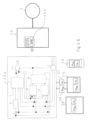
- Fig. 16 is a system configuration diagram with power conversion device, magnet motor, personal computers, tablets, smartphones, and other devices in example 6.
- This example is the application of this example to a magnet motor drive system.
- the components magnet motor 1, coordinate conversion unit 5 to coordinate conversion unit 11 are identical to those in Fig. 1 .
- the same contents as in examples 1 to 5 are omitted from the explanation.
- Magnet motor 1 a component of Fig. 16 , is driven by power conversion device 20.
- Power conversion device 20 includes coordinate conversion unit 5, speed control arithmetic unit 6, vector control arithmetic unit 7, phase error estimation in the medium and high-speed range 8, and phase error estimation unit in the low-volume range 9.
- frequency and phase estimation unit10, and coordinate conversion unit11 of Fig.1 are implemented as software 20a.
- the power converter 2, DC power supply 3, and current detector 4 of Fig. 1 are implemented as hardware in the power conversion device 20.
- the software 20a "switching frequency in the low-speed/medium-high-speed range.26 ⁇ chg " and “phase error control response in the slow range.27, ⁇ c " can be set and changed by higher-level devices such as the digital operator 20b, personal computers 28, tablets 29, smartphones 30, etc.
- the switching frequency in the low-speed/medium-high-speed range 26, ⁇ chg is input to the frequency and phase estimation unit10 shown in Fig. 4 from a higher-level device such as personal computers 28, tablets 29 and smartphones 30.
- the frequency and phase estimation unit 10 is configured to including compare part which compare the frequency command value ⁇ r * input to the frequency and phase estimation unit 10 and the switching frequency in the low-speed/medium-high -speed range 26, ⁇ chg .
- phase errorcontrol response in the slow range.27, ⁇ c is input to the phase error estimation unit in Fig. 3 from a higher-level device such as personal computers 28, tablets 29, smartphones 30, etc.
- the gains of the PI control unit 95, Kp pll (proportional gain of PLL control) and Ki pll (integral gain of PLL control) in (Formula 9), can be controlled based on the phase error control response in the slow range ⁇ c
- the ⁇ c " may be set up on a fieldbus such as a programmable logic controller, a local area network connecting to a computer, or an IOT controller.
- the configuration of the power conversion device is not limited to example 1 but may use the configurations of examples 2 through 5.
- setting values such as switching frequency in the low-speed/medium-high-speed range26 can be changed from outside the power conversion device. Also in this example, as in example 1, more stable and precise control characteristics can be achieved.
- the current detection values i dc and i qc were used for first reactive power Q c (Formula 6) and second reactive power Q c ⁇ (Formula 7), but the current command values i d * and i q * may be used.
- the current detection values i dc and i qc were used for the first active power P c (Formula 16) and second active power P c ⁇ (Formula 17), but the current command values i d * and i q * may also be used.
- examples 1 through 5 the operations shown in (Formula 4) were performed to create voltage correction values ⁇ v dc and ⁇ v qc from current command values i d *, i q * and current detection values i dc , i qc and to add these voltage correction values and the voltage reference value for vector control.
- intermediate current command values i d ** and i q ** shown in (Formula 20) used for vector control calculation are created from current command values i d * and i q * and current detection values i dc and i qc
- vector control calculation shown in (Formula 21) may be performed using frequency estimates ⁇ dc and magnet motorl electric circuit parameters.
- the voltage correction values ⁇ v d_p * for the proportional component of d c axis, ⁇ v d_i * for the integral component of d c axis, ⁇ v q_p * for the proportional component of q c axis, and ⁇ v q_i * for the integral component of q c axis are created using (Formula 22) and the estimated frequency value ⁇ dc and the electrical circuit parameters of magnet motorl may be used to perform the vector control operations shown in (Formula 23).
- the vector control operation shown in (Formula 24) may also be performed using the primary delay signal i qctd of the current command value i d * of the d c axis and the current detection value i qc of the q c axis, frequency estimates ⁇ dc and the electrical circuit parameters of magnet motor 1.
- the switching device that constitutes power converter 2 may be a Si (silicon) semiconductor device or a wide bandgap semiconductor device such as SiC (silicon carbide) or GaN (gallium nitride).
Landscapes
- Engineering & Computer Science (AREA)
- Power Engineering (AREA)
- Control Of Ac Motors In General (AREA)
- Control Of Motors That Do Not Use Commutators (AREA)
- Amplifiers (AREA)
- Polarising Elements (AREA)
- Inverter Devices (AREA)
Abstract
Description
- This invention relates to power conversion devices.
- As a stable and highly accurate control method in the low-speed range of position sensorless control, there is a technique, as described in the
patent document 1, to estimate the frequency of the magnet motor by calculating the reactive power based on the voltage command value to the power converter, current detection value, electric circuit parameters of the magnet motor, and frequency estimates. The frequency of the magnet motor is estimated by calculating the reactive power based on the voltage command to the power converter, current detection, electric circuit parameters of the magnet motor, and frequency estimates. -
Patent Documents 1Japanese Unexamined Patent Publication No. 2006-197712 - The technology described in the
literature 1 calculates two kinds of reactive power (Q and Q hat) and calculates frequency estimates of the inverter to set the deviation ΔQ to zero. This allows the frequency estimates to be less sensitive to temperature changes in the magnet motor winding resistance, resulting in highly accurate control characteristics. - By the way, there are cases where speed control is performed using different techniques for high frequency (medium-high speed) and low frequency (low speed). In such cases, for example, in the low-speed range, the first motor frequency is estimated so that the deviation ΔQ is zero by calculating two types of reactive power using the technology of
Patent Document 1. On the other hand, in the medium to high speed range, for example, another technique is used to estimate the phase error (phase of control and magnet motor) using the extended induced voltage, and the second motor frequency is estimated by PI control to follow the zero. When the first motor frequency and the second motor frequency are switched between the low-speed range and the medium- to high-speed range, if there is a difference between the two frequencies, torque shock (torque fluctuation) due to current change may occur. - In addition, by making the magnet motor less sensitive to temperature changes in the magnet motor winding resistance, stable and highly accurate control characteristics are required without the need to adjust electrical circuit parameters such as resistance values.
- The purpose of this invention is to provide a power conversion device with stable and accurate control characteristics that can prevent torque shock when the motor frequency changes and does not require adjustment of electrical circuit parameters.
- Present invention is a power conversion device comprising a power converter outputting signals to the motor to vary the output frequency, output voltage and output current of the motor, a control unit controlling the power converter wherein the control unit is calculating the first power from the output voltage and the output current, calculating the second power from the output current, electrical circuit parameters and a frequency estimates, calculating the first phase error estimate in a first frequency domain so that the first power follows the second power, calculating the second phase error estimate in a second frequency domain different from the first frequency domain, controlling the frequency estimates so that the first phase error estimate or the second phase error estimate follows the command value of the phase error estimate.
- The invention can prevent torque shock when the motor frequency changes, as well as provide stable and highly accurate control characteristics without the need to adjust electrical circuit parameters.
-
-
Fig. 1 : System configuration diagram of power conversion device and other devices in example 1. -
Fig. 2 : Configuration diagram of the estimation calculation section of the phase error using the extended induced voltage in the high-speed range. -
Fig. 3 : Configuration diagram of the estimation calculation section of the phase error in the low-speed range in example 1. -
Fig. 4 : Configuration diagram of the frequency and phase estimation unit in example 1. -
Fig. 5 : Control characteristics when the extended induced voltage method for the medium and high-speed range is used in the low speed range. -
Fig. 6 : Control characteristics in example 1. -
Fig. 7 : Control characteristics when switching between low-speed and medium-high-speed ranges in example 1. -
Fig. 8 Configuration diagram for checking the manifestation of the invention. -
Fig. 9 : System configuration diagram of power conversion device, etc. in example 2. -
Fig. 10 : Configuration diagram-of the phase error estimation unit in the low-speed range in example 2. -
Fig. 11 : System configuration diagram of power conversion device, etc. in example 3. -
Fig. 12 : Configuration diagram of the phase error estimation in the medium and high-speed range in example 3. -
Fig. 13 : System configuration diagram of power conversion device, etc. in Example 4. -
Fig. 14 : Diagram of the estimation calculation section of the phase error in the medium and high-speed range in example 4. -
Fig. 15 : System configuration diagram of power conversion device, etc. in example 5. -
Fig. 16 : System configuration diagram of power conversion device and other devices in example 6. - The following drawings are used to explain this example in detail. The same reference numbers are used for common configurations in each figure. The examples described below are not limited to the illustrated examples.
-
Fig. 1 shows the system configuration with power conversion device and magnet motor in example 1. - The power conversion device in this example achieves stable and highly accurate control characteristics even in the low-speed range, which is about 10% of the base frequency from standstill, in position sensor-less control that omits encoders and other devices that detect the magnet motor's magnet phase.
-
Magnet motor 1 outputs motor torque that is a composite of the torque component due to the magnetic flux of the permanent magnet and the torque component due to the inductance of the armature winding. -
Power converter 2 is equipped with semiconductor devices as switching elements.Power converter 2 inputs 3-phase ac voltage command values vu*, vv* and vw* and outputs voltage values proportional to 3-phase ac voltage command values vu*, vv* and vw*. Based on the output ofpower converter 2, magnet motorl is driven and the output voltage value, output frequency value and output current of magnet motorl are controlled variably. Insulated gate bipolar transistor (IGBT) may be used as switching element. -
DC power supply 3 supplies DC voltage and DC current topower converter 2. - The
current detector 4 outputs iuc, ivc and iwc, which are the detected three phases AC currents iu, iv and iw of themagnet motor 1. Thecurrent detector 4 also detects the three phases AC currents of two of the magnet motorl, e.g., phase u and phase w. The AC current of phase v may be obtained from the AC condition (iu+iv+iw=0) as iv=-(iu+iw). - In this example, the
current detector 4 is shown in the power conversion device, but it can also be located outside the power conversion device. - The control unit includes
coordinate conversion unit 5, speed controlarithmetic unit 6, vector controlarithmetic unit 7, phase error estimation in the medium and high-speed range 8, phase error estimation unit in the low-speed range .9, frequency and phase estimation unit10, and coordinate conversion unit11. The control unit controls the output ofpower converter 2 so that the output voltage value, output frequency value and output current of magnet motorl are controlled variably. - The control section is composed of semiconductor integrated circuits (arithmetic and control means) such as microcomputer and digital signal processor (DSP). Any or all of the control section can be implemented by hardware such as an ASIC (Application Specific Integrated Circuit) or FPGA (Field Programmable Gate Array). The CPU (Central Processing Unit) of the control section reads a program held in a memory or other recording device and executes the processing of each part such as the
coordinate conversion unit 5 described above. - Next, each component of the control unit is described.
- Coordinate
conversion unit 5 outputs d-axis and q-axis current detection values idc and iqc from the detected values iuc, ivc, and iwc of the three phase AC currents iu, iv, and iw and the phase estimate θdc. - The speed control
arithmetic unit 6 calculates the torque command value τ* based on the frequency command value ωr* and frequency estimates ωdc, and outputs the q-axis current command value iq* by dividing by the torque factor. The frequency command value ωr* is used to determine the medium to high speed range and low speed range, and frequency estimates ωdc corresponds to the motor speed estimate (motor rotation speed estimate). - Vector control
arithmetic unit 7 outputs d-axis and q-axis current command values id*, iq*, current detection values idc, iqc , frequency estimates ωdc and d-axis and q-axis voltage calculated based on the electrical circuit parameters of magnet motorl command value vdc** and vqc** are output. - The phase error estimation in the medium and high-
speed range 8 uses the voltage command values vdc**, vqc**, frequency estimates ωdc, current detection values idc, iqc and electrical circuit parameters ofmagnet motor 1 for the dc and qc axes, which are control axes. The estimated value Δθc_H of phase error Δθ, which is the deviation between the phase θdc of control in the medium and high speed range and the phase θd of themagnet motor 1 is output. - The phase error estimation unit in the low-
speed range 9 uses the voltage command values vdc**, vqc** , frequency estimates ωdc, current detection values idc, iqc and electrical circuit parameters of magnet motor1 for the dc and qc axes, which are control axes. The estimated value Δθc_L of the phase error Δθ, which is the deviation between the phase θdc of the control and the phase θd of the magnet motorl in the low speed range, is calculated. - The frequency and
phase estimation unit 10 is based on the phase error estimates at low speedsΔθc_L or the estimated phase error in the medium and high speed rangeΔθc_H , frequency estimates ωdc and phase estimatesθdc are output. - The coordinate conversion unit 11 outputs the voltage command values vu*, vv* and vw* for 3-phase AC from the voltage command values vdc** and vqc** for the dc and qc axes and the phase estimate value θdc.
- First, the basic operation of the sensor-less vector control scheme when using the phase error estimation unit in the low-
speed range 9 is described. - The speed control
arithmetic unit 6 calculates the torque command τ* and the q-axis current command iq* according to (Formula 1) using proportional control and integral control so that the frequency estimates ωdc follow the frequency command value ωr*.
[Formula 1]
- The vector control
arithmetic unit 7 firstly uses the electrical circuit parameters of the permanent magnet motor 1: the set value of winding resistance R*, the set value of d-axis inductance Ld*, the set value of q-axis inductance Lq*, the value of induced voltage coefficient Ke*, the current command values id* and iq* for the dc axes and qc axes and frequency estimatesωdc to output the voltage reference values vdc* and vqc* for the dc and qc axes according to (Formula 2).
[Formula 2]
- Second, vector control
arithmetic unit 7 calculates the voltage correction values Δvdc and Δvqc for the dc and qc axes according to (Formula 3) using proportional and integral control so that the current detection values idc and iqc for each component follow the current command values id* and iq* for the dc and qc axes.
[Formula 3]
- Furthermore, vector control
arithmetic unit 7 calculates the voltage command values vdc** and vqc** for the dc and qc axes according to (Formula 4).
[Formula 4]
-
Fig. 2 shows the block of phase error estimation in the medium and high-speed range 8. - Phase error estimation in the medium and high-
speed range 8 is based on the voltage command values vdc**, vqc** of dc axis and qc and current detection values idc and iqc and the electrical circuit parameters of magnet motor 1 (R* and Lq*), the calculation section 81 of the phase error estimates in the medium and high-speed range using the extended induced voltage method calculates the phase error estimates Δθc_H in the medium and high-speed range according to (Formula 5).
[Formula 5]
- The phase error estimation unit in the low-
speed range 9 is explained here.Figure 3 shows the blocks of the phase error estimation unit in the low-speed range 9. - The phase error estimation unit in the low-speed ranges calculates the first reactive power Qqc** in the first reactive power calculation unit91 using the voltage command values vdc** of the dc axis and v of the qc axis as the output voltage of magnet motorl and the voltage command values v of the q axis as the output current of magnet motorl The first reactive power Qc is calculated according to (Formula 6) using the current detection values idc of the dc axis and iqc of the qc axis as the output current of magnet motorl.
[Formula 6]
- The second reactive
power calculation section 92 calculates the second reactive power Qc ^ using the current detection values idc of the dc axis and the current detection values iqc of the qc axis, frequency estimates ωdc and the electrical circuit parameters of magnet motorl (Ld* , Lq * and Ke* ) according to (Formula 7) .
[Formula 7]
- The first reactive power Qc and second reactive power Qc ^ are input to the
subtraction section 93, and the deviation, ΔQc, is calculated. The deviation of reactive power, ΔQc, is input to PI control calculation section 95 (hereinafter referred to as PI control section) to follow the command value ofreactive power deviation 94 which is "0." ThePI control section 95 calculates the estimated-value of phase error Δθc_L of the phase error Δθ in the low speed range according to (Formula 8) using P (proportional) + I (integral) control calculation.
[Formula 8]
- The frequency and
phase estimation unit 10 is described below.Fig. 4 shows the blocks of frequency andphase estimation unit 10. - The
switching section 101 receives the phase error estimates Δθc_L in the low-speed range, the phase error estimates Δθc_H in the medium- to high-speed range, and the frequency command value ωr*. Theswitching section 101 outputs Δθc=Δθc_L for the low-speed range and Δθc=Δθc_H for the medium- to high-speed range as phase error estimates Δθc depending on the magnitude of the frequency command value ωr*. - In the
subtraction section 103, the deviation between the phase error estimate Δθc and Δθc* is input to thePI control section 104 so that the aforementioned phase error estimates Δθc tracks the phase error command value Δθc* 102. ThePI control section 104 uses P (proportional) + I (integral) control operations to the frequency estimatesωdc is calculated according to (Formula 9). In addition, the I control arithmetic section (I control section) 105 calculates the phase estimate θdc according to (Formula 10) based on the output of thePI control section 104.
[Formula 9]
[Formula 10]
- The principle of the stable and highly accurate control characteristics of the present invention will be explained next.
-
Fig. 5 shows the control characteristics when the phase error estimation unit in the low-speed range 9 is not used (ΔQc_H is used). The frequency command value ωr* is set to 2% of the base frequency. (when there is no error in the voltage command values vdc** and vqc** of the dc and qc axes shown in (Formula 2) and the set value R* of the resistance value R included in the calculation formula for the phase error in the medium- and high-speed range shown in (Formula 5), (a) R*/R=1 (base). - The simulation results of (a) and (b) are shown in
Fig. 5 , assuming (b) R*/R=0.5 when there is an error in the resistance R setting R*. - In
Fig. 5 , the upper row shows the load torque TL, the middle row shows the frequency command ωr* and the motor frequency ωr, and the lower row shows the phase error Δθ. The load torque in the form of a ramp begins to be applied at time point A in the figure and is varied to 100% at time point B. The load torque remains applied from the right after point B. - (a) When R*/R=1 (reference) is set, the phase error Δθ is zero at steady state and the motor frequency ωr matches the frequency command ωr*. (b) When R*/R=0.5 is set, the phase error Δθ increases "negatively" and the motor frequency ωr is stagnant near zero and magnet motorl is out of step.
- In this example, first reactive power Qc is calculated from (Formula 6) using the voltage command values vdc**, vqc** and current detection values idc, iqc of the dc and qc axes. In addition, second reactive power Qc ^ is calculated from (Formula 7) using the current detection values idc, iqc, frequency estimates ωdc of the dc and qc axes and the set values of the electrical circuit parameters of magnet motorl (Ld*, Lq*, Ke*).
- The phase error estimates Δθc_L in the low-speed range are automatically adjusted from (Formula 8) to track the deviation between Qc ^ and Qc to zero, which is the result of the calculation, and the estimated value Δθ _cL is used in the frequency and phase estimation unitl0 to reduce sensitivity to the resistance value, thereby improving control characteristics. The control characteristics can be improved.
- The control characteristics in the low-speed range for this example are shown in
Fig. 6 , where R*/R=0.5, the phase error estimation unit in the low-speed range 9 and the frequency andphase estimation unit 10 are operated and the same load torque is applied as inFig. 5 . The actual phase error Δθ can be suppressed to zero even when R*/R=0.5 because the phase error estimates Δθc_L are calculated by reactive power with low sensitivity to the resistance value R. - Furthermore, in this example, the frequency command value ωr* is accelerated from 2% to 20% of the base frequency and decelerated from 20% to 2%. At this time, the frequency command value ωr* switches between the slow speed range and the estimated phase error in the medium and high speed range with a magnitude of 10%.
- The low-speed range where ωr* is less than 10% of the base frequency is calculated using (Formula 8). The medium- to high-speed range where ωr* is 10% or more of the base frequency is calculated using (Formula 5). The switching characteristics from the low-speed range to the medium-high-speed range or from the medium-high-speed range to the low-speed range in this example are shown in
Figure 7 . - As shown in the middle row of
Fig. 7 , in the C region, the switching is made from the low-speed region to the medium-high-speed region, and in the D region, the switching is made from the medium-high-speed region to the low-speed region. Looking at the phase error Δθ in the lower row, the magnitude changes somewhat depending on the timing of the switching, but there is no shock to the motor frequency ωr and no shock to the torque, indicating that the effect of this example is obvious. - In this example, ωr* is switched between the low speed range and the estimated phase error in the medium and high speed range at a magnitude of 10% of the base frequency, but there is no problem if ωr* is switched at values above zero and below 10% of the base frequency.
- The phase error estimates at low speeds Δθc_L may also be multiplied by a taper gain G_L that varies between "1" and "0" and the estimated phase error in the medium and high speed range Δθc_H may be the taper gain G_H may be multiplied, respectively, and the average value of the phase error estimates may be Δθc.
- Here, the verification method when this example is adopted is explained using
Fig. 8 . voltage detector 21 andcurrent detector 22 are attached to thepower conversion device 20 that drivesmagnet motor 1, andencoder 23 is attached to the shaft ofmagnet motor 1.Encoder 23 is attached to the shaft ofmagnet motor 1. - In calculation unit of vector voltage and
current components 24, three-phase AC voltage detection values (vuc , vvc , vwc ) which are outputs of voltage detector 21 and three-phase AC current detection values (iuc , ivc , iwc ) and position θ which is output of the encoder are input, and the vector voltage components vdc, vqc, the vector current components idc, iqc and the detected value ωdc differentiated by position θ are calculated. - In the observation of waveforms of each part 25, the phase error Δθ_cal is calculated using (Formula 11).
[Formula 11]
- By changing the magnitude of the parameters (R*, Ld *, L q*, Ke*) set in the controller of
power converter 2, Δθ_cal in (Formula 11) 'is calculated, and if it matches the actual phase error Δθ, it is evident that the invention is adopted. - According to this example, in position sensor-less control that omits encoder, etc. to detect magnet motor magnet phase, even in the low speed range from stop to about 10% of the base frequency, without adjustment of magnet motor electric circuit parameters and control gain to be set in the control section (controller), the power conversion device can achieve stable and highly accurate control characteristics.
- Furthermore, in the low-speed range, instead of estimating the motor frequency as in the
patent document 1, this example estimates the phase error as in the medium- and high-speed range from the deviation of two types of reactive power. With such a configuration, it is possible to estimate the motor frequency (motor rotation speed) so that the phase error estimates follow its command value in the low-speed range as well as in the medium- and high-speed range, thereby preventing torque shock. -
Fig. 9 shows the system configuration with power conversion device and magnet motor in example 2. - In example 1, the phase error estimation unit in the low-
speed range 9 calculated the first reactive power Qc from the voltage command values vdc** and vqc** of the dc and qc axes and the current detection values idc and iqc. In this example, the first reactive power calculation section 9a1 calculates first reactive power Qc as the output voltage ofmagnet motor 1 by using the amplitude value V1* of the voltage command for one phase of three-phase AC, the amplitude value i1 of the current detection and the sine signal of the phase difference θvi between the voltage command and current detection values. - The magnet motorl to phase error estimation in the medium and high-speed,
range 8, frequency andphase estimation unit 10, and coordinate conversion unit 11 inFig 9 are identical to those inFig. 1 . The same details as in example 1 are omitted. -
Fig. 10 shows the phase error estimation unit 9a in the low-speed range in this example. The functional block inFig. 10 corresponds to the phase error estimation unit in the low-speed range 9 inFig. 2 . - The second reactive power calculation section 9a2, subtraction section 9a3, command value of deviation of reactive power 9a4, and PI control section 9a5 in
Fig. 10 are identical to the second reactivepower calculation section 92,subtraction section 93, command value of deviation ofreactive power 94, andPI control section 95 inFig. 3 . - In the same figure, the first reactive power calculation section 9a1 calculates the amplitude value V1* of the voltage command of three-phase AC from (Formula 12), the amplitude value i1 of the current detection value from (Formula 13), and the phase θvi from (Formula 14). Then, using (Formula 15), reactive power Qc is calculated using the voltage amplitude value V1* of one phase of three-phase AC as the output voltage of magnet motorl, the current amplitude value i1 and the sine signal of the phase difference between the voltage command and current detection value θvi.
[Formula 12]
[Formula 13]
[Formula 14]
[Formula 1 5]
- According to this example, the amount of calculation can be reduced because there are fewer parameters to calculate first reactive power Qc than in example 1.
- This example, which is an AC quantity, can be used to achieve the same high-precision control characteristics as in example 1.
-
Fig. 11 shows a system configuration diagram with a power conversion device and magnet motor in example 3. In example 1, the phase error estimates Δθc_H in the medium and high-speed range are calculated in the phase error estimation in the medium and high-speed range 8 according to (Formula 5). - In example 3, the estimation calculation section 8a of the phase error in the medium and high-speed range calculates the first active power Pc from the voltage command values vdc** and vqc** of the dc and qc axes and the current detection values idc and igc.
-
Fig. 12 shows the configuration of the phase error estimation calculation section 8a in the medium and high-speed range in example 3.Fig. 12 corresponds to phase error estimation in the medium and high-speed range8 inFig. 1 . - The magnet motorl to vector control
arithmetic unit 7, phase error estimation unit in the low-speed range 9 to frequency andphase estimation unit 10 inFig. 11 are identical to those inFig. 1 .Fig. 11 is the same asFig. 1 . The same contents as in example 1 or example 2 are omitted. - In the phase error estimation in the medium and high-speed range 8a in
Fig. 12 , the first active power calculation section 8al uses the voltage command values vdc** and vqc** for the dc and qc axes and the current detection values idc and iqc for the dc and qc axes to calculate first active power Pc is calculated according to (Formula 16).
[Formula 16 ]
- The second active power calculation section 8a2 calculates the second active power Pc ^ according to (Formula 17) using the current detection values idc, iqc, frequency estimates ωdc, and electrical circuit parameters of magnet motorl (R* , Ld*, Lq * , Ke* ) for the dc and qc axes.
[Formula 1 7]
- The first active power Pc and second active power Pc ^ are input to the subtraction section 8a3, and the deviation ΔPc, is calculated. The difference between the deviation of the active power ΔPc and the command value of the deviation of the active power is input to the PI control section 8a5 so that the deviation of the active power ΔPc, follows "0" which is the command value of the deviation of the active power 8a4.
- The PI control section 8a5 calculates the estimated value Δθc_H of the phase error Δθ in the medium to high speed range according to (Formula 18) by P(proportional)+I(integral) control.
[Formula 18 ]
- According to this example, compared to the estimation calculation of the phase error in the medium to high-speed range using the extended induced voltage method of example 1, the.estimation calculation of the phase error in the medium to high speed range can be performed without being affected by the estimation error of inductance because the set value of inductance is not used. It also has the same effect as in example 1.
-
Fig. 13 shows the system configuration with power conversion device and magnet motor in example 4. - In example 3, first active power Pc was calculated from the voltage command values vdc** and vqc** of the dc and qc axes and current detection values idc and iqc.
- In this example, the first active power calculation unit 9b1 calculates the first active power Pc using the amplitude value V1*of the three-phase AC voltage command and the cosine signals of the amplitude value ii and phase θvi of the current detection. The same details as in examples 1 through 3 are omitted.
-
Fig. 14 shows the phase error estimation calculation section 8b in the medium and high-speed range in example 3.Fig. 14 corresponds to the phase error estimation in the medium and high-speed range 8 inFig. 2 . InFig. 13 ,magnet motor 1 to vector controlarithmetic unit 7 and phase error estimation unit in the low-speed range 9 to coordinate conversion unit 11 are identical to those inFig. 1 .Fig. 13 is identical toFig. 1 . - The second active power calculation section 8b2, subtraction section 8b3, command value of deviation of active power 8b4, and PI control section 8b5 in
Fig. 14 are identical to the second active power calculation section 8a2, subtraction section 8a3, command value of deviation of active power 8a4, and PI control section 8a5 inFig. 12 . - In
Fig. 14 , the first active power calculation section 9b1 calculates the amplitude value V1* of the voltage command for three-phase AC, using (Formula 12) and the amplitude value i1 of the current detection value, using (Formula 13), and the phase difference θvi between the voltage command and current detection values using (Formula 14). Then, the first active power calculation section 9b1 calculates the first active power Pc using the cosine signals of the voltage amplitude value V1* and current amplitude value i1 for one phase of three-phase AC and the phase difference θvi between the voltage command value and the current detection value using (Formula 19).
[Formula 19 ]
- According to this example, as in example 3, the estimation calculation of the phase error in the medium to high-speed range can be performed without being affected by the estimation error of the inductance, compared to example 1.
- This example can be used to achieve the same high-precision control characteristics as in example 1.
-
Fig. 15 shows a system configuration diagram with power conversion device, magnet motor, and internet of things (IOT) controller in example 5. - In examples 1 through 4, the electrical circuit parameters of
magnet motor 1 are set in the controller of the power converter (e.g., microcomputer), but in this example, the control state quantities are feedback to the upper IOT controller and the machine-learned electrical circuit parameters are re-set to the power converter controller. - The magnet motorl to coordinate conversion unit11 in
Fig. 15 is identical to each functional block inFig. 1 . IOT controller 12 is an IOT controller that performs machine learning. The same details as in examples 1 through 4 are omitted. - In this example, the voltage command values vdc**, vqc** and current detection values idc, iqc, phase error estimates Δθc are feedback to the higher-level IOT controller 12 for machine learning from current detection waveforms and other data. The machine-learned electric circuit parameters (R*, Ld*, Lq*, Ke*) are re-set to the controller of power converter2, the control unit.
- According to this example, the electrical circuit parameters can be re-set from the higher-level IOT controller 12 through machine learning of the operating conditions.
- In this example, as in example 1, more stable and precise control characteristics can be achieved.
-
Fig. 16 is a system configuration diagram with power conversion device, magnet motor, personal computers, tablets, smartphones, and other devices in example 6. - This example is the application of this example to a magnet motor drive system. In the figure, the
components magnet motor 1, coordinateconversion unit 5 to coordinate conversion unit 11 are identical to those inFig. 1 . The same contents as in examples 1 to 5 are omitted from the explanation. -
Magnet motor 1, a component ofFig. 16 , is driven bypower conversion device 20.Power conversion device 20 includes coordinateconversion unit 5, speed controlarithmetic unit 6, vector controlarithmetic unit 7, phase error estimation in the medium and high-speed range 8, and phase error estimation unit in the low-volume range 9. frequency and phase estimation unit10, and coordinate conversion unit11 ofFig.1 are implemented as software 20a. - The
power converter 2,DC power supply 3, andcurrent detector 4 ofFig. 1 are implemented as hardware in thepower conversion device 20. - The software 20a "switching frequency in the low-speed/medium-high-speed range.26 ωchg " and "phase error control response in the slow range.27, ωc " can be set and changed by higher-level devices such as the digital operator 20b,
personal computers 28,tablets 29,smartphones 30, etc. - The switching frequency in the low-speed/medium-high-
speed range 26, ωchg, is input to the frequency and phase estimation unit10 shown inFig. 4 from a higher-level device such aspersonal computers 28,tablets 29 andsmartphones 30. - Then, the frequency and
phase estimation unit 10 is configured to including compare part which compare the frequency command value ωr* input to the frequency andphase estimation unit 10 and the switching frequency in the low-speed/medium-high -speed range 26, ωchg. - If the frequency command value ωr* is lower than the switching frequency in the low-speed/medium-high-
speed range ω chg 26, theswitching section 101 switches its output to Δθc=Δθc_L as the low-speed range. If the frequency command value ωr* is higher than the switching frequency in the low-speed/medium-high-speed range ω chg 26, theswitching section 101 switches so that Δθc=Δθc_H is output as the medium-high-speed range of phase error estimates Δθc. - The phase errorcontrol response in the slow range.27, ωc, is input to the phase error estimation unit in
Fig. 3 from a higher-level device such aspersonal computers 28,tablets 29,smartphones 30, etc. - In such a configuration, the gains of the
PI control unit 95, Kppll (proportional gain of PLL control) and Kipll (integral gain of PLL control) in (Formula 9), can be controlled based on the phase error control response in the slow range ωc - The "switching frequency in the low-speed/medium-high-speed range26 that is ωchg " and the "phase error control response in the slow range.27 The ωc " may be set up on a fieldbus such as a programmable logic controller, a local area network connecting to a computer, or an IOT controller.
- Furthermore,the configuration of the power conversion device is not limited to example 1 but may use the configurations of examples 2 through 5.
- If this example is applied to magnet motor drive systems, highly accurate control characteristics can be achieved in position sensor-less vector control.
- According to example 6, setting values such as switching frequency in the low-speed/medium-high-speed range26 can be changed from outside the power conversion device. Also in this example, as in example 1, more stable and precise control characteristics can be achieved.
- In examples 1 through 5, the current detection values idc and iqc were used for first reactive power Qc (Formula 6) and second reactive power Qc ^ (Formula 7), but the current command values id* and iq* may be used. The current detection values idc and iqc were used for the first active power Pc (Formula 16) and second active power Pc ^ (Formula 17), but the current command values id* and iq* may also be used.
- Furthermore, in examples 1 through 5, the operations shown in (Formula 4) were performed to create voltage correction values Δvdc and Δvqc from current command values id*, iq* and current detection values idc, iqc and to add these voltage correction values and the voltage reference value for vector control. Not limited to that, intermediate current command values id** and iq** shown in (Formula 20) used for vector control calculation are created from current command values id* and iq* and current detection values idc and iqc, and vector control calculation shown in (Formula 21) may be performed using frequency estimates ωdc and magnet motorl electric circuit parameters.
[Formula 2 0]
[Formula 21 ]
- Alternatively, from the current command values id* and iq* and the current detection values idc and iqc , the voltage correction values Δvd_p* for the proportional component of dc axis, Δvd_i* for the integral component of dc axis, Δvq_p* for the proportional component of qc axis, and Δvq_i* for the integral component of qc axis, which are used for vector control calculation, are created using (Formula 22) and the estimated frequency value ωdc and the electrical circuit parameters of magnet motorl may be used to perform the vector control operations shown in (Formula 23).
[Formula 22 ]
[Formula 23 ]
- The vector control operation shown in (Formula 24) may also be performed using the primary delay signal iqctd of the current command value id* of the dc axis and the current detection value iqc of the qc axis, frequency estimates ωdc and the electrical circuit parameters of
magnet motor 1.
[Formula 24 ]
- In examples 1 to 6, the switching device that constitutes
power converter 2 may be a Si (silicon) semiconductor device or a wide bandgap semiconductor device such as SiC (silicon carbide) or GaN (gallium nitride). -
- 1
- magnet motor
- 1
- power converter
- 3
- DC power supply
- 4
- current detector
- 5
- coordinate conversion unit
- 6
- speed control arithmetic unit
- 7
- vector control arithmetic unit
- 8
- phase error estimation in the medium and high-speed range
- 9
- phase error estimation unit in the low-speed range
- 10
- frequency and phase estimation unit
- 11
- coordinate conversion unit
- 20
- power conversion device
- 20a
- power conversion device software part
- 20b
- power conversion device digital operator
- 21
- voltage detector
- 22
- current detector
- 23
- encoder
- 24
- calculation unit of vector voltage and current components
- 25
- observation of waveforms of each part
- 26
- switching frequency in the low-speed/medium-high-speed range
- 27
- phase error control response in the slow range.
- 28
- personal computers
- 29
- tablet
- 30
- smartphones
- id*
- d-axis current command value
- iq*
- q-axis current command value
- ωdc
- frequency estimates
- ωr
- magnet motor frequency
- Vdc*,
- Vdc**, Vdc**, Vdc***, Vdc****, Vdc*****...d-axis voltage command value
- vqc*,
- vqc**, vqc***, vqc***, vqc*****...q-axis voltage command value
- Qc
- first reactive power
- Qc^
- second reactive power
- Pc
- first active power
- Pc^
- second active power
- Δθc_L
- phase error estimates at low speeds
- Δθc_H
- estimated phase error in the medium andhigh speed range
- Δθc
- phase error estimates
Claims (12)
- A power conversion device comprising,a power converter that outputs signal to the motor to vary the motor's output frequency, output voltage and output current and control unit that controls the power converter,the control unit is,calculating the first power from the output voltage and output current,calculating the second power from the output current, electrical circuit parameters and frequency estimates,calculating the first phase error estimate so that the first power follows the second power in the first frequency domain,calculating the second phase error estimate different from the first frequency domain in a second frequency domain,controlling the frequency estimates so that the first phase error estimate or the second phase error estimate follows the command value of the phase error estimate.
- A power conversion device according to claim 1,
the first power and the second power are first reactive power and second reactive power, respectively. - A power conversion device according to claim 2,
the control unit is,calculating the first reactive power based on the d-axis voltage command value, q-axis voltage command value, and the d-axis current detection value and q-axis current detection value,calculating the second reactive power based on the d-axis current detection or current command value, the q-axis current detection or current command value, said motor's electric circuit parameters and the frequency estimates. - A power conversion device according to claim 2,
the control unit is,calculating the first reactive power based on the voltage amplitude value for one phase of three-phase alternating current, current amplitude value and voltage command value and phase difference sine signal of current detection value.calculating the second reactive power based on said motor's electrical circuit parameters, d- and q-axis current detection or current command values, and frequency estimates; - A power conversion device according to claim 1,
the control unit is,calculating the first active power from the output voltage and output current of the motor,calculating the second active power from the motor's electrical circuit parameters, the output current, and the frequency estimates,calculating the second phase error estimate so that the first active power follows the second active power. - A power conversion device according to claim 5,
the control unit is,calculating the first active power based on the d-axis voltage command value, q-axis voltage command value, and the d-axis current detection value and q-axis current detection value,calculating the second active power from said electrical circuit parameters, d-axis current detection or current command value, q-axis current detection or current command value, and frequency estimates for the motor. - A power conversion device according to claim 5,
the control unit is,calculating the first active power based on the voltage amplitude value and current amplitude value for one phase of three-phase AC and the cosine signal of the phase difference between the voltage command value and the current detection value,calculating the second active power based on the electrical circuit parameters, d-axis and q-axis current detection or current command values, and frequency estimates of said motor. - A power conversion device according to claim 1,
the control unit is,
calculating the first phase error estimate by proportional and integral control so that the deviation between the first power and the second power is zero. - A power conversion device according to claim 8,
the control unit is,if the rotation speed of the motor is in the low-speed range, calculating the first reactive power and second reactive power,calculating the first phase error estimate value by proportional and integral control so that the deviation between the first reactive power and the second reactive power is zero,if the rotation speed of the motor is in the medium to high-speed range,calculating the first active power and second active power, and calculating the second phase error estimate value by proportional control and integral control are performed so that the deviation between the first active power and second active power is zero. - A power conversion device according to claim 8,
the control unit is,if the rotation speed of the motor is in the low-speed range, calculating the first reactive power and second reactive power,calculating the first phase error estimate by proportional and integral control so that the deviation between the first reactive power and the second reactive power is zero,if the rotation speed of the motor is in the medium to high-speed range, calculating the second phase error estimate using the extended induced voltage method. - A power conversion device according to claim 1,
the control unit is,feedbacking the output voltage and output current, and the first or second phase error estimate feedback to the IOT controller, which is a high-level device for analysis,modifying the electrical circuit parameters of the motor. - A power conversion device according to claim 1,
the control unit is,
setting or changing a control response set to a frequency value for switching the first frequency domain and the second frequency domain, or for proportional control or integral control for estimating phase error from high-level device.
Applications Claiming Priority (2)
| Application Number | Priority Date | Filing Date | Title |
|---|---|---|---|
| JP2021082831A JP7649196B2 (en) | 2021-05-14 | 2021-05-14 | Power Conversion Equipment |
| PCT/JP2022/002487 WO2022239307A1 (en) | 2021-05-14 | 2022-01-24 | Power conversion device |
Publications (3)
| Publication Number | Publication Date |
|---|---|
| EP4340211A1 true EP4340211A1 (en) | 2024-03-20 |
| EP4340211A4 EP4340211A4 (en) | 2025-04-02 |
| EP4340211B1 EP4340211B1 (en) | 2026-04-15 |
Family
ID=84028336
Family Applications (1)
| Application Number | Title | Priority Date | Filing Date |
|---|---|---|---|
| EP22807014.0A Active EP4340211B1 (en) | 2021-05-14 | 2022-01-24 | Power conversion device |
Country Status (6)
| Country | Link |
|---|---|
| US (1) | US12341448B2 (en) |
| EP (1) | EP4340211B1 (en) |
| JP (1) | JP7649196B2 (en) |
| CN (1) | CN116830450A (en) |
| TW (1) | TWI796948B (en) |
| WO (1) | WO2022239307A1 (en) |
Families Citing this family (2)
| Publication number | Priority date | Publication date | Assignee | Title |
|---|---|---|---|---|
| JP2024074575A (en) * | 2022-11-21 | 2024-05-31 | 株式会社日立産機システム | Power Conversion Equipment |
| JP2025078406A (en) * | 2023-11-08 | 2025-05-20 | 株式会社日立産機システム | Power Conversion Equipment |
Family Cites Families (14)
| Publication number | Priority date | Publication date | Assignee | Title |
|---|---|---|---|---|
| JP2008505596A (en) | 2004-07-01 | 2008-02-21 | インターナショナル レクティファイアー コーポレイション | Method and system for starting permanent magnet synchronous motor drive |
| JP4402600B2 (en) | 2005-01-13 | 2010-01-20 | 株式会社日立製作所 | Synchronous motor drive system and synchronous motor drive method |
| JP4655871B2 (en) * | 2005-10-19 | 2011-03-23 | 株式会社日立製作所 | Field weakening vector control device and module for permanent magnet synchronous motor |
| JP4654217B2 (en) * | 2007-04-25 | 2011-03-16 | 日立オートモティブシステムズ株式会社 | Field weakening control device for permanent magnet motor and electric power steering using the same |
| KR101534518B1 (en) * | 2010-03-08 | 2015-07-07 | 존슨 컨트롤스 테크놀러지 컴퍼니 | Method and system for controlling a permagnent magnet synchronous motor |
| WO2012011155A1 (en) * | 2010-07-23 | 2012-01-26 | 三菱電機株式会社 | Control apparatus and control method for an ac rotary machine |
| JP5413400B2 (en) * | 2011-04-20 | 2014-02-12 | 株式会社安川電機 | AC motor control device |
| JP5644820B2 (en) * | 2012-08-17 | 2014-12-24 | 株式会社安川電機 | Motor control device |
| JP6767213B2 (en) * | 2016-09-05 | 2020-10-14 | 東芝インフラシステムズ株式会社 | Inverter controller and motor drive system |
| JP7699908B2 (en) | 2018-11-20 | 2025-06-30 | 株式会社日立産機システム | Power Conversion Equipment |
| TWI686047B (en) * | 2018-12-13 | 2020-02-21 | 台達電子工業股份有限公司 | Device and method for controlling rotary electric machine |
| JP7194069B2 (en) * | 2019-04-18 | 2022-12-21 | 株式会社日立産機システム | Monitoring device and monitoring method |
| JP7449204B2 (en) * | 2020-09-09 | 2024-03-13 | 株式会社日立産機システム | power converter |
| CN112332445B (en) * | 2020-09-29 | 2022-11-18 | 广西大学 | LCL grid-connected inverter indirect current control method based on instruction current compensation |
-
2021
- 2021-05-14 JP JP2021082831A patent/JP7649196B2/en active Active
-
2022
- 2022-01-24 US US18/274,509 patent/US12341448B2/en active Active
- 2022-01-24 CN CN202280014888.7A patent/CN116830450A/en active Pending
- 2022-01-24 EP EP22807014.0A patent/EP4340211B1/en active Active
- 2022-01-24 WO PCT/JP2022/002487 patent/WO2022239307A1/en not_active Ceased
- 2022-02-11 TW TW111105077A patent/TWI796948B/en active
Also Published As
| Publication number | Publication date |
|---|---|
| JP7649196B2 (en) | 2025-03-19 |
| EP4340211A4 (en) | 2025-04-02 |
| TWI796948B (en) | 2023-03-21 |
| CN116830450A (en) | 2023-09-29 |
| TW202245402A (en) | 2022-11-16 |
| US12341448B2 (en) | 2025-06-24 |
| JP2022175990A (en) | 2022-11-25 |
| US20240097589A1 (en) | 2024-03-21 |
| WO2022239307A1 (en) | 2022-11-17 |
| EP4340211B1 (en) | 2026-04-15 |
Similar Documents
| Publication | Publication Date | Title |
|---|---|---|
| JP5595835B2 (en) | Electric motor drive | |
| CN103155399B (en) | The Current Control gain adjusting method of PM motor, current control method and control device | |
| EP4213370B1 (en) | Power conversion device estimating an induced voltage coefficient | |
| EP4340211A1 (en) | Power conversion device | |
| CN110235355B (en) | Speed estimation method for induction motor and power conversion device using the same | |
| WO2015056541A1 (en) | Drive device for electric motor | |
| JP6199776B2 (en) | Electric motor drive | |
| Dinh et al. | Improved scalar control based on slip compensation from virtual speeds in three-phase induction motor drives | |
| EP4554081A1 (en) | Power conversion device | |
| JP7620286B2 (en) | Motor drive unit | |
| US12334847B2 (en) | Power converter apparatus | |
| US20250062708A1 (en) | Power Converter | |
| EP4625808A1 (en) | Power conversion device | |
| TWI916716B (en) | Power conversion device | |
| JP7689941B2 (en) | Apparatus and method for calculating magnetic pole position correction amount for synchronous motor, and control device for synchronous motor | |
| JP5456873B1 (en) | Synchronous machine controller | |
| Sharifi et al. | Analysis of Induction Machine Drivers in Stationary Reference Frame with Time-Delay Model of Voltage Source Inverters | |
| CN120642203A (en) | Power conversion device | |
| JP2025025869A (en) | Motor drive unit | |
| JP2016195523A (en) | Controller for permanent magnet type synchronous electric motor | |
| WO2022137612A1 (en) | Power conversion device | |
| Mangindaan | Study on Simplified Speed Sensorless Vector Control Systems for Induction Motors | |
| IONEL et al. | Control systems for high power Induction machines |
Legal Events
| Date | Code | Title | Description |
|---|---|---|---|
| STAA | Information on the status of an ep patent application or granted ep patent |
Free format text: STATUS: THE INTERNATIONAL PUBLICATION HAS BEEN MADE |
|
| PUAI | Public reference made under article 153(3) epc to a published international application that has entered the european phase |
Free format text: ORIGINAL CODE: 0009012 |
|
| STAA | Information on the status of an ep patent application or granted ep patent |
Free format text: STATUS: REQUEST FOR EXAMINATION WAS MADE |
|
| 17P | Request for examination filed |
Effective date: 20231214 |
|
| AK | Designated contracting states |
Kind code of ref document: A1 Designated state(s): AL AT BE BG CH CY CZ DE DK EE ES FI FR GB GR HR HU IE IS IT LI LT LU LV MC MK MT NL NO PL PT RO RS SE SI SK SM TR |
|
| RIN1 | Information on inventor provided before grant (corrected) |
Inventor name: TAGUCHI, YOSHIYUKI Inventor name: IWASE, YUTA Inventor name: TOBARI, KAZUAKI |
|
| DAV | Request for validation of the european patent (deleted) | ||
| DAX | Request for extension of the european patent (deleted) | ||
| A4 | Supplementary search report drawn up and despatched |
Effective date: 20250303 |
|
| RIC1 | Information provided on ipc code assigned before grant |
Ipc: H02P 21/22 20160101ALI20250225BHEP Ipc: H02P 27/06 20060101ALI20250225BHEP Ipc: H02P 21/24 20160101ALI20250225BHEP Ipc: H02P 6/18 20160101ALI20250225BHEP Ipc: H02P 21/18 20160101AFI20250225BHEP |
|
| GRAP | Despatch of communication of intention to grant a patent |
Free format text: ORIGINAL CODE: EPIDOSNIGR1 |
|
| STAA | Information on the status of an ep patent application or granted ep patent |
Free format text: STATUS: GRANT OF PATENT IS INTENDED |
|
| INTG | Intention to grant announced |
Effective date: 20251110 |
|
| GRAS | Grant fee paid |
Free format text: ORIGINAL CODE: EPIDOSNIGR3 |
|
| GRAA | (expected) grant |
Free format text: ORIGINAL CODE: 0009210 |
|
| STAA | Information on the status of an ep patent application or granted ep patent |
Free format text: STATUS: THE PATENT HAS BEEN GRANTED |
|
| AK | Designated contracting states |
Kind code of ref document: B1 Designated state(s): AL AT BE BG CH CY CZ DE DK EE ES FI FR GB GR HR HU IE IS IT LI LT LU LV MC MK MT NL NO PL PT RO RS SE SI SK SM TR |
|
| REG | Reference to a national code |
Ref country code: CH Ref legal event code: F10 Free format text: ST27 STATUS EVENT CODE: U-0-0-F10-F00 (AS PROVIDED BY THE NATIONAL OFFICE) Effective date: 20260415 |