EP4340113A1 - Batteriemodul - Google Patents
Batteriemodul Download PDFInfo
- Publication number
- EP4340113A1 EP4340113A1 EP23196743.1A EP23196743A EP4340113A1 EP 4340113 A1 EP4340113 A1 EP 4340113A1 EP 23196743 A EP23196743 A EP 23196743A EP 4340113 A1 EP4340113 A1 EP 4340113A1
- Authority
- EP
- European Patent Office
- Prior art keywords
- battery module
- gas channel
- catalyst
- accumulators
- catalytic converter
- Prior art date
- Legal status (The legal status is an assumption and is not a legal conclusion. Google has not performed a legal analysis and makes no representation as to the accuracy of the status listed.)
- Granted
Links
Images

Classifications
-
- H—ELECTRICITY
- H01—ELECTRIC ELEMENTS
- H01M—PROCESSES OR MEANS, e.g. BATTERIES, FOR THE DIRECT CONVERSION OF CHEMICAL ENERGY INTO ELECTRICAL ENERGY
- H01M50/00—Constructional details or processes of manufacture of the non-active parts of electrochemical cells other than fuel cells, e.g. hybrid cells
- H01M50/30—Arrangements for facilitating escape of gases
- H01M50/342—Non-re-sealable arrangements
- H01M50/3425—Non-re-sealable arrangements in the form of rupturable membranes or weakened parts, e.g. pierced with the aid of a sharp member
-
- H—ELECTRICITY
- H01—ELECTRIC ELEMENTS
- H01M—PROCESSES OR MEANS, e.g. BATTERIES, FOR THE DIRECT CONVERSION OF CHEMICAL ENERGY INTO ELECTRICAL ENERGY
- H01M50/00—Constructional details or processes of manufacture of the non-active parts of electrochemical cells other than fuel cells, e.g. hybrid cells
- H01M50/30—Arrangements for facilitating escape of gases
- H01M50/35—Gas exhaust passages comprising elongated, tortuous or labyrinth-shaped exhaust passages
-
- H—ELECTRICITY
- H01—ELECTRIC ELEMENTS
- H01M—PROCESSES OR MEANS, e.g. BATTERIES, FOR THE DIRECT CONVERSION OF CHEMICAL ENERGY INTO ELECTRICAL ENERGY
- H01M50/00—Constructional details or processes of manufacture of the non-active parts of electrochemical cells other than fuel cells, e.g. hybrid cells
- H01M50/30—Arrangements for facilitating escape of gases
- H01M50/394—Gas-pervious parts or elements
-
- H—ELECTRICITY
- H01—ELECTRIC ELEMENTS
- H01M—PROCESSES OR MEANS, e.g. BATTERIES, FOR THE DIRECT CONVERSION OF CHEMICAL ENERGY INTO ELECTRICAL ENERGY
- H01M2200/00—Safety devices for primary or secondary batteries
- H01M2200/10—Temperature sensitive devices
-
- H—ELECTRICITY
- H01—ELECTRIC ELEMENTS
- H01M—PROCESSES OR MEANS, e.g. BATTERIES, FOR THE DIRECT CONVERSION OF CHEMICAL ENERGY INTO ELECTRICAL ENERGY
- H01M2220/00—Batteries for particular applications
- H01M2220/20—Batteries in motive systems, e.g. vehicle, ship, plane
-
- Y—GENERAL TAGGING OF NEW TECHNOLOGICAL DEVELOPMENTS; GENERAL TAGGING OF CROSS-SECTIONAL TECHNOLOGIES SPANNING OVER SEVERAL SECTIONS OF THE IPC; TECHNICAL SUBJECTS COVERED BY FORMER USPC CROSS-REFERENCE ART COLLECTIONS [XRACs] AND DIGESTS
- Y02—TECHNOLOGIES OR APPLICATIONS FOR MITIGATION OR ADAPTATION AGAINST CLIMATE CHANGE
- Y02E—REDUCTION OF GREENHOUSE GAS [GHG] EMISSIONS, RELATED TO ENERGY GENERATION, TRANSMISSION OR DISTRIBUTION
- Y02E60/00—Enabling technologies; Technologies with a potential or indirect contribution to GHG emissions mitigation
- Y02E60/10—Energy storage using batteries
Definitions
- the invention relates to a battery module, in particular for lithium-based accumulators.
- Lithium-based batteries are becoming increasingly interesting, for example due to their high energy density.
- the individual cells cannot simply be enlarged arbitrarily. This means that a large number of accumulators are regularly put together to form a larger module.
- these accumulators in particular have the problem of thermal runaway. Since a large amount of gas is produced, this represents a major risk, especially in critical environments, as has been shown, for example, in accumulators in aircraft.
- corresponding accumulators for example for use in submarines, are integrated into special modules that offer a high level of protection if a single accumulator experiences thermal runaway. This prevents adjacent accumulators from running through in a cascade manner and ensures safety.
- a battery module wherein the second module housing part has at least one first gas channel, the first gas channel at least the bursting point of the second module housing part, which is arranged behind the first accumulator, and the bursting point of the second module housing part, which is arranged behind the second accumulator on the connects the side opposite the cavities.
- a battery module wherein the battery module has at least a first accumulator and a second accumulator, all accumulators having at least two electrical contacts, all accumulators having a bursting membrane, all bursting membranes being arranged in the same direction, all accumulators in a module housing arranged are, wherein at least a first sensor is arranged in the effective direction behind the bursting membrane of the accumulators, the first sensor being designed to detect pressure, temperature or a chemical substance.
- modules can be used to prevent a chain reaction in the event of a single accumulator thermally running away, but the resulting gases cannot be prevented. Since a significantly larger number of accumulators is required compared to the lead-acid accumulator and a manufacturing tolerance must always be assumed, it is difficult to give absolute certainty that none of the accumulators will thermally runaway. However, for use in particular in a submarine, it is desirable to avoid dangerous gases in order to reduce the risk to the crew, even if thermal runaway occurs in an individual accumulator.
- the object of the invention is to create a battery module which prevents the release of dangerous gases for the crew when an accumulator thermally runs away.
- the battery module according to the invention has a plurality of accumulators.
- the battery module has a gas channel.
- the gas channel has an outlet.
- a catalytic converter is arranged at the outlet of the gas channel. The arrangement at the outlet ensures that, in addition to the gas from the thermal runaway of an accumulator, there is also atmospheric oxygen with which the dangerous gases, for example and in particular carbon monoxide and hydrogen, can be converted into carbon dioxide and water and thus harmless compounds.
- a targeted supply of ambient air in the gas stream flowing through the catalyst makes sense in order to have sufficient oxygen for conversion.
- the challenge here is that a catalyst when it is constantly in contact with the surrounding air. For example, and especially in a submarine, the catalyst can then be covered by oily substances and thus lose its activity. It is therefore necessary to supply the catalytic converter with air in the event of damage to an accumulator, but to protect it from contamination during regular operation of the accumulator or battery module.
- the gas channel in front of the catalytic converter has at least a first air supply.
- the first air supply has a closure element.
- the closure element is held by a holding element in a position that closes the first air supply.
- the closure element can, for example, fold away, fall down or be removed from the first air supply in some other way, for example by a prestressed spring element.
- the holding element has a melting element. The melting element of the holding element is arranged inside the catalytic converter.
- the effect is that the first gases cause a first reaction with the oxygen present in the gas channel on the catalyst and, associated with this, a first release of heat.
- This heat development is used to melt the melting element so that the holding element no longer holds the closure element in position.
- the battery module can have any structure.
- the battery module is preferred according to DE 10 2019 216 606 A1 or the DE 10 2019 216 608 A1 which are hereby fully incorporated into the disclosure for the structure of the battery module.
- the battery module is suitable for use in a submarine.
- a submarine there is only a very limited ambient atmosphere and this is also required by the crew. Safety is therefore of particular importance for use on board a submarine.
- the battery module has at least a first accumulator and a second accumulator.
- the battery module preferably has 20 to 500, particularly preferably 50 to 200, accumulators.
- All accumulators have a cylindrical design. This means that the individual accumulators are not designed as pouch cells, which can usually compensate for a larger change in volume.
- accumulators can be easily manufactured in a cylindrical shape and can also be connected in large numbers to form a module.
- All accumulators have at least two electrical contacts, preferably exactly two, one for the anode and one for the cathode.
- All accumulators have at least one electrical contact on a first cylinder end face. For example, the other electrical contact can be contacted via the lateral surface.
- all accumulators have a bursting membrane on a second cylinder end face.
- all accumulators are, for example and preferably, arranged parallel to one another, with all first cylinder end faces being arranged in the same direction. This allows the electrical energy to be dissipated centrally on one side. All accumulators are arranged in a module housing.
- the module housing has, for example and preferably, a first module housing part and a second module housing part.
- the first module housing part is flat and arranged perpendicular to the longitudinal direction of the batteries.
- the second module housing part is also designed to be flat and arranged perpendicular to the longitudinal direction of the batteries.
- the first module housing part has, for example and preferably, first recesses for receiving a portion of the accumulators in the area of the first cylinder end faces.
- the first module housing part has openings in the area of the first recesses for carrying out the electrical connections. This is necessary in order to be able to electrically contact the batteries and dissipate the power.
- the second module housing part has second recesses for receiving a part of the accumulators in the area of the second cylinder end faces.
- a potting compound is arranged between the first module housing part, the second module housing part and the accumulators.
- the second module housing part has, for example and preferably, bursting points in the area of the second recesses.
- a cavity is arranged between the bursting points of the second module housing part and the bursting membranes of the second cylinder end faces.
- the cavity can, for example and preferably, be gas-filled, in particular air-filled, or inert gas-filled, in particular filled with nitrogen or argon.
- the second module housing part has at least one first gas channel, the first gas channel having at least the bursting point of the second module housing part, which is arranged behind the first accumulator, and the bursting point of the second module housing part, which is arranged behind the second accumulator on the cavities opposite side connects together.
- gases which arise during a thermal runaway or other exothermic chemical reaction of an accumulator can be specifically discharged, for example discharged upwards. This is particularly preferred if several battery modules are to be placed next to each other so that the resulting gases do not come into contact with the electrical contacts of another battery module, as they could damage them.
- the gas channel in the area of the catalytic converter has a tapered cross section. This increases the flow speed, which in turn leads to a lower pressure due to the Bernoulli effect and thus a suction of ambient air. In addition, the higher flow speed due to the Venturi effect leads to a more turbulent flow, which results in better mixing.
- the closure element is arranged in a sleeve shape around the gas channel.
- the closure element has two slots in the longitudinal direction and assumes a V-shaped shape in the relaxed state, as is the case, for example, with a dowel, which is held together in the delivery state by a contact at the tip. The contact breaks when the screw is screwed in for the first time and the wings of the dowel bend outwards.
- additional elements such as a spring element arranged under the closure element, can be dispensed with.
- the melting element consists of an elastomer, for example polyethylene, polypropylene, polystyrene, polymethyl methacrylate, polyamide or polyoxymethylene.
- a low melting point and a low enthalpy of fusion are effective here, i.e. in particular polymers with a low or medium chain length and as little branching as possible.
- a PE with 10,000 Daltons and a crystallinity of 50% can be used.
- the catalyst contains platinum.
- platinum is particularly well suited to catalytically igniting hydrogen. Carbon monoxide can also be converted well to platinum.
- not all of the dangerous gas has to be converted on the catalytic converter. It may be sufficient that a reaction on the catalyst generates heat or a flame in which the dangerous gases can then burn off to at least less dangerous or harmless products.
- the catalyst is designed as a grid or network.
- the gases can therefore easily flow out of the gas channel and flow through the grid or network, mix with atmospheric oxygen in this structure and react.
- the grid can be a plastic or metal grid that is coated with the catalyst or the grid can consist of the catalyst.
- the gas channel is provided with a bursting membrane at the outlet.
- the bursting membrane is coated with the catalyst on the side facing the gas channel. This means that the catalytic converter is very well protected from aging or contamination during regular operation.
- a bursting membrane made of a plastic film can be extremely thinly vapor-deposited with, for example, a platinum layer, which in turn reduces the need for precious metals and thus the costs. Since only an initial ignition of the catalyst needs to occur, this small amount of catalyst in the coating is sufficient.
- the catalyst borders the gas channel on only one side.
- the catalyst borders on all other sides Ambient air, which improves mixing with atmospheric oxygen and thus leads to a stable conversion of the dangerous gases.
- the catalyst can have a sponge wire-like structure.
- the invention relates to a method for converting dangerous gases from a thermal runaway of an accumulator.
- the method is preferably carried out with a battery module according to the invention.
- the gases are first led through a gas channel by the accumulator, which has undergone thermal processing. This leads the hot gases away from the other accumulators in the battery module, making thermal runaway of other accumulators less likely.
- the gas is mixed and reacted with ambient air in the area of the outlet of the gas channel in the presence of a catalyst.
- Fig. 1 shows an overview of the battery module 10.
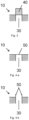
- the Fig. 2 to Fig. 4 three exemplary embodiments then show how the outlet of the gas channel 3.0 can be provided with a catalytic converter 40 according to the invention.
- Fig. 1 the battery module 10 is shown in simplified form in a cross section.
- the battery module has 4 accumulators, usually the number will be significantly higher.
- the accumulators are arranged in such a way that they have a connection to the gas channel 30 during thermal runaway. This means that the hot gases are removed quickly and safely.
- the battery module 10 can in particular according to DE 10 2019 216 606 A1 or the DE 10 2019 216 608 A1 be carried out.
- a catalyst 40 is arranged at the outlet of the gas channel 30 in order to convert the dangerous gases, for example and in particular carbon monoxide and hydrogen, in particular to burn them with atmospheric oxygen. Carbon monoxide becomes carbon dioxide and hydrogen becomes water.
- Fig. 2 consists Fig. 2 a and Fig. 2 b.
- Fig. 2 a shows a lateral cross section, Fig. 2 b a supervision.
- the catalyst 40 is designed as a platinum network at the outlet of the gas channel 30. The advantage is that it closes cleanly with the battery module 10 and itself only forms a small flow resistance, so that the hot gases escaping are not retained and other accumulators 20 cannot overheat.
- Fig. 3 Another exemplary second embodiment is shown.
- the catalyst 40 is designed as a wire cage or as wire wool.
- the outflowing gas causes additional ambient air to be sucked in from the side, so that there is better mixing between ambient air and outflowing gases in the area of the catalytic converter 40, which increases ignition reliability and promotes conversion on the catalytic converter 40.
- the disadvantage is that the catalytic converter 40 rises above the surface of the battery module 10.
- Fig. 4 consists Fig. 4 a and Fig. 4 b.
- Fig. 4 shows a third exemplary embodiment with a Best membrane 50.
- the bursting membrane 50 is, for example, a thin plastic film, for example on polyethylene, polypropylene or polytetrafluoroethylene.
- the bursting membrane 50 is coated with a catalyst layer on the side facing the gas channel 30, for example vapor-coated with platinum. Such layers can be extremely thin and therefore save material.
- the bursting membrane 50 tears open and the dangerous gases come into contact with atmospheric oxygen and the catalyst 40.
- the advantage of this embodiment is that the catalytic converter 40 is not exposed to the environment during normal operation, so it cannot be covered by dust, for example. This ensures that the catalyst can be used in an emergency.
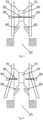
- Fig. 5 shows this in regular operation and Fig. 6 after triggering after a thermal runaway.
- the gas channel 30 has air supply lines 60 which are arranged under the catalytic converter 40.
- the air supply lines 60 are closed by the closure element 70.
- a holding element which consists of a melting element 80 and two clamping elements 90. If a thermal runaway occurs, the gases mix with the air in the gas channel 30, so that initially a certain small conversion of this gas mixture on the catalyst 40 causes a temperature increase, so that the melting element 80 melts.
- the closure element 70 jumps into its relaxed state, as shown in Fig. 6 is shown.
- the narrowing causes the Venturi effect to increase the flow speed, which promotes better mixing, and the Bernoulli effect to reduce the pressure, so that the ambient air is sucked in.
Landscapes
- Chemical & Material Sciences (AREA)
- Chemical Kinetics & Catalysis (AREA)
- Electrochemistry (AREA)
- General Chemical & Material Sciences (AREA)
- Battery Mounting, Suspending (AREA)
Abstract
Description
- Die Erfindung betrifft ein Batteriemodul insbesondere für Akkumulatoren auf Lithium-Basis.
- Akkumulatoren auf Lithium-Basis sind zunehmend interessant, beispielsweise aufgrund der hohen Energiedichte. Gerade für große Energiespeicher gibt es jedoch zwei grundlegende Unterschiede beispielsweise zum Blei-Schwefelsäure-Akkumulator. Zum einen können die einzelnen Zellen nicht einfach beliebig vergrößert werden. Dieses führt dazu, dass regelmäßig eine Vielzahl von Akkumulatoren zu einem größeren Modul zusammengestellt wird. Zum anderen ist gerade bei diesen Akkumulatoren das Problem des thermischen Durchgehens gegeben. Da hierbei auch eine große Menge an Gas entsteht, bedeutet dieses ein großes Risiko, insbesondere in kritischen Umgebungen, wie sich beispielsweise an Akkumulatoren in Luftfahrzeugen gezeigt hat.
- Daher werden entsprechende Akkumulatoren, beispielsweise für den Einsatz in Unterseebooten in spezielle Module integriert, die einen hohen Schutz bieten, wenn ein thermisches Durchgehen bei einem einzelnen Akkumulator erfolgt. Dadurch wird das kaskadenartige Durchgehen benachbarter Akkumulatoren verhindert und die Sicherheit bleibt gewährleistet.
- Aus der
DE 10 2019 216 606 A1 ist ein Batteriemodul bekannt, wobei das zweite Modulgehäuseteil wenigstens einen ersten Gaskanal aufweist, wobei der erste Gaskanal wenigsten die Berststelle des zweiten Modulgehäuseteils, welche hinter dem ersten Akkumulator angeordnet ist, und die Berststelle des zweiten Modulgehäuseteils, welche hinter dem zweiten Akkumulator angeordnet ist auf der den Hohlräumen gegenüberliegenden Seite miteinander verbindet. - Aus der
DE 10 2019 216 608 A1 ist ein Batteriemodul bekannt, wobei das Batteriemodul wenigstens einen ersten Akkumulator und einen zweiten Akkumulator aufweist, wobei alle Akkumulatoren wenigstens zwei elektrische Kontakte aufweisen, wobei alle Akkumulatoren eine Berstmembran aufweisen, wobei alle Berstmembranen in die gleiche Richtung angeordnet sind, wobei alle Akkumulatoren in einem Modulgehäuse angeordnet sind, wobei wenigstens ein erster Sensor in Wirkrichtung hinter der Berstmembran der Akkumulatoren angeordnet ist, wobei der erste Sensor zur Erfassung von Druck, Temperatur oder einer chemischen Substanz ausgebildet ist. - Mit diesen Modulen kann zwar eine Kettenreaktion bei einem thermischen Durchgehen eines einzelnen Akkumulators verhindert werden, die dabei entstehenden Gase können jedoch nicht verhindert werden. Da aufgrund der gegenüber dem Blei-Säure-Akkumulator eine wesentlich größere Anzahl an Akkumulatoren benötigt wird und immer von einer Fertigungstoleranz auszugehen ist, ist es schwierig eine absolute Sicherheit zu geben, dass es bei keinem der Akkumulatoren zu einem thermischen Durchgehen kommt. Für den Einsatz insbesondere in einem Unterseeboot ist es aber wünschenswert, gefährliche Gase zu vermeiden, um eine Gefährdung für die Besatzung zu reduzieren, auch wenn es bei einem einzelnen Akkumulator zu einem thermischen Durchgehen kommt.
- Aus der
DE 10 2014 212 173 A1 ist eine Gasreinigungseinheit für eine Lithium-Zelle bekannt. - Aus der
US 2021 / 0 135 314 A1 ist ein Gehäuse für eine elektrochemische Zelle bekannt. - Aus der
KR 10 2 251 413 B1 - Aus der
DE 10 2012 222 870 A1 ist ein Energiespeicher mit einem Sicherheitsventil bekannt. - Aufgabe der Erfindung ist es, ein Batteriemodul zu schaffen, welches die Abgabe gefährlicher Gase für die Besatzung beim thermischen Durchgehen eines Akkumulators verhindert.
- Gelöst wird diese Aufgabe durch das Batteriemodul mit den in Anspruch 1 angegebenen Merkmalen. Vorteilhafte Weiterbildungen ergeben sich aus den Unteransprüchen, der nachfolgenden Beschreibung sowie den Zeichnungen.
- Das erfindungsgemäße Batteriemodul weist eine Mehrzahl an Akkumulatoren auf. Das Batteriemodul weist einen Gaskanal auf. Der Gaskanal weist einen Auslass auf. Am Ausgang des Gaskanals ist ein Katalysator angeordnet. Die Anordnung am Ausgang stellt sicher, dass neben dem Gas aus dem thermischen Durchgehen eines Akkumulators auch Luftsauerstoff vorhanden ist, mit dem die gefährlichen Gase, beispielsweise und insbesondere Kohlenmonoxid und Wasserstoff zu Kohlendioxid und Wasser und somit ungefährlichen Verbindungen umgesetzt werden können.
- Um eine gute Umsetzung am Katalysator zu erreichen ist eine gezielte Zufuhr von Umgebungsluft in dem den Katalysator strömenden Gasstrom sinnvoll, um ausreichend Sauerstoff für eine Umsetzung zu haben. Die Herausforderung hierbei ist, dass ein Katalysator, wenn er permanent mit der Umgebungsluft in Kontakt steht. Beispielsweise und insbesondere in einem Unterseeboot kann dann der Katalysator beispielsweise von öligen Substanzen bedeckt werden und so seine Aktivität verlieren. Daher ist es notwendig, den Katalysator im Schadensfall eines Akkumulators mit Luft zu versorgen, im Regelbetrieb des Akkumulators beziehungsweise Batteriemoduls aber vor Kontamination zu schützen. Um die Sauerstoffzufuhr sicher zu stellen, weist der Gaskanal vor dem Katalysator wenigstens eine erste Luftzuführung auf. Um aber im Regelbetrieb den Katalysator zu schützen, weist die erste Luftzuführung ein Verschlusselement auf. Dadurch ist die erste Luftzuführung im Regelbetrieb verschlossen und so der Katalysator vor Kontamination geschützt. Das Verschlusselement wird durch ein Halteelement in einer die erste Luftzuführung verschließenden Position gehalten. Beim Entfernen des Halteelements kann das Verschlusselement beispielsweise wegklappen, runterfallen oder in sonst einer Weise von der ersten Luftzuführung entfernt werden, beispielsweise durch ein vorgespanntes Federelement. Das Halteelement weist ein Schmelzelement auf. Das Schmelzelement des Halteelements ist innerhalb des Katalysators angeordnet.
- Der Effekt ist, dass die ersten Gase mit dem im Gaskanal vorhandenen Sauerstoff am Katalysator eine erste Umsetzung und damit verbunden eine erste Wärmefreisetzung bewirken. Diese Wärmeentwicklung wird genutzt, um das Schmelzelement zu schmelzen, sodass das Halteelement das Verschlusselement nicht mehr in Position hält. Dadurch wird die erste Luftzuführung freigegeben, wodurch Umgebungsluft dem den Katalysator zugeführten Gasstrom zugeführt wird, sodass eine sichere Umsetzung der schädlichen Gase am Katalysator erfolgt.
- Das Batteriemodul kann einen beliebigen Aufbau aufweisen. Bevorzugt ist das Batteriemodul entsprechend der
DE 10 2019 216 606 A1 oder derDE 10 2019 216 608 A1 die hiermit vollumfänglich für den Aufbau des Batteriemoduls mit in die Offenbarung aufgenommen werden. - Insbesondere ist das Batteriemodul für den Einsatz in einem Unterseeboot geeignet. In einem Unterseeboot gibt es nur eine sehr begrenzte umgebende Atmosphäre und diese wird zusätzlich von der Besatzung benötigt. Daher ist die Sicherheit für den Einsatz an Bord eines Unterseebootes von besonderer Bedeutung.
- Beispielsweise und bevorzugt weist das Batteriemodul wenigstens einen ersten Akkumulator und einen zweiten Akkumulator auf. Bevorzugt weist das Batteriemodul 20 bis 500, besonders bevorzugt 50 bis 200, Akkumulatoren auf. Alle Akkumulatoren weisen eine zylindrische Bauform auf. Das bedeutet, die einzelnen Akkumulatoren sind nicht als Pouch-Zellen ausgeführt, die üblicherweise eine größere Volumenveränderung kompensieren können. Dafür können Akkumulatoren in zylindrischer Form leicht hergestellt und auch in großer Anzahl zu einem Modul verbunden werden. Alle Akkumulatoren weisen wenigstens zwei elektrische Kontakte auf, bevorzugt genau zwei, einen für die Anode und einen für die Kathode. Alle Akkumulatoren weisen auf einer ersten Zylinderstirnfläche wenigstens einen elektrischen Kontakt auf. Beispielsweise kann der andere elektrische Kontakt über die Mantelfläche kontaktiert werden. Weiter weisen alle Akkumulatoren auf einer zweiten Zylinderstirnfläche eine Berstmembran auf.
- Im Batteriemodul sind alle Akkumulatoren beispielsweise und bevorzugt parallel zueinander angeordnet, wobei alle ersten Zylinderstirnflächen in die gleiche Richtung angeordnet sind. Hierdurch kann die elektrische Energie zentral auf einer Seite abgeführt werden. Alle Akkumulatoren sind in einem Modulgehäuse angeordnet.
- Das Modulgehäuse weist beispielsweise und bevorzugt ein erstes Modulgehäuseteil und ein zweites Modulgehäuseteil auf. Das erste Modulgehäuseteil ist flächig ausgeführt und senkrecht zur Längsrichtung der Akkumulatoren angeordnet. Auch das zweite Modulgehäuseteil ist flächig ausgeführt und senkrecht zur Längsrichtung der Akkumulatoren angeordnet.
- Das erste Modulgehäuseteil weist beispielsweise und bevorzugt erste Ausnehmungen zur Aufnahme jeweils eines Teils der Akkumulatoren im Bereich der ersten Zylinderstirnflächen auf. Das erste Modulgehäuseteil weist im Bereich der ersten Ausnehmungen Öffnungen zur Durchführung der elektrischen Verbindungen auf. Dieses ist notwendig, um die Akkumulatoren elektrisch kontaktieren und die Leistung abführen zu können. Das zweite Modulgehäuseteil weist zweite Ausnehmungen zur Aufnahme jeweils eines Teils der Akkumulatoren im Bereich der zweiten Zylinderstirnflächen auf.
- Beispielsweise und bevorzugt ist zwischen dem ersten Modulgehäuseteil, den zweiten Modulgehäuseteil und den Akkumulatoren eine Vergussmasse angeordnet.
- Das zweite Modulgehäuseteil weist beispielsweise und bevorzugt im Bereich der zweiten Ausnehmungen Berststellen auf. Zwischen den Berststellen des zweiten Modulgehäuseteils und den Berstmembranen der zweiten Zylinderstirnflächen ist jeweils ein Hohlraum angeordnet. Der Hohlraum kann beispielsweise und bevorzugt gasgefüllt, insbesondere luftgefüllt oder Schutzgas-gefüllt, insbesondere mit Stickstoff oder Argon gefüllt, sein.
- Durch die Anordnung aller Akkumulatoren in dem Modulgehäuse sind alle Akkumulatoren gegenüber der Umgebung geschützt. Kommt es nun zum thermischen Durchgehen eines Akkumulators, so produziert dieser großen Mengen heißer Gase, welche bei direkten Kontakt leicht dazu führen können, dass benachbarte Akkumulatoren ebenfalls kritisch werden und selber thermischen durchgehen. Da die Akkumulatoren jedoch innerhalb des Modulgehäuses geschützt sind, kann ein einzelner durchgehender Akkumulator nicht benachbarte Akkumulatoren ebenfalls kritisch werden lassen. Ein einfaches und vollständiges Einbauen würde jedoch dazu führen, dass der entstehende Druck nicht abgeführt werden kann. Kommt es bei einem einzelnen Akkumulator nun zu einem thermischen Durchgehen, so entsteht im Inneren des Akkumulators ein Druck dieser lässt die Berstmembran an der zweiten Zylinderstirnfläche bersten. Hierdurch steigt der Druck im Hohlraum, welcher zu dem Akkumulator benachbart ist . Dieser Druckanstieg führt dazu, dass auch die Berststelle im Bereich der zweiten Ausnehmungen des zweiten Modulgehäuse Teils birst, sodass die entstehenden Gase nach außen abgeführt werden und der Druck abgebaut wird, ohne dass weiterer Schaden erzeugt wird.
- Beispielsweise und bevorzugt weist das zweite Modulgehäuseteil wenigstens einen ersten Gaskanal auf, wobei der erste Gaskanal wenigsten die Berststelle des zweiten Modulgehäuseteils, welche hinter dem ersten Akkumulator angeordnet ist, und die Berststelle des zweiten Modulgehäuseteils, welche hinter dem zweiten Akkumulator angeordnet ist auf der den Hohlräumen gegenüberliegenden Seite miteinander verbindet. Durch den ersten Gaskanal können somit Gase, welche bei einem thermischen Durchgehen oder anderer exothermen chemischen Reaktion eines Akkumulators entstehen, gezielt abgeführt werden, beispielsweise nach oben abgeführt werden. Dieses ist besonders bevorzugt, wenn mehrere Batteriemodule nebeneinander aufgestellt werden sollen, damit die entstehenden Gase nicht mit den elektrischen Kontakten eines anderen Batteriemoduls in Kontakt kommen, da sie diese beschädigen könnten.
- In einer weiteren Ausführungsform der Erfindung weist der Gaskanal im Bereich des Katalysators einen verjüngten Querschnitt auf. Hierdurch wird die Strömungsgeschwindigkeit erhöht, was wiederum aufgrund des Bernoulli-Effekts zu einem niedrigeren Druck und damit einem Ansaugen von Umgebungsluft führt. Außerdem führt die aufgrund des Venturi-Effekts höhere Strömungsgeschwindigkeit zu einer turbulenteren Strömung, was eine bessere Durchmischung zur Folge hat.
- In einer weiteren Ausführungsform der Erfindung ist das Verschlusselement hülsenförmig um den Gaskanal angeordnet. Besonders bevorzugt weist das Verschlusselement zwei Schlitze in Längsrichtung auf und nimmt im entspannten Zustand eine V-förmige Form ein, wie dieses beispielsweise bei einem Dübel der Fall ist, der im Auslieferungszustand durch einen Kontakt an der Spitze zusammengehalten wird. Der Kontakt bricht bei ersten Eindrehen der Schraube und die Flügel des Dübels biegen sich nach außen. Damit kann auf weitere Elemente, wie beispielsweise ein unter dem Verschlusselement angeordnetes Federelement verzichtet werden.
- In einer weiteren Ausführungsform der Erfindung besteht das Schmelzelement aus einem Elastomer, beispielsweise Polyethylen, Polypropylen, Polystryrol, Polymethylmethacrylat, Polyamid oder Polyoxymethylen. Hierbei ist ein geringer Schmelzpunkt und eine geringe Schmelzenthalpie (beziehungsweise niedrige Glasübergangstemperatur) zielführend, also insbesondere Polymere mit niedriger oder mittlerer Kettenlänge und möglichst geringer Verzweigung. Beispielsweise kann ein PE mit 10.000 Dalton und einer Kristallinität von 50 % verwendet werden.
- In einer weiteren Ausführungsform der Erfindung enthält der Katalysator Platin. Platin ist auf der einen Seite besonders gut geeignet, um Wasserstoff katalytisch zu entzünden. Ebenso kann Kohlenmonoxid an Platin gut umgesetzt werden. Es muss jedoch eben nicht das gesamte gefährliche Gas am Katalysator umgesetzt werden. Es kann bereits ausreichen, dass durch eine Umsetzung am Katalysator Wärme oder eine Flamme erzeugt, in der dann die gefährlichen Gase zu wenigstens weniger gefährlichen oder ungefährlichen Produkten abbrennen können.
- In einer weiteren Ausführungsform der Erfindung ist der Katalysator als Gitter oder Netz ausgeführt. Die Gase können somit sehr gut aus dem Gaskanal ausströmen und durch das Gitter oder Netz strömen, sich in dieser Struktur mit Luftsauerstoff vermischen und abreagieren. Das Gitter kann dabei ein Kunststoff- oder Metallgitter sein, das mit dem Katalysator beschichtet ist oder das Gitter kann aus dem Katalysator bestehen.
- In einer weiteren Ausführungsform der Erfindung ist der Gaskanal am Auslass mit einer Berstmembran versehen. Die Berstmembarn ist auf der dem Gaskanal zugewandten Seite mit dem Katalysator beschichtet. Dadurch ist der Katalysator im Regelbetrieb sehr gut vor Alterung oder Verschmutzung geschützt. Das weiteren kann beispielsweise eine Berstmembran aus einer Kunststofffolie extrem dünn mit beispielsweise einer Platinschicht bedampft werden, was wiederum den Edelmetallbedarf und damit die Kosten senkt. Da nur eine Initialzündung am Katalysator erfolgen muss, reicht diese geringe Menge Katalysator in der Beschichtung aus.
- In einer weiteren Ausführungsform der Erfindung grenzt der Katalysator nur einseitig an den Gaskanal an. Dadurch grenzt der Katalysator mit allen anderen Seiten an die Umgebungsluft, was eine Vermischung mit dem Luftsauerstoff verbessert und so zu einer stabilen Umsetzung der gefährlichen Gase führt. Beispielsweise kann der Katalysator eine drahtschwammartige Struktur aufweisen.
- In einem weiteren Aspekt betrifft die Erfindung ein Verfahren zur Umsetzung gefährlicher Gase aus einem thermischen Durchgehen eines Akkumulators. Bevorzugt wird das Verfahren mit einem erfindungsgemäßen Batteriemodul durchgeführt. Die Gase werden zunächst von dem Akkumulator, welcher thermisch durchgegangen ist, durch einen Gaskanal geführt. Dadurch werden die heißen Gase von den anderen Akkumulatoren des Batteriemoduls weggeführt und damit das thermische Durchgehen weitere Akkumulatoren weniger wahrscheinlich. Das Gas wird im Bereich des Ausgangs des Gaskanals in Anwesenheit eines Katalysators mit Umgebungsluft vermischt und umgesetzt.
- Dadurch gelangen keine gefährlichen Gase mehr in die Umgebung, insbesondere die Hauptbestandteile Kohlenmonoxid und Wasserstoff werden zuverlässig zu Kohlendioxid und Wasser umgesetzt.
- Nachfolgend ist das erfindungsgemäße Batteriemodul anhand eines in den Zeichnungen dargestellten Ausführungsbeispiels näher erläutert.
- Fig. 1
- Modul
- Fig. 2
- erste Ausführungsform
- Fig. 3
- zweite Ausführungsform
- Fig. 4
- dritte Ausführungsform
- Fig. 5
- viertes Ausführungsform vor der Auslösung
- Fig. 6
- viertes Ausführungsform nach der Auslösung
-
Fig. 1 zeigt einen Überblick des Batteriemoduls 10. DieFig. 2 bis Fig. 4 zeigen dann drei beispielhafte Ausführungsformen, wie der Ausgang des Gaskanals 3,0 erfindungsgemäß mit einem Katalysator 40 versehen sein kann. - In
Fig. 1 ist das Batteriemodul 10 vereinfacht in einem Querschnitt gezeigt. Im dargestellten Fall weist das Batteriemodul 4 Akkumulatoren auf, üblicherweise wird die Zahl deutlich höher liegen. Die Akkumulatoren sind so angeordnet, dass diese beim thermischen Durchgehen eine Verbindung zu Gaskanal 30 aufweisen. Dadurch werden die heißen Gase schnell und sicher abgeführt. Das Batteriemodul 10 kann insbesondere entsprechend derDE 10 2019 216 606 A1 oder derDE 10 2019 216 608 A1 ausgeführt sein. Neu hinzu kommt, dass am Auslass des Gaskanals 30 ein Katalysator 40 angeordnet ist, um die gefährlichen Gase, beispielweise und insbesondere Kohlenmonoxid und Wasserstoff umzusetzen, insbesondere mit Luftsauerstoff zu verbrennen. Aus Kohlenmonoxid wird Kohlendioxid, aus Wasserstoff Wasser. - Im Folgenden sind drei beispielhafte Ausführungsformen zur Anordnung des Katalysators 40 am Auslass des Gaskanals 30 gezeigt.
-
Fig. 2 besteht ausFig. 2 a undFig. 2 b.Fig. 2 a zeigt einen seitlichen Querschnitt,Fig. 2 b eine Aufsicht. Der Katalysator 40 ist in dieser ersten Ausführungsform als ein Platin-Netz am Auslass des Gaskanals 30 ausgebildet. Vorteil ist, dass dieser sauber mit dem Batteriemodul 10 abschließt und selber nur einen geringen Strömungswiderstand bildet, die heiß austretenden Gase somit nicht zurückgehalten werden und nicht weitere Akkumulatoren 20 überhitzen können. - In
Fig. 3 ist eine weitere beispielhafte zweite Ausführungsform gezeigt. Der Katalysator 40 ist als Drahtkäfig oder als Drahtwolle ausgebildet. Durch das ausströmende Gas wird von der Seite zusätzliche Umgebungsluft eingesogen, sodass es bereits im Bereich des Katalysators 40 zu einer besseren Vermischung zwischen Umgebungsluft und ausströmenden Gasen kommt, was die Zündzuverlässigkeit erhöht und eine Umsetzung am Katalysator 40 fördert. Nachteilig ist, dass der Katalysator 40 sich dadurch über die Oberfläche des Batteriemoduls 10 erhebt. -
Fig. 4 besteht ausFig. 4 a undFig. 4 b.Fig. 4 zeigt eine dritte beispielhafte Ausführungsform mit einer Bestmembran 50. InFig. 4 a ist diese im Normalzustand geschlossen dargestellt, inFig. 4 b geöffnet nach dem thermischen Durchgehen eines Akkumulators 20. Die Berstmembran 50 ist beispielsweise eine dünne Kunststofffolie, beispielsweise auf Polyethylen, Polypropylen oder Polytetrafluorethylen. Die Berstmembran 50 ist auf der zum Gaskanal 30 gerichteten Seite mit einer Katalysatorschicht beschichtet, beispielweise mit Platin bedampft. Solche Schichten können extrem dünn und damit materialsparend sein. Bei einem thermischen Durchgehen reißt die Berstmembran 50 auf und die gefährlichen Gase kommen mit Luftsauerstoff und dem Katalysator 40 in Kontakt. Vorteil dieser Ausführungsform ist, dass der Katalysator 40 im Normalbetrieb nicht der Umgebung ausgesetzt ist, also nicht beispielweise von Staub bedeckt werden kann. Somit ist im Ernstfall die Einsatzfähigkeit des Katalysators gewährleistet. - In
Fig. 5 und Fig. 6 ist eine vierte Ausführungsform gezeigt.Fig. 5 zeigt diese im Regelbetrieb undFig. 6 nach dem Auslösen nach einem Thermal Runaway. Der Gaskanal 30 weist Luftzuführungen 60 auf, die unter dem Katalysator 40 angeordnet sind. Im Normalzustand, wie inFig. 5 gezeigt, werden die Luftzuführungen 60 durch das Verschlusselement 70 verschlossen. Dieses geschieht durch ein Halteelement, welches aus einem Schmelzelement 80 und zwei Spannelementen 90 besteht. Kommt es zu einem Thermal Runaway, so vermischen sich die Gase mit der Luft im Gaskanal 30, sodass am Anfang eine gewisse kleine Umsetzung dieses Gasgemisches am Katalysator 40 zu einer Temperaturerhöhung kommt, sodass das Schmelzelement 80 schmilzt. Dadurch springt das Verschlusselement 70 in seinen entspannten Zustand, wie dieser inFig. 6 dargestellt ist. Dadurch werden die Luftzuführungen 60 freigegeben, sodass Luft angesaugt werden kann. Dieses wird durch die Verengung des Gaskanals 30 verbessert. Durch die Verengung kommt es durch den Venturi-Effekt zu einer Erhöhung der Strömungsgeschwindigkeit, die eine bessere Vermischung fördert und durch den Bernoulli-Effekt zu einer Druckerniedrigung, sodass die Umgebungsluft eingesogen wird. -
- 10
- Batteriemodul
- 20
- Akkumulator
- 30
- Gaskanal
- 40
- Katalysator
- 50
- Berstmembran
- 60
- Luftzuführung
- 70
- Verschlusselement
- 80
- Schmelzelement
- 90
- Spannelement
Claims (10)
- Batteriemodul (10), wobei das Batteriemodul (10) eine Mehrzahl an Akkumulatoren (20) aufweist, wobei das Batteriemodul (10) einen Gaskanal (30) aufweist, wobei der Gaskanal (30) einen Auslass aufweist, dadurch gekennzeichnet, dass am Ausgang des Gaskanals ein Katalysator (40) angeordnet ist, wobei der Gaskanal (30) vor dem Katalysator (40) wenigstens eine erste Luftzuführung (60) aufweist, wobei die erste Luftzuführung (60) ein Verschlusselement (70) aufweist, wobei das Verschlusselement (70) durch ein Halteelement in einer die erste Luftzuführung (60) verschließenden Position gehalten wird, wobei das Halteelement ein Schmelzelement (80) aufweist, wobei das Schmelzelement (80) des Halteelements innerhalb des Katalysators (40) angeordnet ist.
- Batteriemodul (10) nach Anspruch 1, dadurch gekennzeichnet, dass der Gaskanal (30) im Bereich des Katalysators (40) einen verjüngten Querschnitt aufweist.
- Batteriemodul (10) nach einem der vorstehenden Ansprüche, dadurch gekennzeichnet, dass das Verschlusselement (70) hülsenförmig um den Gaskanal (30) angeordnet ist.
- Batteriemodul (10) nach Anspruch 3, dadurch gekennzeichnet, dass das Verschlusselement (70) zwei Schlitze in Längsrichtung aufweist und im entspannten Zustand eine V-förmige Form einnimmt.
- Batteriemodul (10) nach einem der vorstehenden Ansprüche, dadurch gekennzeichnet, dass das Schmelzelement (80) aus einem Elastomer besteht.
- Batteriemodul (10) nach einem der vorstehenden Ansprüche, dadurch gekennzeichnet, dass der Katalysator (40) Platin enthält.
- Batteriemodul (10) nach einem der vorstehenden Ansprüche, dadurch gekennzeichnet, dass der Katalysator (40) als Gitter oder Netz ausgeführt ist.
- Batteriemodul (10) nach einem der vorstehenden Ansprüche, dadurch gekennzeichnet, dass der Gaskanal (30) am Auslass mit einer Berstmembran (50) versehen ist, wobei die Berstmembarn (50) auf der dem Gaskanal (30) zugewandten Seite mit dem Katalysator (40) beschichtet ist.
- Batteriemodul (10) nach einem der vorstehenden Ansprüche, dadurch gekennzeichnet, dass der Katalysator (40) nur einseitig an den Gaskanal (30) angrenzt.
- Verfahren zur Umsetzung gefährlicher Gase aus einem thermischen Durchgehen eines Akkumulators (20), wobei die Gase zunächst durch einen Gaskanal (30) geführt werden, wobei das Gas am Ausgang des Ganskanals in Anwesenheit eines Katalysators (40) mit Umgebungsluft vermischt und umgesetzt wird.
Applications Claiming Priority (1)
| Application Number | Priority Date | Filing Date | Title |
|---|---|---|---|
| DE102022209586 | 2022-09-13 |
Publications (2)
| Publication Number | Publication Date |
|---|---|
| EP4340113A1 true EP4340113A1 (de) | 2024-03-20 |
| EP4340113B1 EP4340113B1 (de) | 2025-02-26 |
Family
ID=88018151
Family Applications (1)
| Application Number | Title | Priority Date | Filing Date |
|---|---|---|---|
| EP23196743.1A Active EP4340113B1 (de) | 2022-09-13 | 2023-09-12 | Batteriemodul |
Country Status (1)
| Country | Link |
|---|---|
| EP (1) | EP4340113B1 (de) |
Cited By (5)
| Publication number | Priority date | Publication date | Assignee | Title |
|---|---|---|---|---|
| DE102024118306B3 (de) * | 2024-06-28 | 2025-09-25 | Thyssenkrupp Ag | Verfahren zum Betreiben eines Energiespeichers in einem Unterseeboot ohne aktive Kühlung |
| DE102024135243A1 (de) * | 2024-06-28 | 2025-12-31 | Thyssenkrupp Ag | Bereitstellung einer kurzfristigen Leistungsreserve in einem Unterseeboot |
| DE102024118305A1 (de) * | 2024-06-28 | 2025-12-31 | Thyssenkrupp Ag | Verfahren zum Betreiben einer Mehrzahl von Energiespeichern an einem Bordnetz in einem Unterseeboot |
| WO2026002715A1 (de) | 2024-06-28 | 2026-01-02 | Tkms Gmbh | Bereitstellung einer kurzfristigen leistungsreserve in einem unterseeboot |
| WO2026002704A1 (de) | 2024-06-28 | 2026-01-02 | Tkms Gmbh | Hot-standby für batteriesysteme |
Citations (8)
| Publication number | Priority date | Publication date | Assignee | Title |
|---|---|---|---|---|
| DE102012222870A1 (de) | 2012-12-12 | 2014-06-26 | Robert Bosch Gmbh | Energiespeicher mit Sicherheitsventil |
| DE102014212173A1 (de) | 2014-06-25 | 2016-01-14 | Robert Bosch Gmbh | Gasreinigungseinheit für Lithium-Zelle |
| DE102019216606A1 (de) | 2019-10-29 | 2021-04-29 | Thyssenkrupp Ag | Batteriemodul |
| DE102019216608A1 (de) | 2019-10-29 | 2021-04-29 | Thyssenkrupp Ag | Batteriemodul mit Überwachung des thermischen Durchgehens von einzelnen Zellen |
| US20210135314A1 (en) | 2017-06-29 | 2021-05-06 | Sargent Manufacturing Company | Electrochemical cell housing |
| KR102251413B1 (ko) | 2020-12-31 | 2021-05-13 | (주)세라컴 | 에너지저장시스템 |
| DE102021130696A1 (de) * | 2021-02-26 | 2022-09-01 | GM Global Technology Operations LLC | Batterieausgasungs-filtersystem und verfahren zum filtern von ausgasungen aus einer batteriezelle |
| WO2023147501A2 (en) * | 2022-01-27 | 2023-08-03 | Altect, Inc. | Passive automatic injector reactor system |
-
2023
- 2023-09-12 EP EP23196743.1A patent/EP4340113B1/de active Active
Patent Citations (8)
| Publication number | Priority date | Publication date | Assignee | Title |
|---|---|---|---|---|
| DE102012222870A1 (de) | 2012-12-12 | 2014-06-26 | Robert Bosch Gmbh | Energiespeicher mit Sicherheitsventil |
| DE102014212173A1 (de) | 2014-06-25 | 2016-01-14 | Robert Bosch Gmbh | Gasreinigungseinheit für Lithium-Zelle |
| US20210135314A1 (en) | 2017-06-29 | 2021-05-06 | Sargent Manufacturing Company | Electrochemical cell housing |
| DE102019216606A1 (de) | 2019-10-29 | 2021-04-29 | Thyssenkrupp Ag | Batteriemodul |
| DE102019216608A1 (de) | 2019-10-29 | 2021-04-29 | Thyssenkrupp Ag | Batteriemodul mit Überwachung des thermischen Durchgehens von einzelnen Zellen |
| KR102251413B1 (ko) | 2020-12-31 | 2021-05-13 | (주)세라컴 | 에너지저장시스템 |
| DE102021130696A1 (de) * | 2021-02-26 | 2022-09-01 | GM Global Technology Operations LLC | Batterieausgasungs-filtersystem und verfahren zum filtern von ausgasungen aus einer batteriezelle |
| WO2023147501A2 (en) * | 2022-01-27 | 2023-08-03 | Altect, Inc. | Passive automatic injector reactor system |
Cited By (7)
| Publication number | Priority date | Publication date | Assignee | Title |
|---|---|---|---|---|
| DE102024118306B3 (de) * | 2024-06-28 | 2025-09-25 | Thyssenkrupp Ag | Verfahren zum Betreiben eines Energiespeichers in einem Unterseeboot ohne aktive Kühlung |
| EP4672534A1 (de) | 2024-06-28 | 2025-12-31 | TKMS GmbH | Verfahren zum betreiben eines energiespeichers in einem unterseeboot ohne aktive kühlung |
| DE102024135243A1 (de) * | 2024-06-28 | 2025-12-31 | Thyssenkrupp Ag | Bereitstellung einer kurzfristigen Leistungsreserve in einem Unterseeboot |
| DE102024118305A1 (de) * | 2024-06-28 | 2025-12-31 | Thyssenkrupp Ag | Verfahren zum Betreiben einer Mehrzahl von Energiespeichern an einem Bordnetz in einem Unterseeboot |
| WO2026002739A1 (de) | 2024-06-28 | 2026-01-02 | Tkms Gmbh | Verfahren zum betreiben einer mehrzahl von energiespeichern an einem bordnetz in einem unterseeboot |
| WO2026002715A1 (de) | 2024-06-28 | 2026-01-02 | Tkms Gmbh | Bereitstellung einer kurzfristigen leistungsreserve in einem unterseeboot |
| WO2026002704A1 (de) | 2024-06-28 | 2026-01-02 | Tkms Gmbh | Hot-standby für batteriesysteme |
Also Published As
| Publication number | Publication date |
|---|---|
| EP4340113B1 (de) | 2025-02-26 |
Similar Documents
| Publication | Publication Date | Title |
|---|---|---|
| EP4340113B1 (de) | Batteriemodul | |
| DE102020128756A1 (de) | Batterie mit einem Schutzelement und Kraftfahrzeug | |
| DE4443945C1 (de) | PEM-Brennstoffzelle | |
| DE69109336T2 (de) | Festoxidbrennstoffzelle. | |
| EP0923707A1 (de) | Katalysatorsystem und rekombinationseinrichtung zur rekombination von wasserstoff und sauerstoff, insbesondere für ein kernkraftwerk | |
| DE102019216608A1 (de) | Batteriemodul mit Überwachung des thermischen Durchgehens von einzelnen Zellen | |
| DE102013216071A1 (de) | Galvanisches System umfassend eine Mehrzahl von galvanischen Zellen und eine Entgasungseinrichtung | |
| DE2838857A1 (de) | Metalloxid/lanthannickelhydrid- akkumulator | |
| DE112009000073T5 (de) | Batterie und Batteriesystem | |
| EP1166278A1 (de) | Rekombinationseinrichtung und verfahren zur katalytischen rekombination von wasserstoff und/oder kohlenmonoxid mit sauerstoff in einem gasgemisch | |
| DE102019216606A1 (de) | Batteriemodul | |
| EP2920062A1 (de) | Boot mit elektroantrieb | |
| DE102014012568B4 (de) | Akkumulatorvorrichtung | |
| DE102018131092A1 (de) | Membranelektrodeneinrichtung | |
| DE102021005751A1 (de) | Batteriesystem | |
| DE112009000103B4 (de) | Strom erzeugende Zelle für eine Treibstoffbatterie | |
| DE102020120041A1 (de) | Batteriesystem und Kraftfahrzeug mit einem Batteriesystem | |
| EP1603661A2 (de) | Selbstheilende membran für eine brennstoffzelle | |
| DE102013223361A1 (de) | Batteriezelle mit Sicherheitsventil und semipermeablem Verschlusselement | |
| WO2025082691A1 (de) | Hochvoltbatterie als traktionsbatterie für ein kraftfahrzeug | |
| DE102021205891A1 (de) | Batterieeinheit | |
| DE102012222870A1 (de) | Energiespeicher mit Sicherheitsventil | |
| DE102021100727A1 (de) | Elektrischer Energiespeicher | |
| EP4371184A1 (de) | Abdeckung für ein batteriemodul oder für einen batteriespeicher | |
| DE102020216378B4 (de) | Hochvoltbatterie für ein elektrisch betriebenes Fahrzeug |
Legal Events
| Date | Code | Title | Description |
|---|---|---|---|
| PUAI | Public reference made under article 153(3) epc to a published international application that has entered the european phase |
Free format text: ORIGINAL CODE: 0009012 |
|
| STAA | Information on the status of an ep patent application or granted ep patent |
Free format text: STATUS: THE APPLICATION HAS BEEN PUBLISHED |
|
| AK | Designated contracting states |
Kind code of ref document: A1 Designated state(s): AL AT BE BG CH CY CZ DE DK EE ES FI FR GB GR HR HU IE IS IT LI LT LU LV MC ME MK MT NL NO PL PT RO RS SE SI SK SM TR |
|
| STAA | Information on the status of an ep patent application or granted ep patent |
Free format text: STATUS: REQUEST FOR EXAMINATION WAS MADE |
|
| 17P | Request for examination filed |
Effective date: 20240715 |
|
| RBV | Designated contracting states (corrected) |
Designated state(s): AL AT BE BG CH CY CZ DE DK EE ES FI FR GB GR HR HU IE IS IT LI LT LU LV MC ME MK MT NL NO PL PT RO RS SE SI SK SM TR |
|
| GRAP | Despatch of communication of intention to grant a patent |
Free format text: ORIGINAL CODE: EPIDOSNIGR1 |
|
| STAA | Information on the status of an ep patent application or granted ep patent |
Free format text: STATUS: GRANT OF PATENT IS INTENDED |
|
| INTG | Intention to grant announced |
Effective date: 20240927 |
|
| GRAS | Grant fee paid |
Free format text: ORIGINAL CODE: EPIDOSNIGR3 |
|
| GRAA | (expected) grant |
Free format text: ORIGINAL CODE: 0009210 |
|
| STAA | Information on the status of an ep patent application or granted ep patent |
Free format text: STATUS: THE PATENT HAS BEEN GRANTED |
|
| AK | Designated contracting states |
Kind code of ref document: B1 Designated state(s): AL AT BE BG CH CY CZ DE DK EE ES FI FR GB GR HR HU IE IS IT LI LT LU LV MC ME MK MT NL NO PL PT RO RS SE SI SK SM TR |
|
| REG | Reference to a national code |
Ref country code: GB Ref legal event code: FG4D Free format text: NOT ENGLISH |
|
| REG | Reference to a national code |
Ref country code: CH Ref legal event code: EP |
|
| REG | Reference to a national code |
Ref country code: DE Ref legal event code: R096 Ref document number: 502023000618 Country of ref document: DE |
|
| REG | Reference to a national code |
Ref country code: DE Ref legal event code: R084 Ref document number: 502023000618 Country of ref document: DE |
|
| REG | Reference to a national code |
Ref country code: IE Ref legal event code: FG4D Free format text: LANGUAGE OF EP DOCUMENT: GERMAN |
|
| REG | Reference to a national code |
Ref country code: NL Ref legal event code: MP Effective date: 20250226 |
|
| PG25 | Lapsed in a contracting state [announced via postgrant information from national office to epo] |
Ref country code: RS Free format text: LAPSE BECAUSE OF FAILURE TO SUBMIT A TRANSLATION OF THE DESCRIPTION OR TO PAY THE FEE WITHIN THE PRESCRIBED TIME-LIMIT Effective date: 20250526 |
|
| PG25 | Lapsed in a contracting state [announced via postgrant information from national office to epo] |
Ref country code: FI Free format text: LAPSE BECAUSE OF FAILURE TO SUBMIT A TRANSLATION OF THE DESCRIPTION OR TO PAY THE FEE WITHIN THE PRESCRIBED TIME-LIMIT Effective date: 20250226 |
|
| PG25 | Lapsed in a contracting state [announced via postgrant information from national office to epo] |
Ref country code: PL Free format text: LAPSE BECAUSE OF FAILURE TO SUBMIT A TRANSLATION OF THE DESCRIPTION OR TO PAY THE FEE WITHIN THE PRESCRIBED TIME-LIMIT Effective date: 20250226 |
|
| PG25 | Lapsed in a contracting state [announced via postgrant information from national office to epo] |
Ref country code: ES Free format text: LAPSE BECAUSE OF FAILURE TO SUBMIT A TRANSLATION OF THE DESCRIPTION OR TO PAY THE FEE WITHIN THE PRESCRIBED TIME-LIMIT Effective date: 20250226 |
|
| REG | Reference to a national code |
Ref country code: LT Ref legal event code: MG9D |
|
| PG25 | Lapsed in a contracting state [announced via postgrant information from national office to epo] |
Ref country code: NO Free format text: LAPSE BECAUSE OF FAILURE TO SUBMIT A TRANSLATION OF THE DESCRIPTION OR TO PAY THE FEE WITHIN THE PRESCRIBED TIME-LIMIT Effective date: 20250526 Ref country code: IS Free format text: LAPSE BECAUSE OF FAILURE TO SUBMIT A TRANSLATION OF THE DESCRIPTION OR TO PAY THE FEE WITHIN THE PRESCRIBED TIME-LIMIT Effective date: 20250626 |
|
| PG25 | Lapsed in a contracting state [announced via postgrant information from national office to epo] |
Ref country code: NL Free format text: LAPSE BECAUSE OF FAILURE TO SUBMIT A TRANSLATION OF THE DESCRIPTION OR TO PAY THE FEE WITHIN THE PRESCRIBED TIME-LIMIT Effective date: 20250226 |
|
| PG25 | Lapsed in a contracting state [announced via postgrant information from national office to epo] |
Ref country code: HR Free format text: LAPSE BECAUSE OF FAILURE TO SUBMIT A TRANSLATION OF THE DESCRIPTION OR TO PAY THE FEE WITHIN THE PRESCRIBED TIME-LIMIT Effective date: 20250226 |
|
| PG25 | Lapsed in a contracting state [announced via postgrant information from national office to epo] |
Ref country code: PT Free format text: LAPSE BECAUSE OF FAILURE TO SUBMIT A TRANSLATION OF THE DESCRIPTION OR TO PAY THE FEE WITHIN THE PRESCRIBED TIME-LIMIT Effective date: 20250626 Ref country code: LV Free format text: LAPSE BECAUSE OF FAILURE TO SUBMIT A TRANSLATION OF THE DESCRIPTION OR TO PAY THE FEE WITHIN THE PRESCRIBED TIME-LIMIT Effective date: 20250226 |
|
| PG25 | Lapsed in a contracting state [announced via postgrant information from national office to epo] |
Ref country code: GR Free format text: LAPSE BECAUSE OF FAILURE TO SUBMIT A TRANSLATION OF THE DESCRIPTION OR TO PAY THE FEE WITHIN THE PRESCRIBED TIME-LIMIT Effective date: 20250527 Ref country code: BG Free format text: LAPSE BECAUSE OF FAILURE TO SUBMIT A TRANSLATION OF THE DESCRIPTION OR TO PAY THE FEE WITHIN THE PRESCRIBED TIME-LIMIT Effective date: 20250226 |
|
| REG | Reference to a national code |
Ref country code: DE Ref legal event code: R081 Ref document number: 502023000618 Country of ref document: DE Owner name: THYSSENKRUPP AG, DE Free format text: FORMER OWNERS: THYSSENKRUPP AG, 45143 ESSEN, DE; THYSSENKRUPP MARINE SYSTEMS GMBH, 24143 KIEL, DE Ref country code: DE Ref legal event code: R081 Ref document number: 502023000618 Country of ref document: DE Owner name: TKMS GMBH, DE Free format text: FORMER OWNERS: THYSSENKRUPP AG, 45143 ESSEN, DE; THYSSENKRUPP MARINE SYSTEMS GMBH, 24143 KIEL, DE |
|
| PG25 | Lapsed in a contracting state [announced via postgrant information from national office to epo] |
Ref country code: SE Free format text: LAPSE BECAUSE OF FAILURE TO SUBMIT A TRANSLATION OF THE DESCRIPTION OR TO PAY THE FEE WITHIN THE PRESCRIBED TIME-LIMIT Effective date: 20250226 |
|
| PG25 | Lapsed in a contracting state [announced via postgrant information from national office to epo] |
Ref country code: SM Free format text: LAPSE BECAUSE OF FAILURE TO SUBMIT A TRANSLATION OF THE DESCRIPTION OR TO PAY THE FEE WITHIN THE PRESCRIBED TIME-LIMIT Effective date: 20250226 |
|
| PG25 | Lapsed in a contracting state [announced via postgrant information from national office to epo] |
Ref country code: DK Free format text: LAPSE BECAUSE OF FAILURE TO SUBMIT A TRANSLATION OF THE DESCRIPTION OR TO PAY THE FEE WITHIN THE PRESCRIBED TIME-LIMIT Effective date: 20250226 |
|
| PGFP | Annual fee paid to national office [announced via postgrant information from national office to epo] |
Ref country code: DE Payment date: 20250919 Year of fee payment: 3 |
|
| PG25 | Lapsed in a contracting state [announced via postgrant information from national office to epo] |
Ref country code: IT Free format text: LAPSE BECAUSE OF FAILURE TO SUBMIT A TRANSLATION OF THE DESCRIPTION OR TO PAY THE FEE WITHIN THE PRESCRIBED TIME-LIMIT Effective date: 20250226 |
|
| PGFP | Annual fee paid to national office [announced via postgrant information from national office to epo] |
Ref country code: AT Payment date: 20251020 Year of fee payment: 3 Ref country code: FR Payment date: 20250922 Year of fee payment: 3 |
|
| PG25 | Lapsed in a contracting state [announced via postgrant information from national office to epo] |
Ref country code: CZ Free format text: LAPSE BECAUSE OF FAILURE TO SUBMIT A TRANSLATION OF THE DESCRIPTION OR TO PAY THE FEE WITHIN THE PRESCRIBED TIME-LIMIT Effective date: 20250226 Ref country code: EE Free format text: LAPSE BECAUSE OF FAILURE TO SUBMIT A TRANSLATION OF THE DESCRIPTION OR TO PAY THE FEE WITHIN THE PRESCRIBED TIME-LIMIT Effective date: 20250226 |
|
| PG25 | Lapsed in a contracting state [announced via postgrant information from national office to epo] |
Ref country code: RO Free format text: LAPSE BECAUSE OF FAILURE TO SUBMIT A TRANSLATION OF THE DESCRIPTION OR TO PAY THE FEE WITHIN THE PRESCRIBED TIME-LIMIT Effective date: 20250226 |
|
| PG25 | Lapsed in a contracting state [announced via postgrant information from national office to epo] |
Ref country code: SK Free format text: LAPSE BECAUSE OF FAILURE TO SUBMIT A TRANSLATION OF THE DESCRIPTION OR TO PAY THE FEE WITHIN THE PRESCRIBED TIME-LIMIT Effective date: 20250226 |
|
| REG | Reference to a national code |
Ref country code: DE Ref legal event code: R097 Ref document number: 502023000618 Country of ref document: DE |
|
| PLBE | No opposition filed within time limit |
Free format text: ORIGINAL CODE: 0009261 |
|
| STAA | Information on the status of an ep patent application or granted ep patent |
Free format text: STATUS: NO OPPOSITION FILED WITHIN TIME LIMIT |
|
| 26N | No opposition filed |
Effective date: 20251127 |