EP4339986B1 - Einrichtung und verfahren zur überwachung von überspannungsschutzkondensatoren in generatorleistungsschaltern - Google Patents
Einrichtung und verfahren zur überwachung von überspannungsschutzkondensatoren in generatorleistungsschaltern Download PDFInfo
- Publication number
- EP4339986B1 EP4339986B1 EP22382845.0A EP22382845A EP4339986B1 EP 4339986 B1 EP4339986 B1 EP 4339986B1 EP 22382845 A EP22382845 A EP 22382845A EP 4339986 B1 EP4339986 B1 EP 4339986B1
- Authority
- EP
- European Patent Office
- Prior art keywords
- generator circuit
- circuit breaker
- capacitors
- capacitor
- phase
- Prior art date
- Legal status (The legal status is an assumption and is not a legal conclusion. Google has not performed a legal analysis and makes no representation as to the accuracy of the status listed.)
- Active
Links
Images

Classifications
-
- H—ELECTRICITY
- H01—ELECTRIC ELEMENTS
- H01H—ELECTRIC SWITCHES; RELAYS; SELECTORS; EMERGENCY PROTECTIVE DEVICES
- H01H47/00—Circuit arrangements not adapted to a particular application of the relay and designed to obtain desired operating characteristics or to provide energising current
- H01H47/002—Monitoring or fail-safe circuits
-
- H—ELECTRICITY
- H02—GENERATION; CONVERSION OR DISTRIBUTION OF ELECTRIC POWER
- H02H—EMERGENCY PROTECTIVE CIRCUIT ARRANGEMENTS
- H02H7/00—Emergency protective circuit arrangements specially adapted for specific types of electric machines or apparatus or for sectionalised protection of cable or line systems, and effecting automatic switching in the event of an undesired change from normal working conditions
- H02H7/06—Emergency protective circuit arrangements specially adapted for specific types of electric machines or apparatus or for sectionalised protection of cable or line systems, and effecting automatic switching in the event of an undesired change from normal working conditions for dynamo-electric generators; for synchronous capacitors
-
- H—ELECTRICITY
- H02—GENERATION; CONVERSION OR DISTRIBUTION OF ELECTRIC POWER
- H02H—EMERGENCY PROTECTIVE CIRCUIT ARRANGEMENTS
- H02H7/00—Emergency protective circuit arrangements specially adapted for specific types of electric machines or apparatus or for sectionalised protection of cable or line systems, and effecting automatic switching in the event of an undesired change from normal working conditions
- H02H7/16—Emergency protective circuit arrangements specially adapted for specific types of electric machines or apparatus or for sectionalised protection of cable or line systems, and effecting automatic switching in the event of an undesired change from normal working conditions for capacitors
-
- H—ELECTRICITY
- H01—ELECTRIC ELEMENTS
- H01H—ELECTRIC SWITCHES; RELAYS; SELECTORS; EMERGENCY PROTECTIVE DEVICES
- H01H33/00—High-tension or heavy-current switches with arc-extinguishing or arc-preventing means
- H01H33/02—Details
- H01H33/04—Means for extinguishing or preventing arc between current-carrying parts
- H01H33/14—Multiple main contacts for the purpose of dividing the current through, or potential drop along, the arc
- H01H2033/146—Multiple main contacts for the purpose of dividing the current through, or potential drop along, the arc using capacitors, e.g. for the voltage division over the different switches
-
- H—ELECTRICITY
- H02—GENERATION; CONVERSION OR DISTRIBUTION OF ELECTRIC POWER
- H02H—EMERGENCY PROTECTIVE CIRCUIT ARRANGEMENTS
- H02H1/00—Details of emergency protective circuit arrangements
- H02H1/0061—Details of emergency protective circuit arrangements concerning transmission of signals
Definitions
- the present invention relates to a device and method for monitoring overvoltage protection capacitors in generator circuit breakers, which allows to anticipate possible failures in the overvoltage limiting capacitor, as well as to prevent SCRAM in plants due to the short-circuit failure of one of the overvoltage limiting capacitors.
- the document CN 114 563 670 A discloses a device for monitoring overvoltage protection capacitors in generator circuit breakers, according to the preamble of claim 1.
- TRV transient recovery voltage
- the generator circuit breaker (2) is connected between a generation plant (1), such as a nuclear reactor, and a transformer (5).
- the generator circuit breaker (2) comprises one phase circuit breaker (4) for each phase.
- Capacitors (3) are arranged before and after each circuit breaker (4), which capacitors are in turn connected to earth (6).
- the object of the invention is a device and method for monitoring overvoltage protection capacitors in generator circuit breaker (GCB), which presents an alternative framework to the one already known in the state of the art and disclosed above.
- GEB generator circuit breaker
- the capacitors are connected to each other instead of to earth, in a double star configuration, so that they can continue to perform the overvoltage suppression function, but at the same time they can be monitored to detect possible failures.
- the device of the invention is intended to be connected to a generator circuit breaker that is connected between an electrical generation plant and a transformer.
- generator circuit breakers are three-phase, and comprise one phase circuit breaker for each phase.
- the device of the invention comprises two capacitors with the same capacity for each phase, arranged one before and one after each phase circuit breaker, a first terminal of a first capacitor being intended to be connected between the generation plant and the generator circuit breaker, and a first terminal of a second capacitor intended to be connected between the generator circuit breaker and the transformer.
- a second terminal of each capacitor is connected to a monitoring module, in a double star configuration.
- the monitoring module is preferably a current transformer.
- This configuration enables:
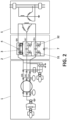
- the device of the invention is intended to be connected to a generator circuit breaker (2) that is connected between an electrical generation plant (1) and a transformer (5).
- the generator circuit breakers (2) are three-phase, and comprise one phase circuit breaker (4) for each phase.
- the device of the invention comprises two capacitors (3) with the same capacity for each phase, arranged one before and one after each phase circuit breaker (2), a first terminal of a first capacitor (31) being intended to be connected between the generation plant (1) and the generator circuit breaker (2), and a first terminal of a second capacitor (32) intended to be connected between the generator circuit breaker (2) and the transformer (5).
- a second terminal of each capacitor (31, 32) is connected to a monitoring module (7), in a double star configuration, as reflected in figure 2 .
- the monitoring module (7) is preferably a current transformer.
- the device comprises two capacitors (3) in total. In the event that the generator circuit breaker (2) is three-phase, as is common, the device comprises six capacitors (3) in total.
- the generator circuit breakers (2) of the state of the art is connected between a generation plant (1) and a transformer (5).
- the generator circuit breaker (2) comprises one phase circuit breaker (4) for each phase.
- Capacitors (3) are arranged before and after each phase circuit breaker (4), which capacitors are in turn connected to earth (6).
- a first possible failure is the short-circuit failure of a capacitor (3).
- an earth (6) failure occurs in one of the phases. This fault is detected by an earth (6) failure protection arranged in the generation plant (1), causing the generator circuit breaker (2) to trip immediately. This failure, except for the deterioration of the capacitor (3), does not cause further damage, unless there is a different sequence of subsequent events.
- the capacitor (3) that fails is the second capacitor (32) arranged between the generator circuit breaker (4) and the transformer (5)
- the development of the failure is different, as analysed below.
- the start of the failure is exactly the same, causing the plant SCRAM and the opening of the generator circuit breaker (4).
- the failure remains between the generator circuit breaker (4) and the transformer (5).
- earth (6) failure protections are activated and the 400 kV grid is lost until the failed capacitor (32) can be removed.
- a second possible failure is the open capacitor (3) failure.
- the consequence of this failure is the impossibility of being able to open the affected pole. In this case, there is no possibility of detecting it.
- a first failure possibility is that one of the capacitors (3) is short-circuited.
- the earth (6) failure system of the generation plant (1) since the entire assembly is isolated from earth (6). What does happen is that there is a change in the currents through each branch of capacitors (3), but it is not capable of activating any plant protection due to the low value of the current and there is no current circulation to earth (6). In no case does a short circuit between phases occur because there is always another capacitor (3) that limits the passage of current.
- the device of the invention with the capacitors (3) not connected to earth (6) presents great advantages in terms of the reliability of the generator circuit breaker (4) and, above all, of the generation plant. (1). This is due to the fact that up to six (one per condenser (3)) points referred to as single point vulnerabilities are removed.
- the present invention comprises a method for monitoring overvoltage protection capacitors in generator circuit breakers, comprising the steps of:
Landscapes
- Engineering & Computer Science (AREA)
- Power Engineering (AREA)
- Protection Of Generators And Motors (AREA)
Claims (4)
- Vorrichtung zur Überwachung von Überspannungsschutzkondensatoren in Generatorleistungsschaltern,wobei die Vorrichtung dazu bestimmt ist, mit einem Generatorleistungsschalter (2), GCB, verbunden zu werden, der zwischen einer Stromgenerierungsanlage (1) und einem Wandler (5) angeordnet ist, wobei der Generatorleistungsschalter (2) eine oder mehrere Phasen mit einem Phasenleistungsschalter (4) pro Phase umfasst,wobei die Vorrichtung einen ersten Kondensator (31) und einen zweiten Kondensator (32) für jede Phase des Generatorleistungsschalters (2) aufweist, wobei jeder Kondensator (31, 32) einen ersten Anschluss und einen zweiten Anschluss umfasst, wobei die Vorrichtung dadurch gekennzeichnet ist, dass sie zusätzlich Folgendes umfasst:
ein Überwachungsmodul (7) für das Durchgangserkennen, das dazu konfiguriert ist, ein Alarmsignal zu generieren, wenn ein Strom durch die Kondensatoren (31, 32) fließt, wobei der zweite Anschluss des ersten Kondensators (31) und der zweite Anschluss des zweiten Kondensators (32) mit dem Überwachungsmodul (7) in einer Doppelsternkonfiguration verbunden sind und der erste Anschluss des ersten Kondensators (31) dazu vorgesehen ist, zwischen der Generierungsanlage (1) und dem Generatorleistungsschalter (4) der Phase davon verbunden zu werden, und der erste Anschluss des zweiten Kondensators (32) dazu vorgesehen ist, zwischen dem Generatorleistungsschalter (4) der Phase davon und dem Wandler (5) verbunden zu werden. - Vorrichtung nach Anspruch 1, wobei das Überwachungsmodul (7) ein Stromwandler ist.
- Vorrichtung nach Anspruch 1, umfassend sechs Kondensatoren (31, 32), zwei für jede Phase des Generatorleistungsschalters (2).
- Verfahren zur Überwachung von Überspannungsschutzkondensatoren in Generatorleistungsschaltern, wobei ein Generatorleistungsschalter (2), GCB, eine oder mehrere Phasen mit einem Phasenleistungsschalter (4) pro Phase umfasst, wobei der Generatorleistungsschalter (2) zwischen einer Stromgenerierungsanlage (1) und einem Wandler (5) angeordnet ist,
wobei das Verfahren folgende Schritte umfasst:- Verbinden eines ersten Anschlusses eines ersten Kondensators (31) zwischen der Generierungsanlage (1) und dem Generatorleistungsschalter (4) der Phase davon,- Verbinden eines ersten Anschlusses eines zweiten Kondensators (32) zwischen dem Generatorleistungsschalter (4) der Phase davon und dem Wandler (5),- Verbinden eines zweiten Anschlusses des ersten Kondensators (31) und eines zweiten Anschlusses des zweiten Kondensators (32) mit einem Überwachungsmodul (7) in einer Doppelsternkonfiguration,- Erkennen eines durch die Kondensatoren (31, 32) fließenden Stroms im Überwachungsmodul (7) und- Generieren eines Alarmsignals im Überwachungsmodul (7), wenn ein Strom durch die Kondensatoren (31, 32) fließt.
Priority Applications (2)
| Application Number | Priority Date | Filing Date | Title |
|---|---|---|---|
| EP22382845.0A EP4339986B1 (de) | 2022-09-13 | 2022-09-13 | Einrichtung und verfahren zur überwachung von überspannungsschutzkondensatoren in generatorleistungsschaltern |
| ES22382845T ES3021983T3 (en) | 2022-09-13 | 2022-09-13 | Device and method for monitoring overvoltage protection capacitors in generator circuit breakers |
Applications Claiming Priority (1)
| Application Number | Priority Date | Filing Date | Title |
|---|---|---|---|
| EP22382845.0A EP4339986B1 (de) | 2022-09-13 | 2022-09-13 | Einrichtung und verfahren zur überwachung von überspannungsschutzkondensatoren in generatorleistungsschaltern |
Publications (3)
| Publication Number | Publication Date |
|---|---|
| EP4339986A1 EP4339986A1 (de) | 2024-03-20 |
| EP4339986B1 true EP4339986B1 (de) | 2025-02-26 |
| EP4339986C0 EP4339986C0 (de) | 2025-02-26 |
Family
ID=83898129
Family Applications (1)
| Application Number | Title | Priority Date | Filing Date |
|---|---|---|---|
| EP22382845.0A Active EP4339986B1 (de) | 2022-09-13 | 2022-09-13 | Einrichtung und verfahren zur überwachung von überspannungsschutzkondensatoren in generatorleistungsschaltern |
Country Status (2)
| Country | Link |
|---|---|
| EP (1) | EP4339986B1 (de) |
| ES (1) | ES3021983T3 (de) |
Families Citing this family (1)
| Publication number | Priority date | Publication date | Assignee | Title |
|---|---|---|---|---|
| CN120524888B (zh) * | 2025-07-23 | 2025-09-30 | 合肥工业大学 | 基于仿真参数变化的断路器切除并联电抗器过电压快速计算方法 |
Family Cites Families (3)
| Publication number | Priority date | Publication date | Assignee | Title |
|---|---|---|---|---|
| US4321643A (en) * | 1980-04-04 | 1982-03-23 | Amf Incorporated | Ground monitoring system |
| AU2015274548B2 (en) * | 2014-06-11 | 2017-02-16 | Asator Global Technologies Llc | Surge suppression system for medium and high voltage |
| CN114563670B (zh) * | 2022-03-01 | 2025-07-01 | 中国大唐集团科学技术研究院有限公司中南电力试验研究院 | 发电机出口断路器内冲击电容器绝缘在线监测装置及方法 |
-
2022
- 2022-09-13 EP EP22382845.0A patent/EP4339986B1/de active Active
- 2022-09-13 ES ES22382845T patent/ES3021983T3/es active Active
Also Published As
| Publication number | Publication date |
|---|---|
| EP4339986A1 (de) | 2024-03-20 |
| EP4339986C0 (de) | 2025-02-26 |
| ES3021983T3 (en) | 2025-05-28 |
Similar Documents
| Publication | Publication Date | Title |
|---|---|---|
| RU2553276C2 (ru) | Способ и компоновка для обнаружения внутренней неисправности в соединенной н-мостом батарее конденсаторов | |
| RU2761112C1 (ru) | Способ обнаружения обрыва фазы пускового/резервного трансформатора с использованием оптического трансформатора тока | |
| EP2676146B1 (de) | Verfahren und anordnung für interne fehlererkennung bei einer y-y-verbundenen kondensatorbank | |
| JP2019537701A (ja) | 高信頼性の配電ネットワーク故障の検出方法、装置及び記憶媒体 | |
| JP5256757B2 (ja) | 微地絡検出装置 | |
| US20180013280A1 (en) | A method of clearing a fault in a hvdc electrical network | |
| EP4339986B1 (de) | Einrichtung und verfahren zur überwachung von überspannungsschutzkondensatoren in generatorleistungsschaltern | |
| US11594875B1 (en) | Ground fault overvoltage detection using negative sequence voltage monitoring | |
| JPH11308757A (ja) | 電力系統の監視制御装置 | |
| EP3391489B1 (de) | Erdschlussdetektions- und schutzschaltungssystem | |
| US20220052518A1 (en) | Method of controlling a renewable power generation plant | |
| KR20010026829A (ko) | 배전계통의 지락/단락 발생 시험 장치 | |
| KR101200033B1 (ko) | 발전기 비동기투입 보호장치 | |
| CN108627795B (zh) | 监测电力设备的测量电路中电压互感器断路的方法与装置 | |
| EP2878964B1 (de) | Detektion kurzgeschlossener Dioden | |
| Kulmala et al. | Open phase condition scenarios for nuclear power plant electrical network studies | |
| CN114094553B (zh) | 输电系统的故障保护方法、装置、设备及输电系统 | |
| Blánquez et al. | Consideration of multi-phase criterion in the differential protection algorithm for high-impedance grounded synchronous generators | |
| Alla et al. | Improvements in Generator Breaker Failure Protection During Low-Current Conditions | |
| CN221380496U (zh) | 一种防止多台泵组并联运行时单相接地保护的优化装置 | |
| CN116316431B (zh) | 一种机端断路器非全相保护方法及装置 | |
| Korede et al. | Investigation of Transformer Lockout Event Caused by Breaker Failure Protection Misoperation | |
| KR20060056527A (ko) | 병렬 커패시터 뱅크의 전압 차동 보호 방법 및 장치 | |
| CN117650479A (zh) | 一种防止多台泵组并联运行时单相接地保护的优化方法及装置 | |
| Chen et al. | Analysis of an Accident of Incorrect Action of Relay Protection Device Due to Failure of Phase Selection |
Legal Events
| Date | Code | Title | Description |
|---|---|---|---|
| PUAI | Public reference made under article 153(3) epc to a published international application that has entered the european phase |
Free format text: ORIGINAL CODE: 0009012 |
|
| STAA | Information on the status of an ep patent application or granted ep patent |
Free format text: STATUS: THE APPLICATION HAS BEEN PUBLISHED |
|
| AK | Designated contracting states |
Kind code of ref document: A1 Designated state(s): AL AT BE BG CH CY CZ DE DK EE ES FI FR GB GR HR HU IE IS IT LI LT LU LV MC MK MT NL NO PL PT RO RS SE SI SK SM TR |
|
| STAA | Information on the status of an ep patent application or granted ep patent |
Free format text: STATUS: REQUEST FOR EXAMINATION WAS MADE |
|
| 17P | Request for examination filed |
Effective date: 20240319 |
|
| RBV | Designated contracting states (corrected) |
Designated state(s): AL AT BE BG CH CY CZ DE DK EE ES FI FR GB GR HR HU IE IS IT LI LT LU LV MC MK MT NL NO PL PT RO RS SE SI SK SM TR |
|
| GRAP | Despatch of communication of intention to grant a patent |
Free format text: ORIGINAL CODE: EPIDOSNIGR1 |
|
| STAA | Information on the status of an ep patent application or granted ep patent |
Free format text: STATUS: GRANT OF PATENT IS INTENDED |
|
| INTG | Intention to grant announced |
Effective date: 20240910 |
|
| RIC1 | Information provided on ipc code assigned before grant |
Ipc: H02J 13/00 20060101ALI20240830BHEP Ipc: H02J 3/00 20060101ALI20240830BHEP Ipc: H02H 7/06 20060101ALI20240830BHEP Ipc: H01H 47/00 20060101AFI20240830BHEP |
|
| GRAS | Grant fee paid |
Free format text: ORIGINAL CODE: EPIDOSNIGR3 |
|
| GRAA | (expected) grant |
Free format text: ORIGINAL CODE: 0009210 |
|
| STAA | Information on the status of an ep patent application or granted ep patent |
Free format text: STATUS: THE PATENT HAS BEEN GRANTED |
|
| AK | Designated contracting states |
Kind code of ref document: B1 Designated state(s): AL AT BE BG CH CY CZ DE DK EE ES FI FR GB GR HR HU IE IS IT LI LT LU LV MC MK MT NL NO PL PT RO RS SE SI SK SM TR |
|
| REG | Reference to a national code |
Ref country code: GB Ref legal event code: FG4D |
|
| REG | Reference to a national code |
Ref country code: CH Ref legal event code: EP |
|
| REG | Reference to a national code |
Ref country code: DE Ref legal event code: R096 Ref document number: 602022011088 Country of ref document: DE |
|
| REG | Reference to a national code |
Ref country code: IE Ref legal event code: FG4D |
|
| U01 | Request for unitary effect filed |
Effective date: 20250326 |
|
| U07 | Unitary effect registered |
Designated state(s): AT BE BG DE DK EE FI FR IT LT LU LV MT NL PT RO SE SI Effective date: 20250401 |
|
| REG | Reference to a national code |
Ref country code: ES Ref legal event code: FG2A Ref document number: 3021983 Country of ref document: ES Kind code of ref document: T3 Effective date: 20250528 |
|
| PG25 | Lapsed in a contracting state [announced via postgrant information from national office to epo] |
Ref country code: RS Free format text: LAPSE BECAUSE OF FAILURE TO SUBMIT A TRANSLATION OF THE DESCRIPTION OR TO PAY THE FEE WITHIN THE PRESCRIBED TIME-LIMIT Effective date: 20250526 |
|
| PG25 | Lapsed in a contracting state [announced via postgrant information from national office to epo] |
Ref country code: PL Free format text: LAPSE BECAUSE OF FAILURE TO SUBMIT A TRANSLATION OF THE DESCRIPTION OR TO PAY THE FEE WITHIN THE PRESCRIBED TIME-LIMIT Effective date: 20250226 |
|
| PG25 | Lapsed in a contracting state [announced via postgrant information from national office to epo] |
Ref country code: NO Free format text: LAPSE BECAUSE OF FAILURE TO SUBMIT A TRANSLATION OF THE DESCRIPTION OR TO PAY THE FEE WITHIN THE PRESCRIBED TIME-LIMIT Effective date: 20250526 Ref country code: IS Free format text: LAPSE BECAUSE OF FAILURE TO SUBMIT A TRANSLATION OF THE DESCRIPTION OR TO PAY THE FEE WITHIN THE PRESCRIBED TIME-LIMIT Effective date: 20250626 |
|
| PG25 | Lapsed in a contracting state [announced via postgrant information from national office to epo] |
Ref country code: HR Free format text: LAPSE BECAUSE OF FAILURE TO SUBMIT A TRANSLATION OF THE DESCRIPTION OR TO PAY THE FEE WITHIN THE PRESCRIBED TIME-LIMIT Effective date: 20250226 |
|
| PG25 | Lapsed in a contracting state [announced via postgrant information from national office to epo] |
Ref country code: GR Free format text: LAPSE BECAUSE OF FAILURE TO SUBMIT A TRANSLATION OF THE DESCRIPTION OR TO PAY THE FEE WITHIN THE PRESCRIBED TIME-LIMIT Effective date: 20250527 |
|
| PG25 | Lapsed in a contracting state [announced via postgrant information from national office to epo] |
Ref country code: SM Free format text: LAPSE BECAUSE OF FAILURE TO SUBMIT A TRANSLATION OF THE DESCRIPTION OR TO PAY THE FEE WITHIN THE PRESCRIBED TIME-LIMIT Effective date: 20250226 |
|
| U20 | Renewal fee for the european patent with unitary effect paid |
Year of fee payment: 4 Effective date: 20250903 |
|
| PG25 | Lapsed in a contracting state [announced via postgrant information from national office to epo] |
Ref country code: CZ Free format text: LAPSE BECAUSE OF FAILURE TO SUBMIT A TRANSLATION OF THE DESCRIPTION OR TO PAY THE FEE WITHIN THE PRESCRIBED TIME-LIMIT Effective date: 20250226 |
|
| PG25 | Lapsed in a contracting state [announced via postgrant information from national office to epo] |
Ref country code: SK Free format text: LAPSE BECAUSE OF FAILURE TO SUBMIT A TRANSLATION OF THE DESCRIPTION OR TO PAY THE FEE WITHIN THE PRESCRIBED TIME-LIMIT Effective date: 20250226 |