EP4339527A1 - Inspection device and inspection method - Google Patents
Inspection device and inspection method Download PDFInfo
- Publication number
- EP4339527A1 EP4339527A1 EP21941806.8A EP21941806A EP4339527A1 EP 4339527 A1 EP4339527 A1 EP 4339527A1 EP 21941806 A EP21941806 A EP 21941806A EP 4339527 A1 EP4339527 A1 EP 4339527A1
- Authority
- EP
- European Patent Office
- Prior art keywords
- refrigerant
- valve
- outdoor unit
- unit
- refrigerant path
- Prior art date
- Legal status (The legal status is an assumption and is not a legal conclusion. Google has not performed a legal analysis and makes no representation as to the accuracy of the status listed.)
- Pending
Links
- 238000007689 inspection Methods 0.000 title claims description 13
- 238000000034 method Methods 0.000 title claims description 10
- 239000003507 refrigerant Substances 0.000 claims abstract description 159
- 230000008054 signal transmission Effects 0.000 claims abstract description 23
- 238000002347 injection Methods 0.000 claims description 28
- 239000007924 injection Substances 0.000 claims description 28
- 239000003921 oil Substances 0.000 claims description 25
- 239000010726 refrigerant oil Substances 0.000 claims description 7
- 239000007788 liquid Substances 0.000 description 66
- 238000010586 diagram Methods 0.000 description 10
- 238000004891 communication Methods 0.000 description 9
- 238000009434 installation Methods 0.000 description 7
- 230000006870 function Effects 0.000 description 6
- 230000007246 mechanism Effects 0.000 description 5
- 238000005057 refrigeration Methods 0.000 description 5
- 238000003860 storage Methods 0.000 description 5
- 238000001514 detection method Methods 0.000 description 4
- 230000009993 protective function Effects 0.000 description 4
- 238000001816 cooling Methods 0.000 description 3
- 230000001681 protective effect Effects 0.000 description 3
- 239000000243 solution Substances 0.000 description 3
- 230000002159 abnormal effect Effects 0.000 description 2
- 230000000694 effects Effects 0.000 description 2
- 230000009467 reduction Effects 0.000 description 2
- 238000004378 air conditioning Methods 0.000 description 1
- 230000005540 biological transmission Effects 0.000 description 1
- 230000008859 change Effects 0.000 description 1
- 238000009826 distribution Methods 0.000 description 1
- 238000010438 heat treatment Methods 0.000 description 1
- 238000005461 lubrication Methods 0.000 description 1
- 230000003287 optical effect Effects 0.000 description 1
- 230000008569 process Effects 0.000 description 1
- 238000004904 shortening Methods 0.000 description 1
Images


Classifications
-
- F—MECHANICAL ENGINEERING; LIGHTING; HEATING; WEAPONS; BLASTING
- F25—REFRIGERATION OR COOLING; COMBINED HEATING AND REFRIGERATION SYSTEMS; HEAT PUMP SYSTEMS; MANUFACTURE OR STORAGE OF ICE; LIQUEFACTION SOLIDIFICATION OF GASES
- F25B—REFRIGERATION MACHINES, PLANTS OR SYSTEMS; COMBINED HEATING AND REFRIGERATION SYSTEMS; HEAT PUMP SYSTEMS
- F25B13/00—Compression machines, plants or systems, with reversible cycle
-
- F—MECHANICAL ENGINEERING; LIGHTING; HEATING; WEAPONS; BLASTING
- F25—REFRIGERATION OR COOLING; COMBINED HEATING AND REFRIGERATION SYSTEMS; HEAT PUMP SYSTEMS; MANUFACTURE OR STORAGE OF ICE; LIQUEFACTION SOLIDIFICATION OF GASES
- F25B—REFRIGERATION MACHINES, PLANTS OR SYSTEMS; COMBINED HEATING AND REFRIGERATION SYSTEMS; HEAT PUMP SYSTEMS
- F25B49/00—Arrangement or mounting of control or safety devices
- F25B49/02—Arrangement or mounting of control or safety devices for compression type machines, plants or systems
-
- F—MECHANICAL ENGINEERING; LIGHTING; HEATING; WEAPONS; BLASTING
- F25—REFRIGERATION OR COOLING; COMBINED HEATING AND REFRIGERATION SYSTEMS; HEAT PUMP SYSTEMS; MANUFACTURE OR STORAGE OF ICE; LIQUEFACTION SOLIDIFICATION OF GASES
- F25B—REFRIGERATION MACHINES, PLANTS OR SYSTEMS; COMBINED HEATING AND REFRIGERATION SYSTEMS; HEAT PUMP SYSTEMS
- F25B2313/00—Compression machines, plants or systems with reversible cycle not otherwise provided for
- F25B2313/006—Compression machines, plants or systems with reversible cycle not otherwise provided for two pipes connecting the outdoor side to the indoor side with multiple indoor units
-
- F—MECHANICAL ENGINEERING; LIGHTING; HEATING; WEAPONS; BLASTING
- F25—REFRIGERATION OR COOLING; COMBINED HEATING AND REFRIGERATION SYSTEMS; HEAT PUMP SYSTEMS; MANUFACTURE OR STORAGE OF ICE; LIQUEFACTION SOLIDIFICATION OF GASES
- F25B—REFRIGERATION MACHINES, PLANTS OR SYSTEMS; COMBINED HEATING AND REFRIGERATION SYSTEMS; HEAT PUMP SYSTEMS
- F25B2313/00—Compression machines, plants or systems with reversible cycle not otherwise provided for
- F25B2313/023—Compression machines, plants or systems with reversible cycle not otherwise provided for using multiple indoor units
- F25B2313/0233—Compression machines, plants or systems with reversible cycle not otherwise provided for using multiple indoor units in parallel arrangements
-
- F—MECHANICAL ENGINEERING; LIGHTING; HEATING; WEAPONS; BLASTING
- F25—REFRIGERATION OR COOLING; COMBINED HEATING AND REFRIGERATION SYSTEMS; HEAT PUMP SYSTEMS; MANUFACTURE OR STORAGE OF ICE; LIQUEFACTION SOLIDIFICATION OF GASES
- F25B—REFRIGERATION MACHINES, PLANTS OR SYSTEMS; COMBINED HEATING AND REFRIGERATION SYSTEMS; HEAT PUMP SYSTEMS
- F25B2400/00—General features or devices for refrigeration machines, plants or systems, combined heating and refrigeration systems or heat-pump systems, i.e. not limited to a particular subgroup of F25B
- F25B2400/13—Economisers
-
- F—MECHANICAL ENGINEERING; LIGHTING; HEATING; WEAPONS; BLASTING
- F25—REFRIGERATION OR COOLING; COMBINED HEATING AND REFRIGERATION SYSTEMS; HEAT PUMP SYSTEMS; MANUFACTURE OR STORAGE OF ICE; LIQUEFACTION SOLIDIFICATION OF GASES
- F25B—REFRIGERATION MACHINES, PLANTS OR SYSTEMS; COMBINED HEATING AND REFRIGERATION SYSTEMS; HEAT PUMP SYSTEMS
- F25B2500/00—Problems to be solved
- F25B2500/22—Preventing, detecting or repairing leaks of refrigeration fluids
- F25B2500/222—Detecting refrigerant leaks
-
- F—MECHANICAL ENGINEERING; LIGHTING; HEATING; WEAPONS; BLASTING
- F25—REFRIGERATION OR COOLING; COMBINED HEATING AND REFRIGERATION SYSTEMS; HEAT PUMP SYSTEMS; MANUFACTURE OR STORAGE OF ICE; LIQUEFACTION SOLIDIFICATION OF GASES
- F25B—REFRIGERATION MACHINES, PLANTS OR SYSTEMS; COMBINED HEATING AND REFRIGERATION SYSTEMS; HEAT PUMP SYSTEMS
- F25B2600/00—Control issues
- F25B2600/25—Control of valves
- F25B2600/2509—Economiser valves
-
- F—MECHANICAL ENGINEERING; LIGHTING; HEATING; WEAPONS; BLASTING
- F25—REFRIGERATION OR COOLING; COMBINED HEATING AND REFRIGERATION SYSTEMS; HEAT PUMP SYSTEMS; MANUFACTURE OR STORAGE OF ICE; LIQUEFACTION SOLIDIFICATION OF GASES
- F25B—REFRIGERATION MACHINES, PLANTS OR SYSTEMS; COMBINED HEATING AND REFRIGERATION SYSTEMS; HEAT PUMP SYSTEMS
- F25B2600/00—Control issues
- F25B2600/25—Control of valves
- F25B2600/2519—On-off valves
-
- F—MECHANICAL ENGINEERING; LIGHTING; HEATING; WEAPONS; BLASTING
- F25—REFRIGERATION OR COOLING; COMBINED HEATING AND REFRIGERATION SYSTEMS; HEAT PUMP SYSTEMS; MANUFACTURE OR STORAGE OF ICE; LIQUEFACTION SOLIDIFICATION OF GASES
- F25B—REFRIGERATION MACHINES, PLANTS OR SYSTEMS; COMBINED HEATING AND REFRIGERATION SYSTEMS; HEAT PUMP SYSTEMS
- F25B2700/00—Sensing or detecting of parameters; Sensors therefor
- F25B2700/19—Pressures
- F25B2700/193—Pressures of the compressor
- F25B2700/1931—Discharge pressures
-
- F—MECHANICAL ENGINEERING; LIGHTING; HEATING; WEAPONS; BLASTING
- F25—REFRIGERATION OR COOLING; COMBINED HEATING AND REFRIGERATION SYSTEMS; HEAT PUMP SYSTEMS; MANUFACTURE OR STORAGE OF ICE; LIQUEFACTION SOLIDIFICATION OF GASES
- F25B—REFRIGERATION MACHINES, PLANTS OR SYSTEMS; COMBINED HEATING AND REFRIGERATION SYSTEMS; HEAT PUMP SYSTEMS
- F25B2700/00—Sensing or detecting of parameters; Sensors therefor
- F25B2700/19—Pressures
- F25B2700/193—Pressures of the compressor
- F25B2700/1933—Suction pressures
Definitions
- the present disclosure relates to a technique of inspecting whether a valve provided in a refrigerant path of an air conditioner is closed or not.
- a liquid pipe valve and a gas pipe valve are placed in inlet and outlet portions of a refrigerant path (to be referred to below as a first refrigerant path) to circulate refrigerant between an outdoor unit and an outdoor unit of an air conditioner.
- a refrigerant path to circulate refrigerant between an outdoor unit and an outdoor unit of an air conditioner.
- the liquid pipe valve and the gas pipe valve are also referred to collectively as a first valve.
- the first valve needs to be brought into an open state by an operator when the air conditioner is installed.
- the first valve When the first valve is in a closed state or when the first valve is not fully opened, the first refrigerant path is blocked so that the refrigerant is not circulated. Accordingly, it is assumed that an expected air conditioning capability is not fulfilled. Otherwise, it is assumed that power consumption may increase with increase in pressure loss.
- a pressure difference between a low pressure (inlet pressure) and a high pressure (discharge pressure) may increase, so that the air conditioner may be stopped due to protective control for protection of the air conditioner.
- the air conditioner is stopped in this manner, the operator needs to examine a cause of stoppage. Meanwhile, when operation of the air conditioner continues in spite of the protective control, the operator needs to avoid overlooking the first valve in the closed state.
- Patent Literature 1 a technique of detecting whether the first valve is in the closed state or not is disclosed in Patent Literature 1.
- Patent Literature 1 JP 2007-107820
- Patent Literature 1 has a problem in that it may be incorrectly determined that the first valve is open though the first valve is closed.
- the present disclosure mainly aims at solving such a problem. More specifically, the present disclosure mainly aims at making it possible to correctly determine whether the first valve is closed or not even if an outdoor unit in which the second refrigerant path exists is used.
- An inspection device includes:
- the present disclosure it can be correctly determined whether the first valve is closed or not even if the outdoor unit in which the second refrigerant path exists is used.
- Fig. 1 illustrates a configuration example of an anomaly detection system according to the present embodiment.
- the anomaly detection system includes an air conditioner 1, a command device 2, a display 3, and an anomaly determination device 4.
- the air conditioner 1, the command device 2, and the display 3 are connected to the anomaly determination device 4.
- the command device 2 commands the air conditioner 1 to start commissioning.
- the command device 2 is a remote controller for the air conditioner 1 or a PC (Personal Computer) connected to the air conditioner 1, for instance.
- PC Personal Computer
- the display 3 When a closed state of a liquid pipe valve 15 and/or a gas pipe valve 16 that will be described later is detected, the display 3 displays a message making notification that the liquid pipe valve 15 and/or the gas pipe valve 16 is in the closed state. Display of the message by the display 3 makes it possible for an operator who does installation work for the air conditioner 1 to recognize that the liquid pipe valve 15 and/or the gas pipe valve 16 is in the closed state.
- the display 3 is a remote controller for the air conditioner 1 or a PC connected to the air conditioner 1, for instance.
- the command device 2 and the display 3 may be implemented as the same device.
- the anomaly determination device 4 is a computer. If the command device 2 and/or the display 3 is implemented by the PC, the anomaly determination device 4 may be implemented by the same PC as the command device 2 and/or the display 3.
- the anomaly determination device 4 includes a communication instrument 110 and a processor 120. Further, a storage device such as a RAM (Random Access Memory) or an HDD (Hard Disk Drive) is supposed to be included in the anomaly determination device 4, though not illustrated.
- a RAM Random Access Memory
- HDD Hard Disk Drive
- the communication instrument 110 communicates with the air conditioner 1, the command device 2, and the display 3.
- the processor 120 executes programs that realize functions of a signal transmission unit 121, an operation data acquisition unit 122, a determination unit 123, and a report unit 124.
- the processor 120 executes the programs to function as the signal transmission unit 121, the operation data acquisition unit 122, the determination unit 123, and the report unit 124. Details of the signal transmission unit 121, the operation data acquisition unit 122, the determination unit 123, and the report unit 124 will be described later.
- the anomaly determination device 4 is equivalent to an inspection device. Further, an operation procedure of the anomaly determination device 4 is equivalent to an inspection method.
- Fig. 2 illustrates a configuration example of the air conditioner 1.
- the air conditioner 1 includes an outdoor unit 10, indoor units 20, and connection pipes 30 to connect the outdoor unit 10 and the indoor units 20.
- Fig. 2 illustrates a configuration in which the plurality of indoor units 20 are connected to the one outdoor unit 10.
- the configuration of the air conditioner 1, however, is not limited to that illustrated in Fig. 2 .
- the air conditioner 1 may have a configuration in which one indoor unit 20 is connected to the one outdoor unit 10.
- a plurality of outdoor units 10 may be included in the air conditioner 1.
- the outdoor unit 10 includes a compressor 11, a four-way valve 12, an outdoor heat exchanger 13, an outdoor unit fan 14, the liquid pipe valve 15, the gas pipe valve 16, a subcool coil 17, and an expansion valve 18 for subcool coil.
- the indoor units 20 each include an expansion valve 21, an indoor heat exchanger 22, and an indoor unit fan 23.
- a refrigeration cycle is configured by ring-like connection of the compressor 11, the four-way valve 12, the outdoor heat exchanger 13, the expansion valve 21, and the indoor heat exchanger 22 through refrigerant pipes.
- the outdoor unit 10 includes a communication instrument to receive a command signal from the anomaly determination device 4, though not illustrated in Fig. 2 . Further, the outdoor unit 10 includes a valve control mechanism to close the expansion valve 18 for subcool coil based on the command signal.
- the command signal is a signal by which the anomaly determination device 4 commands the outdoor unit 10 to close the expansion valve 18 for subcool coil.
- the compressor 11 compresses refrigerant having a low temperature and a low pressure and thereby converts the refrigerant having the low temperature and the low pressure into the refrigerant having a high temperature and a high pressure.
- the compressor 11 is driven by an inverter, for instance, and has a controlled capacity (amount of the refrigerant to be discharged per unit time).
- the four-way valve 12 switches flow of the refrigerant, in accordance with an operation mode of the air conditioner 1, such as cooling operation or heating operation.
- the outdoor heat exchanger 13 carries out heat exchange between the refrigerant flowing through the refrigeration cycle and outdoor air.
- the outdoor unit fan 14 adjoins the outdoor heat exchanger 13.
- the outdoor unit fan 14 blows air against the outdoor heat exchanger 13. An amount of the blown air can be adjusted by control over the number of revolutions of the outdoor unit fan 14.
- the expansion valve 21 includes a valve whose opening can be variably controlled, such as an electronic expansion valve. A pressure reduction amount for the refrigerant is controlled by control over the opening of the expansion valve 21.
- the indoor heat exchanger 22 carries out heat exchange between the refrigerant flowing through the refrigeration cycle and indoor air.
- the indoor unit fan 23 adjoins the indoor heat exchanger 22.
- the indoor unit fan 23 blows air against the indoor heat exchanger 22. An amount of the blown air can be adjusted by control over the number of revolutions of the indoor unit fan 23.
- a high-pressure sensor 41 and a low-pressure sensor 42 are installed ahead and behind the compressor 11 of the outdoor unit 10.
- the high-pressure sensor 41 measures a high pressure value (discharge pressure value) of the refrigerant in the compressor 11.
- the low-pressure sensor 42 measures a low pressure value (inlet pressure value) of the refrigerant in the compressor 11.
- the high-pressure sensor 41 and the low-pressure sensor 42 are used when control for making the high pressure and the low pressure close to target values is exerted. Further, the high-pressure sensor 41 and the low-pressure sensor 42 are used for protective control for preventing the outdoor unit 10 from being damaged by increase in the high pressure and decrease in the low pressure.
- the liquid pipe valve 15 and the gas pipe valve 16 are provided in connection portions between the outdoor unit 10 and the connection pipes 30.
- the operator who does the installation work installs the air conditioner 1 by connecting the outdoor unit 10, the indoor units 20, and the connection pipes 30 at an installation site. During shipment and transfer, the liquid pipe valve 15 and the gas pipe valve 16 are closed. After the outdoor unit 10, the indoor units 20, and the connection pipes 30 are connected at the installation site, the operator opens the liquid pipe valve 15 and the gas pipe valve 16. Opening the liquid pipe valve 15 and the gas pipe valve 16 enables circulation of the refrigerant.
- the liquid pipe valve 15 and the gas pipe valve 16 are equivalent to first valves.
- degree of undercooling can be increased by reduction in pressure of a portion of the refrigerant, having gone out of the outdoor heat exchanger 13 and having a high pressure, by the expansion valve 18 for subcool coil and heat exchange in the subcool coil 17 between the refrigerant reduced in the pressure and the refrigerant before diverging.
- the refrigerant reduced in the pressure is returned to the compressor 11.
- the expansion valve 18 for subcool coil is equivalent to a second valve.
- Figs. 3 and 4 illustrate the two refrigerant paths existing in the outdoor unit 10.
- Fig. 3 illustrates a first refrigerant path and Fig. 4 illustrates a second refrigerant path.
- the refrigerant that flows in from the indoor units 20 is returned through the gas pipe valve 16, the low-pressure sensor 42, the compressor 11, the high-pressure sensor 41, the outdoor heat exchanger 13, the subcool coil 17, and the liquid pipe valve 15 to the indoor units 20.
- the first refrigerant path makes the refrigerant circulate between the outdoor unit 10 and the indoor units 20.
- the second refrigerant path of Fig. 4 is a path to make the refrigerant circulate in the outdoor unit 10. That is, the second refrigerant path is a path extending through the outdoor heat exchanger 13, the subcool coil 17, the expansion valve 18 for subcool coil, the low-pressure sensor 42, the compressor 11, and the high-pressure sensor 41.
- a high-low pressure difference increases when the compressor 11 operates, compared with a case where both the valves are normally open.
- the high-low pressure difference exceeds a predetermined threshold, it can be determined that the liquid pipe valve 15 and/or the gas pipe valve 16 may be in the closed state.
- the refrigerant is allowed to circulate through the second refrigerant path by the expansion valve 18 for subcool coil being open even if the circulation of the refrigerant through the first refrigerant path is blocked by closure of the liquid pipe valve 15 and the gas pipe valve 16.
- the high-low pressure difference does not increase to be greater than or equal to the threshold.
- the anomaly determination device 4 has a configuration that enables correctly determining whether the liquid pipe valve 15 and/or the gas pipe valve 16 is closed or not even though the second refrigerant path exists in the outdoor unit 10.
- the signal transmission unit 121 transmits a command signal to the outdoor unit 10 in the commissioning of the air conditioner 1.
- the command signal is a signal that commands closure of the expansion valve 18 for subcool coil.
- the outdoor unit 10 having received the command signal closes the expansion valve 18 for subcool coil, if the expansion valve 18 for subcool coil is open.
- the circulation of the refrigerant in a second refrigerant circuit is blocked by closure of the expansion valve 18 for subcool coil.
- Blockage of the circulation of the refrigerant in the second refrigerant circuit by the closure of the expansion valve 18 for subcool coil makes it possible for the determination unit 123 that will be described later to correctly determine the state of the liquid pipe valve 15 and/or the gas pipe valve 16.
- the operation data acquisition unit 122 acquires operation data on the air conditioner 1.
- the operation data is sensor values obtained from a sensor provided in the air conditioner 1, for instance. Further, the operation data is controlling values for the air conditioner 1. In the sensor values, the high pressure value measured by the high-pressure sensor 41 and the low pressure value measured by the low-pressure sensor 42 are included. In the controlling values, such values as a frequency of the compressor 11, the number of revolutions of the outdoor unit fan 14, and the valve opening of the expansion valve 21 are included.
- the operation data acquisition unit 122 acquires the high pressure value measured by the high-pressure sensor 41 and the low pressure value measured by the low-pressure sensor 42 after transmission of the command signal from the signal transmission unit 121.
- the determination unit 123 determines whether the liquid pipe valve 15 and/or the gas pipe valve 16 is in the closed state or not, based on the high pressure value and the low pressure value acquired as the operation data by the operation data acquisition unit 122. As described above, the determination unit 123 determines that the liquid pipe valve 15 and/or the gas pipe valve 16 is in the closed state, when the high-low pressure difference which is the pressure difference between the high pressure value and the low pressure value exceeds the threshold.
- the determination unit 123 may determine that the liquid pipe valve 15 and/or the gas pipe valve 16 is in the closed state, when the high pressure exceeds a predetermined threshold. Meanwhile, the determination unit 123 may determine that the liquid pipe valve 15 and/or the gas pipe valve 16 is in the closed state, when the low pressure is lower than a predetermined threshold.
- the determination unit 123 may determine that the liquid pipe valve 15 and/or the gas pipe valve 16 is in the closed state, when operation of the air conditioner 1 is stopped by exercise of the protective function due to increase in the high pressure or decrease in the low pressure.
- the report unit 124 reports to the operator that the liquid pipe valve 15 and/or the gas pipe valve 16 is in the closed state. Specifically, the report unit 124 outputs to the display 3, a message of notification that the liquid pipe valve 15 and/or the gas pipe valve 16 is in the closed state.
- Fig. 5 illustrates an example of operation of the anomaly determination device 4 according to the present embodiment.
- the operation of the anomaly determination device 4 according to the present Embodiment 1 will be described with reference to a flow of Fig. 5 .
- the commissioning of the air conditioner 1 is started.
- the operation data acquisition unit 122 acquires the controlling values as the operation data and recognizes the start of the commissioning of the air conditioner 1.
- step ST01 the signal transmission unit 121 transmits the command signal to the outdoor unit 10.
- the outdoor unit 10 having received the command signal closes the expansion valve 18 for subcool coil, based on the command signal.
- step ST02 the operation data acquisition unit 122 acquires the high pressure value from the high-pressure sensor 41. Further, the operation data acquisition unit 122 acquires the low pressure value from the low-pressure sensor 42. Further, the determination unit 123 calculates the high-low pressure difference ⁇ P (high pressure value minus low pressure value) that is the difference between the high pressure value and the low pressure value.
- ⁇ P high pressure value minus low pressure value
- step ST03 the determination unit 123 determines whether the high-low pressure difference ⁇ P exceeds the predetermined threshold or not.
- step ST04 When the high-low pressure difference ⁇ P exceeds the threshold, processing proceeds to step ST04. On the other hand, when the high-low pressure difference ⁇ P is smaller than or equal to the threshold, the processing is ended.
- step ST04 the determination unit 123 determines that the liquid pipe valve 15 and/or the gas pipe valve 16 is in the closed state. Then, the report unit 124 outputs to the display 3, the message of notification that the liquid pipe valve 15 and/or the gas pipe valve 16 is in the closed state. The display 3 displays the message of the notification that the liquid pipe valve 15 and/or the gas pipe valve 16 is in the closed state.
- the operator having looked at the message displayed by the display 3 checks the liquid pipe valve 15 and the gas pipe valve 16 and, if the liquid pipe valve 15 and/or the gas pipe valve 16 is in the closed state, does opening work for the liquid pipe valve 15 and/or the gas pipe valve 16.
- the determination unit 123 may make a comparison between the high pressure value and the threshold instead of a comparison between the high-low pressure difference ⁇ P and the threshold, as described above.
- the determination unit 123 determines that the liquid pipe valve 15 and/or the gas pipe valve 16 is in the closed state.
- step ST02 in this case, it is sufficient if the operation data acquisition unit 122 acquires only the high pressure value and the determination unit 123 does not need to calculate the high-low pressure difference ⁇ P.
- the determination unit 123 may make a comparison between the low pressure value and the threshold instead of a comparison between the high-low pressure difference ⁇ P and the threshold, as described above.
- the determination unit 123 determines that the liquid pipe valve 15 and/or the gas pipe valve 16 is in the closed state.
- step ST02 in this case, it is sufficient if the operation data acquisition unit 122 acquires only the low pressure value and the determination unit 123 does not need to calculate the high-low pressure difference ⁇ P.
- the determination unit 123 may make a determination of whether the operation of the air conditioner 1 is stopped or not by the exercise of the protective function due to the increase in the high pressure or the decrease in the low pressure, instead of the comparison between the high-low pressure difference ⁇ P and the threshold, as described above.
- the determination unit 123 may determine that the liquid pipe valve 15 and/or the gas pipe valve 16 is in the closed state.
- the operation data acquisition unit 122 acquires the controlling values representing stoppage of the operation of the air conditioner 1, as the operation data, in step ST02. Then, the determination unit 123 analyzes the controlling values and recognizes that the operation of the air conditioner 1 is stopped by the exercise of the protective function due to the increase in the high pressure or the decrease in the low pressure.
- the threshold to be compared with the high-low pressure difference ⁇ P may be a fixed value or may be a variable value.
- the determination unit 123 changes the threshold in accordance with an operating condition of the air conditioner 1, such as the frequency of the compressor 11 or the opening of the expansion valve 21 of the indoor unit 20. Detection accuracy under a condition that the liquid pipe valve 15 and/or the gas pipe valve 16 is not fully-closed can be improved by such change in the threshold in accordance with the operating condition by the determination unit 123.
- the determination unit 123 may use a variable threshold that changes in accordance with the operating condition of the air conditioner 1, as the threshold to be compared with the high pressure value.
- the determination unit 123 may use a variable threshold that changes in accordance with the operating condition of the air conditioner 1, as the threshold to be compared with the low pressure value.
- the anomaly determination device 4 may command opening of the liquid pipe valve 15 and/or the gas pipe valve 16 to the outdoor unit 10, so that the liquid pipe valve 15 and/or the gas pipe valve 16 may be automatically opened.
- the outdoor unit 10 is supposed to include the valve control mechanism, not illustrated in Fig. 2 , to control opening and closure of the liquid pipe valve 15 and the gas pipe valve 16.
- the signal transmission unit 121 transmits to the outdoor unit 10, a command signal commanding the opening of the liquid pipe valve 15 and/or the gas pipe valve 16.
- the outdoor unit 10 having received the command signal opens the liquid pipe valve 15 and/or the gas pipe valve 16 through control over the valve control mechanism.
- a work burden on the operator can be relieved by such automatic opening of the liquid pipe valve 15 and/or the gas pipe valve 16.
- output of the message to the display 3 by the report unit 124 may be omitted.
- the anomaly determination device 4 transmits to the outdoor unit 10, the command signal commanding the closure of the expansion valve 18 for subcool coil, and the outdoor unit 10 closes the expansion valve 18 for subcool coil. According to the present embodiment, therefore, the anomaly determination device 4 is capable of correctly determining whether the liquid pipe valve 15 and/or the gas pipe valve 16 is closed or not even though the second refrigerant path exists in the outdoor unit 10. As a result, the operator can be notified in the commissioning that the liquid pipe valve 15 and/or the gas pipe valve 16 is in the closed state even if the operator forgets to open the liquid pipe valve 15 and/or the gas pipe valve 16 in the installation work. Further, shortening of working hours is facilitated because, even if abnormal stoppage occurs in the commissioning, the operator can recognize that the abnormal stoppage has been caused by the closure of the liquid pipe valve 15 and/or the gas pipe valve 16.
- Embodiment 1 the outdoor unit 10 having the configuration illustrated in Fig. 2 , that is, the outdoor unit 10 including the subcool coil 17 and the expansion valve 18 for subcool coil and including the second refrigerant path illustrated in Fig. 4 has been described.
- Embodiment 1 differences from Embodiment 1 will be principally described.
- Fig. 6 illustrates a configuration example of the air conditioner 1 according to the present embodiment.
- the indoor units 20 and the connection pipes 30 are the same as those illustrated in Fig. 2 and description thereof is therefore omitted.
- the four-way valve 12, the outdoor heat exchanger 13, the outdoor unit fan 14, the liquid pipe valve 15, the gas pipe valve 16, the high-pressure sensor 41, and the low-pressure sensor 41 in the outdoor unit 10 are the same as those illustrated in Fig. 2 and description thereof is therefore omitted.
- an injection compressor 111 is provided in place of the compressor 11 illustrated in Fig. 2 .
- the injection compressor 111 has a connection opening for intermediate pressure in addition to a connection opening for discharge pressure and a connection opening for inlet pressure.
- an expansion valve 118 for injection is provided in place of the expansion valve 18 for subcool coil illustrated in Fig. 2 .
- the expansion valve 118 for injection adjusts an injection amount to be injected from an injection pipe 119 into the intermediate pressure of the injection compressor 111.
- the expansion valve 118 for injection is equivalent to the second valve.
- an economizer 117 is provided in place of the subcool coil 17 illustrated in Fig. 2 .
- the economizer 117 recovers heat from liquid refrigerant having flowed out of the outdoor heat exchanger 13, by the refrigerant with the intermediate pressure.
- refrigeration cycle efficiency can be improved in the cooling operation by diverging of a portion of the liquid refrigerant having flowed out of the outdoor heat exchanger 13 and injection thereof into the intermediate pressure of the injection compressor 111.
- the outdoor unit 10 is supposed to include a valve control mechanism that is not illustrated in Fig. 6 and that is to close the expansion valve 118 for injection based on a command signal.
- a first refrigerant path and a second refrigerant path exist in the outdoor unit 10 according to the present embodiment as well.
- Fig. 7 illustrates the first refrigerant path according to the present embodiment
- Fig. 8 illustrates the second refrigerant path according to the present embodiment.
- the refrigerant that flows in from the indoor units 20 is returned through the gas pipe valve 16, the low-pressure sensor 42, the injection compressor 111, the high-pressure sensor 41, the outdoor heat exchanger 13, the economizer 117, and the liquid pipe valve 15 to the indoor units 20.
- the first refrigerant path makes the refrigerant circulate between the outdoor unit 10 and the indoor units 20.
- the second refrigerant path is a path to make the refrigerant circulate in the outdoor unit 10.
- the second refrigerant path is a path extending through the outdoor heat exchanger 13, the economizer 117, the expansion valve 118 for injection, the injection pipe 119, the injection compressor 111, and the high-pressure sensor 41.
- the refrigerant is allowed to circulate through the second refrigerant path by the expansion valve 118 for injection being open even if the circulation of the refrigerant through the first refrigerant path is blocked by closure of the liquid pipe valve 15 and the gas pipe valve 16.
- the high-low pressure difference does not increase to be greater than or equal to the threshold.
- a configuration of the anomaly determination device 4 according to the present embodiment is as illustrated in Fig. 1 .
- the signal transmission unit 121 transmits to the outdoor unit 10, a command signal commanding closure of the expansion valve 118 for injection.
- the outdoor unit 10 having received the command signal closes the expansion valve 118 for injection, if the expansion valve 118 for injection is open.
- the circulation of the refrigerant in a second refrigerant circuit is blocked by closure of the expansion valve 118 for injection.
- blockage of the circulation of the refrigerant in the second refrigerant circuit by the closure of the expansion valve 118 for injection makes it possible for the determination unit 123 to correctly determine the state of the liquid pipe valve 15 and/or the gas pipe valve 16.
- An example of operation of the anomaly determination device 4 according to the present embodiment is as illustrated in Fig. 5 . Therefore, description of details of the operation of the anomaly determination device 4 according to the present embodiment is omitted.
- the anomaly determination device 4 is capable of correctly determining whether the liquid pipe valve 15 and/or the gas pipe valve 16 is closed or not, even though the second refrigerant path having a configuration illustrated in Fig. 8 is included in the outdoor unit 10.
- the outdoor unit 10 having a configuration differing from configurations of Embodiment 1 and Embodiment 2 will be described.
- Embodiment 1 differences from Embodiment 1 will be principally described.
- Fig. 9 illustrates a configuration example of the air conditioner 1 according to the present embodiment.
- the indoor units 20 and the connection pipes 30 are the same as those illustrated in Fig. 2 and description thereof is therefore omitted.
- the compressor 11, the four-way valve 12, the outdoor heat exchanger 13, the outdoor unit fan 14, the liquid pipe valve 15, the gas pipe valve 16, the high-pressure sensor 41, and the low-pressure sensor 42 in the outdoor unit 10 are the same as those illustrated in Fig. 2 and description thereof is therefore omitted.
- an oil separator 51 In the outdoor unit 10 according to the present embodiment, an oil separator 51, a capillary tube 52, and an oil return valve 53 are provided.
- the oil separator 51 separates refrigerant oil included in the refrigerant discharged from the compressor 11.
- the capillary tube 52 functions as a flow path resistance for adequate adjustment in flow rates of the refrigerant oil and the refrigerant to be returned from the oil separator 51 to an inlet side of the compressor 11.
- the oil return valve 53 is opened during operation of the compressor 11.
- the oil return valve 53 is equivalent to the second valve.
- the refrigerant oil discharged from the compressor 11 is quickly recovered into the compressor 11 through an oil return path including the oil separator 51, the capillary tube 52, and the oil return valve 53.
- an oil return path including the oil separator 51, the capillary tube 52, and the oil return valve 53.
- the outdoor unit 10 is supposed to include a valve control mechanism that is not illustrated in Fig. 9 and that is to close the oil return valve 53 based on a command signal.
- a first refrigerant path and a second refrigerant path exist in the outdoor unit 10 according to the present embodiment as well.
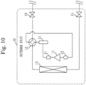
- Fig. 10 illustrates the first refrigerant path according to the present embodiment
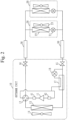
- Fig. 11 illustrates the second refrigerant path according to the present embodiment.
- the refrigerant that flows in from the indoor units 20 is returned through the gas pipe valve 16, the low-pressure sensor 42, the compressor 11, the high-pressure sensor 41, the oil separator 51, the outdoor heat exchanger 13, and the liquid pipe valve 15 to the indoor units 20.
- the first refrigerant path makes the refrigerant circulate between the outdoor unit 10 and the indoor units 20.
- the second refrigerant path is a path to make the refrigerant circulate in the outdoor unit 10.
- the second refrigerant path is a path extending through the compressor 11, the high-pressure sensor 41, the oil separator 51, the capillary tube 52, the oil return valve 53, and the low-pressure sensor 42.
- the refrigerant is allowed to circulate through the second refrigerant path by the oil return valve 53 being open even if the circulation of the refrigerant through the first refrigerant path is blocked by closure of the liquid pipe valve 15 and the gas pipe valve 16.
- the high-low pressure difference does not increase to be greater than or equal to the threshold.
- a configuration of the anomaly determination device 4 according to the present embodiment is as illustrated in Fig. 1 .
- the signal transmission unit 121 transmits to the outdoor unit 10, a command signal commanding closure of the oil return valve 53.
- the outdoor unit 10 having received the command signal closes the oil return valve 53, if the oil return valve 53 is open.
- the circulation of the refrigerant in a second refrigerant circuit is blocked by closure of the oil return valve 53.
- blockage of the circulation of the refrigerant in the second refrigerant circuit by the closure of the oil return valve 53 makes it possible for the determination unit 123 to correctly determine the state of the liquid pipe valve 15 and/or the gas pipe valve 16.
- An example of operation of the anomaly determination device 4 according to the present embodiment is as illustrated in Fig. 5 . Therefore, description of details of the operation of the anomaly determination device 4 according to the present embodiment is omitted.
- the anomaly determination device 4 is capable of correctly determining whether the liquid pipe valve 15 and/or the gas pipe valve 16 is closed or not, even though the second refrigerant path having a configuration illustrated in Fig. 11 is included in the outdoor unit 10.
- the processor 120 illustrated in Fig. 1 is an IC (Integrated Circuit) to carry out processing.
- the processor 120 is a CPU (Central Processing Unit), a DSP (Digital Signal Processor), or the like.
- the communication instrument 110 illustrated in Fig. 1 is an electronic circuit to execute communication processing for data.
- the communication instrument 110 is a communication chip or an NIC (Network Interface Card), for instance.
- an OS (Operating System) is stored in a storage device not illustrated in Fig. 1 .
- At least a portion of the OS is executed by the processor 120.
- the processor 120 executes the programs that realize the functions of the signal transmission unit 121, the operation data acquisition unit 122, the determination unit 123, and the report unit 124, while executing at least the portion of the OS.
- the processor 120 executes the OS and task management, memory management, file management, communication control, or the like is thereby carried out.
- At least any of information, data, signal values, and variable values that indicate results of processing in the signal transmission unit 121, the operation data acquisition unit 122, the determination unit 123, and the report unit 124 is stored in at least any of a storage device, and a register and a cache memory in the processor 120.
- the programs that realize the functions of the signal transmission unit 121, the operation data acquisition unit 122, the determination unit 123, and the report unit 124 may be stored in a portable storage medium such as a magnetic disc, a flexible disc, an optical disc, a compact disc, a Blu-ray (registered trademark) disc, or a DVD.
- portable storage media in which the programs that realize the functions of the signal transmission unit 121, the operation data acquisition unit 122, the determination unit 123, and the report unit 124 are stored may be distributed.
- unit of the signal transmission unit 121, the operation data acquisition unit 122, the determination unit 123, and the report unit 124 may be read as “circuit”, “step”, “procedure”, “process”, or “circuitry”.
- the anomaly determination device 4 may be implemented by a processing circuit.
- the processing circuit is a logic IC (Integrated Circuit), a GA (Gate Array), an ASIC (Application Specific Integrated Circuit), or an FPGA (Field-Programmable Gate Array), for instance.
- the signal transmission unit 121, the operation data acquisition unit 122, the determination unit 123, and the report unit 124 are each implemented as a portion of the processing circuit.
- processing circuitry a broader concept of processor and processing circuit is referred to as "processing circuitry”, herein.
- processor and processing circuit are specific examples of "processing circuitry”.
- Embodiments 1 to 3 have been described above and two or more of these embodiments may be implemented in combination.
- one of these embodiments may be partially implemented.
- two or more of these embodiments may be implemented partially in combination.
- 1 air conditioner; 2: command device; 3: display; 4: anomaly determination device; 10: outdoor unit; 11: compressor; 12: four-way valve; 13: outdoor heat exchanger; 14: outdoor unit fan; 15: liquid pipe valve; 16: gas pipe valve; 17: subcool coil; 18: expansion valve for subcool coil; 20: indoor unit; 21: expansion valve; 22: indoor heat exchanger; 23: indoor unit fan; 30: connection pipe; 41: high-pressure sensor; 42: low-pressure sensor; 51: oil separator; 52: capillary tube; 53: oil return valve; 110: communication instrument; 111: injection compressor; 117: economizer; 118: expansion valve for injection; 119: injection pipe; 120: processor; 121: signal transmission unit; 122: operation data acquisition unit; 123: determination unit; 124: report unit
Landscapes
- Engineering & Computer Science (AREA)
- Physics & Mathematics (AREA)
- Mechanical Engineering (AREA)
- Thermal Sciences (AREA)
- General Engineering & Computer Science (AREA)
- Air Conditioning Control Device (AREA)
Abstract
Description
- The present disclosure relates to a technique of inspecting whether a valve provided in a refrigerant path of an air conditioner is closed or not.
- A liquid pipe valve and a gas pipe valve are placed in inlet and outlet portions of a refrigerant path (to be referred to below as a first refrigerant path) to circulate refrigerant between an outdoor unit and an outdoor unit of an air conditioner. Hereinbelow, the liquid pipe valve and the gas pipe valve are also referred to collectively as a first valve.
- When an air conditioner is installed, commonly, commissioning of the air conditioner is carried out and absence of inadequacy in installation work is checked.
- The first valve needs to be brought into an open state by an operator when the air conditioner is installed. When the first valve is in a closed state or when the first valve is not fully opened, the first refrigerant path is blocked so that the refrigerant is not circulated. Accordingly, it is assumed that an expected air conditioning capability is not fulfilled. Otherwise, it is assumed that power consumption may increase with increase in pressure loss.
- Further, when the first valve is in the closed state, a pressure difference between a low pressure (inlet pressure) and a high pressure (discharge pressure) may increase, so that the air conditioner may be stopped due to protective control for protection of the air conditioner. When the air conditioner is stopped in this manner, the operator needs to examine a cause of stoppage. Meanwhile, when operation of the air conditioner continues in spite of the protective control, the operator needs to avoid overlooking the first valve in the closed state.
- Thus, detecting the closed state of the first valve and making the operator recognize that the first valve is in the closed state are required in the commissioning of the air conditioner following the installation, in particular.
- From such a viewpoint, a technique of detecting whether the first valve is in the closed state or not is disclosed in Patent Literature 1.
- Patent Literature 1:
JP 2007-107820 - In some outdoor units, there may be a second refrigerant path that enables circulation of the refrigerant in the outdoor unit even if the circulation of the refrigerant through the first refrigerant path is blocked by closure of the first valve. In such an outdoor unit, the pressure difference between the low pressure and the high pressure does not increase even if the first valve is closed, because the refrigerant is circulated through the second refrigerant path. Therefore, the technique of Patent Literature 1 has a problem in that it may be incorrectly determined that the first valve is open though the first valve is closed.
- The present disclosure mainly aims at solving such a problem. More specifically, the present disclosure mainly aims at making it possible to correctly determine whether the first valve is closed or not even if an outdoor unit in which the second refrigerant path exists is used.
- An inspection device according to the present disclosure includes:
- a signal transmission unit, when there exists in an outdoor unit a second refrigerant path which enables circulation of refrigerant in the outdoor unit even if circulation of the refrigerant through a first refrigerant path is blocked by closure of a first valve provided in the first refrigerant path which circulates the refrigerant between an indoor unit and the outdoor unit of an air conditioner, to transmit to the outdoor unit, a command signal commanding the outdoor unit to close a second valve which is provided in the second refrigerant path and closure of which blocks the circulation of the refrigerant through the second refrigerant path; and
- a determination unit to determine whether the first valve is closed or not after the command signal is transmitted from the signal transmission unit to the outdoor unit.
- According to the present disclosure, it can be correctly determined whether the first valve is closed or not even if the outdoor unit in which the second refrigerant path exists is used.
-
-
Fig. 1 is a diagram illustrating a configuration example of an anomaly detection system according to Embodiment 1. -
Fig. 2 is a diagram illustrating a configuration example of an air conditioner according to Embodiment 1. -
Fig. 3 is a diagram illustrating a first refrigerant path according to Embodiment 1. -
Fig. 4 is a diagram illustrating a second refrigerant path according to Embodiment 1. -
Fig. 5 is a flowchart illustrating an example of operation of an anomaly determination device according to Embodiment 1. -
Fig. 6 is a diagram illustrating a configuration example of an air conditioner according to Embodiment 2. -
Fig. 7 is a diagram illustrating a first refrigerant path according to Embodiment 2. -
Fig. 8 is a diagram illustrating a second refrigerant path according to Embodiment 2. -
Fig. 9 is a diagram illustrating a configuration example of an air conditioner according to Embodiment 3. -
Fig. 10 is a diagram illustrating a first refrigerant path according to Embodiment 3. -
Fig. 11 is a diagram illustrating a second refrigerant path according to Embodiment 3. - Hereinbelow, embodiments will be described with use of the drawings. In following description on the embodiments and the drawings, elements provided with identical reference numerals represent identical parts or corresponding parts.
-
Fig. 1 illustrates a configuration example of an anomaly detection system according to the present embodiment. - The anomaly detection system includes an air conditioner 1, a command device 2, a display 3, and an anomaly determination device 4.
- The air conditioner 1, the command device 2, and the display 3 are connected to the anomaly determination device 4.
- The command device 2 commands the air conditioner 1 to start commissioning. The command device 2 is a remote controller for the air conditioner 1 or a PC (Personal Computer) connected to the air conditioner 1, for instance.
- When a closed state of a
liquid pipe valve 15 and/or agas pipe valve 16 that will be described later is detected, the display 3 displays a message making notification that theliquid pipe valve 15 and/or thegas pipe valve 16 is in the closed state. Display of the message by the display 3 makes it possible for an operator who does installation work for the air conditioner 1 to recognize that theliquid pipe valve 15 and/or thegas pipe valve 16 is in the closed state. - The display 3 is a remote controller for the air conditioner 1 or a PC connected to the air conditioner 1, for instance.
- The command device 2 and the display 3 may be implemented as the same device.
- The anomaly determination device 4 is a computer. If the command device 2 and/or the display 3 is implemented by the PC, the anomaly determination device 4 may be implemented by the same PC as the command device 2 and/or the display 3.
- The anomaly determination device 4 includes a
communication instrument 110 and aprocessor 120. Further, a storage device such as a RAM (Random Access Memory) or an HDD (Hard Disk Drive) is supposed to be included in the anomaly determination device 4, though not illustrated. - The
communication instrument 110 communicates with the air conditioner 1, the command device 2, and the display 3. - The
processor 120 executes programs that realize functions of asignal transmission unit 121, an operationdata acquisition unit 122, adetermination unit 123, and areport unit 124. Theprocessor 120 executes the programs to function as thesignal transmission unit 121, the operationdata acquisition unit 122, thedetermination unit 123, and thereport unit 124. Details of thesignal transmission unit 121, the operationdata acquisition unit 122, thedetermination unit 123, and thereport unit 124 will be described later. - Incidentally, the anomaly determination device 4 is equivalent to an inspection device. Further, an operation procedure of the anomaly determination device 4 is equivalent to an inspection method.
-
Fig. 2 illustrates a configuration example of the air conditioner 1. - The air conditioner 1 includes an
outdoor unit 10,indoor units 20, andconnection pipes 30 to connect theoutdoor unit 10 and theindoor units 20. -
Fig. 2 illustrates a configuration in which the plurality ofindoor units 20 are connected to the oneoutdoor unit 10. The configuration of the air conditioner 1, however, is not limited to that illustrated inFig. 2 . The air conditioner 1 may have a configuration in which oneindoor unit 20 is connected to the oneoutdoor unit 10. Alternatively, a plurality ofoutdoor units 10 may be included in the air conditioner 1. - The
outdoor unit 10 includes acompressor 11, a four-way valve 12, anoutdoor heat exchanger 13, anoutdoor unit fan 14, theliquid pipe valve 15, thegas pipe valve 16, asubcool coil 17, and anexpansion valve 18 for subcool coil. - The
indoor units 20 each include anexpansion valve 21, anindoor heat exchanger 22, and anindoor unit fan 23. - A refrigeration cycle is configured by ring-like connection of the
compressor 11, the four-way valve 12, theoutdoor heat exchanger 13, theexpansion valve 21, and theindoor heat exchanger 22 through refrigerant pipes. - Incidentally, the
outdoor unit 10 includes a communication instrument to receive a command signal from the anomaly determination device 4, though not illustrated inFig. 2 . Further, theoutdoor unit 10 includes a valve control mechanism to close theexpansion valve 18 for subcool coil based on the command signal. The command signal is a signal by which the anomaly determination device 4 commands theoutdoor unit 10 to close theexpansion valve 18 for subcool coil. - The
compressor 11 compresses refrigerant having a low temperature and a low pressure and thereby converts the refrigerant having the low temperature and the low pressure into the refrigerant having a high temperature and a high pressure. Thecompressor 11 is driven by an inverter, for instance, and has a controlled capacity (amount of the refrigerant to be discharged per unit time). - The four-
way valve 12 switches flow of the refrigerant, in accordance with an operation mode of the air conditioner 1, such as cooling operation or heating operation. - The
outdoor heat exchanger 13 carries out heat exchange between the refrigerant flowing through the refrigeration cycle and outdoor air. Theoutdoor unit fan 14 adjoins theoutdoor heat exchanger 13. - The
outdoor unit fan 14 blows air against theoutdoor heat exchanger 13. An amount of the blown air can be adjusted by control over the number of revolutions of theoutdoor unit fan 14. - The
expansion valve 21 includes a valve whose opening can be variably controlled, such as an electronic expansion valve. A pressure reduction amount for the refrigerant is controlled by control over the opening of theexpansion valve 21. - The
indoor heat exchanger 22 carries out heat exchange between the refrigerant flowing through the refrigeration cycle and indoor air. Theindoor unit fan 23 adjoins theindoor heat exchanger 22. - The
indoor unit fan 23 blows air against theindoor heat exchanger 22. An amount of the blown air can be adjusted by control over the number of revolutions of theindoor unit fan 23. - A high-
pressure sensor 41 and a low-pressure sensor 42 are installed ahead and behind thecompressor 11 of theoutdoor unit 10. The high-pressure sensor 41 measures a high pressure value (discharge pressure value) of the refrigerant in thecompressor 11. The low-pressure sensor 42 measures a low pressure value (inlet pressure value) of the refrigerant in thecompressor 11. - The high-
pressure sensor 41 and the low-pressure sensor 42 are used when control for making the high pressure and the low pressure close to target values is exerted. Further, the high-pressure sensor 41 and the low-pressure sensor 42 are used for protective control for preventing theoutdoor unit 10 from being damaged by increase in the high pressure and decrease in the low pressure. - The
liquid pipe valve 15 and thegas pipe valve 16 are provided in connection portions between theoutdoor unit 10 and theconnection pipes 30. - The operator who does the installation work installs the air conditioner 1 by connecting the
outdoor unit 10, theindoor units 20, and theconnection pipes 30 at an installation site. During shipment and transfer, theliquid pipe valve 15 and thegas pipe valve 16 are closed. After theoutdoor unit 10, theindoor units 20, and theconnection pipes 30 are connected at the installation site, the operator opens theliquid pipe valve 15 and thegas pipe valve 16. Opening theliquid pipe valve 15 and thegas pipe valve 16 enables circulation of the refrigerant. - The
liquid pipe valve 15 and thegas pipe valve 16 are equivalent to first valves. - In the cooling operation, degree of undercooling can be increased by reduction in pressure of a portion of the refrigerant, having gone out of the
outdoor heat exchanger 13 and having a high pressure, by theexpansion valve 18 for subcool coil and heat exchange in thesubcool coil 17 between the refrigerant reduced in the pressure and the refrigerant before diverging. The refrigerant reduced in the pressure is returned to thecompressor 11. - The
expansion valve 18 for subcool coil is equivalent to a second valve. - In the
outdoor unit 10 illustrated inFig. 2 , two refrigerant paths to circulate the refrigerant exist. -
Figs. 3 and4 illustrate the two refrigerant paths existing in theoutdoor unit 10. -
Fig. 3 illustrates a first refrigerant path andFig. 4 illustrates a second refrigerant path. - In the first refrigerant path of
Fig. 3 , the refrigerant that flows in from theindoor units 20 is returned through thegas pipe valve 16, the low-pressure sensor 42, thecompressor 11, the high-pressure sensor 41, theoutdoor heat exchanger 13, thesubcool coil 17, and theliquid pipe valve 15 to theindoor units 20. The first refrigerant path makes the refrigerant circulate between theoutdoor unit 10 and theindoor units 20. - The second refrigerant path of
Fig. 4 is a path to make the refrigerant circulate in theoutdoor unit 10. That is, the second refrigerant path is a path extending through theoutdoor heat exchanger 13, thesubcool coil 17, theexpansion valve 18 for subcool coil, the low-pressure sensor 42, thecompressor 11, and the high-pressure sensor 41. - In a case where either or both of the
liquid pipe valve 15 and thegas pipe valve 16 are closed in a configuration in which the second refrigerant path does not exist, a high-low pressure difference increases when thecompressor 11 operates, compared with a case where both the valves are normally open. When the high-low pressure difference exceeds a predetermined threshold, it can be determined that theliquid pipe valve 15 and/or thegas pipe valve 16 may be in the closed state. - In the configuration in which the second refrigerant path exists, however, the refrigerant is allowed to circulate through the second refrigerant path by the
expansion valve 18 for subcool coil being open even if the circulation of the refrigerant through the first refrigerant path is blocked by closure of theliquid pipe valve 15 and thegas pipe valve 16. When the refrigerant circulates through the second refrigerant path even though theliquid pipe valve 15 and thegas pipe valve 16 are closed, the high-low pressure difference does not increase to be greater than or equal to the threshold. Thus, there is a problem of failing to correctly determine a state of theliquid pipe valve 15 and/or thegas pipe valve 16 when theexpansion valve 18 for subcool coil is open. - In regard to such a problem, the anomaly determination device 4 according to the present embodiment has a configuration that enables correctly determining whether the
liquid pipe valve 15 and/or thegas pipe valve 16 is closed or not even though the second refrigerant path exists in theoutdoor unit 10. - Hereinbelow, the configuration of the anomaly determination device 4 according to the present embodiment will be described.
- The
signal transmission unit 121 transmits a command signal to theoutdoor unit 10 in the commissioning of the air conditioner 1. The command signal is a signal that commands closure of theexpansion valve 18 for subcool coil. - The
outdoor unit 10 having received the command signal closes theexpansion valve 18 for subcool coil, if theexpansion valve 18 for subcool coil is open. The circulation of the refrigerant in a second refrigerant circuit is blocked by closure of theexpansion valve 18 for subcool coil. - Blockage of the circulation of the refrigerant in the second refrigerant circuit by the closure of the
expansion valve 18 for subcool coil makes it possible for thedetermination unit 123 that will be described later to correctly determine the state of theliquid pipe valve 15 and/or thegas pipe valve 16. - The operation
data acquisition unit 122 acquires operation data on the air conditioner 1. The operation data is sensor values obtained from a sensor provided in the air conditioner 1, for instance. Further, the operation data is controlling values for the air conditioner 1. In the sensor values, the high pressure value measured by the high-pressure sensor 41 and the low pressure value measured by the low-pressure sensor 42 are included. In the controlling values, such values as a frequency of thecompressor 11, the number of revolutions of theoutdoor unit fan 14, and the valve opening of theexpansion valve 21 are included. - The operation
data acquisition unit 122 acquires the high pressure value measured by the high-pressure sensor 41 and the low pressure value measured by the low-pressure sensor 42 after transmission of the command signal from thesignal transmission unit 121. - The
determination unit 123 determines whether theliquid pipe valve 15 and/or thegas pipe valve 16 is in the closed state or not, based on the high pressure value and the low pressure value acquired as the operation data by the operationdata acquisition unit 122. As described above, thedetermination unit 123 determines that theliquid pipe valve 15 and/or thegas pipe valve 16 is in the closed state, when the high-low pressure difference which is the pressure difference between the high pressure value and the low pressure value exceeds the threshold. - Alternatively, the
determination unit 123 may determine that theliquid pipe valve 15 and/or thegas pipe valve 16 is in the closed state, when the high pressure exceeds a predetermined threshold. Meanwhile, thedetermination unit 123 may determine that theliquid pipe valve 15 and/or thegas pipe valve 16 is in the closed state, when the low pressure is lower than a predetermined threshold. - Further, the
determination unit 123 may determine that theliquid pipe valve 15 and/or thegas pipe valve 16 is in the closed state, when operation of the air conditioner 1 is stopped by exercise of the protective function due to increase in the high pressure or decrease in the low pressure. - In a case where it is determined by the
determination unit 123 that theliquid pipe valve 15 and/or thegas pipe valve 16 is in the closed state, thereport unit 124 reports to the operator that theliquid pipe valve 15 and/or thegas pipe valve 16 is in the closed state. Specifically, thereport unit 124 outputs to the display 3, a message of notification that theliquid pipe valve 15 and/or thegas pipe valve 16 is in the closed state. -
Fig. 5 illustrates an example of operation of the anomaly determination device 4 according to the present embodiment. Hereinbelow, the operation of the anomaly determination device 4 according to the present Embodiment 1 will be described with reference to a flow ofFig. 5 . - Upon a command from the command device 2 to start the commissioning of the air conditioner 1, the commissioning of the air conditioner 1 is started. Once the commissioning of the air conditioner 1 is started, the operation
data acquisition unit 122 acquires the controlling values as the operation data and recognizes the start of the commissioning of the air conditioner 1. - Subsequently, in step ST01, the
signal transmission unit 121 transmits the command signal to theoutdoor unit 10. Theoutdoor unit 10 having received the command signal closes theexpansion valve 18 for subcool coil, based on the command signal. - In step ST02, the operation
data acquisition unit 122 acquires the high pressure value from the high-pressure sensor 41. Further, the operationdata acquisition unit 122 acquires the low pressure value from the low-pressure sensor 42. Further, thedetermination unit 123 calculates the high-low pressure difference ΔP (high pressure value minus low pressure value) that is the difference between the high pressure value and the low pressure value. - Subsequently, in step ST03, the
determination unit 123 determines whether the high-low pressure difference ΔP exceeds the predetermined threshold or not. - When the high-low pressure difference ΔP exceeds the threshold, processing proceeds to step ST04. On the other hand, when the high-low pressure difference ΔP is smaller than or equal to the threshold, the processing is ended.
- In step ST04, the
determination unit 123 determines that theliquid pipe valve 15 and/or thegas pipe valve 16 is in the closed state. Then, thereport unit 124 outputs to the display 3, the message of notification that theliquid pipe valve 15 and/or thegas pipe valve 16 is in the closed state. The display 3 displays the message of the notification that theliquid pipe valve 15 and/or thegas pipe valve 16 is in the closed state. - The operator having looked at the message displayed by the display 3 checks the
liquid pipe valve 15 and thegas pipe valve 16 and, if theliquid pipe valve 15 and/or thegas pipe valve 16 is in the closed state, does opening work for theliquid pipe valve 15 and/or thegas pipe valve 16. - Incidentally, in regard to step ST03, the
determination unit 123 may make a comparison between the high pressure value and the threshold instead of a comparison between the high-low pressure difference ΔP and the threshold, as described above. When the high pressure value then exceeds the threshold, thedetermination unit 123 determines that theliquid pipe valve 15 and/or thegas pipe valve 16 is in the closed state. In step ST02, in this case, it is sufficient if the operationdata acquisition unit 122 acquires only the high pressure value and thedetermination unit 123 does not need to calculate the high-low pressure difference ΔP. - Alternatively, in regard to step ST03, the
determination unit 123 may make a comparison between the low pressure value and the threshold instead of a comparison between the high-low pressure difference ΔP and the threshold, as described above. When the low pressure value is then less than the threshold, thedetermination unit 123 determines that theliquid pipe valve 15 and/or thegas pipe valve 16 is in the closed state. In step ST02, in this case, it is sufficient if the operationdata acquisition unit 122 acquires only the low pressure value and thedetermination unit 123 does not need to calculate the high-low pressure difference ΔP. - Alternatively, in regard to step ST03, the
determination unit 123 may make a determination of whether the operation of the air conditioner 1 is stopped or not by the exercise of the protective function due to the increase in the high pressure or the decrease in the low pressure, instead of the comparison between the high-low pressure difference ΔP and the threshold, as described above. When the operation of the air conditioner 1 is then stopped by the exercise of the protective function due to the increase in the high pressure or the decrease in the low pressure, thedetermination unit 123 may determine that theliquid pipe valve 15 and/or thegas pipe valve 16 is in the closed state. In this case, the operationdata acquisition unit 122 acquires the controlling values representing stoppage of the operation of the air conditioner 1, as the operation data, in step ST02. Then, thedetermination unit 123 analyzes the controlling values and recognizes that the operation of the air conditioner 1 is stopped by the exercise of the protective function due to the increase in the high pressure or the decrease in the low pressure. - Further, the threshold to be compared with the high-low pressure difference ΔP may be a fixed value or may be a variable value. In a case where the variable threshold is used, it is conceived that the
determination unit 123 changes the threshold in accordance with an operating condition of the air conditioner 1, such as the frequency of thecompressor 11 or the opening of theexpansion valve 21 of theindoor unit 20. Detection accuracy under a condition that theliquid pipe valve 15 and/or thegas pipe valve 16 is not fully-closed can be improved by such change in the threshold in accordance with the operating condition by thedetermination unit 123. - Further, when the high pressure value is compared with the threshold instead of the high-low pressure difference ΔP, the
determination unit 123 may use a variable threshold that changes in accordance with the operating condition of the air conditioner 1, as the threshold to be compared with the high pressure value. - Similarly, when the low pressure value is compared with the threshold instead of the high-low pressure difference ΔP, the
determination unit 123 may use a variable threshold that changes in accordance with the operating condition of the air conditioner 1, as the threshold to be compared with the low pressure value. - Further, above description presupposes that the operator having looked at the message displayed by the display 3 does the opening work for the
liquid pipe valve 15 and/or thegas pipe valve 16. - Alternatively, the anomaly determination device 4 may command opening of the
liquid pipe valve 15 and/or thegas pipe valve 16 to theoutdoor unit 10, so that theliquid pipe valve 15 and/or thegas pipe valve 16 may be automatically opened. In this case, theoutdoor unit 10 is supposed to include the valve control mechanism, not illustrated inFig. 2 , to control opening and closure of theliquid pipe valve 15 and thegas pipe valve 16. - Specifically, in a case where it is determined by the
determination unit 123 that theliquid pipe valve 15 and/or thegas pipe valve 16 is closed, thesignal transmission unit 121 transmits to theoutdoor unit 10, a command signal commanding the opening of theliquid pipe valve 15 and/or thegas pipe valve 16. Theoutdoor unit 10 having received the command signal opens theliquid pipe valve 15 and/or thegas pipe valve 16 through control over the valve control mechanism. - A work burden on the operator can be relieved by such automatic opening of the
liquid pipe valve 15 and/or thegas pipe valve 16. Incidentally, in this case, output of the message to the display 3 by thereport unit 124 may be omitted. - In the present embodiment, as described above, the anomaly determination device 4 transmits to the
outdoor unit 10, the command signal commanding the closure of theexpansion valve 18 for subcool coil, and theoutdoor unit 10 closes theexpansion valve 18 for subcool coil. According to the present embodiment, therefore, the anomaly determination device 4 is capable of correctly determining whether theliquid pipe valve 15 and/or thegas pipe valve 16 is closed or not even though the second refrigerant path exists in theoutdoor unit 10. As a result, the operator can be notified in the commissioning that theliquid pipe valve 15 and/or thegas pipe valve 16 is in the closed state even if the operator forgets to open theliquid pipe valve 15 and/or thegas pipe valve 16 in the installation work. Further, shortening of working hours is facilitated because, even if abnormal stoppage occurs in the commissioning, the operator can recognize that the abnormal stoppage has been caused by the closure of theliquid pipe valve 15 and/or thegas pipe valve 16. - In Embodiment 1, the
outdoor unit 10 having the configuration illustrated inFig. 2 , that is, theoutdoor unit 10 including thesubcool coil 17 and theexpansion valve 18 for subcool coil and including the second refrigerant path illustrated inFig. 4 has been described. - In the present embodiment, the
outdoor unit 10 having another configuration will be described. - As for the present embodiment, differences from Embodiment 1 will be principally described.
- Incidentally, particulars that will not be described below are similar to particulars of Embodiment 1.
-
Fig. 6 illustrates a configuration example of the air conditioner 1 according to the present embodiment. - The
indoor units 20 and theconnection pipes 30 are the same as those illustrated inFig. 2 and description thereof is therefore omitted. - Further, the four-
way valve 12, theoutdoor heat exchanger 13, theoutdoor unit fan 14, theliquid pipe valve 15, thegas pipe valve 16, the high-pressure sensor 41, and the low-pressure sensor 41 in theoutdoor unit 10 are the same as those illustrated inFig. 2 and description thereof is therefore omitted. - In the
outdoor unit 10 illustrated inFig. 6 , aninjection compressor 111 is provided in place of thecompressor 11 illustrated inFig. 2 . Theinjection compressor 111 has a connection opening for intermediate pressure in addition to a connection opening for discharge pressure and a connection opening for inlet pressure. - Further, in the
outdoor unit 10 illustrated inFig. 6 , anexpansion valve 118 for injection is provided in place of theexpansion valve 18 for subcool coil illustrated inFig. 2 . Theexpansion valve 118 for injection adjusts an injection amount to be injected from aninjection pipe 119 into the intermediate pressure of theinjection compressor 111. Theexpansion valve 118 for injection is equivalent to the second valve. - Further, in the
outdoor unit 10 illustrated inFig. 6 , aneconomizer 117 is provided in place of thesubcool coil 17 illustrated inFig. 2 . Theeconomizer 117 recovers heat from liquid refrigerant having flowed out of theoutdoor heat exchanger 13, by the refrigerant with the intermediate pressure. - In the
outdoor unit 10 illustrated inFig. 6 , refrigeration cycle efficiency can be improved in the cooling operation by diverging of a portion of the liquid refrigerant having flowed out of theoutdoor heat exchanger 13 and injection thereof into the intermediate pressure of theinjection compressor 111. - Incidentally, the
outdoor unit 10 is supposed to include a valve control mechanism that is not illustrated inFig. 6 and that is to close theexpansion valve 118 for injection based on a command signal. - In the
outdoor unit 10 according to the present embodiment as well, a first refrigerant path and a second refrigerant path exist. -
Fig. 7 illustrates the first refrigerant path according to the present embodiment, andFig. 8 illustrates the second refrigerant path according to the present embodiment. - In the first refrigerant path of
Fig. 7 , the refrigerant that flows in from theindoor units 20 is returned through thegas pipe valve 16, the low-pressure sensor 42, theinjection compressor 111, the high-pressure sensor 41, theoutdoor heat exchanger 13, theeconomizer 117, and theliquid pipe valve 15 to theindoor units 20. The first refrigerant path makes the refrigerant circulate between theoutdoor unit 10 and theindoor units 20. - In the present embodiment as well, the second refrigerant path is a path to make the refrigerant circulate in the
outdoor unit 10. In the present embodiment, as illustrated inFig. 8 , the second refrigerant path is a path extending through theoutdoor heat exchanger 13, theeconomizer 117, theexpansion valve 118 for injection, theinjection pipe 119, theinjection compressor 111, and the high-pressure sensor 41. - In the
outdoor unit 10 according to the present embodiment as well, the refrigerant is allowed to circulate through the second refrigerant path by theexpansion valve 118 for injection being open even if the circulation of the refrigerant through the first refrigerant path is blocked by closure of theliquid pipe valve 15 and thegas pipe valve 16. When the refrigerant circulates through the second refrigerant path even though theliquid pipe valve 15 and thegas pipe valve 16 are closed, the high-low pressure difference does not increase to be greater than or equal to the threshold. Thus, there is a problem of failing to correctly determine a state of theliquid pipe valve 15 and/or thegas pipe valve 16 when theexpansion valve 118 for injection is open. - A configuration of the anomaly determination device 4 according to the present embodiment is as illustrated in
Fig. 1 . - In the present embodiment as well, for solution of the above problem, the
signal transmission unit 121 transmits to theoutdoor unit 10, a command signal commanding closure of theexpansion valve 118 for injection. - The
outdoor unit 10 having received the command signal closes theexpansion valve 118 for injection, if theexpansion valve 118 for injection is open. The circulation of the refrigerant in a second refrigerant circuit is blocked by closure of theexpansion valve 118 for injection. - In the present embodiment as well, blockage of the circulation of the refrigerant in the second refrigerant circuit by the closure of the
expansion valve 118 for injection makes it possible for thedetermination unit 123 to correctly determine the state of theliquid pipe valve 15 and/or thegas pipe valve 16. - An example of operation of the anomaly determination device 4 according to the present embodiment is as illustrated in
Fig. 5 . Therefore, description of details of the operation of the anomaly determination device 4 according to the present embodiment is omitted. - Thus, the anomaly determination device 4 is capable of correctly determining whether the
liquid pipe valve 15 and/or thegas pipe valve 16 is closed or not, even though the second refrigerant path having a configuration illustrated inFig. 8 is included in theoutdoor unit 10. - In the present embodiment, the
outdoor unit 10 having a configuration differing from configurations of Embodiment 1 and Embodiment 2 will be described. - As for the present embodiment, differences from Embodiment 1 will be principally described.
- Incidentally, particulars that will not be described below are similar to particulars of Embodiment 1.
-
Fig. 9 illustrates a configuration example of the air conditioner 1 according to the present embodiment. - The
indoor units 20 and theconnection pipes 30 are the same as those illustrated inFig. 2 and description thereof is therefore omitted. - Further, the
compressor 11, the four-way valve 12, theoutdoor heat exchanger 13, theoutdoor unit fan 14, theliquid pipe valve 15, thegas pipe valve 16, the high-pressure sensor 41, and the low-pressure sensor 42 in theoutdoor unit 10 are the same as those illustrated inFig. 2 and description thereof is therefore omitted. - In the
outdoor unit 10 according to the present embodiment, anoil separator 51, acapillary tube 52, and anoil return valve 53 are provided. - The
oil separator 51 separates refrigerant oil included in the refrigerant discharged from thecompressor 11. - The
capillary tube 52 functions as a flow path resistance for adequate adjustment in flow rates of the refrigerant oil and the refrigerant to be returned from theoil separator 51 to an inlet side of thecompressor 11. - The
oil return valve 53 is opened during operation of thecompressor 11. Theoil return valve 53 is equivalent to the second valve. - The refrigerant oil discharged from the
compressor 11 is quickly recovered into thecompressor 11 through an oil return path including theoil separator 51, thecapillary tube 52, and theoil return valve 53. Thus, distribution throughout the refrigerant path of the refrigerant oil having flowed out of theoutdoor unit 10, which may result in poor lubrication of thecompressor 11, can be prevented. As a result, a refrigeration cycle that is highly reliable can be implemented. - Incidentally, the
outdoor unit 10 is supposed to include a valve control mechanism that is not illustrated inFig. 9 and that is to close theoil return valve 53 based on a command signal. - In the
outdoor unit 10 according to the present embodiment as well, a first refrigerant path and a second refrigerant path exist. -
Fig. 10 illustrates the first refrigerant path according to the present embodiment, andFig. 11 illustrates the second refrigerant path according to the present embodiment. - In the first refrigerant path of
Fig. 10 , the refrigerant that flows in from theindoor units 20 is returned through thegas pipe valve 16, the low-pressure sensor 42, thecompressor 11, the high-pressure sensor 41, theoil separator 51, theoutdoor heat exchanger 13, and theliquid pipe valve 15 to theindoor units 20. The first refrigerant path makes the refrigerant circulate between theoutdoor unit 10 and theindoor units 20. - In the present embodiment as well, the second refrigerant path is a path to make the refrigerant circulate in the
outdoor unit 10. In the present embodiment, as illustrated inFig. 11 , the second refrigerant path is a path extending through thecompressor 11, the high-pressure sensor 41, theoil separator 51, thecapillary tube 52, theoil return valve 53, and the low-pressure sensor 42. - In the
outdoor unit 10 according to the present embodiment as well, the refrigerant is allowed to circulate through the second refrigerant path by theoil return valve 53 being open even if the circulation of the refrigerant through the first refrigerant path is blocked by closure of theliquid pipe valve 15 and thegas pipe valve 16. When the refrigerant circulates through the second refrigerant path even though theliquid pipe valve 15 and thegas pipe valve 16 are closed, the high-low pressure difference does not increase to be greater than or equal to the threshold. Thus, there is a problem of failing to correctly determine a state of theliquid pipe valve 15 and/or thegas pipe valve 16 when theoil return valve 53 is open. - A configuration of the anomaly determination device 4 according to the present embodiment is as illustrated in
Fig. 1 . - In the present embodiment as well, for solution of the above problem, the
signal transmission unit 121 transmits to theoutdoor unit 10, a command signal commanding closure of theoil return valve 53. - The
outdoor unit 10 having received the command signal closes theoil return valve 53, if theoil return valve 53 is open. The circulation of the refrigerant in a second refrigerant circuit is blocked by closure of theoil return valve 53. - In the present embodiment as well, blockage of the circulation of the refrigerant in the second refrigerant circuit by the closure of the
oil return valve 53 makes it possible for thedetermination unit 123 to correctly determine the state of theliquid pipe valve 15 and/or thegas pipe valve 16. - An example of operation of the anomaly determination device 4 according to the present embodiment is as illustrated in
Fig. 5 . Therefore, description of details of the operation of the anomaly determination device 4 according to the present embodiment is omitted. - Thus, the anomaly determination device 4 is capable of correctly determining whether the
liquid pipe valve 15 and/or thegas pipe valve 16 is closed or not, even though the second refrigerant path having a configuration illustrated inFig. 11 is included in theoutdoor unit 10. - Lastly, supplementary description of a hardware configuration of the anomaly determination device 4 will be given.
- The
processor 120 illustrated inFig. 1 is an IC (Integrated Circuit) to carry out processing. - The
processor 120 is a CPU (Central Processing Unit), a DSP (Digital Signal Processor), or the like. - The
communication instrument 110 illustrated inFig. 1 is an electronic circuit to execute communication processing for data. - The
communication instrument 110 is a communication chip or an NIC (Network Interface Card), for instance. - Further, an OS (Operating System) is stored in a storage device not illustrated in
Fig. 1 . - At least a portion of the OS is executed by the
processor 120. - The
processor 120 executes the programs that realize the functions of thesignal transmission unit 121, the operationdata acquisition unit 122, thedetermination unit 123, and thereport unit 124, while executing at least the portion of the OS. - The
processor 120 executes the OS and task management, memory management, file management, communication control, or the like is thereby carried out. - At least any of information, data, signal values, and variable values that indicate results of processing in the
signal transmission unit 121, the operationdata acquisition unit 122, thedetermination unit 123, and thereport unit 124 is stored in at least any of a storage device, and a register and a cache memory in theprocessor 120. - Further, the programs that realize the functions of the
signal transmission unit 121, the operationdata acquisition unit 122, thedetermination unit 123, and thereport unit 124 may be stored in a portable storage medium such as a magnetic disc, a flexible disc, an optical disc, a compact disc, a Blu-ray (registered trademark) disc, or a DVD. Moreover, portable storage media in which the programs that realize the functions of thesignal transmission unit 121, the operationdata acquisition unit 122, thedetermination unit 123, and thereport unit 124 are stored may be distributed. - Further, "unit" of the
signal transmission unit 121, the operationdata acquisition unit 122, thedetermination unit 123, and thereport unit 124 may be read as "circuit", "step", "procedure", "process", or "circuitry". - Further, the anomaly determination device 4 may be implemented by a processing circuit. The processing circuit is a logic IC (Integrated Circuit), a GA (Gate Array), an ASIC (Application Specific Integrated Circuit), or an FPGA (Field-Programmable Gate Array), for instance.
- In this case, the
signal transmission unit 121, the operationdata acquisition unit 122, thedetermination unit 123, and thereport unit 124 are each implemented as a portion of the processing circuit. - Incidentally, a broader concept of processor and processing circuit is referred to as "processing circuitry", herein.
- That is, processor and processing circuit are specific examples of "processing circuitry".
- Embodiments 1 to 3 have been described above and two or more of these embodiments may be implemented in combination.
- Alternatively, one of these embodiments may be partially implemented.
- Alternatively, two or more of these embodiments may be implemented partially in combination.
- Further, the configurations and procedures described as to these embodiments may be modified as appropriate.
- 1: air conditioner; 2: command device; 3: display; 4: anomaly determination device; 10: outdoor unit; 11: compressor; 12: four-way valve; 13: outdoor heat exchanger; 14: outdoor unit fan; 15: liquid pipe valve; 16: gas pipe valve; 17: subcool coil; 18: expansion valve for subcool coil; 20: indoor unit; 21: expansion valve; 22: indoor heat exchanger; 23: indoor unit fan; 30: connection pipe; 41: high-pressure sensor; 42: low-pressure sensor; 51: oil separator; 52: capillary tube; 53: oil return valve; 110: communication instrument; 111: injection compressor; 117: economizer; 118: expansion valve for injection; 119: injection pipe; 120: processor; 121: signal transmission unit; 122: operation data acquisition unit; 123: determination unit; 124: report unit
Claims (8)
- An inspection device comprising:a signal transmission unit, when there exists in an outdoor unit a second refrigerant path which enables circulation of refrigerant in the outdoor unit even if circulation of the refrigerant through a first refrigerant path is blocked by closure of a first valve provided in the first refrigerant path which circulates the refrigerant between an indoor unit and the outdoor unit of an air conditioner, to transmit to the outdoor unit, a command signal commanding the outdoor unit to close a second valve which is provided in the second refrigerant path and closure of which blocks the circulation of the refrigerant through the second refrigerant path; anda determination unit to determine whether the first valve is closed or not after the command signal is transmitted from the signal transmission unit to the outdoor unit.
- The inspection device according to claim 1, wherein
the determination unit determines whether the first valve is closed or not with use of at least either of a high pressure value and a low pressure value of the refrigerant in a compressor included in the outdoor unit. - The inspection device according to claim 2, wherein
the determination unit determines whether the first valve is closed or not by comparing any of the high pressure value, the low pressure value, and a pressure difference between the high pressure value and the low pressure value with a variable threshold that changes in accordance with an operating condition of the air conditioner. - The inspection device according to claim 1, wherein
when it is determined by the determination unit that the first valve is closed, the signal transmission unit transmits to the outdoor unit, a command signal commanding opening of the first valve. - The inspection device according to claim 1, wherein
the second refrigerant path is a refrigerant path in which a subcool coil is included and in which an expansion valve for subcool coil is provided as the second valve. - The inspection device according to claim 1, wherein
the second refrigerant path is a refrigerant circuit in which an economizer is included and in which an expansion valve for injection for adjustment of an injection amount to be injected into an injection compressor included in the outdoor unit is provided as the second valve. - The inspection device according to claim 1, wherein
the second refrigerant path is a refrigerant circuit which includes an oil separator to separate refrigerant oil included in the refrigerant discharged from a compressor included in the outdoor unit and a capillary tube to adjust flow rates of the refrigerant oil and the refrigerant to be returned from the oil separator to the compressor and in which an oil return valve to return the refrigerant oil and the refrigerant to the compressor is provided as the second valve. - An inspection method comprising:when there exists in an outdoor unit a second refrigerant path which enables circulation of refrigerant in the outdoor unit even if circulation of the refrigerant through a first refrigerant path is blocked by closure of a first valve provided in the first refrigerant path which circulates the refrigerant between an indoor unit and the outdoor unit of an air conditioner, transmitting, by a computer, to the outdoor unit, a command signal commanding the outdoor unit to close a second valve which is provided in the second refrigerant path and closure of which blocks the circulation of the refrigerant through the second refrigerant path; anddetermining, by the computer, whether the first valve is closed or not after the command signal is transmitted to the outdoor unit.
Applications Claiming Priority (1)
| Application Number | Priority Date | Filing Date | Title |
|---|---|---|---|
| PCT/JP2021/017742 WO2022239072A1 (en) | 2021-05-10 | 2021-05-10 | Inspection device and inspection method |
Publications (2)
| Publication Number | Publication Date |
|---|---|
| EP4339527A1 true EP4339527A1 (en) | 2024-03-20 |
| EP4339527A4 EP4339527A4 (en) | 2024-05-01 |
Family
ID=84028465
Family Applications (1)
| Application Number | Title | Priority Date | Filing Date |
|---|---|---|---|
| EP21941806.8A Pending EP4339527A4 (en) | 2021-05-10 | 2021-05-10 | Inspection device and inspection method |
Country Status (4)
| Country | Link |
|---|---|
| EP (1) | EP4339527A4 (en) |
| JP (1) | JPWO2022239072A1 (en) |
| CN (1) | CN117203474A (en) |
| WO (1) | WO2022239072A1 (en) |
Family Cites Families (5)
| Publication number | Priority date | Publication date | Assignee | Title |
|---|---|---|---|---|
| JP3948190B2 (en) * | 2000-03-30 | 2007-07-25 | ダイキン工業株式会社 | Air conditioner |
| JP4013471B2 (en) * | 2000-09-29 | 2007-11-28 | ダイキン工業株式会社 | Air conditioner |
| JP2007107820A (en) | 2005-10-14 | 2007-04-26 | Daikin Ind Ltd | Air conditioner and air conditioner heat source unit used therefor |
| JP5258197B2 (en) * | 2007-01-16 | 2013-08-07 | 三菱電機株式会社 | Air conditioning system |
| JP7138790B2 (en) * | 2019-06-04 | 2022-09-16 | 三菱電機株式会社 | refrigeration cycle equipment |
-
2021
- 2021-05-10 JP JP2023520591A patent/JPWO2022239072A1/ja active Pending
- 2021-05-10 WO PCT/JP2021/017742 patent/WO2022239072A1/en active Application Filing
- 2021-05-10 EP EP21941806.8A patent/EP4339527A4/en active Pending
- 2021-05-10 CN CN202180097525.XA patent/CN117203474A/en active Pending
Also Published As
| Publication number | Publication date |
|---|---|
| CN117203474A (en) | 2023-12-08 |
| JPWO2022239072A1 (en) | 2022-11-17 |
| EP4339527A4 (en) | 2024-05-01 |
| WO2022239072A1 (en) | 2022-11-17 |
Similar Documents
| Publication | Publication Date | Title |
|---|---|---|
| EP1706684B1 (en) | Diagnosing a loss of refrigerant charge in a refrigerant system | |
| CN100529604C (en) | Loss of refrigerant charge and expansion valve malfunction detection | |
| US8109104B2 (en) | System and method for detecting decreased performance in a refrigeration system | |
| CN204787070U (en) | Refrigerant air conditioning apparatus | |
| EP2204621A2 (en) | Air conditioner and method for detecting malfunction thereof | |
| CN105008827A (en) | Air-conditioning apparatus | |
| CN103743063A (en) | Method of controlling electronic expansion valve during refrigeration of air conditioner | |
| CN104964384A (en) | Fluorine-deficient detection and protection method and system during operation of variable-frequency air-conditioning system | |
| CN104819547A (en) | Method and system for fluorine lacking detection and protection during startup of variable frequency air-conditioning system | |
| US11703242B2 (en) | Avoiding coil freeze in HVAC systems | |
| CN105954052A (en) | Capillary tube obstruction detection system and method | |
| CN113124541B (en) | Judgment method and device for reverse connection of expansion valve, controller and air conditioner | |
| EP4339527A1 (en) | Inspection device and inspection method | |
| US20240183564A1 (en) | Inspection device and inspection method | |
| CN112097364B (en) | Air conditioner and electronic expansion valve fault detection method thereof | |
| US11781795B2 (en) | Air-conditioning apparatus | |
| CN112212462B (en) | Air conditioner and control method thereof | |
| EP4253877A1 (en) | Chilling unit, control method, and program | |
| JP2003254582A (en) | Air conditioner | |
| EP4113038A1 (en) | Air conditioner, control method, and program | |
| KR100512678B1 (en) | Water Cooling Type Air Conditioner And Method Of Controlling The Same | |
| WO2017098577A1 (en) | Compressor degradation diagnostic device and compressor degradation diagnostic method | |
| JP7197814B2 (en) | Refrigerant leak detection system | |
| JPWO2022239072A5 (en) | ||
| CN115751789A (en) | Air conditioning system, control method of air conditioning system and medium |
Legal Events
| Date | Code | Title | Description |
|---|---|---|---|
| STAA | Information on the status of an ep patent application or granted ep patent |
Free format text: STATUS: THE INTERNATIONAL PUBLICATION HAS BEEN MADE |
|
| PUAI | Public reference made under article 153(3) epc to a published international application that has entered the european phase |
Free format text: ORIGINAL CODE: 0009012 |
|
| STAA | Information on the status of an ep patent application or granted ep patent |
Free format text: STATUS: REQUEST FOR EXAMINATION WAS MADE |
|
| 17P | Request for examination filed |
Effective date: 20231102 |
|
| AK | Designated contracting states |
Kind code of ref document: A1 Designated state(s): AL AT BE BG CH CY CZ DE DK EE ES FI FR GB GR HR HU IE IS IT LI LT LU LV MC MK MT NL NO PL PT RO RS SE SI SK SM TR |
|
| A4 | Supplementary search report drawn up and despatched |
Effective date: 20240404 |
|
| RIC1 | Information provided on ipc code assigned before grant |
Ipc: F25B 49/02 20060101ALI20240327BHEP Ipc: F25B 13/00 20060101ALI20240327BHEP Ipc: F24F 11/86 20180101AFI20240327BHEP |