EP4339451A1 - Spannweise blockverbindungsstruktur für windturbinenschaufel - Google Patents
Spannweise blockverbindungsstruktur für windturbinenschaufel Download PDFInfo
- Publication number
- EP4339451A1 EP4339451A1 EP22891574.0A EP22891574A EP4339451A1 EP 4339451 A1 EP4339451 A1 EP 4339451A1 EP 22891574 A EP22891574 A EP 22891574A EP 4339451 A1 EP4339451 A1 EP 4339451A1
- Authority
- EP
- European Patent Office
- Prior art keywords
- segments
- wind turbine
- splicing
- spanwise
- connection structure
- Prior art date
- Legal status (The legal status is an assumption and is not a legal conclusion. Google has not performed a legal analysis and makes no representation as to the accuracy of the status listed.)
- Granted
Links
Images


Classifications
-
- F—MECHANICAL ENGINEERING; LIGHTING; HEATING; WEAPONS; BLASTING
- F03—MACHINES OR ENGINES FOR LIQUIDS; WIND, SPRING, OR WEIGHT MOTORS; PRODUCING MECHANICAL POWER OR A REACTIVE PROPULSIVE THRUST, NOT OTHERWISE PROVIDED FOR
- F03D—WIND MOTORS
- F03D1/00—Wind motors with rotation axis substantially parallel to the air flow entering the rotor
- F03D1/06—Rotors
- F03D1/065—Rotors characterised by their construction elements
- F03D1/0675—Rotors characterised by their construction elements of the blades
- F03D1/0677—Longitudinally segmented blades; Connectors therefor
-
- F—MECHANICAL ENGINEERING; LIGHTING; HEATING; WEAPONS; BLASTING
- F03—MACHINES OR ENGINES FOR LIQUIDS; WIND, SPRING, OR WEIGHT MOTORS; PRODUCING MECHANICAL POWER OR A REACTIVE PROPULSIVE THRUST, NOT OTHERWISE PROVIDED FOR
- F03D—WIND MOTORS
- F03D1/00—Wind motors with rotation axis substantially parallel to the air flow entering the rotor
- F03D1/06—Rotors
- F03D1/065—Rotors characterised by their construction elements
- F03D1/0675—Rotors characterised by their construction elements of the blades
-
- B—PERFORMING OPERATIONS; TRANSPORTING
- B29—WORKING OF PLASTICS; WORKING OF SUBSTANCES IN A PLASTIC STATE IN GENERAL
- B29C—SHAPING OR JOINING OF PLASTICS; SHAPING OF MATERIAL IN A PLASTIC STATE, NOT OTHERWISE PROVIDED FOR; AFTER-TREATMENT OF THE SHAPED PRODUCTS, e.g. REPAIRING
- B29C65/00—Joining or sealing of preformed parts, e.g. welding of plastics materials; Apparatus therefor
- B29C65/48—Joining or sealing of preformed parts, e.g. welding of plastics materials; Apparatus therefor using adhesives, i.e. using supplementary joining material; solvent bonding
- B29C65/52—Joining or sealing of preformed parts, e.g. welding of plastics materials; Apparatus therefor using adhesives, i.e. using supplementary joining material; solvent bonding characterised by the way of applying the adhesive
- B29C65/54—Joining or sealing of preformed parts, e.g. welding of plastics materials; Apparatus therefor using adhesives, i.e. using supplementary joining material; solvent bonding characterised by the way of applying the adhesive between pre-assembled parts
-
- B—PERFORMING OPERATIONS; TRANSPORTING
- B29—WORKING OF PLASTICS; WORKING OF SUBSTANCES IN A PLASTIC STATE IN GENERAL
- B29D—PRODUCING PARTICULAR ARTICLES FROM PLASTICS OR FROM SUBSTANCES IN A PLASTIC STATE
- B29D99/00—Subject matter not provided for in other groups of this subclass
- B29D99/0025—Producing blades or the like, e.g. blades for turbines, propellers, or wings
- B29D99/0028—Producing blades or the like, e.g. blades for turbines, propellers, or wings hollow blades
-
- B—PERFORMING OPERATIONS; TRANSPORTING
- B29—WORKING OF PLASTICS; WORKING OF SUBSTANCES IN A PLASTIC STATE IN GENERAL
- B29C—SHAPING OR JOINING OF PLASTICS; SHAPING OF MATERIAL IN A PLASTIC STATE, NOT OTHERWISE PROVIDED FOR; AFTER-TREATMENT OF THE SHAPED PRODUCTS, e.g. REPAIRING
- B29C65/00—Joining or sealing of preformed parts, e.g. welding of plastics materials; Apparatus therefor
- B29C65/48—Joining or sealing of preformed parts, e.g. welding of plastics materials; Apparatus therefor using adhesives, i.e. using supplementary joining material; solvent bonding
-
- B—PERFORMING OPERATIONS; TRANSPORTING
- B29—WORKING OF PLASTICS; WORKING OF SUBSTANCES IN A PLASTIC STATE IN GENERAL
- B29C—SHAPING OR JOINING OF PLASTICS; SHAPING OF MATERIAL IN A PLASTIC STATE, NOT OTHERWISE PROVIDED FOR; AFTER-TREATMENT OF THE SHAPED PRODUCTS, e.g. REPAIRING
- B29C66/00—General aspects of processes or apparatus for joining preformed parts
- B29C66/01—General aspects dealing with the joint area or with the area to be joined
- B29C66/05—Particular design of joint configurations
- B29C66/10—Particular design of joint configurations particular design of the joint cross-sections
- B29C66/11—Joint cross-sections comprising a single joint-segment, i.e. one of the parts to be joined comprising a single joint-segment in the joint cross-section
- B29C66/116—Single bevelled joints, i.e. one of the parts to be joined being bevelled in the joint area
-
- B—PERFORMING OPERATIONS; TRANSPORTING
- B29—WORKING OF PLASTICS; WORKING OF SUBSTANCES IN A PLASTIC STATE IN GENERAL
- B29C—SHAPING OR JOINING OF PLASTICS; SHAPING OF MATERIAL IN A PLASTIC STATE, NOT OTHERWISE PROVIDED FOR; AFTER-TREATMENT OF THE SHAPED PRODUCTS, e.g. REPAIRING
- B29C66/00—General aspects of processes or apparatus for joining preformed parts
- B29C66/50—General aspects of joining tubular articles; General aspects of joining long products, i.e. bars or profiled elements; General aspects of joining single elements to tubular articles, hollow articles or bars; General aspects of joining several hollow-preforms to form hollow or tubular articles
- B29C66/51—Joining tubular articles, profiled elements or bars; Joining single elements to tubular articles, hollow articles or bars; Joining several hollow-preforms to form hollow or tubular articles
- B29C66/54—Joining several hollow-preforms, e.g. half-shells, to form hollow articles, e.g. for making balls, containers; Joining several hollow-preforms, e.g. half-cylinders, to form tubular articles
- B29C66/541—Joining several hollow-preforms, e.g. half-shells, to form hollow articles, e.g. for making balls, containers; Joining several hollow-preforms, e.g. half-cylinders, to form tubular articles a substantially flat extra element being placed between and clamped by the joined hollow-preforms
-
- B—PERFORMING OPERATIONS; TRANSPORTING
- B29—WORKING OF PLASTICS; WORKING OF SUBSTANCES IN A PLASTIC STATE IN GENERAL
- B29L—INDEXING SCHEME ASSOCIATED WITH SUBCLASS B29C, RELATING TO PARTICULAR ARTICLES
- B29L2031/00—Other particular articles
- B29L2031/08—Blades for rotors, stators, fans, turbines or the like, e.g. screw propellers
- B29L2031/082—Blades, e.g. for helicopters
- B29L2031/085—Wind turbine blades
-
- F—MECHANICAL ENGINEERING; LIGHTING; HEATING; WEAPONS; BLASTING
- F05—INDEXING SCHEMES RELATING TO ENGINES OR PUMPS IN VARIOUS SUBCLASSES OF CLASSES F01-F04
- F05B—INDEXING SCHEME RELATING TO WIND, SPRING, WEIGHT, INERTIA OR LIKE MOTORS, TO MACHINES OR ENGINES FOR LIQUIDS COVERED BY SUBCLASSES F03B, F03D AND F03G
- F05B2230/00—Manufacture
- F05B2230/20—Manufacture essentially without removing material
- F05B2230/23—Manufacture essentially without removing material by permanently joining parts together
-
- F—MECHANICAL ENGINEERING; LIGHTING; HEATING; WEAPONS; BLASTING
- F05—INDEXING SCHEMES RELATING TO ENGINES OR PUMPS IN VARIOUS SUBCLASSES OF CLASSES F01-F04
- F05B—INDEXING SCHEME RELATING TO WIND, SPRING, WEIGHT, INERTIA OR LIKE MOTORS, TO MACHINES OR ENGINES FOR LIQUIDS COVERED BY SUBCLASSES F03B, F03D AND F03G
- F05B2240/00—Components
- F05B2240/20—Rotors
- F05B2240/30—Characteristics of rotor blades, i.e. of any element transforming dynamic fluid energy to or from rotational energy and being attached to a rotor
- F05B2240/302—Segmented or sectional blades
-
- Y—GENERAL TAGGING OF NEW TECHNOLOGICAL DEVELOPMENTS; GENERAL TAGGING OF CROSS-SECTIONAL TECHNOLOGIES SPANNING OVER SEVERAL SECTIONS OF THE IPC; TECHNICAL SUBJECTS COVERED BY FORMER USPC CROSS-REFERENCE ART COLLECTIONS [XRACs] AND DIGESTS
- Y02—TECHNOLOGIES OR APPLICATIONS FOR MITIGATION OR ADAPTATION AGAINST CLIMATE CHANGE
- Y02E—REDUCTION OF GREENHOUSE GAS [GHG] EMISSIONS, RELATED TO ENERGY GENERATION, TRANSMISSION OR DISTRIBUTION
- Y02E10/00—Energy generation through renewable energy sources
- Y02E10/70—Wind energy
- Y02E10/72—Wind turbines with rotation axis in wind direction
-
- Y—GENERAL TAGGING OF NEW TECHNOLOGICAL DEVELOPMENTS; GENERAL TAGGING OF CROSS-SECTIONAL TECHNOLOGIES SPANNING OVER SEVERAL SECTIONS OF THE IPC; TECHNICAL SUBJECTS COVERED BY FORMER USPC CROSS-REFERENCE ART COLLECTIONS [XRACs] AND DIGESTS
- Y02—TECHNOLOGIES OR APPLICATIONS FOR MITIGATION OR ADAPTATION AGAINST CLIMATE CHANGE
- Y02P—CLIMATE CHANGE MITIGATION TECHNOLOGIES IN THE PRODUCTION OR PROCESSING OF GOODS
- Y02P70/00—Climate change mitigation technologies in the production process for final industrial or consumer products
- Y02P70/50—Manufacturing or production processes characterised by the final manufactured product
Definitions
- the present invention relates to the field of wind turbine blade technology, in particular to a spanwise segment connection structure for wind turbine blades.
- Wind turbine blades are the basic components of wind turbines that convert wind energy into electrical energy.
- the blade has the cross-sectional profile of a wing.
- the air flowing through the blade creates a pressure difference between its two sides, so that the lift from the pressure side to the suction side acts on the blade, and the lift generates torque on the main rotor shaft, which is connected by gears to a generator that can generate electricity.
- the technical problem to be solved by the present invention is to provide a spanwise segment connection structure for wind turbine blades in order to achieve the goal of reducing blade weight and cost.
- the present invention provides a spanwise segment connection structure for wind turbine blades, comprising: a first segment and a second segment provided along the length direction of the wind turbine blade, wherein at least one splicing surface, in form of a slope structure, is provided between the first and second segments; and
- an end of the biaxial fabric reinforcement layer smoothly transitions to an outer skin.
- the splicing position of the outer skin of the splicing surface is provided with a slope recess for laying a reinforcing layer therein.
- two splicing surfaces are provided between the first and second segments, wherein the two splicing faces are symmetrically arranged and diffuse along the direction toward the outer skin, and a connecting segment is provided between the first and second segments, wherein the connecting segment is bonded and fixed on the splicing surfaces of the first and second segments.
- the connecting segment is in form of a trapezoidal structure whose outer side is spliced with the outer skin of the first and second segments, and its inner side is spliced with an inner skin.
- connecting segment is in form of a triangular structure whose outer surface is spliced with the outer skin of the first and second segments.
- a butting surface including a horizontal portion and a vertical portion is provided between the two splicing surfaces, wherein the horizontal portion is bonded and fixed to the connecting segment, and the vertical portions of the first and second segments abut each other and are bonded and fixed with a structural adhesive layer.
- the outer skin of the splicing surface on the first and second segments extends horizontally near one end of the inner skin and fits with the inner skin to form a horizontal butting portion, and the horizontal butting portions of the first and second segments abut each other to form a horizontal portion for fixing the connecting segment.
- first and second segments adopt fiberglass butt joint or core material butt joint at the interface.
- the advantageous effect of the present invention is that the weight of the blade is reduced and the production cost is reduced through the bonding and fixing of the first and second segments.
- the splicing surface in form of the slope structure provided at the segments of the wind turbine blade along the length direction (span direction) increases the bonding area, reduces the stress concentration on the splicing surface of the first and second segments, and ensures bonding reliability of the first and second segments.
- the biaxial reinforcing layer at the skin interface of the splicing surface ensures the uniformity of the force on the blade shell structure, thereby improving the stability of the overall structure of the blade.
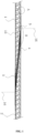
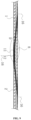
- FIGS. 1 to 4 illustrate a spanwise segment connection structure for wind turbine blades, comprising: a first segment 1 and a second segment 2 provided along the length direction of the wind turbine blade, wherein at least one splicing surface 3, in form of a slope structure, is provided between the first and second segments 1, 2; and a structural adhesive layer 4 provided at the splicing surface 3 for splicing and fixing the first and second segments 1, 2; wherein the bonding length of the structural adhesive layer 4 conforms to the inclination angle of the slope structure, and a biaxial fabric reinforcement layer 5 is provided on the outer side of a skin interface 16 of the splicing surface 3. It should be noted that 2 to 4 layers of the biaxial fabric reinforcement layer 5 are provided, with a total thickness exceeding 3 mm.
- the thickness of the structural adhesive layer 4 at the splicing surface 3 is comprised between 3 mm and 5 mm, and the inclination angle of the slope structure is preferably 6°.
- the weight of the blade is reduced and the production cost is reduced through the bonding and fixing of the first and second segments 1, 2.
- the splicing surface 3 in form of the slope structure provided at the segments of the wind turbine blade along the length direction (span direction) increases the bonding area, reduces the stress concentration on the splicing surface 3, and ensures bonding reliability of the first and second segments 1, 2.
- the biaxial reinforcing layer at the skin interface 16 of the splicing surface 3 ensures the uniformity of the force on the blade shell structure, thereby improving the stability of the overall structure of the blade.
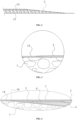
- an end of the biaxial fabric reinforcement layer 5 smoothly transitions to an outer skin 14 through a grinding process, which reduces stress concentration and influence on aerodynamic performance.
- the interface 16 of the outer skin 14 of the splicing surface 3 is provided with a slope recess 6 for laying a reinforcement layer 7 therein, and the strength of the interface 16 is improved through the reinforcement layer 7.
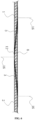
- Embodiment 1 The difference between this embodiment and Embodiment 1 is that two splicing surfaces 3 are adopted in the present embodiment, and the rest of the structure is the same, which will not be repeated here.
- two splicing surfaces 3 are provided between the first and second segments 1, 2.
- the two splicing faces 3 are symmetrically arranged and diffuse along the direction toward the outer skin 14.
- a connecting segment 8 is provided between the first and second segments 1, 2, and the connecting segment 8 is bonded and fixed on the splicing surfaces 3 of the first and second segments 1, 2.
- the connecting segment 8 is in form of a trapezoidal structure whose outer side is spliced with the outer skin 14 of the first and second segments 1, 2, and its inner side is spliced with an inner skin 15.
- the provision of the two splicing surfaces 3 facilitates the control of the accuracy of the connection between the first and second segments 1, 2 to reduce profile tolerances, ensuring the stability of the blade and improving the overall load bearing capacity of the blade.
- two splicing surfaces 3 are provided between the first and second segments 1, 2.
- the two splicing faces 3 are symmetrically arranged and diffuse along the direction toward the outer skin 14.
- a connecting segment 8 is provided between the first and second segments 1, 2, and the connecting segment 8 is bonded and fixed on the splicing surfaces 3 of the first and second segments 1, 2. Further, the connecting segment 8 is in form of a triangular structure whose outer surface is spliced with the outer skin 14 of the first and second segments 1, 2.
- connection section 8 in the form of triangular structure ensures the accuracy of the connection between the first and second segments 1, 2 and at the same time improves the stability at the interface 16.
- the tip of the triangular structure faces the inner skin 15 so that the inner skin 15 is bent and butt towards the outer skin 14, it results in a smaller thickness of the core material at the butt joint.
- the first and second segments 1, 2 adopt fiberglass butt joint 12 at the interface 16.
- Embodiments 2-3 lie in that a butting surface is added between the two splicing surfaces 3, and the rest of the structure is the same, which will not be repeated here.
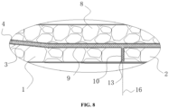
- a butting surface including a horizontal portion 9 and a vertical portion 10 is provided between the two splicing surfaces3, as shown in FIGS. 7-8 .
- the horizontal portion 9 is bonded and fixed to the connecting segment 8, and the vertical portion at the first segment 1 and the vertical portion at the second segment 2 abut each other and are bonded and fixed with a structural adhesive layer 4.
- the two symmetrical splicing surfaces 3 and the horizontal portion 9 form a recess into which the connecting segment 8 is overlapped.
- the connection between the first segment 1 and the second segment 2 is realized by butt joint of the vertical portion 10.
- the bonding area between the connecting segment 8 and the first and second segments 1, 2 is increased to ensure the strength of the connecting segment 8, thereby improving the overall load bearing capacity of the segmented blades.
- the core material at the butt joint of the vertical portion 10 has a certain thickness.
- the first segment 1 and the second segment 2 adopt the core material butt joint 13 at the interface 16.
- the difference between this embodiment and Embodiment 4 lies in the thickness of the core material at the butt joint and in the form of butt joint.
- the first and second segments 1, 2 extend horizontally near one end of the inner skin 15 and fit with the inner skin 15 to form a horizontal butting portion 11, and the horizontal butting portions of the first and second segments 1, 2 abut each other to form a horizontal portion 9 for fixing the connecting segment 8.
- the outer skin 14 of the first and second segments 1, 2 fits with the inner skin 15, and fiberglass butt joint 12 is adopted at the interface.
- the two symmetrical splicing surfaces 3 and the horizontal portion 9 form a recess into which the connecting segment 8 is overlapped to increase the bonding area between the connecting segment 8 and the first and second segments 1, 2, ensuring the strength of the connecting segment 8, thereby improving the overall load bearing capacity of the segmented blades.
Landscapes
- Engineering & Computer Science (AREA)
- Mechanical Engineering (AREA)
- Life Sciences & Earth Sciences (AREA)
- Sustainable Development (AREA)
- Sustainable Energy (AREA)
- Chemical & Material Sciences (AREA)
- Combustion & Propulsion (AREA)
- General Engineering & Computer Science (AREA)
- Wind Motors (AREA)
Applications Claiming Priority (2)
| Application Number | Priority Date | Filing Date | Title |
|---|---|---|---|
| CN202111328543 | 2021-11-10 | ||
| PCT/CN2022/114464 WO2023082767A1 (zh) | 2021-11-10 | 2022-08-24 | 一种风电叶片展向分块连接结构 |
Publications (4)
| Publication Number | Publication Date |
|---|---|
| EP4339451A1 true EP4339451A1 (de) | 2024-03-20 |
| EP4339451A4 EP4339451A4 (de) | 2024-10-23 |
| EP4339451C0 EP4339451C0 (de) | 2025-07-30 |
| EP4339451B1 EP4339451B1 (de) | 2025-07-30 |
Family
ID=80545505
Family Applications (1)
| Application Number | Title | Priority Date | Filing Date |
|---|---|---|---|
| EP22891574.0A Active EP4339451B1 (de) | 2021-11-10 | 2022-08-24 | Verbindungsstruktur für windturbinenrotorblattsegmente |
Country Status (4)
| Country | Link |
|---|---|
| US (1) | US20230407838A1 (de) |
| EP (1) | EP4339451B1 (de) |
| CN (1) | CN114183296B (de) |
| WO (1) | WO2023082767A1 (de) |
Families Citing this family (6)
| Publication number | Priority date | Publication date | Assignee | Title |
|---|---|---|---|---|
| CN114183296B (zh) * | 2021-11-10 | 2022-06-21 | 常州市宏发纵横新材料科技股份有限公司 | 一种风电叶片展向分块连接结构 |
| EP4191052A1 (de) * | 2021-12-01 | 2023-06-07 | Siemens Gamesa Renewable Energy A/S | Windturbinenschaufel und verfahren zur herstellung einer windturbinenschaufel |
| EP4338938B1 (de) | 2022-05-09 | 2025-07-30 | Newtech Group Co., Ltd. | Modulare klingenverbindungsstruktur, verfahren und werkzeug |
| CN114851581B (zh) * | 2022-05-09 | 2022-11-25 | 新创碳谷集团有限公司 | 一种模块化叶片连接结构、方法及工装 |
| CN116872510B (zh) * | 2023-09-08 | 2023-12-12 | 新创碳谷集团有限公司 | 一种模块化叶片分段处ud布的粘接定位工装及方法 |
| CN119244430B (zh) * | 2024-10-25 | 2025-06-24 | 中材科技风电叶片股份有限公司 | 风电叶片 |
Family Cites Families (21)
| Publication number | Priority date | Publication date | Assignee | Title |
|---|---|---|---|---|
| US7891947B2 (en) * | 2008-12-12 | 2011-02-22 | General Electric Company | Turbine blade and method of fabricating the same |
| US7998303B2 (en) * | 2009-05-28 | 2011-08-16 | General Electric Company | Method for assembling jointed wind turbine blade |
| GB201011539D0 (en) * | 2010-07-08 | 2010-08-25 | Blade Dynamics Ltd | A wind turbine blade |
| GB2488099A (en) * | 2011-01-31 | 2012-08-22 | Vestas Wind Sys As | Modular wind turbine blade with both spar and foil sections forming aerodynamic profile |
| IN2012DE00573A (de) * | 2012-02-29 | 2015-06-05 | Gen Electric | |
| CN202545134U (zh) * | 2012-04-16 | 2012-11-21 | 国电联合动力技术有限公司 | 一种分段式风轮叶片及其连接机构 |
| US20140169978A1 (en) * | 2012-12-19 | 2014-06-19 | General Electric Company | Rotor blade assemblies and methods for assembling the same |
| DK3019741T3 (en) * | 2013-07-09 | 2018-03-26 | Vestas Wind Sys As | WINDMILL LIVES WITH SECTIONS THAT ARE ASSEMBLED |
| US20150132141A1 (en) * | 2013-11-08 | 2015-05-14 | Siemens Aktiengesellschaft | Rotor blade of a wind turbine |
| GB201410429D0 (en) * | 2014-06-11 | 2014-07-23 | Lm Wp Patent Holding As | A tip system for a wild turbine blade |
| GB201509135D0 (en) * | 2015-05-28 | 2015-07-15 | Blade Dynamics Ltd | A wind turbine blade and a method of assembling a wind turbine blade and a spar cap connection piece. |
| GB201509155D0 (en) * | 2015-05-28 | 2015-07-15 | Blade Dynamics Ltd | A wind turbine blade and method of assembling a wind turbine blade |
| CN105526044A (zh) * | 2015-12-24 | 2016-04-27 | 东方电气风电有限公司 | 风力发电机分段组装叶片的连接结构及其制作方法 |
| CN108087191B (zh) * | 2017-12-25 | 2020-01-31 | 江苏金风科技有限公司 | 分段叶片、连接分段叶片的方法和风力发电机组 |
| DE102018103344A1 (de) * | 2018-02-14 | 2019-08-14 | Wobben Properties Gmbh | Verfahren zur Herstellung eines geteilten Rotorblatts und Rotorblatt |
| PL425656A1 (pl) * | 2018-05-21 | 2019-12-02 | Abt Accord Spolka Z Ograniczona Odpowiedzialnoscia | Łopatka turbiny |
| US11486352B2 (en) * | 2018-11-01 | 2022-11-01 | General Electric Company | Scarf connection for a wind turbine rotor blade |
| DK3751133T3 (da) * | 2019-06-14 | 2023-05-22 | Siemens Gamesa Renewable Energy As | Rotorvinge til en vindmølle |
| PT3804966T (pt) * | 2019-10-09 | 2023-08-09 | Siemens Gamesa Renewable Energy As | Método para fabrico de um elemento estrutural de uma pá de turbina eólica, método para fabrico de uma pá de turbina eólica, elemento estrutural de uma pá de turbina eólica e pá de turbina eólica |
| DK4050202T3 (da) * | 2021-02-24 | 2024-06-17 | Lm Wind Power As | En fremgangsmåde til samling af en vindmøllevinge |
| CN114183296B (zh) * | 2021-11-10 | 2022-06-21 | 常州市宏发纵横新材料科技股份有限公司 | 一种风电叶片展向分块连接结构 |
-
2021
- 2021-12-31 CN CN202111672107.7A patent/CN114183296B/zh active Active
-
2022
- 2022-08-24 WO PCT/CN2022/114464 patent/WO2023082767A1/zh not_active Ceased
- 2022-08-24 EP EP22891574.0A patent/EP4339451B1/de active Active
-
2023
- 2023-07-24 US US18/225,524 patent/US20230407838A1/en not_active Abandoned
Also Published As
| Publication number | Publication date |
|---|---|
| EP4339451A4 (de) | 2024-10-23 |
| WO2023082767A1 (zh) | 2023-05-19 |
| CN114183296B (zh) | 2022-06-21 |
| EP4339451C0 (de) | 2025-07-30 |
| CN114183296A (zh) | 2022-03-15 |
| EP4339451B1 (de) | 2025-07-30 |
| US20230407838A1 (en) | 2023-12-21 |
Similar Documents
| Publication | Publication Date | Title |
|---|---|---|
| EP4339451A1 (de) | Spannweise blockverbindungsstruktur für windturbinenschaufel | |
| US12060863B2 (en) | Chordwise segment connection structure for wind turbine blades | |
| US7841835B2 (en) | Spar cap for wind turbine blades | |
| CN113316684B (zh) | 风力涡轮机转子叶片的等电位结合 | |
| US20140271217A1 (en) | Efficient wind turbine blade design and associated manufacturing methods using rectangular spars and segmented shear web | |
| EP3027893B1 (de) | Windturbinenschaufel mit einem verbindungsstreifen angrenzend an einer sandwichplatte einer schaufel | |
| CN102278271B (zh) | 用于风力涡轮机转子叶片的后缘连结缘条 | |
| CN103291536A (zh) | 用于风力机转子叶片的叶片嵌件以及相关方法 | |
| CN210859042U (zh) | 一种主梁帽拼接结构及风机转子叶片 | |
| US12241448B2 (en) | Segmented wind turbine blade | |
| CN106499578A (zh) | 一种风电叶片叶尖延长结构及方法 | |
| CN113357075A (zh) | 一种风电叶片及风力发电机 | |
| CN115461538A (zh) | 叶片壳区段和包括叶片壳区段的风力涡轮机叶片 | |
| CN206352557U (zh) | 一种风电叶片叶尖延长结构 | |
| CN210106062U (zh) | 一种风轮叶片 | |
| US11486351B2 (en) | Sealing member for a sectioned wind turbine blade | |
| EP2505824A2 (de) | Verfahren zur Herstellung von Windturbinenschaufeln | |
| US20240301860A1 (en) | A wind turbine blade | |
| WO2023123712A1 (zh) | 叶片的腹板及叶片 | |
| CN223662004U (en) | Wind power blade and wind wheel | |
| US20250059945A1 (en) | Modular wind turbine blade | |
| US20250020099A1 (en) | Tip system for a wind turbine blade | |
| CN110905719A (zh) | 风电叶片及风力发电设备 | |
| WO2023072800A1 (en) | Segmented wind turbine blade | |
| WO2025214645A1 (en) | Method of manufacturing a wind turbine rotor blade, wind turbine rotor blade and transition piece |
Legal Events
| Date | Code | Title | Description |
|---|---|---|---|
| STAA | Information on the status of an ep patent application or granted ep patent |
Free format text: STATUS: THE INTERNATIONAL PUBLICATION HAS BEEN MADE |
|
| PUAI | Public reference made under article 153(3) epc to a published international application that has entered the european phase |
Free format text: ORIGINAL CODE: 0009012 |
|
| STAA | Information on the status of an ep patent application or granted ep patent |
Free format text: STATUS: REQUEST FOR EXAMINATION WAS MADE |
|
| 17P | Request for examination filed |
Effective date: 20231212 |
|
| AK | Designated contracting states |
Kind code of ref document: A1 Designated state(s): AL AT BE BG CH CY CZ DE DK EE ES FI FR GB GR HR HU IE IS IT LI LT LU LV MC MK MT NL NO PL PT RO RS SE SI SK SM TR |
|
| A4 | Supplementary search report drawn up and despatched |
Effective date: 20240924 |
|
| RIC1 | Information provided on ipc code assigned before grant |
Ipc: B29L 31/08 20060101ALI20240918BHEP Ipc: B29D 99/00 20100101ALI20240918BHEP Ipc: F03D 1/06 20060101AFI20240918BHEP |
|
| STAA | Information on the status of an ep patent application or granted ep patent |
Free format text: STATUS: EXAMINATION IS IN PROGRESS |
|
| 17Q | First examination report despatched |
Effective date: 20241220 |
|
| DAV | Request for validation of the european patent (deleted) | ||
| DAX | Request for extension of the european patent (deleted) | ||
| GRAP | Despatch of communication of intention to grant a patent |
Free format text: ORIGINAL CODE: EPIDOSNIGR1 |
|
| STAA | Information on the status of an ep patent application or granted ep patent |
Free format text: STATUS: GRANT OF PATENT IS INTENDED |
|
| INTG | Intention to grant announced |
Effective date: 20250429 |
|
| GRAS | Grant fee paid |
Free format text: ORIGINAL CODE: EPIDOSNIGR3 |
|
| GRAA | (expected) grant |
Free format text: ORIGINAL CODE: 0009210 |
|
| STAA | Information on the status of an ep patent application or granted ep patent |
Free format text: STATUS: THE PATENT HAS BEEN GRANTED |
|
| AK | Designated contracting states |
Kind code of ref document: B1 Designated state(s): AL AT BE BG CH CY CZ DE DK EE ES FI FR GB GR HR HU IE IS IT LI LT LU LV MC MK MT NL NO PL PT RO RS SE SI SK SM TR |
|
| REG | Reference to a national code |
Ref country code: GB Ref legal event code: FG4D |
|
| REG | Reference to a national code |
Ref country code: CH Ref legal event code: EP |
|
| REG | Reference to a national code |
Ref country code: DE Ref legal event code: R096 Ref document number: 602022018667 Country of ref document: DE |
|
| REG | Reference to a national code |
Ref country code: IE Ref legal event code: FG4D |
|
| U01 | Request for unitary effect filed |
Effective date: 20250731 |
|
| U07 | Unitary effect registered |
Designated state(s): AT BE BG DE DK EE FI FR IT LT LU LV MT NL PT RO SE SI Effective date: 20250811 |
|
| U20 | Renewal fee for the european patent with unitary effect paid |
Year of fee payment: 4 Effective date: 20250814 |