EP4339417A1 - Clamp assembly for clamping a drill string component - Google Patents
Clamp assembly for clamping a drill string component Download PDFInfo
- Publication number
- EP4339417A1 EP4339417A1 EP22195706.1A EP22195706A EP4339417A1 EP 4339417 A1 EP4339417 A1 EP 4339417A1 EP 22195706 A EP22195706 A EP 22195706A EP 4339417 A1 EP4339417 A1 EP 4339417A1
- Authority
- EP
- European Patent Office
- Prior art keywords
- clamping
- locking
- base body
- clamping jaw
- jaw base
- Prior art date
- Legal status (The legal status is an assumption and is not a legal conclusion. Google has not performed a legal analysis and makes no representation as to the accuracy of the status listed.)
- Pending
Links
- 238000005553 drilling Methods 0.000 claims description 7
- 238000006073 displacement reaction Methods 0.000 description 2
- 230000006978 adaptation Effects 0.000 description 1
- 230000001419 dependent effect Effects 0.000 description 1
Images


Classifications
-
- E—FIXED CONSTRUCTIONS
- E21—EARTH DRILLING; MINING
- E21B—EARTH DRILLING, e.g. DEEP DRILLING; OBTAINING OIL, GAS, WATER, SOLUBLE OR MELTABLE MATERIALS OR A SLURRY OF MINERALS FROM WELLS
- E21B19/00—Handling rods, casings, tubes or the like outside the borehole, e.g. in the derrick; Apparatus for feeding the rods or cables
- E21B19/10—Slips; Spiders ; Catching devices
-
- E—FIXED CONSTRUCTIONS
- E21—EARTH DRILLING; MINING
- E21B—EARTH DRILLING, e.g. DEEP DRILLING; OBTAINING OIL, GAS, WATER, SOLUBLE OR MELTABLE MATERIALS OR A SLURRY OF MINERALS FROM WELLS
- E21B19/00—Handling rods, casings, tubes or the like outside the borehole, e.g. in the derrick; Apparatus for feeding the rods or cables
- E21B19/16—Connecting or disconnecting pipe couplings or joints
-
- E—FIXED CONSTRUCTIONS
- E21—EARTH DRILLING; MINING
- E21B—EARTH DRILLING, e.g. DEEP DRILLING; OBTAINING OIL, GAS, WATER, SOLUBLE OR MELTABLE MATERIALS OR A SLURRY OF MINERALS FROM WELLS
- E21B19/00—Handling rods, casings, tubes or the like outside the borehole, e.g. in the derrick; Apparatus for feeding the rods or cables
- E21B19/02—Rod or cable suspensions
- E21B19/06—Elevators, i.e. rod- or tube-gripping devices
- E21B19/07—Slip-type elevators
-
- E—FIXED CONSTRUCTIONS
- E21—EARTH DRILLING; MINING
- E21B—EARTH DRILLING, e.g. DEEP DRILLING; OBTAINING OIL, GAS, WATER, SOLUBLE OR MELTABLE MATERIALS OR A SLURRY OF MINERALS FROM WELLS
- E21B31/00—Fishing for or freeing objects in boreholes or wells
- E21B31/12—Grappling tools, e.g. tongs or grabs
- E21B31/18—Grappling tools, e.g. tongs or grabs gripping externally, e.g. overshot
Definitions
- the invention relates to a clamping head arrangement for clamping a drill pipe element with a clamping head base, at least one clamping jaw base body, which is radially adjustable on the clamping head base between a clamping position and a release position relative to the drill pipe element, and at least one adapter element on the clamping jaw base body, the adapter element adapted to a shape of the drill pipe element to be tensioned and designed to rest against the drill pipe element in the clamping position and to tension it, according to the preamble of claim 1.
- a known clamping head arrangement is, for example, from EP 1 936 109 B1 out.
- a drill pipe element can be clamped and held with three clamping jaws offset from one another by 120°.
- Such clamping head arrangements are used in particular on drilling devices in which the drill pipe is composed of several drill pipe elements and is in particular screwed together.
- such clamping head arrangements can be used, for example, to hold the existing drill pipe so that it does not slip back into the drill pipe when it is withdrawn from the borehole.
- clamping jaws can transmit high torques via frictional force when clamped.
- a clamping head arrangement can also be movable axially or radially.
- the clamping head arrangement has clamping jaws with a contact surface with which the clamping jaw has the largest possible area of contact with the outer circumference of the drill pipe. This allows the highest possible adhesion and friction forces and thus the best possible holding force on the drill pipe.
- the invention is based on the object of specifying a clamping head arrangement with which adaptation to modified drill pipe elements can be carried out efficiently.
- the clamping head arrangement according to the invention is characterized in that the adapter element is detachably arranged on the clamping jaw base body and can be locked by means of an actuatable locking device and in that the locking device has at least one locking element which is locked and fixed between a locking position in which the adapter element is locked on the clamping jaw base body is, and is adjustable to a release position in which the adapter element is released and removable from the clamping jaw base body.
- a basic idea of the invention is that the adapter element, which represents the actual clamping jaw, is detachably mounted on a clamping jaw base body and locked by means of an actuable locking device.
- Complex connecting devices which in particular include screws, can be used omitted.
- an easy-to-use and preferably automatically or semi-automatically actuated locking device with a locking element is provided.
- the locking element can be adjusted between a locking position and a release position by a simple locking movement, in particular a linear or arcuate movement. With the locking device on the clamping jaw base body, quick release and locking and thus an efficient change of the adapter elements can be carried out.
- the clamping head base is essentially cylindrical or tubular.
- the clamping head base represents a base body or a frame on which the clamping jaw base bodies are mounted.
- the clamping head base can be ring-shaped or sleeve-shaped and encompass the drill pipe element on its outside.
- the clamping head base can also be designed in the form of a rod or in a similar manner, so that it can be arranged within a tubular linkage element.
- clamping can take place on the outside of the drill pipe element and/or on the inside of the drill pipe element.
- a single clamping jaw base body is arranged, which can be delivered to the drill pipe element with the clamping jaw or adapter element.
- several clamping jaw base bodies are arranged distributed over a circumference of the drill pipe element to be clamped.
- two, three or four or another suitable number of clamping jaw base bodies with corresponding adapter elements can be arranged in one plane distributed over the circumference of the drill pipe element.
- the adapter elements are arranged opposite one another in the radial direction, so that abutment forces can cancel each other out.
- At least one locking element is prestressed by a pretensioning device and held in the locking position.
- all locking elements of the clamping head arrangement are held prestressed in the locking position.
- the biasing device can in particular be a tension spring with which the locking element is held in the locking position with spring force.
- the at least one locking element has an actuating section for adjusting the locking element from the locking position to the release position.
- the actuating section can be a pin or a bolt, which preferably projects relative to the clamping jaw base body.
- At least one locking element is displaceably mounted on or in a clamping jaw base body and that an actuating section of the locking element protrudes in the locking position relative to the clamping jaw base body.
- the locking element can preferably be mounted adjustably on or in the clamping jaw base body in a corresponding receptacle.
- the actuating section of the locking element can preferably protrude out of the receptacle, so that the actuating section can be easily actuated.
- the at least one clamping jaw base body is mounted in an axially displaceable manner and that a wedge slide mechanism is formed on the clamping head base, through which an axial movement of the at least clamping jaw base body can be converted into a radial clamping movement.
- guide strips directed obliquely to the longitudinal axis of the drill pipe can be arranged on the clamping head base or the clamping head base can be conical as a whole, so that an axial displacement of the clamping jaw base body in the longitudinal direction also leads to a radial adjusting and clamping movement of the clamping jaw base body.
- At least one stop is arranged on the clamping head base, against which an actuating section of the locking element can be moved, the locking element being adjustable from its locking position into the release position.
- the actuating element can protrude forward in the direction of movement, so that the actuating element is pressed axially against a stop after a certain adjustment movement of the clamping jaw base body.
- the stop is arranged in such a way that the actuating section does not come into contact with the stop during a normal axial clamping movement for tensioning a drill pipe. Rather, this is only possible if no clamping of a drill pipe element is provided and accordingly no drill pipe is arranged in the clamping head arrangement.
- the locking element can be adjusted from the locking position into the release position via the actuating element.
- the unlocked adapter element can then be removed from the clamping jaw base body and a new, adapted adapter element can be inserted.
- This version can be used to unlock or lock the actuator, which is also intended to carry out the clamping movement during a drilling operation.
- a preferred embodiment of the invention consists in particular in that an adjusting device, in particular with at least one adjusting cylinder, is arranged, with which the at least one clamping jaw base body can be adjusted.
- the adjusting device can in particular have one or more hydraulic cylinders, which are preferably aligned parallel to the longitudinal axis of the drill pipe element to be tensioned.
- a further expedient embodiment variant of the invention is that the adapter element has at least one holding section which projects into a recess in the clamping jaw base body, and that the at least one holding section is designed with the at least one locking element of the clamping jaw base body for at least positive fixing of the adapter element on the clamping jaw base body.
- the fixing can preferably take place not only in a form-fitting manner, but also in a force-fitting manner.
- the holding section has a holding pin on which a locking recess is formed, in which the locking element engages with a locking section for positive locking in the locking position.
- a through hole or preferably an outer recess, in particular also an annular recess can be arranged on the holding section, into which the locking element engages in a form-fitting manner with at least one locking section. This ensures that the adapter element is held reliably on the clamping jaw base body.
- the locking element has a release section, which is arranged on the locking recess in the release position in such a way that the adapter element with the holding section can be removed from the clamping jaw base body.
- the locking element can in particular be a pin- or bolt-shaped locking element, in which the release section is formed by a recess. If this recess of the release section is moved into the area of the locking recess of the holding section of the adapter element, the positive locking can be canceled. In this release position, the adapter element with the holding section can be released and removed from the clamping jaw base body.
- the invention further comprises a drilling device for creating a borehole, in particular in a ground, with at least one drill pipe element, the previously described clamping head arrangement according to the invention being provided.
- a drilling device for creating a borehole, in particular in a ground, with at least one drill pipe element, the previously described clamping head arrangement according to the invention being provided.
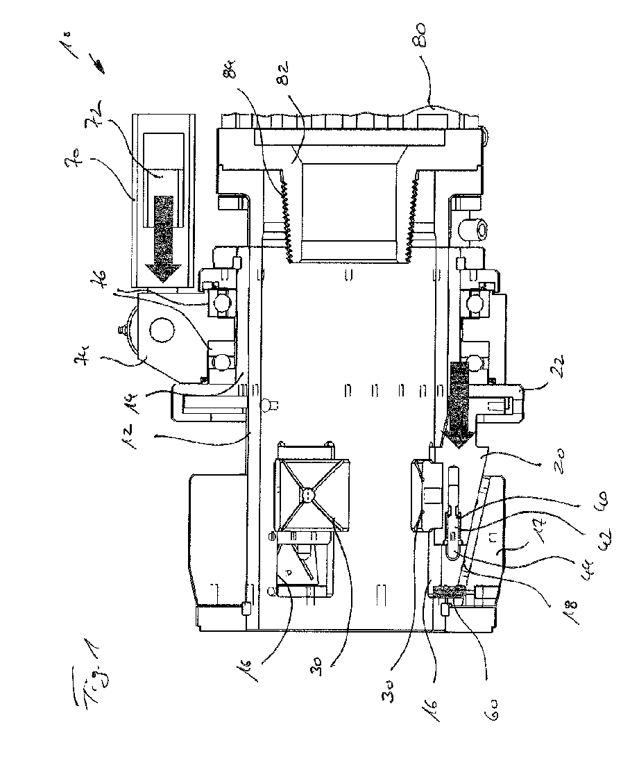
- a clamping head arrangement 10 according to the invention with a sleeve-shaped clamping head base 12 is shown schematically in Figure 1 shown.
- the clamping head arrangement 10 can be firmly attached to a partially indicated rotary drive 80 and in particular to a rotationally driven output element 82 with a connector with an external thread 84.
- the clamping head base 12 can thus rotate with the output element 82 of the rotary drive 80.
- a drill pipe with a corresponding internal thread can be screwed on via the external thread 84 of the output element 82.
- the drill pipe is arranged within the sleeve-shaped clamping head base 12 and in Figure 1 not shown.
- a clamping head slide 14 is mounted in an axially displaceable manner.
- an adjusting device 70 with one or more adjusting cylinders 72 can be arranged, as also shown schematically in Figure 1 is shown.
- the adjusting device 70 can be firmly attached to a base body (not shown), such as a drilling device, and can be stationary relative to the rotating drive element 82.
- an actuator 74 can be moved, which is connected to the axially movable clamping slide 14 via pivot bearings 76. In this way, an axial adjusting movement can be transmitted from the relatively fixed adjusting device 70 to the clamping slide 14 on the clamping head base 12, which rotates about a longitudinal and/or rotational axis.
- one or more clamping jaw base bodies 20 can be connected to the clamping slide 14 by means of an annular holder 22.
- the holder 22 can be designed in such a way that it creates an axially fixed connection with the at least one clamping jaw base body 20, but allows a radial movement of the clamping jaw base body 20 with respect to the clamping head base 12 with respect to the longitudinal or rotation axis.
- An outer side surface of the clamping jaw base body 20 is inclined or conical, so that it forms a wedge slide mechanism 18 with a corresponding inclined or conical guide element 17, which is firmly attached to the outside of the clamping head base 12.
- the wedge slide mechanism 18 is designed in such a way that during an axial feed movement of the clamping slide 14, the clamping jaw base body 20 is adjusted not only axially but also in a defined manner in a radial direction, in particular radially inwards.
- plate-like adapter elements 30 are arranged on the radial inside, preferably arcuate on the inside and adapted to the drill pipe element to be clamped.
- the adapter elements 30 extend through window-like passages 16 in the clamping head base 12 from the clamping jaw base body 20 attached to the radial outside into the interior of the sleeve-shaped clamping head base 12. Due to the radial movement of the clamping jaw base body 20 with the adapter elements 30 attached thereto, a Radial non-positive clamping of a cylindrical drill pipe element arranged in the clamping head base 12 takes place.
- the clamping jaw base body 20 with the adapter element 30 is reset radially again, the tension of a drill pipe element being released.
- the adapter elements 30 are each held releasably and interchangeably on the clamping jaw base body 20 by means of a locking device 40, the locking device 40 having a bolt-like locking element 42 arranged parallel to the longitudinal or rotation axis with a pin-like actuating section 44, which is opposite an end face of the associated clamping jaw base body 20 projects axially.
- the clamping jaw base body 20 can be moved to a front end position, in which the actuating section 44 of the locking element 42 is pressed against an axial stop 60.
- the functionality of the locking device 40 is described in more detail below in connection with the other figures.
- FIG 2 a clamping jaw base body 20 is shown in an enlarged view.
- the clamping jaw base body 20 has a recess 26 into which the adapter element 30 with a holding section 36 is fitted.
- the adapter element 30 has an arcuate clamping surface 32 on its top, the contour of which is adapted to an outer contour of a cylindrical drill pipe element to be clamped.
- the locking device 40 with a bolt-shaped locking element 42 is arranged within the clamping jaw base body 20.
- the locking element 42 is slidably mounted and held in a receiving hole in the clamping jaw base body 20 via a screwed fastening plate 24, with a pin-shaped actuating section 44 with a dome-shaped head protruding from the clamping jaw base body 20 in a defined manner from the locking element 42.
- FIG. 3 This shows Figure 3 the locking device 40 in its locking position.
- the bolt-shaped locking element 42 is held in the locking position via a pretensioning device 50, which according to the illustrated embodiment can be designed as a helical spring 52.
- a locking section 46 of the locking element 42 engages in an annular groove-shaped locking recess 38 of a holding pin 37, which is formed on an underside of the holding section 36 of the adapter element 30.
- the holding pin 37 is accommodated in a corresponding receiving hole within the clamping jaw base body 20.
- the retaining pin 37 is in the Locking recess 38 engaging locking section 46 held in a form-fitting manner.
- the front actuation section 44 of the locking element 42 projects axially in a defined manner relative to the fastening plate 24 attached to the clamping jaw base body 20.
- the clamping jaw base body 20 will now be in accordance with the Figure 1 Moved axially against the stop 60, the actuating section 44 and thus the locking element 42 are pressed inwards into a release position, which is shown schematically in Figure 4 is shown.
- the larger diameter locking section 46 disengages from the locking recess 38.
- a release section 48 of the locking element 42 is pushed.
- the release section 48 has a smaller diameter than the adjacent locking section 46.
- the release section 48 is designed in such a way that the retaining pin 37 is no longer positively blocked and the adapter element 30 can therefore be pulled upwards out of the recess 26 on the clamping jaw base body 20. like in Figure 5 is shown.
- a new adapter element 30 can then be inserted into the clamping jaw base body 20, which preferably has a different arcuate contour of the clamping surface 32.
- the clamping jaw base body 20 can be adjusted accordingly Figure 1 can be pushed away from the stop 60 again with the adjusting device 70.
- the bolt-shaped locking element 42 is adjusted.
- the locking element 42 is returned to the locking position by the pretensioning device 50 with the coil spring 52, which is compressed in the release position.
- the locking element 42 takes the position again accordingly Figure 3 a.
Abstract
Die Erfindung betrifft eine Spannkopfanordnung zum Spannen eines Bohrgestängeelementes mit einer Spannkopfbasis, mindestens einem Spannbacken-Grundkörper, welcher an der Spannkopfbasis zwischen einer Spannposition und einer Löseposition relativ zu dem Bohrgestängeelement radial verstellbar ist, und mindestens einem Adapterelement an dem Spannbacken-Grundkörper, wobei das Adapterelement an eine Form des zu spannenden Bohrgestängeelementes angepasst und ausgebildet ist, in der Spannposition an dem Bohrgestängeelement anzuliegen und zu spannen. Nach der Erfindung ist vorgesehen, dass das Adapterelement lösbar an dem Spannbacken-Grundkörper angeordnet und mittels einer betätigbaren Verriegelungseinrichtung verriegelbar ist und dass die Verriegelungseinrichtung mindestens ein Riegelelement aufweist, welches zwischen einer Verriegelungsposition, in welcher das Adapterelement an dem Spannbacken-Grundkörper verriegelt und festgelegt ist, und einer Freigabeposition verstellbar ist, in welcher das Adapterelement gelöst und von dem Spannbacken-Grundkörper entnehmbar ist.

Description
Die Erfindung betrifft eine Spannkopfanordnung zum Spannen eines Bohrgestängeelementes mit einer Spannkopfbasis, mindestens einem Spannbacken-Grundkörper, welcher an der Spannkopfbasis zwischen einer Spannposition und einer Löseposition relativ zu dem Bohrgestängeelement radial verstellbar ist, und mindestens einem Adapterelement an dem Spannbacken-Grundkörper, wobei das Adapterelement an eine Form des zu spannenden Bohrgestängeelementes angepasst und ausgebildet ist, in der Spannposition an dem Bohrgestängeelement anzuliegen und dieses zu spannen, gemäß dem Oberbegriff des Anspruchs 1.The invention relates to a clamping head arrangement for clamping a drill pipe element with a clamping head base, at least one clamping jaw base body, which is radially adjustable on the clamping head base between a clamping position and a release position relative to the drill pipe element, and at least one adapter element on the clamping jaw base body, the adapter element adapted to a shape of the drill pipe element to be tensioned and designed to rest against the drill pipe element in the clamping position and to tension it, according to the preamble of claim 1.
Eine bekannte Spannkopfanordnung geht beispielsweise aus der
Die Spannkopfanordnung weist Spannbacken mit einer Kontaktfläche auf, mit welcher die Spannbacke einen möglichst großflächigen Kontakt mit dem Außenumfang des Bohrgestänges hat. Dies erlaubt möglichst hohe Haft- und Reibungskräfte und damit eine möglichst gute Haltekraft an dem Bohrgestänge.The clamping head arrangement has clamping jaws with a contact surface with which the clamping jaw has the largest possible area of contact with the outer circumference of the drill pipe. This allows the highest possible adhesion and friction forces and thus the best possible holding force on the drill pipe.
Bei einer Änderung des Durchmessers des Bohrgestänges ist es daher üblich, die eigentlichen Spannbacken, welche auch als Adapterelemente bezeichnet werden können, auszuwechseln und durch andere Spannbacken zu ersetzen, deren Kontur an den geänderten Außenumfang des Bohrgestänges angepasst ist.When changing the diameter of the drill pipe, it is therefore common to replace the actual clamping jaws, which can also be referred to as adapter elements, and replace them with other clamping jaws whose contour is adapted to the changed outer circumference of the drill pipe.
Hierzu ist es bekannt, Verbindungseinrichtungen an den Spannbacken zu lösen, die bestehenden Spannbacken zu entfernen und durch neue Spannbacken zu ersetzen. Anschließend sind die Verbindungseinrichtungen wieder zu schließen, so dass dann die Spannkopfanordnung wieder einsatzbereit ist. Diese Wechselarbeiten sind manuell auszuführen und sind mit einem nicht unerheblichen Zeit- und Arbeitsaufwand verbunden.For this purpose, it is known to loosen connecting devices on the clamping jaws, remove the existing clamping jaws and replace them with new clamping jaws. The connecting devices must then be closed again so that the clamping head arrangement is ready for use again. These changing tasks have to be carried out manually and involve a considerable amount of time and effort.
Der Erfindung liegt die Aufgabe zugrunde, eine Spannkopfanordnung anzugeben, mit welcher eine Anpassung an geänderte Bohrgestängeelemente effizient erfolgen kann.The invention is based on the object of specifying a clamping head arrangement with which adaptation to modified drill pipe elements can be carried out efficiently.
Die Aufgabe wird nach der Erfindung durch eine Spannkopfanordnung mit den Merkmalen des Anspruchs 1 gelöst. Bevorzugte Ausführungsformen der Erfindung sind in den abhängigen Ansprüchen angegeben.The object is achieved according to the invention by a clamping head arrangement with the features of claim 1. Preferred embodiments of the invention are set out in the dependent claims.
Die erfindungsgemäße Spannkopfanordnung ist dadurch gekennzeichnet, dass das Adapterelement lösbar an dem Spannbacken-Grundkörper angeordnet und mittels einer betätigbaren Verriegelungseinrichtung verriegelbar ist und dass die Verriegelungseinrichtung mindestens ein Riegelelement aufweist, welches zwischen einer Verriegelungsposition, in welcher das Adapterelement an dem Spannbacken-Grundkörper verriegelt und festgelegt ist, und einer Freigabeposition verstellbar ist, in welcher das Adapterelement gelöst und von dem Spannbacken-Grundkörper entnehmbar ist.The clamping head arrangement according to the invention is characterized in that the adapter element is detachably arranged on the clamping jaw base body and can be locked by means of an actuatable locking device and in that the locking device has at least one locking element which is locked and fixed between a locking position in which the adapter element is locked on the clamping jaw base body is, and is adjustable to a release position in which the adapter element is released and removable from the clamping jaw base body.
Eine Grundidee der Erfindung liegt darin, dass Adapterelement, welches die eigentliche Spannbacke darstellt, lösbar an einem Spannbacken-Grundkörper zu lagern und mittels einer betätigbaren Verriegelungseinrichtung zu verriegeln. Aufwendige Verbindungseinrichtungen, welche insbesondere Schrauben umfassen, können dabei entfallen. Vielmehr ist eine einfach zu bedienende und vorzugsweise automatisch oder teilautomatisch betätigbare Verriegelungseinrichtung mit einem Riegelelement vorgesehen. Das Riegelelement ist durch eine einfache Riegelbewegung, insbesondere eine lineare oder bogenförmige Bewegung, zwischen einer Verriegelungsposition und einer Freigabeposition verstellbar. Mit der Verriegelungseinrichtung an dem Spannbacken-Grundkörper kann so ein schnelles Lösen und Verriegeln und damit ein effizienter Wechsel der Adapterelemente vorgenommen werden.A basic idea of the invention is that the adapter element, which represents the actual clamping jaw, is detachably mounted on a clamping jaw base body and locked by means of an actuable locking device. Complex connecting devices, which in particular include screws, can be used omitted. Rather, an easy-to-use and preferably automatically or semi-automatically actuated locking device with a locking element is provided. The locking element can be adjusted between a locking position and a release position by a simple locking movement, in particular a linear or arcuate movement. With the locking device on the clamping jaw base body, quick release and locking and thus an efficient change of the adapter elements can be carried out.
Eine bevorzugte Ausführungsform der Erfindung besteht darin, dass die Spannkopfbasis im Wesentlich zylindrisch oder rohrförmig ausgebildet ist. Die Spannkopfbasis stellt einen Grundkörper oder einen Rahmen dar, an welchem die Spannbacken-Grundkörper gelagert sind. Die Spannkopfbasis kann ringförmig oder hülsenförmig ausgebildet sein und das Bohrgestängeelement an seiner Außenseite umfassen. Alternativ oder ergänzend kann die Spannkopfbasis auch stangenförmig oder in ähnlicher Weise ausgebildet sein, so dass diese innerhalb eines rohrförmigen Gestängeelementes angeordnet werden kann. Abhängig von der Gestaltung der Spannkopfbasis kann so ein Spannen an der Außenseite des Bohrgestängeelementes und/oder an der Innenseite des Bohrgestängeelementes erfolgen.A preferred embodiment of the invention is that the clamping head base is essentially cylindrical or tubular. The clamping head base represents a base body or a frame on which the clamping jaw base bodies are mounted. The clamping head base can be ring-shaped or sleeve-shaped and encompass the drill pipe element on its outside. Alternatively or additionally, the clamping head base can also be designed in the form of a rod or in a similar manner, so that it can be arranged within a tubular linkage element. Depending on the design of the clamping head base, clamping can take place on the outside of the drill pipe element and/or on the inside of the drill pipe element.
In einer einfachen Ausführung kann es ausreichend sein, dass ein einzelner Spannbacken-Grundkörper angeordnet ist, welcher auf das Bohrgestängeelement mit dem Spannbacken oder Adapterelement zugestellt werden kann. Besonders vorteilhaft ist es nach einer Weiterbildung der Erfindung, dass mehrere Spannbacken-Grundkörper über einen Umfang des zu spannenden Bohrgestängeelementes verteilt angeordnet sind. Insbesondere können zwei, drei oder vier oder eine sonstige geeignete Anzahl von Spannbacken-Grundkörpern mit entsprechenden Adapterelementen über den Umfang des Bohrgestängeelementes verteilt in einer Ebene angeordnet sein. Insbesondere sind dabei die Adapterelemente in radialer Richtung gegenüberliegend zueinander angeordnet, so dass sich Widerlagerkräfte gegeneinander aufheben können.In a simple embodiment, it may be sufficient that a single clamping jaw base body is arranged, which can be delivered to the drill pipe element with the clamping jaw or adapter element. According to a further development of the invention, it is particularly advantageous that several clamping jaw base bodies are arranged distributed over a circumference of the drill pipe element to be clamped. In particular, two, three or four or another suitable number of clamping jaw base bodies with corresponding adapter elements can be arranged in one plane distributed over the circumference of the drill pipe element. In particular, the adapter elements are arranged opposite one another in the radial direction, so that abutment forces can cancel each other out.
Nach einer weiteren Ausführung der Erfindung ist es vorteilhaft, dass mindestens ein Riegelelement durch eine Vorspanneinrichtung vorgespannt und in der Verriegelungsposition gehalten ist. Vorzugsweise sind alle Riegelelemente der Spannkopfanordnung in der Verriegelungsposition vorgespannt gehalten. Dies sichert einen Fail-Safe-Betrieb. Die Vorspanneinrichtung kann dabei insbesondere eine Spannfeder sein, mit welcher das Riegelelement in der Verriegelungsposition mit Federkraft gehalten wird. Somit muss zum Lösen des Adapterelementes das Verriegelungselement mit Kraft gegen die Vorspanneinrichtung aktiv in die Löseposition bewegt werden. Nach Entfall der Kraft nimmt das Riegelelement wieder die Verriegelungsposition ein.According to a further embodiment of the invention, it is advantageous that at least one locking element is prestressed by a pretensioning device and held in the locking position. Preferably, all locking elements of the clamping head arrangement are held prestressed in the locking position. This ensures fail-safe operation. The biasing device can in particular be a tension spring with which the locking element is held in the locking position with spring force. Thus, in order to release the adapter element, the locking element must be actively moved into the release position with force against the pretensioning device. After the force is removed, the locking element returns to the locking position.
Weiter ist es bevorzugt, dass das mindestens eine Riegelelement einen Betätigungsabschnitt zum Verstellen des Riegelelementes aus der Verriegelungsposition in die Freigabeposition aufweist. Insbesondere kann der Betätigungsabschnitt ein Zapfen oder ein Bolzen sein, welcher vorzugsweise gegenüber dem Spannbacken-Grundkörper vorsteht. Durch Betätigen des Betätigungsabschnitts, insbesondere durch Aufbringen einer Druckkraft auf den Betätigungsabschnitt, kann das Riegelelement aus der Verriegelungsposition in die Freigabeposition verstellt werden.It is further preferred that the at least one locking element has an actuating section for adjusting the locking element from the locking position to the release position. In particular, the actuating section can be a pin or a bolt, which preferably projects relative to the clamping jaw base body. By actuating the actuating section, in particular by applying a pressure force to the actuating section, the locking element can be adjusted from the locking position to the release position.
Insbesondere ist es nach einer Ausführungsform der Erfindung vorteilhaft, dass mindestens ein Riegelelement verschiebbar an oder in einem Spannbacken-Grundkörper gelagert ist und dass ein Betätigungsabschnitt des Riegelelementes in der Verriegelungsposition gegenüber dem Spannbacken-Grundkörper vorsteht. Das Riegelelement kann vorzugsweise an oder in dem Spannbacken-Grundkörper in einer entsprechenden Aufnahme verstellbar gelagert sein. Der Betätigungsabschnitt des Riegelelementes kann dabei vorzugsweise aus der Aufnahme heraus vorragen, so dass der Betätigungsabschnitt einfach betätigt werden kann.In particular, according to one embodiment of the invention, it is advantageous that at least one locking element is displaceably mounted on or in a clamping jaw base body and that an actuating section of the locking element protrudes in the locking position relative to the clamping jaw base body. The locking element can preferably be mounted adjustably on or in the clamping jaw base body in a corresponding receptacle. The actuating section of the locking element can preferably protrude out of the receptacle, so that the actuating section can be easily actuated.
Nach einer weiteren Ausführungsform der Erfindung ist es bevorzugt, dass der mindestens eine Spannbacken-Grundkörper axial verschiebbar gelagert ist und dass an der Spannkopfbasis ein Keilschiebermechanismus ausgebildet ist, durch welchen eine Axialbewegung des mindestens Spannbacken-Grundkörpers in eine radiale Spannbewegung umsetzbar ist. An der Spannkopfbasis können insbesondere schräg zur Längsachse des Bohrgestänges gerichtete Führungsleisten angeordnet oder die Spannkopfbasis insgesamt konisch ausgebildet sein, so dass eine Axialverschiebung des Spannbacken-Grundkörpers in Längsrichtung auch zu einer radialen Stell- und Spannbewegung des Spannbacken-Grundkörpers führt.According to a further embodiment of the invention, it is preferred that the at least one clamping jaw base body is mounted in an axially displaceable manner and that a wedge slide mechanism is formed on the clamping head base, through which an axial movement of the at least clamping jaw base body can be converted into a radial clamping movement. In particular, guide strips directed obliquely to the longitudinal axis of the drill pipe can be arranged on the clamping head base or the clamping head base can be conical as a whole, so that an axial displacement of the clamping jaw base body in the longitudinal direction also leads to a radial adjusting and clamping movement of the clamping jaw base body.
Nach einer Weiterbildung ist es dabei insbesondere vorteilhaft, dass an der Spannkopfbasis mindestens ein Anschlag angeordnet ist, gegen welchen ein Betätigungsabschnitt des Riegelelementes bewegbar ist, wobei das Riegelelement aus seiner Verriegelungsposition in die Freigabeposition verstellbar ist. Insbesondere kann bei einer Axialbewegung das Betätigungselement in Bewegungsrichtung nach vorne vorragen, so dass das Betätigungselement nach einer gewissen Verstellbewegung des Spannbacken-Grundkörpers axial gegen einen Anschlag gedrückt wird. Der Anschlag ist dabei derart angeordnet, dass der Betätigungsabschnitt bei einer normalen axialen Spannbewegung zum Spannen eines Bohrgestänges nicht in Kontakt mit dem Anschlag gelangt. Vielmehr ist dies nur möglich, wenn kein Spannen eines Bohrgestängeelementes vorgesehen ist und entsprechend kein Bohrgestänge in der Spannkopfanordnung angeordnet ist. Durch den Anschlag kann so über das Betätigungselement das Riegelelement aus der Verriegelungsposition in die Freigabeposition verstellt werden. In dieser kann dann das entriegelte Adapterelement von dem Spannbacken-Grundkörper entnommen und ein neues angepasstes Adapterelement eingesetzt werden. Über diese Ausführung kann zum Entriegeln beziehungsweise Verriegeln der Stellantrieb verwendet werden, welcher bei einem Bohrbetrieb auch zum Ausführen der Spannbewegung vorgesehen ist.According to a further development, it is particularly advantageous that at least one stop is arranged on the clamping head base, against which an actuating section of the locking element can be moved, the locking element being adjustable from its locking position into the release position. In particular, during an axial movement, the actuating element can protrude forward in the direction of movement, so that the actuating element is pressed axially against a stop after a certain adjustment movement of the clamping jaw base body. The stop is arranged in such a way that the actuating section does not come into contact with the stop during a normal axial clamping movement for tensioning a drill pipe. Rather, this is only possible if no clamping of a drill pipe element is provided and accordingly no drill pipe is arranged in the clamping head arrangement. Through the stop, the locking element can be adjusted from the locking position into the release position via the actuating element. The unlocked adapter element can then be removed from the clamping jaw base body and a new, adapted adapter element can be inserted. This version can be used to unlock or lock the actuator, which is also intended to carry out the clamping movement during a drilling operation.
Dabei besteht eine bevorzugte Ausführungsform der Erfindung insbesondere darin, dass eine Stelleinrichtung, insbesondere mit mindestens einem Stellzylinder, angeordnet ist, mit welcher der mindestens eine Spannbacken-Grundkörper verstellbar ist. Die Stelleinrichtung kann insbesondere einen oder mehrere Hydraulikzylinder aufweisen, welche vorzugsweise parallel zur Längsachse des zu spannenden Bohrgestängeelementes ausgerichtet ist.A preferred embodiment of the invention consists in particular in that an adjusting device, in particular with at least one adjusting cylinder, is arranged, with which the at least one clamping jaw base body can be adjusted. The adjusting device can in particular have one or more hydraulic cylinders, which are preferably aligned parallel to the longitudinal axis of the drill pipe element to be tensioned.
Eine weitere zweckmäßige Ausführungsvariante der Erfindung besteht darin, dass das Adapterelement mindestens einen Halteabschnitt aufweist, welcher in eine Ausnehmung in dem Spannbacken-Grundkörper hineinragt, und dass der mindestens eine Halteabschnitt ausgebildet ist, mit dem mindestens einem Riegelelement des Spannbacken-Grundkörpers zum mindestens formschlüssigen Festlegen des Adapterelementes an dem Spannbacken-Grundkörper zusammenzuwirken. Das Festlegen kann vorzugsweise nicht nur formschlüssig, sondern auch kraftschlüssig erfolgen.A further expedient embodiment variant of the invention is that the adapter element has at least one holding section which projects into a recess in the clamping jaw base body, and that the at least one holding section is designed with the at least one locking element of the clamping jaw base body for at least positive fixing of the adapter element on the clamping jaw base body. The fixing can preferably take place not only in a form-fitting manner, but also in a force-fitting manner.
Insbesondere ist es dabei vorteilhaft, dass der Halteabschnitt einen Haltezapfen aufweist, an welchem eine Verriegelungsausnehmung ausgebildet ist, in welcher das Riegelelement mit einem Riegelabschnitt zum formschlüssigen Verriegeln in die Riegelposition eingreift. An dem Halteabschnitt kann insbesondere ein Durchgangsloch oder vorzugsweise eine äußere Ausnehmung, insbesondere auch eine ringförmige Ausnehmung angeordnet sein, in welche das Riegelelement mit mindestens einem Riegelabschnitt formschlüssig eingreift. Dies sichert ein zuverlässiges Halten des Adapterelementes an dem Spannbacken-Grundkörper.In particular, it is advantageous that the holding section has a holding pin on which a locking recess is formed, in which the locking element engages with a locking section for positive locking in the locking position. In particular, a through hole or preferably an outer recess, in particular also an annular recess, can be arranged on the holding section, into which the locking element engages in a form-fitting manner with at least one locking section. This ensures that the adapter element is held reliably on the clamping jaw base body.
Weiterhin kann es nach einer Ausführungsvariante der Erfindung dabei vorgesehen sein, dass das Riegelelement einen Freigabeabschnitt aufweist, welcher in der Freigabeposition derart an der Verriegelungsausnehmung angeordnet ist, dass das Adapterelement mit dem Halteabschnitt aus dem Spannbacken-Grundkörper entnehmbar ist. Das Riegelelement kann insbesondere ein stift- oder bolzenförmiges Riegelelement sein, bei welchem der Freigabeabschnitt durch eine Ausnehmung gebildet ist. Wird diese Ausnehmung des Freigabeabschnitts in den Bereich der Verriegelungsausnehmung des Halteabschnitts des Adapterelementes bewegt, kann so die formschlüssige Verriegelung aufgehoben werden. In dieser Freigabeposition kann das Adapterelement mit dem Halteabschnitt von dem Spannbacken-Grundkörper gelöst und entfernt werden.Furthermore, according to an embodiment variant of the invention, it can be provided that the locking element has a release section, which is arranged on the locking recess in the release position in such a way that the adapter element with the holding section can be removed from the clamping jaw base body. The locking element can in particular be a pin- or bolt-shaped locking element, in which the release section is formed by a recess. If this recess of the release section is moved into the area of the locking recess of the holding section of the adapter element, the positive locking can be canceled. In this release position, the adapter element with the holding section can be released and removed from the clamping jaw base body.
Die Erfindung umfasst weiter ein Bohrgerät zum Erstellen einer Bohrung, insbesondere in einem Boden, mit mindestens einem Bohrgestängeelement, wobei die zuvor beschriebene erfindungsgemäße Spannkopfanordnung gegeben ist. Mit einem derartigen Bohrgerät können die zuvor beschriebenen Vorteile erzielt werden, insbesondere wenn ein Wechsel des Bohrgestänges mit einem anderen Außendurchmesser ansteht.The invention further comprises a drilling device for creating a borehole, in particular in a ground, with at least one drill pipe element, the previously described clamping head arrangement according to the invention being provided. With such a drilling device, the advantages described above can be achieved, especially if the drill pipe with a different outer diameter needs to be changed.
Die Erfindung wird nachfolgend anhand von bevorzugten Ausführungsbeispielen weiter beschrieben, welche schematisch in den Zeichnungen dargestellt sind. In den Zeichnungen zeigen:
- Fig. 1
- eine Querschnittsansicht durch eine erfindungsgemäße Spannkopfanordnung;
- Fig. 2
- eine perspektivische Ansicht zu einem Spannbacken-Grundkörper mit eingesetzten Adapterelement in Verriegelungsposition;
- Fig. 3
- eine perspektivische Ansicht des Adapterelementes mit dem zughörigen Riegelelement in der Verriegelungsposition ohne den Spannbacken-Grundkörper;
- Fig. 4
- eine perspektivische Ansicht von Adapterelement und Riegelelement entsprechend
Figur 3 , jedoch in einer Freigabeposition des Riegelelementes; und - Fig. 5
- eine perspektivische Ansicht des Spannbacken-Grundkörpers entsprechend
Figur 2 bei Entnehmen des Adapterelementes in der Freigabeposition.
- Fig. 1
- a cross-sectional view through a clamping head arrangement according to the invention;
- Fig. 2
- a perspective view of a clamping jaw base body with an inserted adapter element in the locking position;
- Fig. 3
- a perspective view of the adapter element with the associated locking element in the locking position without the clamping jaw base body;
- Fig. 4
- a perspective view of the adapter element and locking element accordingly
Figure 3 , but in a release position of the locking element; and - Fig. 5
- a perspective view of the clamping jaw base body accordingly
Figure 2 when removing the adapter element in the release position.
Eine erfindungsgemäße Spannkopfanordnung 10 mit einer hülsenförmigen Spannkopfbasis 12 ist schematisch in
An der Außenseite der hülsenförmigen Spannkopfbasis 12 ist ein Spannkopfschlitten 14 axial verschiebbar gelagert. Zum axialen Verschieben kann eine Stelleinrichtung 70 mit einem oder mehreren Stellzylindern 72 angeordnet sein, wie schematisch ebenfalls in
An einer Vorderseite des Spannschlittens 14 können ein oder mehrere Spannbacken-Grundkörper 20 mittels einer ringförmigen Halterung 22 mit dem Spannschlitten 14 verbunden sein. Die Halterung 22 kann dabei so ausgebildet sein, dass diese eine axial feste Verbindung mit dem mindestens einen Spannbacken-Grundkörper 20 schafft, jedoch eine in Bezug auf die Längs- oder Drehachse radial Bewegung des Spannbacken-Grundkörpers 20 in Bezug auf die Spannkopfbasis 12 zulässt.On a front side of the clamping
Eine Außenseitenfläche des Spannbacken-Grundkörpers 20 ist geneigt oder konisch ausgebildet, so dass diese mit einem korrespondierenden geneigten oder konischen Führungselement 17, welches fest an der Außenseite der Spannkopfbasis 12 angebracht ist, einen Keilschiebermechanismus 18 bildet. Der Keilschiebermechanismus 18 ist derart ausgebildet, dass bei einer axialen Vorschubbewegung des Spannschlittens 14 der Spannbacken-Grundkörper 20 nicht nur axial sondern auch definiert in einer radialen Richtung, insbesondere radial nach innen, verstellt wird.An outer side surface of the clamping
An dem Spannbacken-Grundkörper 20 sind dabei an der radialen Innenseite plattenartige, an ihrer Innenseite vorzugsweise bogenförmige und an das zu spannende Bohrgestängeelement angepasste Adapterelemente 30 angeordnet. Die Adapterelemente 30 erstrecken sich dabei durch fensterartige Durchgänge 16 in der Spannkopfbasis 12 von dem an der radialen Außenseite angebrachten Spannbacken-Grundkörper 20 in den Innenraum der hülsenförmigen Spannkopfbasis 12. Durch die bewirkte Radialbewegung der Spannbacken-Grundkörper 20 mit den daran angebrachten Adapterelementen 30 kann ein radiales kraftschlüssiges Spannen eines in der Spannkopfbasis 12 angeordneten zylindrischen Bohrgestängeelementes erfolgen. Durch Rückstellen des Spannschlittens 14 mittels der Stelleinrichtung 70 wird der Spannbacken-Grundkörper 20 mit dem Adapterelement 30 wieder radial rückgestellt, wobei die Spannung eines Bohrgestängeelementes aufgehoben wird.On the clamping
Gemäß der Erfindung sind die Adapterelemente 30 jeweils mittels einer Verriegelungseinrichtung 40 lösbar und auswechselbar an dem Spannbacken-Grundkörper 20 gehaltert, wobei die Verriegelungseinrichtung 40 ein parallel zur Längs- oder Drehachse angeordnetes bolzenartiges Riegelelement 42 mit einem zapfenartigen Betätigungsabschnitt 44 aufweist, welcher gegenüber einer Stirnseite des zugehörigen Spannbacken-Grundkörpers 20 axial vorsteht.According to the invention, the
Zum Lösen der Verriegelungseinrichtung 40 kann der Spannbacken-Grundkörper 20 bis zu einer vorderen Endposition verfahren werden, bei welcher der Betätigungsabschnitt 44 des Riegelelementes 42 gegen einen axialen Anschlag 60 gedrückt wird. Die Funktionsweise der Verriegelungseinrichtung 40 wird nachfolgend näher im Zusammenhang mit den weiteren Figuren beschrieben.To release the
In
Innerhalb des Spannbacken-Grundkörpers 20 ist die Verriegelungseinrichtung 40 mit einem bolzenförmigen Riegelelement 42 angeordnet. Das Riegelelement 42 ist über eine verschraubte Befestigungsplatte 24 in einer Aufnahmebohrung in dem Spanbacken-Grundköper 20 verschiebbar gelagert und gehalten, wobei von dem Riegelelement 42 eine zapfenförmiger Betätigungsabschnitt 44 mit einem kalottenförmigen Kopf aus dem Spannbacken-Grundkörper 20 definiert vorragt.The locking
Ausbildung und Funktionsweise der Verriegelungseinrichtung 40 werden im Zusammenhang mit den schematischen Darstellungen der
Dabei zeigt die
Wird nunmehr der Spannbacken-Grundkörper 20 entsprechend der
Nach dem Einsetzen des neuen Adapterelementes 30 kann der Spannbacken-Grundkörper 20 entsprechend der
In
Claims (13)
dadurch gekennzeichnet,
dass die Spannkopfbasis (12) im Wesentlichen zylindrisch oder rohrförmig ausgebildet ist.Chip head arrangement according to claim 1,
characterized,
that the clamping head base (12) is essentially cylindrical or tubular.
dadurch gekennzeichnet,
dass mehrere Spannbacken-Grundkörper (20) über einen Umfang des zu spannenden Bohrgestängeelementes verteilt angeordnet sind.Clamping head arrangement according to claim 1 or 2,
characterized,
that several clamping jaw base bodies (20) are arranged distributed over a circumference of the drill pipe element to be clamped.
dadurch gekennzeichnet,
dass mindestens ein Riegelelement (42) durch eine Vorspanneinrichtung (50) vorgespannt und in der Verriegelungsposition gehalten ist.Clamping head arrangement according to one of claims 1 to 3,
characterized,
that at least one locking element (42) is prestressed by a pretensioning device (50) and held in the locking position.
dadurch gekennzeichnet,
dass das mindestens eine Riegelelement (42) einen Betätigungsabschnitt (44) zum Verstellen des Riegelementes (42) aus der Verriegelungsposition in die Freigabeposition aufweist.Clamping head arrangement according to one of claims 1 to 4,
characterized,
that the at least one locking element (42) has an actuating section (44) for adjusting the locking element (42) from the locking position to the release position.
dadurch gekennzeichnet,
characterized,
dadurch gekennzeichnet,
characterized,
dadurch gekennnzeichnet,
dass an der Spannkopfbasis (12) mindestens ein Anschlag (60) angeordnet ist, gegen welchen ein Betätigungsabschnitt (42) des Riegelelementes (42) bewegbar ist, wobei das Riegelelement (42) aus seiner Verriegelungsposition in die Freigabeposition verstellbar ist.Clamping head arrangement according to one of claims 1 to 7,
characterized thereby,
in that at least one stop (60) is arranged on the clamping head base (12), against which an actuating section (42) of the locking element (42) can be moved, the locking element (42) being adjustable from its locking position to the release position.
dadurch gekennzeichnet,
characterized,
dadurch gekennzeichnet,
dass der Halteabschnitt (36) einen Haltezapfen (37) aufweist, an welchem eine Verriegelungsausnehmung (38) ausgebildet ist, in welche das Riegelelement (42) mit einem Riegelabschnitt (46) zum formschlüssigen Verriegeln in der Riegelposition eingreift.Clamping head arrangement according to claim 9,
characterized,
that the holding section (36) has a holding pin (37) on which a locking recess (38) is formed, into which the locking element (42) engages with a locking section (46) for positive locking in the locking position.
dadurch gekennzeichnet,
dass das Riegelelement (42) einen Freigabeabschnitt (48) aufweist, welcher in der Freigabeposition derart an der Verriegelungsausnehmung (38) angeordnet ist, dass das Adapterelement (30) mit dem Halteabschnitt (36) aus dem Spannbacken-Grundkörper (20) entnehmbar ist.Clamping head arrangement according to claim 10,
characterized,
in that the locking element (42) has a release section (48), which is arranged in the release position on the locking recess (38) in such a way that the adapter element (30) with the holding section (36) can be removed from the clamping jaw base body (20).
dadurch gekennzeichnet,
dass eine Stelleinrichtung (70), insbesondere mit mindestens einem Stellzylinder (77), angeordnet ist, mit welcher der mindestens eine Spannbacken-Grundkörper (20) verstellbar ist.Clamping head arrangement according to one of claims 1 to 11,
characterized,
that an adjusting device (70), in particular with at least one adjusting cylinder (77), is arranged, with which the at least one clamping jaw base body (20) can be adjusted.
dadurch gekennzeichnet,
dass eine Spannkopfanordnung (10) nach einem der Ansprüche 1 bis 12 gegeben ist.Drilling device for creating a hole, in particular in a ground, with at least one drill pipe element,
characterized,
that a clamping head arrangement (10) according to one of claims 1 to 12 is given.
Priority Applications (5)
| Application Number | Priority Date | Filing Date | Title |
|---|---|---|---|
| EP22195706.1A EP4339417A1 (en) | 2022-09-14 | 2022-09-14 | Clamp assembly for clamping a drill string component |
| CA3210397A CA3210397A1 (en) | 2022-09-14 | 2023-08-29 | Clamping head assembly for clamping a drill pipe element |
| CN202311107546.2A CN117703287A (en) | 2022-09-14 | 2023-08-30 | Clamping head assembly for clamping drill pipe elements |
| US18/463,192 US20240084652A1 (en) | 2022-09-14 | 2023-09-07 | Clamping head assembly for clamping a drill pipe element |
| JP2023146719A JP2024041728A (en) | 2022-09-14 | 2023-09-11 | Tightening head assembly for tightening drill pipe elements |
Applications Claiming Priority (1)
| Application Number | Priority Date | Filing Date | Title |
|---|---|---|---|
| EP22195706.1A EP4339417A1 (en) | 2022-09-14 | 2022-09-14 | Clamp assembly for clamping a drill string component |
Publications (1)
| Publication Number | Publication Date |
|---|---|
| EP4339417A1 true EP4339417A1 (en) | 2024-03-20 |
Family
ID=83318995
Family Applications (1)
| Application Number | Title | Priority Date | Filing Date |
|---|---|---|---|
| EP22195706.1A Pending EP4339417A1 (en) | 2022-09-14 | 2022-09-14 | Clamp assembly for clamping a drill string component |
Country Status (5)
| Country | Link |
|---|---|
| US (1) | US20240084652A1 (en) |
| EP (1) | EP4339417A1 (en) |
| JP (1) | JP2024041728A (en) |
| CN (1) | CN117703287A (en) |
| CA (1) | CA3210397A1 (en) |
Citations (5)
| Publication number | Priority date | Publication date | Assignee | Title |
|---|---|---|---|---|
| US20090057032A1 (en) * | 2007-08-28 | 2009-03-05 | Frank's Casing Crew & Rental Tools, Inc. | Segmented Bottom Guide for String Elevator Assembly |
| EP1936109B1 (en) | 2006-12-18 | 2009-05-20 | Eurodrill GmbH | Drilling device comprising a rotational drive |
| US7775270B1 (en) * | 2004-10-05 | 2010-08-17 | Sipos David L | Spider with distributed gripping dies |
| EP2322757A2 (en) * | 2009-11-11 | 2011-05-18 | Vaillant GmbH | Clamp device with jaws, preferably for boreholes |
| US20140332236A1 (en) * | 2013-05-07 | 2014-11-13 | Premier Coil Solutions | Quick-Release Gripping Insert Assembly |
-
2022
- 2022-09-14 EP EP22195706.1A patent/EP4339417A1/en active Pending
-
2023
- 2023-08-29 CA CA3210397A patent/CA3210397A1/en active Pending
- 2023-08-30 CN CN202311107546.2A patent/CN117703287A/en active Pending
- 2023-09-07 US US18/463,192 patent/US20240084652A1/en active Pending
- 2023-09-11 JP JP2023146719A patent/JP2024041728A/en active Pending
Patent Citations (5)
| Publication number | Priority date | Publication date | Assignee | Title |
|---|---|---|---|---|
| US7775270B1 (en) * | 2004-10-05 | 2010-08-17 | Sipos David L | Spider with distributed gripping dies |
| EP1936109B1 (en) | 2006-12-18 | 2009-05-20 | Eurodrill GmbH | Drilling device comprising a rotational drive |
| US20090057032A1 (en) * | 2007-08-28 | 2009-03-05 | Frank's Casing Crew & Rental Tools, Inc. | Segmented Bottom Guide for String Elevator Assembly |
| EP2322757A2 (en) * | 2009-11-11 | 2011-05-18 | Vaillant GmbH | Clamp device with jaws, preferably for boreholes |
| US20140332236A1 (en) * | 2013-05-07 | 2014-11-13 | Premier Coil Solutions | Quick-Release Gripping Insert Assembly |
Also Published As
| Publication number | Publication date |
|---|---|
| CA3210397A1 (en) | 2024-03-14 |
| CN117703287A (en) | 2024-03-15 |
| JP2024041728A (en) | 2024-03-27 |
| US20240084652A1 (en) | 2024-03-14 |
Similar Documents
| Publication | Publication Date | Title |
|---|---|---|
| DE3837007C2 (en) | ||
| DE3507817C2 (en) | ||
| DE19601853C1 (en) | Method for inserting and removing valve spring retainers | |
| DE3744547A1 (en) | QUICK-CHANGE SPINDLE CLAMPING SLEEVE FOR TOOL HOLDER | |
| WO2000009281A1 (en) | Clamping chuck, notably expansion chuck | |
| DE3835879C1 (en) | ||
| DE3632045C1 (en) | Device for connecting two tool parts | |
| DE2656210C3 (en) | Drill string holders for rock drilling rigs | |
| DE1627730B2 (en) | Device for attaching fasteners to screw bolts | |
| DE2535066A1 (en) | Undercutter for tubular wall plug - has bush and off centre cutter shaft rotated in hole | |
| EP1813393B1 (en) | Fastener setting tool | |
| DE4134405A1 (en) | DEVICE FOR ATTACHING A CUTTING TOOL TO A CUTTING MACHINE | |
| EP1663555B1 (en) | Clamping device | |
| EP1572403A1 (en) | Clamping chuck and key rod therefor | |
| EP4339417A1 (en) | Clamp assembly for clamping a drill string component | |
| DE19941424C2 (en) | Device for clamping a workpiece | |
| EP2777848A1 (en) | Clamping or gripping device | |
| DE4204644C2 (en) | Device for setting a tool stop in a tool spindle | |
| EP2103369B1 (en) | Expansion chuck | |
| CH660324A5 (en) | CLAMPING DEVICE FOR TOOTHED WORKPIECES. | |
| DE3413285A1 (en) | CLAMPING DEVICE FOR TOOLS LIKE DRILLING, MILLING OR THE LIKE | |
| EP2777850B1 (en) | Clamping or gripping device | |
| WO1999002292A1 (en) | Compass saw device with ejector facility | |
| EP0561395B1 (en) | Chuck | |
| DE3831666C2 (en) |
Legal Events
| Date | Code | Title | Description |
|---|---|---|---|
| PUAI | Public reference made under article 153(3) epc to a published international application that has entered the european phase |
Free format text: ORIGINAL CODE: 0009012 |
|
| STAA | Information on the status of an ep patent application or granted ep patent |
Free format text: STATUS: REQUEST FOR EXAMINATION WAS MADE |
|
| 17P | Request for examination filed |
Effective date: 20230202 |
|
| AK | Designated contracting states |
Kind code of ref document: A1 Designated state(s): AL AT BE BG CH CY CZ DE DK EE ES FI FR GB GR HR HU IE IS IT LI LT LU LV MC MK MT NL NO PL PT RO RS SE SI SK SM TR |