EP4339099B1 - Speed reducer for a device for driving a wheel of an aircraft landing gear - Google Patents
Speed reducer for a device for driving a wheel of an aircraft landing gear Download PDFInfo
- Publication number
- EP4339099B1 EP4339099B1 EP23196315.8A EP23196315A EP4339099B1 EP 4339099 B1 EP4339099 B1 EP 4339099B1 EP 23196315 A EP23196315 A EP 23196315A EP 4339099 B1 EP4339099 B1 EP 4339099B1
- Authority
- EP
- European Patent Office
- Prior art keywords
- planet gears
- satellites
- reducer
- axis
- wheel
- Prior art date
- Legal status (The legal status is an assumption and is not a legal conclusion. Google has not performed a legal analysis and makes no representation as to the accuracy of the status listed.)
- Active
Links
Images


Classifications
-
- B—PERFORMING OPERATIONS; TRANSPORTING
- B64—AIRCRAFT; AVIATION; COSMONAUTICS
- B64C—AEROPLANES; HELICOPTERS
- B64C25/00—Alighting gear
- B64C25/32—Alighting gear characterised by elements which contact the ground or similar surface
- B64C25/405—Powered wheels, e.g. for taxing
-
- B—PERFORMING OPERATIONS; TRANSPORTING
- B60—VEHICLES IN GENERAL
- B60B—VEHICLE WHEELS; CASTORS; AXLES FOR WHEELS OR CASTORS; INCREASING WHEEL ADHESION
- B60B27/00—Hubs
- B60B27/0015—Hubs for driven wheels
-
- B—PERFORMING OPERATIONS; TRANSPORTING
- B60—VEHICLES IN GENERAL
- B60B—VEHICLE WHEELS; CASTORS; AXLES FOR WHEELS OR CASTORS; INCREASING WHEEL ADHESION
- B60B27/00—Hubs
- B60B27/0047—Hubs characterised by functional integration of other elements
-
- B—PERFORMING OPERATIONS; TRANSPORTING
- B60—VEHICLES IN GENERAL
- B60K—ARRANGEMENT OR MOUNTING OF PROPULSION UNITS OR OF TRANSMISSIONS IN VEHICLES; ARRANGEMENT OR MOUNTING OF PLURAL DIVERSE PRIME-MOVERS IN VEHICLES; AUXILIARY DRIVES FOR VEHICLES; INSTRUMENTATION OR DASHBOARDS FOR VEHICLES; ARRANGEMENTS IN CONNECTION WITH COOLING, AIR INTAKE, GAS EXHAUST OR FUEL SUPPLY OF PROPULSION UNITS IN VEHICLES
- B60K7/00—Disposition of motor in, or adjacent to, traction wheel
- B60K7/0007—Disposition of motor in, or adjacent to, traction wheel the motor being electric
-
- F—MECHANICAL ENGINEERING; LIGHTING; HEATING; WEAPONS; BLASTING
- F16—ENGINEERING ELEMENTS AND UNITS; GENERAL MEASURES FOR PRODUCING AND MAINTAINING EFFECTIVE FUNCTIONING OF MACHINES OR INSTALLATIONS; THERMAL INSULATION IN GENERAL
- F16H—GEARING
- F16H1/00—Toothed gearings for conveying rotary motion
- F16H1/28—Toothed gearings for conveying rotary motion with gears having orbital motion
- F16H1/46—Systems consisting of a plurality of gear trains each with orbital gears, i.e. systems having three or more central gears
-
- B—PERFORMING OPERATIONS; TRANSPORTING
- B60—VEHICLES IN GENERAL
- B60K—ARRANGEMENT OR MOUNTING OF PROPULSION UNITS OR OF TRANSMISSIONS IN VEHICLES; ARRANGEMENT OR MOUNTING OF PLURAL DIVERSE PRIME-MOVERS IN VEHICLES; AUXILIARY DRIVES FOR VEHICLES; INSTRUMENTATION OR DASHBOARDS FOR VEHICLES; ARRANGEMENTS IN CONNECTION WITH COOLING, AIR INTAKE, GAS EXHAUST OR FUEL SUPPLY OF PROPULSION UNITS IN VEHICLES
- B60K17/00—Arrangement or mounting of transmissions in vehicles
- B60K17/04—Arrangement or mounting of transmissions in vehicles characterised by arrangement, location or kind of gearing
- B60K17/043—Transmission unit disposed in on near the vehicle wheel, or between the differential gear unit and the wheel
- B60K17/046—Transmission unit disposed in on near the vehicle wheel, or between the differential gear unit and the wheel with planetary gearing having orbital motion
-
- F—MECHANICAL ENGINEERING; LIGHTING; HEATING; WEAPONS; BLASTING
- F16—ENGINEERING ELEMENTS AND UNITS; GENERAL MEASURES FOR PRODUCING AND MAINTAINING EFFECTIVE FUNCTIONING OF MACHINES OR INSTALLATIONS; THERMAL INSULATION IN GENERAL
- F16H—GEARING
- F16H2200/00—Transmissions for multiple ratios
- F16H2200/20—Transmissions using gears with orbital motion
- F16H2200/202—Transmissions using gears with orbital motion characterised by the type of Ravigneaux set
-
- F—MECHANICAL ENGINEERING; LIGHTING; HEATING; WEAPONS; BLASTING
- F16—ENGINEERING ELEMENTS AND UNITS; GENERAL MEASURES FOR PRODUCING AND MAINTAINING EFFECTIVE FUNCTIONING OF MACHINES OR INSTALLATIONS; THERMAL INSULATION IN GENERAL
- F16H—GEARING
- F16H2200/00—Transmissions for multiple ratios
- F16H2200/20—Transmissions using gears with orbital motion
- F16H2200/2097—Transmissions using gears with orbital motion comprising an orbital gear set member permanently connected to the housing, e.g. a sun wheel permanently connected to the housing
-
- F—MECHANICAL ENGINEERING; LIGHTING; HEATING; WEAPONS; BLASTING
- F16—ENGINEERING ELEMENTS AND UNITS; GENERAL MEASURES FOR PRODUCING AND MAINTAINING EFFECTIVE FUNCTIONING OF MACHINES OR INSTALLATIONS; THERMAL INSULATION IN GENERAL
- F16H—GEARING
- F16H3/00—Toothed gearings for conveying rotary motion with variable gear ratio or for reversing rotary motion
- F16H3/44—Toothed gearings for conveying rotary motion with variable gear ratio or for reversing rotary motion using gears having orbital motion
- F16H3/62—Gearings having three or more central gears
- F16H3/66—Gearings having three or more central gears composed of a number of gear trains without drive passing from one train to another
- F16H3/663—Gearings having three or more central gears composed of a number of gear trains without drive passing from one train to another with conveying rotary motion between axially spaced orbital gears, e.g. a stepped orbital gear or Ravigneaux
Definitions
- the present invention relates to a mechanical speed reducer as well as a device for driving at least one wheel of an aircraft landing gear comprising such a reducer.
- the technical background includes, in particular, documents FR-A1-3 022 858 , US-A1-2019/191575 And US-A1-3,711,043 .
- An aircraft has landing gear equipped with wheels for moving the aircraft on the ground on a tarmac. This rolling, also called taxiing, can be achieved by propelling the aircraft using its turbomachinery.
- Electric taxiing is achieved by driving the wheels of a landing gear with an electric motor.
- the present application proposes an improvement to existing technologies and thus relates to an electric motor device for driving at least one wheel of an aircraft landing gear.
- the role of a mechanical reducer is to modify the speed and torque ratio between the input shaft and the output shaft of a mechanical system.
- reducers for example differential, planetary, epicyclic, intermediate line, series reduction stages, etc.
- the gearboxes are planetary or epicyclic.
- a gearbox comprises a central pinion, called a sun gear, a crown gear and pinions called planet gears, which are meshed between the sun gear and the crown gear.
- the planet gears are held by a frame called a planet carrier.
- the sun gear, the crown gear and the planet carrier are planet gears because their axes of revolution coincide with the longitudinal axis of the turbomachine.
- the planet gears each have a different axis of revolution equally distributed over the same operating diameter around the axis of the planet gears. These axes are parallel to the longitudinal axis of the turbomachine.
- Gearboxes can be composed of one or more meshing stages. This meshing is ensured in different ways such as by contact, friction or even magnetic fields.
- stage or "teeth” means at least one series of meshing teeth with at least one series of complementary teeth.
- a toothing may be internal or external.
- a satellite can have one or two meshing stages.
- a single-stage satellite has a toothing that can be straight, helical, or herringbone, and whose teeth are located on the same diameter. This toothing cooperates with both the sun gear and the crown.
- a double-stage satellite consists of two sets of teeth that are located on different diameters. One set of teeth cooperates with the sun gear and a second set of teeth generally cooperates with the crown.
- a double-stage gear reducer has the advantage of having a higher reduction ratio than a single-stage gear reducer of the same size.
- the use of an electric motor and a reduction gear for driving the wheel generates significant space constraints.
- the outer diameter of the reduction gear is limited by the dimension of the wheel rim, and the inner diameter of the reduction gear is strongly constrained by the diameter of the wheel hub.
- the use of an electric motor generally rotating at high speeds requires the use of a reduction gear offering a large reduction ratio in order to provide an output speed that corresponds to the low rotational speed of the wheel.
- the epicyclic and planetary gears of current technology do not allow these levels of reduction to be obtained in such a restricted space.
- the invention provides a solution to at least some of these problems, which is simple, effective and economical.
- the invention thus proposes a double epicyclic gear train reducer.
- a first epicyclic gear train is formed by the first sun gear, the first satellites carried by the first planet carrier and the crown.
- a second epicyclic gear train is formed by the first planet carrier which forms a second sun gear, the second satellites carried by the second planet carrier, and the crown. It is therefore understood that there is an element in common to the two epicyclic gear trains and which ensures the link between these two trains, it is the first planet carrier for the first train and the second sun gear for the second train. In practice, this can amount to equipping the first planet carrier with an external pinion toothing which is centered on the X axis and which can mesh with the teeth of the second satellites.
- the crowns of the first and second trains can be common or different.
- the reducer thus comprises the first sun gear which forms the input of the reducer and the second planet carrier which forms the output of the reducer.
- the crown(s) is/are fixed.
- the satellites are advantageously of the double-stage type and thus include independent teeth for meshing with the sun gear and the crown.
- the reducer is then in this case of the double epicyclic train and double-stage type.
- the reducer according to the invention has a large reduction ratio compared to the reducers of the prior art, thanks to its double epicyclic gear train.
- the invention is compatible with a multi-stage reducer as mentioned above. It is also compatible with a reducer whose planet carrier is rotatable such as epicyclic or differential reducers. It is also compatible with teeth of any type (straight, helical, chevron, etc.). The invention is furthermore compatible with a planet carrier of the monobloc type or of the cage and cage carrier type. These different types of reducer are well known to those skilled in the art.
- the solution proposed below is compatible with any type of satellite bearing, whether it is composed of rolling elements, a hydrodynamic bearing, etc.
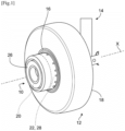
- FIG. 1 shows a device 10 for driving at least one wheel 12 of an aircraft landing gear 14.
- the device 10 comprises an electric motor 20 and a mechanical transmission system 22 between a shaft of the motor 20 and the rim 16 of the wheel 12.
- the motor 20 and the system 22 each have a generally annular shape and are centered on the X axis. They are arranged next to from each other and the system 22 is installed between the motor 20 and the rim 16. A part of the system 22, or even also a part of the motor 20, could be housed in the rim 16 to reduce the size of the device 10.
- the motor 20 and the system 22 can be protected by an external cylindrical cover 26 projecting on one side of the rim 16 or the tire 18.
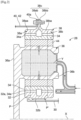
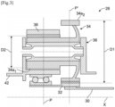
- the mechanical transmission system 22 comprises a mechanical speed reducer 28, examples of which are illustrated in figures 2 And 3 .
- the helix widths vary between the sun gear 32, the satellites 34 and the crown 38 because of the tooth overlaps, they are all centered on a median plane P for the upstream teeth and on another median plane P' for the downstream teeth.
- FIG. 2 thus illustrates the case of a single-stage gear reducer, i.e. the same toothing 34a of each satellite 34 cooperates with both the sun gear 32 and the crown wheel 38. Even if the toothing 34a comprises two sets of teeth, these teeth have the same average diameter and form a single set of teeth called a chevron.
- each satellite 34 comprises two separate teeth 34a1, 34a2 configured to cooperate respectively with the crown 38 and the sun gear 32.
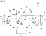
- FIG. 4 shows a first embodiment of a mechanical speed reducer 28 according to the invention which has the particularity of having a double epicyclic gear train.
- the solar 32 comprises a shaft 32c which can be that of the motor 20 or which can be connected to the shaft of the motor 20, and a pinion comprising at its external periphery the external toothing 32a.
- the reducer 28 is here of the double-stage type, that is to say that the first and second satellites 34, 46 are each here of the double-stage type and comprise two independent toothings 34a, 34b, 46a, 46b.
- the first planet carrier 36 comprises or carries physical axes 36b for supporting or even guiding the first satellites 34.
- the first planet carrier 36 further comprises a shaft 36c or a portion of shaft connected to a pinion comprising at its external periphery the external toothing 36a.
- the internal teeth 52, 54 are carried by the same crown 38. Alternatively, they could be carried by different crowns.
- the crown 38 is fixed and is therefore intended to be fixed to a stator of the device 10.
- the shafts 32c, 36c, 46c are centered and guided in rotation around the X axis by bearings 50.
- the teeth 34a, 34b, 32a are of any type and for example herringbone.
- the teeth 46a, 46b, 36a are of any type and preferably herringbone.
- the teeth 52, 54 are preferably helical.
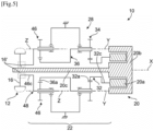
- FIG. 5 shows a device 10 for driving a wheel 12 of an aircraft landing gear, comprising the reducer 28 of the Figure 4 .
- the motor 20 of the device 10 comprises a rotor 20a and a stator 20b.
- the rotor 20a here has an annular shape and is connected to the shaft 32c.
- the stator 20b has an annular shape and extends around the rotor 20a and also on a side of the rotor 20a opposite the reduction gear 28.
- FIG. 6 shows an alternative embodiment of a device 10 for driving a wheel 12 of an aircraft landing gear according to the invention.
- teeth 32a and 34a are located in the same plane P1 perpendicular to the X axis.
- the teeth 34b and 52 are located in the same plane P2 perpendicular to the X axis.
- the teeth 46a and 36b are located in the same plane P3 perpendicular to the X axis.
- the teeth 46b and 54 are located in the same plane P4 perpendicular to the X axis.
- the crown 38 is arranged between the planes P1 and P3.
- the crown 38 has an external diameter D5 which defines the external diameter of the reducer 28 and which is preferably less than the external diameter D6 of the rim 16 so as to be able to axially house a part of the reducer 28 in the rim 16.
- FIGS. 7a and 7b show another alternative embodiment of a device 10 for driving a wheel 12 of an aircraft landing gear according to the invention.
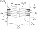
- FIG 8 shows an example of guidance of the satellites 34, 46 of the reducer 28.
- the satellites 34, 46 are guided by rolling bearings 45 which are here more particularly roller bearings.
- the guide bearings 45 of each satellite 34, 46 are two in number and are mounted around the longitudinal ends of this satellite, between these ends and the planet carrier 36, 48.
- Each of the bearings 45 comprises an internal ring 45a carried by the satellite 34, 46 or integrated into the latter, and an external ring 45b carried by the planet carrier 34, 48.
- the rollers 45c are mounted between the rings 45a, 45b.
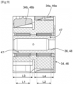
- the satellites 34, 46 are guided by needle bearings 47. These bearings 47 are two in number and are mounted radially inside the satellites 34, 46. Each of the bearings 47 is aligned radially with one of the teeth 34a, 46a of the satellite 34, 46. This assembly makes it possible to reduce the axial size.
- Each of the bearings 47 may have an axial length or dimension L1, L2 measured along the Y or Z axis, which represents at least 80% of the axial length or dimension L3, L4 of the corresponding toothing 34a, 46a.
- the guide bearings of the satellites 34, 46 are plain bearings or hydrodynamic bearings.
Landscapes
- Engineering & Computer Science (AREA)
- Mechanical Engineering (AREA)
- General Engineering & Computer Science (AREA)
- Aviation & Aerospace Engineering (AREA)
- Chemical & Material Sciences (AREA)
- Combustion & Propulsion (AREA)
- Transportation (AREA)
- Retarders (AREA)
Description
La présente invention concerne un réducteur mécanique de vitesse ainsi qu'un dispositif d'entraînement d'au moins une roue d'un train d'atterrissage d'aéronef comportant un tel réducteur.The present invention relates to a mechanical speed reducer as well as a device for driving at least one wheel of an aircraft landing gear comprising such a reducer.
L'arrière-plan technique comprend notamment les documents
Un aéronef comprend des trains d'atterrissage équipés de roues pour les déplacements de l'aéronef au sol sur un tarmac. Ce roulage aussi appelé taxiage (de l'anglais taxiing) peut être obtenu en propulsant l'aéronef grâce à ses turbomachines.An aircraft has landing gear equipped with wheels for moving the aircraft on the ground on a tarmac. This rolling, also called taxiing, can be achieved by propelling the aircraft using its turbomachinery.
Pour limiter la consommation de carburant et l'impact sur l'environnement, il est connu de réaliser ce taxiage de manière électrique. Le taxiage électrique est obtenu en entraînant les roues d'un train d'atterrissage par un moteur électrique.To limit fuel consumption and environmental impact, it is known to perform this taxiing electrically. Electric taxiing is achieved by driving the wheels of a landing gear with an electric motor.
La présente demande propose un perfectionnement aux technologies existantes et concerne ainsi un dispositif à moteur électrique pour l'entraînement d'au moins une roue d'un train d'atterrissage d'aéronef.The present application proposes an improvement to existing technologies and thus relates to an electric motor device for driving at least one wheel of an aircraft landing gear.
Une solution consistant à utiliser un réducteur mécanique pour transmettre la puissance d'un moteur électrique à une roue d'un train d'atterrissage a été proposée par la Demanderesse dans le document
Le rôle d'un réducteur mécanique est de modifier le rapport de vitesse et de couple entre l'axe d'entrée et l'axe de sortie d'un système mécanique.The role of a mechanical reducer is to modify the speed and torque ratio between the input shaft and the output shaft of a mechanical system.
Dans le domaine éloigné des turbomachines d'aéronef, il est connu d'utiliser un réducteur mécanique pour assurer une transmission de puissance entre deux arbres mécaniques rotatifs.In the distant field of aircraft turbomachinery, it is known to use a mechanical reducer to ensure power transmission between two rotating mechanical shafts.
Il existe de nombreux types de réducteurs par exemple différentiels, planétaires, épicycloïdaux, à lignes intermédiaires, à étages de réduction en série, etc.There are many types of reducers, for example differential, planetary, epicyclic, intermediate line, series reduction stages, etc.
Dans l'état de l'art des turbomachines à double flux, les réducteurs sont de type planétaire ou épicycloïdal. Un tel réducteur comprend un pignon central, appelé solaire, une couronne et des pignons appelés satellites, qui sont en prise entre le solaire et la couronne. Les satellites sont maintenus par un châssis appelé porte-satellites. Le solaire, la couronne et le porte-satellites sont des planétaires car leurs axes de révolution coïncident avec l'axe longitudinal de la turbomachine. Les satellites ont chacun un axe de révolution différents équirépartis sur le même diamètre de fonctionnement autour de l'axe des planétaires. Ces axes sont parallèles à l'axe longitudinal de la turbomachine.In the state of the art of turbofan engines, the gearboxes are planetary or epicyclic. Such a gearbox comprises a central pinion, called a sun gear, a crown gear and pinions called planet gears, which are meshed between the sun gear and the crown gear. The planet gears are held by a frame called a planet carrier. The sun gear, the crown gear and the planet carrier are planet gears because their axes of revolution coincide with the longitudinal axis of the turbomachine. The planet gears each have a different axis of revolution equally distributed over the same operating diameter around the axis of the planet gears. These axes are parallel to the longitudinal axis of the turbomachine.
Il existe plusieurs architectures de réducteur. Il existe dans d'autres applications similaires, des architectures dites différentielles ou « compound ».
- Sur un réducteur planétaire, le porte-satellites est fixe et la couronne constitue l'arbre de sortie du dispositif qui tourne dans le sens inverse du solaire.
- Sur un réducteur épicycloïdal, la couronne est fixe et le porte-satellites constitue l'arbre de sortie du dispositif qui tourne dans le même sens que le solaire.
- Sur un réducteur différentiel, aucun élément n'est fixé en rotation. La couronne tourne dans le sens contraire du solaire et du porte-satellites.
- On a planetary gearbox, the planet carrier is fixed and the crown constitutes the output shaft of the device which rotates in the opposite direction to the solar.
- On an epicyclic reducer, the crown is fixed and the planet carrier constitutes the output shaft of the device which rotates in the same direction as the sun.
- In a differential gearbox, no element is fixed in rotation. The crown rotates in the opposite direction to the sun gear and the planet carrier.
Les réducteurs peuvent être composés d'un ou plusieurs étages d'engrènement. Cet engrènement est assuré de différentes façons comme par contact, par friction ou encore par champs magnétique.Gearboxes can be composed of one or more meshing stages. This meshing is ensured in different ways such as by contact, friction or even magnetic fields.
Dans la présente demande, on entend par « étage » ou « denture », au moins une série de dents d'engrènement avec au moins une série de dents complémentaires. Une denture peut être interne ou externe.In this application, the term "stage" or "teeth" means at least one series of meshing teeth with at least one series of complementary teeth. A toothing may be internal or external.
Un satellite peut comprendre un ou deux étages d'engrènement. Un satellite à simple étage comprend une denture qui peut être droite, hélicoïdale ou en chevron et dont les dents sont situées sur un même diamètre. Cette denture coopère à la fois avec le solaire et la couronne.A satellite can have one or two meshing stages. A single-stage satellite has a toothing that can be straight, helical, or herringbone, and whose teeth are located on the same diameter. This toothing cooperates with both the sun gear and the crown.
Un satellite à double étage comprend deux dentures qui sont situées sur des diamètres différents. Une première denture coopère avec le solaire et une seconde denture coopère en général avec la couronne.A double-stage satellite consists of two sets of teeth that are located on different diameters. One set of teeth cooperates with the sun gear and a second set of teeth generally cooperates with the crown.
Un réducteur à double étage d'engrènement présente l'avantage d'avoir un rapport de réduction plus important qu'un réducteur à simple étage d'engrènement de même encombrement.A double-stage gear reducer has the advantage of having a higher reduction ratio than a single-stage gear reducer of the same size.
Dans le cadre d'un dispositif d'entraînement d'au moins une roue d'un train d'atterrissage, l'utilisation d'un moteur électrique et d'un réducteur pour l'entraînement de la roue génère de fortes contraintes d'encombrement. Le diamètre extérieur du réducteur est limité par la dimension de la jante de la roue, et le diamètre intérieur du réducteur est fortement contraint par le diamètre du moyeu de la roue. De plus, l'utilisation d'un moteur électrique tournant généralement à des vitesses élevées nécessite l'utilisation d'un réducteur proposant un grand rapport de réduction afin de proposer une vitesse de sortie qui correspond à la faible vitesse de rotation de la roue. Les trains de type épicycloïdal et planétaire de la technique actuelle ne permettent pas d'obtenir ces niveaux de réduction dans un encombrement aussi restreint.In the context of a device for driving at least one wheel of a landing gear, the use of an electric motor and a reduction gear for driving the wheel generates significant space constraints. The outer diameter of the reduction gear is limited by the dimension of the wheel rim, and the inner diameter of the reduction gear is strongly constrained by the diameter of the wheel hub. In addition, the use of an electric motor generally rotating at high speeds requires the use of a reduction gear offering a large reduction ratio in order to provide an output speed that corresponds to the low rotational speed of the wheel. The epicyclic and planetary gears of current technology do not allow these levels of reduction to be obtained in such a restricted space.
L'invention propose une solution à au moins une partie de ces problèmes, qui est simple, efficace et économique.The invention provides a solution to at least some of these problems, which is simple, effective and economical.
L'invention concerne un réducteur mécanique de vitesse, en particulier pour un dispositif d'entraînement d'au moins une roue d'un train d'atterrissage d'aéronef, ce réducteur comportant :
- un premier solaire mobile en rotation autour d'un axe X et comportant une denture externe,
- des premiers satellites répartis autour de l'axe X et engrenés avec la denture externe du premier solaire, ces premiers satellites étant mobiles en rotation autour d'axes Y parallèles à l'axe X et étant portés par un premier porte-satellites mobile en rotation autour de l'axe X,
- une couronne fixe engrenée avec les satellites,
- des seconds satellites répartis autour de l'axe X et engrenés avec une couronne et avec une denture externe dudit premier porte-satellites, ces seconds satellites étant mobiles en rotation autour d'axes Z parallèles à l'axe X et étant portés par un second porte-satellites mobile en rotation autour de l'axe X.
- a first mobile solar rotating around an X axis and comprising external teeth,
- first satellites distributed around the X axis and meshed with the external teeth of the first sun gear, these first satellites being mobile in rotation around Y axes parallel to the X axis and being carried by a first satellite carrier mobile in rotation around the X axis,
- a fixed crown meshed with the satellites,
- second satellites distributed around the X axis and meshed with a crown and with external teeth of said first planet carrier, these second satellites being mobile in rotation around Z axes parallel to the X axis and being carried by a second planet carrier mobile in rotation around the X axis.
L'invention propose ainsi un réducteur à double train épicycloïdal. Un premier train épicycloïdal est formé par le premier solaire, les premiers satellites portés par le premier porte-satellites et la couronne. Un second train épicycloïdal est formé par le premier porte-satellites qui forme un second solaire, les seconds satellites portés par le second porte-satellites, et la couronne. On comprend donc qu'il y a un élément en commun aux deux trains épicycloïdaux et qui assurent le lien entre ces deux trains, il s'agit du premier porte-satellites pour le premier train et le second solaire pour le second train. En pratique, cela peut revenir à équiper le premier porte-satellites avec une denture externe de pignon qui est centrée sur l'axe X et qui peut engrener avec les dentures des seconds satellites. Les couronnes du premier et second trains peuvent être communes ou différentes.The invention thus proposes a double epicyclic gear train reducer. A first epicyclic gear train is formed by the first sun gear, the first satellites carried by the first planet carrier and the crown. A second epicyclic gear train is formed by the first planet carrier which forms a second sun gear, the second satellites carried by the second planet carrier, and the crown. It is therefore understood that there is an element in common to the two epicyclic gear trains and which ensures the link between these two trains, it is the first planet carrier for the first train and the second sun gear for the second train. In practice, this can amount to equipping the first planet carrier with an external pinion toothing which is centered on the X axis and which can mesh with the teeth of the second satellites. The crowns of the first and second trains can be common or different.
Le réducteur comprend ainsi le premier solaire qui forme l'entrée du réducteur et le second porte-satellites qui forme la sortie du réducteur. La ou les couronnes est/sont fixe(s).The reducer thus comprises the first sun gear which forms the input of the reducer and the second planet carrier which forms the output of the reducer. The crown(s) is/are fixed.
Les satellites sont avantageusement du type à double étage et comprennent ainsi des dentures indépendantes pour l'engrènement avec le solaire et la couronne. Le réducteur est alors dans ce cas du type à double train épicycloïdal et double étage.The satellites are advantageously of the double-stage type and thus include independent teeth for meshing with the sun gear and the crown. The reducer is then in this case of the double epicyclic train and double-stage type.
Le réducteur selon l'invention a un grand rapport de réduction par rapport aux réducteurs de la technique antérieure, grâce à son double train épicycloïdal.The reducer according to the invention has a large reduction ratio compared to the reducers of the prior art, thanks to its double epicyclic gear train.
L'invention est compatible d'un réducteur à plusieurs étages comme évoqué dans ce qui précède. Elle est également compatible d'un réducteur dont le porte-satellites est mobile en rotation comme les réducteurs épicycloïdaux ou différentiels. Elle est également compatible avec des dentures de n'importe quel type (droites, hélicoïdales, chevrons, etc.). L'invention est en outre compatible avec un porte-satellites de type monobloc ou de type cage et porte-cage. Ces différents types de réducteur sont bien connus de l'homme du métier. La solution proposée ci-dessous est compatible de tout type de palier satellite, qu'il soit composé d'éléments roulants, d'un palier hydrodynamique, etc.The invention is compatible with a multi-stage reducer as mentioned above. It is also compatible with a reducer whose planet carrier is rotatable such as epicyclic or differential reducers. It is also compatible with teeth of any type (straight, helical, chevron, etc.). The invention is furthermore compatible with a planet carrier of the monobloc type or of the cage and cage carrier type. These different types of reducer are well known to those skilled in the art. The solution proposed below is compatible with any type of satellite bearing, whether it is composed of rolling elements, a hydrodynamic bearing, etc.
Selon la revendication 1, le réducteur comprend les caractéristiques suivantes:
- les premiers satellites comportent chacun une première denture externe engrenée avec la denture externe du premier solaire, et une seconde denture externe engrenée avec une première denture interne d'une première couronne ;
- les première et seconde dentures de chacun des premiers satellites ont des diamètres différents et/ou des nombres de dents différents ;
- les seconds satellites comportent chacun une première denture externe engrenée avec la denture externe du premier porte-satellites ;
- les seconds satellites comportent chacun une seconde denture externe engrenée avec une seconde denture interne de ladite première couronne ;
- les première et seconde dentures de chacun des seconds satellites ont des diamètres différents et/ou des nombres de dents différents.
- the first satellites each comprise a first external toothing meshed with the external toothing of the first sun gear, and a second external toothing meshed with a first internal toothing of a first crown;
- the first and second teeth of each of the first satellites have different diameters and/or different numbers of teeth;
- the second satellites each comprise a first external toothing meshed with the external toothing of the first planet carrier;
- the second satellites each comprise a second external toothing meshed with a second internal toothing of said first crown;
- the first and second teeth of each of the second satellites have different diameters and/or different numbers of teeth.
En outre, le réducteur selon l'invention peut comprendre une ou plusieurs des caractéristiques suivantes, prises isolément les unes des autres, ou en combinaison les unes avec les autres :
- les axes Y sont situés sur une première circonférence et les axes Z sont situés sur une seconde circonférence, les première et seconde circonférences ayant des diamètres différents ;
- les axes Y sont situés sur une première circonférence et les axes Z sont situés sur une seconde circonférence, les première et seconde circonférences ayant des diamètres identiques ;
- le nombre de premiers satellites est égal au nombre de seconds satellites ;
- le nombre de premiers satellites est différent du nombre de seconds satellites ;
- les dentures des premiers et seconds satellites sont en chevron et les dentures de la ou des couronne(s) sont en hélice ;
- les premiers et seconds satellites sont guidés en rotation par des paliers qui sont situés aux extrémités longitudinales des satellites ou radialement à l'intérieur des dentures de ces satellites.
- the Y axes are located on a first circumference and the Z axes are located on a second circumference, the first and second circumferences having different diameters;
- the Y axes are located on a first circumference and the Z axes are located on a second circumference, the first and second circumferences having identical diameters;
- the number of first satellites is equal to the number of second satellites;
- the number of first satellites is different from the number of second satellites;
- the teeth of the first and second satellites are chevron-shaped and the teeth of the crown(s) are helical;
- the first and second satellites are guided in rotation by bearings which are located at the longitudinal ends of the satellites or radially inside the teeth of these satellites.
La présente invention concerne encore un dispositif d'entraînement d'au moins une roue d'un train d'atterrissage d'aéronef, ce dispositif comportant :
- au moins une roue de train d'atterrissage, cette roue comportant une jante ayant un axe de rotation,
- un moteur électrique comportant un arbre,
- un système de transmission mécanique entre l'arbre du moteur et la jante, ce système de transmission mécanique comprenant un réducteur mécanique de vitesse tel que décrit ci-dessus.
- at least one landing gear wheel, this wheel comprising a rim having an axis of rotation,
- an electric motor comprising a shaft,
- a mechanical transmission system between the motor shaft and the rim, this mechanical transmission system comprising a mechanical speed reducer as described above.
D'autres caractéristiques et avantages ressortiront de la description qui suit d'un mode de réalisation non limitatif de l'invention en référence aux dessins annexés sur lesquels :
- [
Fig.1 ] lafigure 1 est une vue schématique en perspective d'une roue d'un train d'atterrissage d'aéronef et d'un dispositif d'entraînement de cette roue, - [
Fig.2 ] lafigure 2 est une vue partielle en coupe axiale d'un réducteur mécanique, - [
Fig.3 ] lafigure 3 est une autre vue partielle en coupe axiale d'un réducteur mécanique, - [
Fig.4 ] lafigure 4 est une vue schématique en coupe axiale d'un réducteur selon un mode de réalisation de l'invention, - [
Fig.5 ] lafigure 5 est une vue schématique en coupe axiale d'un dispositif d'entraînement d'une roue d'un train d'atterrissage d'aéronef, ce dispositif comportant le réducteur de lafigure 4 ; - [
Fig.6 ] lafigure 6 est une vue schématique en coupe axiale d'un dispositif d'entraînement d'une roue d'un train d'atterrissage d'aéronef, ce dispositif comportant un réducteur selon une variante de réalisation de l'invention, - [
Fig.7a-7b ] lesfigures 7a et 7b sont des vues schématiques, respectivement en perspective et en transparence d'une part, et en coupe axiale d'autre part, d'une autre variante de réalisation du réducteur selon l'invention ; - [
Fig.8 ] lafigure 8 est une vue schématique en coupe axiale d'un satellite et de paliers de guidage de ce satellite ; et - [
Fig.9 ] lafigure 9 est vue schématique en coupe axiale d'un satellite et de paliers de guidage de ce satellite.
- [
Fig. 1 ] thereFigure 1 is a schematic perspective view of a wheel of an aircraft landing gear and a device for driving this wheel, - [
Fig.2 ] thereFigure 2 is a partial axial sectional view of a mechanical reducer, - [
Fig. 3 ] thereFigure 3 is another partial axial sectional view of a mechanical reducer, - [
Fig.4 ] thereFigure 4 is a schematic axial sectional view of a reducer according to one embodiment of the invention, - [
Fig.5 ] thereFigure 5 is a schematic axial sectional view of a device for driving a wheel of an aircraft landing gear, this device comprising the reduction gear of theFigure 4 ; - [
Fig.6 ] thereFigure 6 is a schematic axial sectional view of a device for driving a wheel of an aircraft landing gear, this device comprising a reducer according to an alternative embodiment of the invention, - [
Fig.7a-7b ] THEFigures 7a and 7b are schematic views, respectively in perspective and in transparency on the one hand, and in axial section on the other hand, of another variant embodiment of the reducer according to the invention; - [
Fig.8 ] therefigure 8 is a schematic axial sectional view of a satellite and guide bearings of this satellite; and - [
Fig.9 ] therefigure 9 is a schematic view in axial section of a satellite and of the guide bearings of this satellite.
La
La roue 12 comporte une jante 16 qui a un axe de rotation X. De manière classique, cette jante 16 a une forme générale tubulaire ou de disque et porte à sa périphérie un pneu 18.The
Le dispositif 10 comprend un moteur électrique 20 et un système de transmission mécanique 22 entre un arbre du moteur 20 et la jante 16 de la roue 12.The
Dans l'exemple représenté, le moteur 20 et le système 22 ont chacun une forme générale annulaire et sont centrés sur l'axe X. Ils sont disposés à côté l'un de l'autre et le système 22 est installé entre le moteur 20 et la jante 16. Une partie du système 22, voire également une partie du moteur 20, pourraient être logées dans la jante 16 pour réduire l'encombrement du dispositif 10. Le moteur 20 et le système 22 peuvent être protégés par un capot cylindrique extérieur 26 en saillie sur un côté de la jante 16 ou du pneu 18.In the example shown, the
Le système de transmission mécanique 22 comprend un réducteur mécanique de vitesse 28 dont des exemples de réalisation sont illustrés aux
La
L'ensemble des satellites 34 est maintenu par un châssis appelé porte-satellites 36. Chaque satellite 34 tourne autour de son propre axe Y, et engrène avec une couronne 38.The set of
En sortie nous avons :
- ▪ Dans cette configuration épicycloïdale, l'ensemble des
satellites 34 entraine en rotation le porte-satellite 36 autour de l'axe X.La couronne 38 est fixée à un stator via un porte-couronne 40 et le porte-satellites 36 est fixé à autre arbre 42. - ▪ Dans une autre configuration planétaire, l'ensemble des
satellites 34 est maintenu par un porte-satellites 36 qui est fixé à un stator. Chaque satellite entraine la couronne 38 qui est reliée à l'arbre 42 via un porte-couronne 40. - ▪ Dans une autre configuration différentielle, l'ensemble des
satellites 34 est maintenu par un porte-satellites 36 qui est relié à l'arbre 30. Chaquesatellite 34 entraine la couronne 38 qui est rapportée à l'arbre 42 via un porte-couronne 40.
- ▪ In this epicyclic configuration, the set of
satellites 34 drives theplanet carrier 36 in rotation around the X axis. Thecrown 38 is fixed to a stator via a crown carrier 40 and theplanet carrier 36 is fixed to anothershaft 42. - ▪ In another planetary configuration, the set of planet gears 34 is held by a
planet carrier 36 which is fixed to a stator. Each planet gear drives thecrown 38 which is connected to theshaft 42 via a crown carrier 40. - ▪ In another differential configuration, the set of
satellites 34 is held by aplanet carrier 36 which is connected to theshaft 30. Eachsatellite 34 drives thecrown 38 which is attached to theshaft 42 via a crown carrier 40.
Chaque satellite 34 est monté libre en rotation à l'aide d'un palier 44, par exemple de type roulement ou palier hydrodynamique. Chaque palier 44 est monté sur un des axes 36b du porte-satellites 36 et tous les axes 36b sont positionnés les uns par rapport aux autres à l'aide d'un ou plusieurs châssis structurels 36a du porte-satellites 36. Il existe un nombre d'axes 36b et de paliers 44 égal au nombre de satellites 34. Pour des raisons de fonctionnement, de montage, de fabrication, de contrôle, de réparation ou de rechange, les axes 36b et le châssis 36a peuvent être séparés en plusieurs pièces.Each
Pour les mêmes raisons citées précédemment, la denture 34a d'un satellite 34 peut être séparée en plusieurs hélices ou dents présentant chacun un plan médian P, P'. Dans l'exemple représenté, chaque satellite 34 comprend deux séries de dents en chevron coopérant avec une couronne 38 séparée en deux demi-couronnes :
- ▪ Un anneau amont 38a constituée d'une jante 38aa et d'une demi-bride de fixation 38ab. Sur la jante 38aa se trouve l'hélice avant engrenée avec une hélice de la
denture 34a de chaquesatellite 34. L'hélice de ladenture 34a engrène également avec celle du solaire 32. - ▪
Un anneau aval 38b constituée d'une jante 38ba et d'une demi-bride de fixation 38bb. Sur la jante 38ba se trouve l'hélice arrière engrenée avec une hélice de ladenture 34a de chaquesatellite 34. L'hélice de ladenture 34a engrène également avec celle du solaire 32.
- ▪ An
upstream ring 38a consisting of a rim 38aa and a fixing half-flange 38ab. On the rim 38aa is the front propeller meshed with a propeller of thetoothing 34a of eachsatellite 34. The propeller of thetoothing 34a also meshes with that of thesun 32. - ▪ A
downstream ring 38b consisting of a rim 38ba and a half-fixing flange 38bb. On the rim 38ba is the rear propeller meshed with a propeller of thetoothing 34a of eachsatellite 34. The propeller of thetoothing 34a also meshes with that of thesun 32.
Si les largeurs d'hélice varient entre le solaire 32, les satellites 34 et la couronne 38 à cause des recouvrements de denture, elles sont toutes centrées sur un plan médian P pour les dents amont et sur un autre plan médian P' pour les dents aval.If the helix widths vary between the
La
La demi-bride de fixation 38ab de l'anneau amont 38a et la demi-bride de fixation 38bb de l'anneau aval 38b forment la bride de fixation 38c de la couronne. La couronne 38 est fixée au porte-couronne 40 en assemblant la bride de fixation 38c de la couronne 38 et une bride de fixation 40a du porte-couronne 40 à l'aide d'un montage boulonné par exemple.The fixing half-flange 38ab of the
La
Dans cette
La denture 34a1 d'engrènement avec la couronne 38 un diamètre moyen noté D2 et est situé dans un plan médian P. La denture 34a2 d'engrènement avec le solaire 32 a un diamètre moyen noté D1 et est situé dans un autre plan médian P'. Les plans médians P, P' sont parallèles entre eux et perpendiculaires à l'axe X. Le diamètre D2 est inférieur au diamètre D1. Enfin, chaque denture 34a1, 34a2 comprend ici une seule hélice.The toothing 34a1 meshing with the
La
Le réducteur 28 comprend
- un premier solaire 32 mobile en rotation autour d'un axe X et comportant une
denture externe 32a, des premiers satellites 34 répartis autour de l'axe X et engrenés avec ladenture externe 32a du premier solaire 32,ces premiers satellites 34 étant mobiles en rotation autour d'axes Y parallèles à l'axe X et étant portés par un premier porte-satellites 36 mobile en rotation autour de l'axe X, etune couronne 38 fixe engrenée avec lessatellites 34.
- a first solar 32 mobile in rotation around an axis X and comprising an
external toothing 32a, -
first satellites 34 distributed around the X axis and meshed with theexternal teeth 32a of thefirst sun gear 32, thesefirst satellites 34 being mobile in rotation around Y axes parallel to the X axis and being carried by afirst satellite carrier 36 mobile in rotation around the X axis, and - a fixed
crown 38 meshed with thesatellites 34.
Le réducteur 28 comprend en outre :
des seconds satellites 46 répartis autour de l'axe X et engrenés avec une couronne 38 et avec unedenture externe 36a du premier porte-satellites 36,ces seconds satellites 46 étant mobiles en rotation autour d'axes Z parallèles à l'axe X et étant portés par un second porte-satellites 48 mobile en rotation autour de l'axe X.
-
second satellites 46 distributed around the X axis and meshed with acrown 38 and withexternal teeth 36a of thefirst planet carrier 36, thesesecond satellites 46 being movable in rotation around axes Z parallel to the X axis and being carried by asecond planet carrier 48 movable in rotation around the X axis.
Dans l'exemple représenté, le solaire 32 comprend un arbre 32c qui peut être celui du moteur 20 ou qui peut être relié à l'arbre du moteur 20, et un pignon comportant à sa périphérie externe la denture externe 32a.In the example shown, the solar 32 comprises a
Le réducteur 28 est ici du type à double étage, c'est-à-dire que les premiers et seconds satellites 34, 46 sont chacun ici du type à double étage et comprend deux dentures 34a, 34b, 46a, 46b indépendantes.The
Les premiers satellites 34 comprennent une première denture 34a engrenée avec la denture 32a du solaire 32, et une seconde denture 34b engrenée avec une première denture 52 de la couronne 38. La première denture 34a a ici un diamètre et/ou un nombre de dents supérieur à celui de la seconde denture 34b. La denture 34a est située du côté de l'arbre 32c et donc du moteur électrique 20, et la denture 34b est donc située du côté opposé, c'est-à-dire du côté de la roue 12.The
Le premier porte-satellites 36 comprend ou porte des axes physiques 36b de support voire de guidage des premiers satellites 34. Le premier porte-satellites 36 comprend en outre un arbre 36c ou une portion d'arbre relié à un pignon comportant à sa périphérie externe la denture externe 36a.The
Les seconds satellites 46 comprennent une première denture 46a engrenée avec la denture 36a du premier porte-satellites 36 formant un second solaire, et une seconde denture 46b engrenée avec une seconde denture 54 de la couronne 38. La première denture 46a a ici un diamètre et/ou un nombre de dents supérieur à celui de la seconde denture 46b. La denture 46a est située du côté de la roue 12, et la denture 46b est donc située du côté opposé, c'est-à-dire du côté du moteur 20.The
Dans l'exemple représenté, les dentures internes 52, 54 sont portées par une même couronne 38. En variante, elles pourraient être portées par des couronnes différentes. La couronne 38 est fixe est donc destinée à être fixée à un stator du dispositif 10.In the example shown, the
Le second porte-satellites 48 comprend ou portent des axes physiques 48b de support voire de guidage des seconds satellites 46. Le second porte-satellites 48 comprend en outre un arbre 46c ou une portion d'arbre qui est destiné à être relié à la jante 16 de la roue 12.The
Comme on le voit à la
Les axes Y et Z sont ici situés respectivement sur des circonférences C1, C2 de même diamètre D3, D4. En variante, les diamètres D3, D4 de ces circonférences C1, C2 pourraient être différents.The Y and Z axes are here located respectively on circumferences C1, C2 of the same diameter D3, D4. Alternatively, the diameters D3, D4 of these circumferences C1, C2 could be different.
Les dentures 34a, 34b, 32a sont de n'importe quel type et par exemple en chevron. Les dentures 46a, 46b, 36a sont de n'importe quel type et de préférence en chevron. Les dentures 52, 54 sont de préférence en hélice.The
La
Le moteur 20 du dispositif 10 comprend un rotor 20a et un stator 20b. Le rotor 20a a ici une forme annulaire et est relié à l'arbre 32c. Le stator 20b a une forme annulaire et s'étend autour du rotor 20a et aussi sur un côté du rotor 20a opposé au réducteur 28.The
L'arbre 46c est relié à la jante 16 de la roue 12. Cette liaison peut être faite par un système de débrayage 16' qui est apte à adopter deux positions : une première position dans laquelle l'arbre de sortie du réducteur 28, et en particulier l'arbre 56c, est accouplé à la jante 16 ou à l'arbre de la jante, et une seconde position dans laquelle cet arbre de sortie est désaccouplé de la jante 16 qui est alors en roue libre.The
Le stator 20b du moteur 20 comprend une tige 20c qui est centrée sur l'axe X et qui s'étend le long de l'axe X en traversant successivement le réducteur 28 et la jante 16.The
La
La description qui précède faite en relation avec les
On constate à la
Les dentures 46a et 36b sont situées dans un même plan P3 perpendiculaire à l'axe X. Les dentures 46b et 54 sont situées dans un même plan P4 perpendiculaire à l'axe X.The
La couronne 38 est disposée entre les plans P1 et P3. La couronne 38 a un diamètre externe D5 qui définit le diamètre externe du réducteur 28 et qui est de préférence inférieur au diamètre externe D6 de la jante 16 de façon à pouvoir loger axialement une partie du réducteur 28 dans la jante 16.The
Les
La description qui précède faite en relation avec les
On constate que le nombre de premiers satellites 34, qui est ici de huit, est supérieur au nombre de seconds satellites 46, qui est ici de cinq.We note that the number of
La
On constate dans la
En variante et comme représenté à la
Chacun des paliers 47 peut avoir une longueur ou dimension axiale L1, L2 mesurée le long de l'axe Y ou Z, qui représente au moins 80% de la longueur ou dimension axiale L3, L4 de la denture 34a, 46a correspondante.Each of the
Dans encore une autre variante non représentée, les paliers de guidage des satellites 34, 46 sont des paliers lisses ou paliers hydrodynamiques.In yet another variant not shown, the guide bearings of the
Le réducteur 28 tel que décrit dans ce qui précède permet un grand rapport de réduction par rapport aux réducteurs de la technique antérieure, et a un faible encombrement, ces deux paramètres étant importants pour l'utilisation de ce réducteur dans un dispositif d'entraînement d'au moins une roue d'un train d'atterrissage d'aéronef.The
Claims (8)
- A mechanical speed reducer (28) for a device (10) for driving at least one wheel (12) of an aircraft landing gear (14), this reducer comprising:- a first sun gear (32) movable in rotation about an axis X and comprising an external toothing (32a),- first planet gears (34) distributed around the axis X and meshed with the external toothing (32a) of the first sun gear (32), these first planet gears (34) being movable in rotation around axes Y parallel to the axis X and being carried by a first planet carrier (36) movable in rotation around the axis X,- a stationary ring gear (38) meshed with the planet gears (34),- second planet gears (46) distributed around the axis X and meshed with the ring gear (38) and with an external toothing (36a) of said first planet carrier (36), these second planet gears (46) being movable in rotation around axes Z parallel to the axis X and being carried by a second planet carrier (48) movable in rotation around the axis X,wherein:- the first planet gears (34) each comprise a first external toothing (34a) meshed with the external toothing (32a) of the first sun gear (32), and the second planet gears (46) each comprise a first external toothing (46a) meshed with the external toothing (36a) of the first planet carrier (36),characterized in that the first planet gears (34) further comprise a second external toothing (34b) meshed with a first internal toothing (52) of the ring gear (38), the first and second toothings (34a, 34b) of each of the first planet gears (34) having different diameters and/or different numbers of teeth, and in that the second planet gears (46) further comprise a second external toothing (46a) meshed with a second internal toothing (54) of said ring gear (38), the first and second toothings (46a, 46b) of each of the second planet gears (34, 46) having different diameters and/or different numbers of teeth.
- The reducer (28) according to claim 1, wherein the axes Y are located on a first circumference (C1) and the axes Z are located on a second circumference (C2), the first and second circumferences (C1, C2) having different diameters (D1, D2).
- The reducer (28) according to claim 1, wherein the axes Y are located on a first circumference (C1) and the axes Z are located on a second circumference (C2), the first and second circumferences (C1, C2) having identical diameters (D1, D2).
- The reducer (28) according to one of the preceding claims, wherein the number of first planet gears (34) is equal to the number of second planet gears (46).
- The reducer (28) according to one of claims 1 to 3, wherein the number of first planet gears (34) is different from the number of second planet gears (46).
- The reducer (28) according to one of the preceding claims, wherein the toothings (34a, 34b, 46a, 46b) of the first and second planet gears (34, 46) are herringbone-shaped and the toothings (52, 54) of the ring gear (38) are helical.
- The reducer (28) according to one of the preceding claims, wherein the first and second planet gears (34, 46) are guided in rotation by bearings (45, 47) which are located at the longitudinal ends of the planet gears (34, 46) or radially inside the toothings (34a, 34b, 46a, 46b) of these planet gears.
- A device (10) for driving at least one wheel (12) of an aircraft landing gear, this device comprising:- at least one landing gear wheel (12), this wheel (12) comprising a rim (16) having an axis of rotation (X),- an electric motor (20) comprising a shaft,- a mechanical transmission system (22) between the shaft of the motor (20) and the rim (16), this mechanical transmission system (22) comprising a mechanical speed reducer (28) according to one of the preceding claims.
Applications Claiming Priority (1)
| Application Number | Priority Date | Filing Date | Title |
|---|---|---|---|
| FR2209339A FR3139797B1 (en) | 2022-09-16 | 2022-09-16 | SPEED REDUCER FOR A DRIVE DEVICE FOR A WHEEL OF AN AIRCRAFT LANDING GEAR |
Publications (2)
| Publication Number | Publication Date |
|---|---|
| EP4339099A1 EP4339099A1 (en) | 2024-03-20 |
| EP4339099B1 true EP4339099B1 (en) | 2025-06-25 |
Family
ID=84331048
Family Applications (1)
| Application Number | Title | Priority Date | Filing Date |
|---|---|---|---|
| EP23196315.8A Active EP4339099B1 (en) | 2022-09-16 | 2023-09-08 | Speed reducer for a device for driving a wheel of an aircraft landing gear |
Country Status (3)
| Country | Link |
|---|---|
| US (1) | US12391373B2 (en) |
| EP (1) | EP4339099B1 (en) |
| FR (1) | FR3139797B1 (en) |
Families Citing this family (1)
| Publication number | Priority date | Publication date | Assignee | Title |
|---|---|---|---|---|
| FR3161413B1 (en) | 2024-04-23 | 2026-04-03 | Safran Trans Systems | DRIVE DEVICE FOR AT LEAST ONE WHEEL OF AN AIRCRAFT LANDING GEAR |
Family Cites Families (10)
| Publication number | Priority date | Publication date | Assignee | Title |
|---|---|---|---|---|
| GB1290501A (en) * | 1969-10-13 | 1972-09-27 | ||
| US6966865B2 (en) * | 2003-11-10 | 2005-11-22 | The Boeing Company | High ratio, reduced size epicyclic gear transmission for rotary wing aircraft with improved safety and noise reduction |
| FR3022858B1 (en) | 2014-06-30 | 2018-01-05 | Compagnie Generale Des Etablissements Michelin | WHEEL MOTORIZATION SYSTEM, IN PARTICULAR AN AIRCRAFT |
| EP3193040A1 (en) * | 2016-01-12 | 2017-07-19 | Goodrich Actuation Systems SAS | Planetary gear assembly |
| GB2562246B (en) * | 2017-05-09 | 2019-09-25 | Rolls Royce Plc | A Geared gas turbine engine |
| US20190191575A1 (en) | 2017-12-14 | 2019-06-20 | Keisha Tawn Lavergne | Fire and water resistant ankle monitor |
| AU2019201928B2 (en) * | 2018-03-23 | 2020-10-22 | Wheeltug plc | Epicyclic gearbox |
| EP3599391A1 (en) * | 2018-07-23 | 2020-01-29 | Flender GmbH | Crank drive for wind power plants and industrial applications |
| DE102018222005A1 (en) * | 2018-12-18 | 2020-06-18 | Zf Friedrichshafen Ag | Wheel hub gear for a single wheel drive of a motor vehicle |
| FR3108308B1 (en) | 2020-03-19 | 2024-01-19 | Safran Trans Systems | DEVICE FOR DRIVING AT LEAST ONE WHEEL OF AN AIRCRAFT LANDING GEAR |
-
2022
- 2022-09-16 FR FR2209339A patent/FR3139797B1/en active Active
-
2023
- 2023-09-08 EP EP23196315.8A patent/EP4339099B1/en active Active
- 2023-09-13 US US18/466,330 patent/US12391373B2/en active Active
Also Published As
| Publication number | Publication date |
|---|---|
| US12391373B2 (en) | 2025-08-19 |
| FR3139797A1 (en) | 2024-03-22 |
| EP4339099A1 (en) | 2024-03-20 |
| US20240092479A1 (en) | 2024-03-21 |
| FR3139797B1 (en) | 2024-10-25 |
Similar Documents
| Publication | Publication Date | Title |
|---|---|---|
| EP3922886B1 (en) | Mechanical gear for aircraft turbine engine | |
| EP3726031B1 (en) | Mechanical gear for aircraft turbine engine | |
| EP4001619B1 (en) | Mechanical gear for aircraft turbine engine | |
| EP3922831B1 (en) | Mechanical gear for aircraft turbine engine | |
| EP3995681B1 (en) | Mechanical gear for aircraft turbine engine | |
| EP3992494B1 (en) | Mechanical gear for aircraft turbine engine | |
| EP4303468B1 (en) | Sun gear for a reduction gearbox of an aircraft turbine engine | |
| EP4290097A1 (en) | Planet carrier for a mechanical gearbox of an aircraft turbomachine | |
| EP4382769B1 (en) | Ring gear for an aircraft mechanical gear | |
| EP4151846A1 (en) | Aircraft turbine engine | |
| EP4339099B1 (en) | Speed reducer for a device for driving a wheel of an aircraft landing gear | |
| EP4339097B1 (en) | Device for driving at least one wheel of an aircraft landing gear | |
| EP4033086B1 (en) | Turbine engine for aircraft with triple flow provided with a power transmission module | |
| EP4339098B1 (en) | Device for driving at least one wheel of an aircraft landing gear | |
| EP4689448A1 (en) | Moving ring gear for a mechanical reduction gear of an aircraft | |
| WO2025109268A1 (en) | Device for driving at least one wheel of an aircraft landing gear | |
| FR3161413A1 (en) | DRIVE DEVICE FOR AT LEAST ONE WHEEL OF AN AIRCRAFT LANDING GEAR | |
| EP4242489B1 (en) | Mechanical reduction gear for an aircraft turbine engine | |
| EP4339484A1 (en) | Aircraft turbine engine with mechanical reduction gear | |
| EP4689447A1 (en) | Assembly for a mechanical reducer of an aircraft | |
| WO2024209160A1 (en) | Fixed casing for a mechanical reducer of an aircraft | |
| EP4471295A1 (en) | Solar for a mechanical gear of an aircraft turbine engine | |
| WO2024261427A1 (en) | Aircraft twin-propeller turbine engine | |
| WO2025109264A1 (en) | Geared motor for an aircraft |
Legal Events
| Date | Code | Title | Description |
|---|---|---|---|
| PUAI | Public reference made under article 153(3) epc to a published international application that has entered the european phase |
Free format text: ORIGINAL CODE: 0009012 |
|
| STAA | Information on the status of an ep patent application or granted ep patent |
Free format text: STATUS: REQUEST FOR EXAMINATION WAS MADE |
|
| 17P | Request for examination filed |
Effective date: 20230908 |
|
| AK | Designated contracting states |
Kind code of ref document: A1 Designated state(s): AL AT BE BG CH CY CZ DE DK EE ES FI FR GB GR HR HU IE IS IT LI LT LU LV MC ME MK MT NL NO PL PT RO RS SE SI SK SM TR |
|
| GRAP | Despatch of communication of intention to grant a patent |
Free format text: ORIGINAL CODE: EPIDOSNIGR1 |
|
| STAA | Information on the status of an ep patent application or granted ep patent |
Free format text: STATUS: GRANT OF PATENT IS INTENDED |
|
| RIC1 | Information provided on ipc code assigned before grant |
Ipc: F16H 1/28 20060101ALI20250128BHEP Ipc: B64C 25/40 20060101AFI20250128BHEP |
|
| INTG | Intention to grant announced |
Effective date: 20250217 |
|
| GRAS | Grant fee paid |
Free format text: ORIGINAL CODE: EPIDOSNIGR3 |
|
| GRAA | (expected) grant |
Free format text: ORIGINAL CODE: 0009210 |
|
| STAA | Information on the status of an ep patent application or granted ep patent |
Free format text: STATUS: THE PATENT HAS BEEN GRANTED |
|
| AK | Designated contracting states |
Kind code of ref document: B1 Designated state(s): AL AT BE BG CH CY CZ DE DK EE ES FI FR GB GR HR HU IE IS IT LI LT LU LV MC ME MK MT NL NO PL PT RO RS SE SI SK SM TR |
|
| REG | Reference to a national code |
Ref country code: GB Ref legal event code: FG4D Free format text: NOT ENGLISH |
|
| REG | Reference to a national code |
Ref country code: CH Ref legal event code: EP |
|
| REG | Reference to a national code |
Ref country code: CH Ref legal event code: EP |
|
| REG | Reference to a national code |
Ref country code: IE Ref legal event code: FG4D Free format text: LANGUAGE OF EP DOCUMENT: FRENCH |
|
| REG | Reference to a national code |
Ref country code: DE Ref legal event code: R096 Ref document number: 602023004267 Country of ref document: DE |
|
| PG25 | Lapsed in a contracting state [announced via postgrant information from national office to epo] |
Ref country code: FI Free format text: LAPSE BECAUSE OF FAILURE TO SUBMIT A TRANSLATION OF THE DESCRIPTION OR TO PAY THE FEE WITHIN THE PRESCRIBED TIME-LIMIT Effective date: 20250625 |
|
| PGFP | Annual fee paid to national office [announced via postgrant information from national office to epo] |
Ref country code: DE Payment date: 20250919 Year of fee payment: 3 |
|
| REG | Reference to a national code |
Ref country code: LT Ref legal event code: MG9D |
|
| PG25 | Lapsed in a contracting state [announced via postgrant information from national office to epo] |
Ref country code: GR Free format text: LAPSE BECAUSE OF FAILURE TO SUBMIT A TRANSLATION OF THE DESCRIPTION OR TO PAY THE FEE WITHIN THE PRESCRIBED TIME-LIMIT Effective date: 20250926 Ref country code: NO Free format text: LAPSE BECAUSE OF FAILURE TO SUBMIT A TRANSLATION OF THE DESCRIPTION OR TO PAY THE FEE WITHIN THE PRESCRIBED TIME-LIMIT Effective date: 20250925 |
|
| PG25 | Lapsed in a contracting state [announced via postgrant information from national office to epo] |
Ref country code: BG Free format text: LAPSE BECAUSE OF FAILURE TO SUBMIT A TRANSLATION OF THE DESCRIPTION OR TO PAY THE FEE WITHIN THE PRESCRIBED TIME-LIMIT Effective date: 20250625 |
|
| PG25 | Lapsed in a contracting state [announced via postgrant information from national office to epo] |
Ref country code: HR Free format text: LAPSE BECAUSE OF FAILURE TO SUBMIT A TRANSLATION OF THE DESCRIPTION OR TO PAY THE FEE WITHIN THE PRESCRIBED TIME-LIMIT Effective date: 20250625 |
|
| PGFP | Annual fee paid to national office [announced via postgrant information from national office to epo] |
Ref country code: FR Payment date: 20250923 Year of fee payment: 3 Ref country code: AT Payment date: 20251020 Year of fee payment: 3 |
|
| PG25 | Lapsed in a contracting state [announced via postgrant information from national office to epo] |
Ref country code: RS Free format text: LAPSE BECAUSE OF FAILURE TO SUBMIT A TRANSLATION OF THE DESCRIPTION OR TO PAY THE FEE WITHIN THE PRESCRIBED TIME-LIMIT Effective date: 20250925 |
|
| PG25 | Lapsed in a contracting state [announced via postgrant information from national office to epo] |
Ref country code: LV Free format text: LAPSE BECAUSE OF FAILURE TO SUBMIT A TRANSLATION OF THE DESCRIPTION OR TO PAY THE FEE WITHIN THE PRESCRIBED TIME-LIMIT Effective date: 20250625 |
|
| REG | Reference to a national code |
Ref country code: NL Ref legal event code: MP Effective date: 20250625 |
|
| PG25 | Lapsed in a contracting state [announced via postgrant information from national office to epo] |
Ref country code: NL Free format text: LAPSE BECAUSE OF FAILURE TO SUBMIT A TRANSLATION OF THE DESCRIPTION OR TO PAY THE FEE WITHIN THE PRESCRIBED TIME-LIMIT Effective date: 20250625 |
|
| PG25 | Lapsed in a contracting state [announced via postgrant information from national office to epo] |
Ref country code: PT Free format text: LAPSE BECAUSE OF FAILURE TO SUBMIT A TRANSLATION OF THE DESCRIPTION OR TO PAY THE FEE WITHIN THE PRESCRIBED TIME-LIMIT Effective date: 20251027 |
|
| REG | Reference to a national code |
Ref country code: AT Ref legal event code: MK05 Ref document number: 1806239 Country of ref document: AT Kind code of ref document: T Effective date: 20250625 |
|
| PG25 | Lapsed in a contracting state [announced via postgrant information from national office to epo] |
Ref country code: IS Free format text: LAPSE BECAUSE OF FAILURE TO SUBMIT A TRANSLATION OF THE DESCRIPTION OR TO PAY THE FEE WITHIN THE PRESCRIBED TIME-LIMIT Effective date: 20251025 |
|
| PG25 | Lapsed in a contracting state [announced via postgrant information from national office to epo] |
Ref country code: SM Free format text: LAPSE BECAUSE OF FAILURE TO SUBMIT A TRANSLATION OF THE DESCRIPTION OR TO PAY THE FEE WITHIN THE PRESCRIBED TIME-LIMIT Effective date: 20250625 Ref country code: AT Free format text: LAPSE BECAUSE OF FAILURE TO SUBMIT A TRANSLATION OF THE DESCRIPTION OR TO PAY THE FEE WITHIN THE PRESCRIBED TIME-LIMIT Effective date: 20250625 |
|
| PG25 | Lapsed in a contracting state [announced via postgrant information from national office to epo] |
Ref country code: CZ Free format text: LAPSE BECAUSE OF FAILURE TO SUBMIT A TRANSLATION OF THE DESCRIPTION OR TO PAY THE FEE WITHIN THE PRESCRIBED TIME-LIMIT Effective date: 20250625 |
|
| PG25 | Lapsed in a contracting state [announced via postgrant information from national office to epo] |
Ref country code: PL Free format text: LAPSE BECAUSE OF FAILURE TO SUBMIT A TRANSLATION OF THE DESCRIPTION OR TO PAY THE FEE WITHIN THE PRESCRIBED TIME-LIMIT Effective date: 20250625 |
|
| PG25 | Lapsed in a contracting state [announced via postgrant information from national office to epo] |
Ref country code: EE Free format text: LAPSE BECAUSE OF FAILURE TO SUBMIT A TRANSLATION OF THE DESCRIPTION OR TO PAY THE FEE WITHIN THE PRESCRIBED TIME-LIMIT Effective date: 20250625 |
|
| PG25 | Lapsed in a contracting state [announced via postgrant information from national office to epo] |
Ref country code: SK Free format text: LAPSE BECAUSE OF FAILURE TO SUBMIT A TRANSLATION OF THE DESCRIPTION OR TO PAY THE FEE WITHIN THE PRESCRIBED TIME-LIMIT Effective date: 20250625 |
|
| PG25 | Lapsed in a contracting state [announced via postgrant information from national office to epo] |
Ref country code: ES Free format text: LAPSE BECAUSE OF FAILURE TO SUBMIT A TRANSLATION OF THE DESCRIPTION OR TO PAY THE FEE WITHIN THE PRESCRIBED TIME-LIMIT Effective date: 20250625 |
|
| PG25 | Lapsed in a contracting state [announced via postgrant information from national office to epo] |
Ref country code: RO Free format text: LAPSE BECAUSE OF FAILURE TO SUBMIT A TRANSLATION OF THE DESCRIPTION OR TO PAY THE FEE WITHIN THE PRESCRIBED TIME-LIMIT Effective date: 20250625 |
|
| PG25 | Lapsed in a contracting state [announced via postgrant information from national office to epo] |
Ref country code: DK Free format text: LAPSE BECAUSE OF FAILURE TO SUBMIT A TRANSLATION OF THE DESCRIPTION OR TO PAY THE FEE WITHIN THE PRESCRIBED TIME-LIMIT Effective date: 20250625 |
|
| PG25 | Lapsed in a contracting state [announced via postgrant information from national office to epo] |
Ref country code: IT Free format text: LAPSE BECAUSE OF FAILURE TO SUBMIT A TRANSLATION OF THE DESCRIPTION OR TO PAY THE FEE WITHIN THE PRESCRIBED TIME-LIMIT Effective date: 20250625 |
|
| PLBE | No opposition filed within time limit |
Free format text: ORIGINAL CODE: 0009261 |
|
| STAA | Information on the status of an ep patent application or granted ep patent |
Free format text: STATUS: NO OPPOSITION FILED WITHIN TIME LIMIT |