EP4339099B1 - Untersetzungsgetriebe für eine antriebsvorrichtung eines rades eines flugzeugfahrwerks - Google Patents
Untersetzungsgetriebe für eine antriebsvorrichtung eines rades eines flugzeugfahrwerks Download PDFInfo
- Publication number
- EP4339099B1 EP4339099B1 EP23196315.8A EP23196315A EP4339099B1 EP 4339099 B1 EP4339099 B1 EP 4339099B1 EP 23196315 A EP23196315 A EP 23196315A EP 4339099 B1 EP4339099 B1 EP 4339099B1
- Authority
- EP
- European Patent Office
- Prior art keywords
- planet gears
- satellites
- reducer
- axis
- wheel
- Prior art date
- Legal status (The legal status is an assumption and is not a legal conclusion. Google has not performed a legal analysis and makes no representation as to the accuracy of the status listed.)
- Active
Links
Images


Classifications
-
- B—PERFORMING OPERATIONS; TRANSPORTING
- B64—AIRCRAFT; AVIATION; COSMONAUTICS
- B64C—AEROPLANES; HELICOPTERS
- B64C25/00—Alighting gear
- B64C25/32—Alighting gear characterised by elements which contact the ground or similar surface
- B64C25/405—Powered wheels, e.g. for taxing
-
- B—PERFORMING OPERATIONS; TRANSPORTING
- B60—VEHICLES IN GENERAL
- B60B—VEHICLE WHEELS; CASTORS; AXLES FOR WHEELS OR CASTORS; INCREASING WHEEL ADHESION
- B60B27/00—Hubs
- B60B27/0015—Hubs for driven wheels
-
- B—PERFORMING OPERATIONS; TRANSPORTING
- B60—VEHICLES IN GENERAL
- B60B—VEHICLE WHEELS; CASTORS; AXLES FOR WHEELS OR CASTORS; INCREASING WHEEL ADHESION
- B60B27/00—Hubs
- B60B27/0047—Hubs characterised by functional integration of other elements
-
- B—PERFORMING OPERATIONS; TRANSPORTING
- B60—VEHICLES IN GENERAL
- B60K—ARRANGEMENT OR MOUNTING OF PROPULSION UNITS OR OF TRANSMISSIONS IN VEHICLES; ARRANGEMENT OR MOUNTING OF PLURAL DIVERSE PRIME-MOVERS IN VEHICLES; AUXILIARY DRIVES FOR VEHICLES; INSTRUMENTATION OR DASHBOARDS FOR VEHICLES; ARRANGEMENTS IN CONNECTION WITH COOLING, AIR INTAKE, GAS EXHAUST OR FUEL SUPPLY OF PROPULSION UNITS IN VEHICLES
- B60K7/00—Disposition of motor in, or adjacent to, traction wheel
- B60K7/0007—Disposition of motor in, or adjacent to, traction wheel the motor being electric
-
- F—MECHANICAL ENGINEERING; LIGHTING; HEATING; WEAPONS; BLASTING
- F16—ENGINEERING ELEMENTS AND UNITS; GENERAL MEASURES FOR PRODUCING AND MAINTAINING EFFECTIVE FUNCTIONING OF MACHINES OR INSTALLATIONS; THERMAL INSULATION IN GENERAL
- F16H—GEARING
- F16H1/00—Toothed gearings for conveying rotary motion
- F16H1/28—Toothed gearings for conveying rotary motion with gears having orbital motion
- F16H1/46—Systems consisting of a plurality of gear trains each with orbital gears, i.e. systems having three or more central gears
-
- B—PERFORMING OPERATIONS; TRANSPORTING
- B60—VEHICLES IN GENERAL
- B60K—ARRANGEMENT OR MOUNTING OF PROPULSION UNITS OR OF TRANSMISSIONS IN VEHICLES; ARRANGEMENT OR MOUNTING OF PLURAL DIVERSE PRIME-MOVERS IN VEHICLES; AUXILIARY DRIVES FOR VEHICLES; INSTRUMENTATION OR DASHBOARDS FOR VEHICLES; ARRANGEMENTS IN CONNECTION WITH COOLING, AIR INTAKE, GAS EXHAUST OR FUEL SUPPLY OF PROPULSION UNITS IN VEHICLES
- B60K17/00—Arrangement or mounting of transmissions in vehicles
- B60K17/04—Arrangement or mounting of transmissions in vehicles characterised by arrangement, location or kind of gearing
- B60K17/043—Transmission unit disposed in on near the vehicle wheel, or between the differential gear unit and the wheel
- B60K17/046—Transmission unit disposed in on near the vehicle wheel, or between the differential gear unit and the wheel with planetary gearing having orbital motion
-
- F—MECHANICAL ENGINEERING; LIGHTING; HEATING; WEAPONS; BLASTING
- F16—ENGINEERING ELEMENTS AND UNITS; GENERAL MEASURES FOR PRODUCING AND MAINTAINING EFFECTIVE FUNCTIONING OF MACHINES OR INSTALLATIONS; THERMAL INSULATION IN GENERAL
- F16H—GEARING
- F16H2200/00—Transmissions for multiple ratios
- F16H2200/20—Transmissions using gears with orbital motion
- F16H2200/202—Transmissions using gears with orbital motion characterised by the type of Ravigneaux set
-
- F—MECHANICAL ENGINEERING; LIGHTING; HEATING; WEAPONS; BLASTING
- F16—ENGINEERING ELEMENTS AND UNITS; GENERAL MEASURES FOR PRODUCING AND MAINTAINING EFFECTIVE FUNCTIONING OF MACHINES OR INSTALLATIONS; THERMAL INSULATION IN GENERAL
- F16H—GEARING
- F16H2200/00—Transmissions for multiple ratios
- F16H2200/20—Transmissions using gears with orbital motion
- F16H2200/2097—Transmissions using gears with orbital motion comprising an orbital gear set member permanently connected to the housing, e.g. a sun wheel permanently connected to the housing
-
- F—MECHANICAL ENGINEERING; LIGHTING; HEATING; WEAPONS; BLASTING
- F16—ENGINEERING ELEMENTS AND UNITS; GENERAL MEASURES FOR PRODUCING AND MAINTAINING EFFECTIVE FUNCTIONING OF MACHINES OR INSTALLATIONS; THERMAL INSULATION IN GENERAL
- F16H—GEARING
- F16H3/00—Toothed gearings for conveying rotary motion with variable gear ratio or for reversing rotary motion
- F16H3/44—Toothed gearings for conveying rotary motion with variable gear ratio or for reversing rotary motion using gears having orbital motion
- F16H3/62—Gearings having three or more central gears
- F16H3/66—Gearings having three or more central gears composed of a number of gear trains without drive passing from one train to another
- F16H3/663—Gearings having three or more central gears composed of a number of gear trains without drive passing from one train to another with conveying rotary motion between axially spaced orbital gears, e.g. a stepped orbital gear or Ravigneaux
Definitions
- the present invention relates to a mechanical speed reducer as well as a device for driving at least one wheel of an aircraft landing gear comprising such a reducer.
- the technical background includes, in particular, documents FR-A1-3 022 858 , US-A1-2019/191575 And US-A1-3,711,043 .
- An aircraft has landing gear equipped with wheels for moving the aircraft on the ground on a tarmac. This rolling, also called taxiing, can be achieved by propelling the aircraft using its turbomachinery.
- Electric taxiing is achieved by driving the wheels of a landing gear with an electric motor.
- the present application proposes an improvement to existing technologies and thus relates to an electric motor device for driving at least one wheel of an aircraft landing gear.
- the role of a mechanical reducer is to modify the speed and torque ratio between the input shaft and the output shaft of a mechanical system.
- reducers for example differential, planetary, epicyclic, intermediate line, series reduction stages, etc.
- the gearboxes are planetary or epicyclic.
- a gearbox comprises a central pinion, called a sun gear, a crown gear and pinions called planet gears, which are meshed between the sun gear and the crown gear.
- the planet gears are held by a frame called a planet carrier.
- the sun gear, the crown gear and the planet carrier are planet gears because their axes of revolution coincide with the longitudinal axis of the turbomachine.
- the planet gears each have a different axis of revolution equally distributed over the same operating diameter around the axis of the planet gears. These axes are parallel to the longitudinal axis of the turbomachine.
- Gearboxes can be composed of one or more meshing stages. This meshing is ensured in different ways such as by contact, friction or even magnetic fields.
- stage or "teeth” means at least one series of meshing teeth with at least one series of complementary teeth.
- a toothing may be internal or external.
- a satellite can have one or two meshing stages.
- a single-stage satellite has a toothing that can be straight, helical, or herringbone, and whose teeth are located on the same diameter. This toothing cooperates with both the sun gear and the crown.
- a double-stage satellite consists of two sets of teeth that are located on different diameters. One set of teeth cooperates with the sun gear and a second set of teeth generally cooperates with the crown.
- a double-stage gear reducer has the advantage of having a higher reduction ratio than a single-stage gear reducer of the same size.
- the use of an electric motor and a reduction gear for driving the wheel generates significant space constraints.
- the outer diameter of the reduction gear is limited by the dimension of the wheel rim, and the inner diameter of the reduction gear is strongly constrained by the diameter of the wheel hub.
- the use of an electric motor generally rotating at high speeds requires the use of a reduction gear offering a large reduction ratio in order to provide an output speed that corresponds to the low rotational speed of the wheel.
- the epicyclic and planetary gears of current technology do not allow these levels of reduction to be obtained in such a restricted space.
- the invention provides a solution to at least some of these problems, which is simple, effective and economical.
- the invention thus proposes a double epicyclic gear train reducer.
- a first epicyclic gear train is formed by the first sun gear, the first satellites carried by the first planet carrier and the crown.
- a second epicyclic gear train is formed by the first planet carrier which forms a second sun gear, the second satellites carried by the second planet carrier, and the crown. It is therefore understood that there is an element in common to the two epicyclic gear trains and which ensures the link between these two trains, it is the first planet carrier for the first train and the second sun gear for the second train. In practice, this can amount to equipping the first planet carrier with an external pinion toothing which is centered on the X axis and which can mesh with the teeth of the second satellites.
- the crowns of the first and second trains can be common or different.
- the reducer thus comprises the first sun gear which forms the input of the reducer and the second planet carrier which forms the output of the reducer.
- the crown(s) is/are fixed.
- the satellites are advantageously of the double-stage type and thus include independent teeth for meshing with the sun gear and the crown.
- the reducer is then in this case of the double epicyclic train and double-stage type.
- the reducer according to the invention has a large reduction ratio compared to the reducers of the prior art, thanks to its double epicyclic gear train.
- the invention is compatible with a multi-stage reducer as mentioned above. It is also compatible with a reducer whose planet carrier is rotatable such as epicyclic or differential reducers. It is also compatible with teeth of any type (straight, helical, chevron, etc.). The invention is furthermore compatible with a planet carrier of the monobloc type or of the cage and cage carrier type. These different types of reducer are well known to those skilled in the art.
- the solution proposed below is compatible with any type of satellite bearing, whether it is composed of rolling elements, a hydrodynamic bearing, etc.
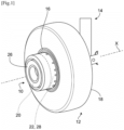
- FIG. 1 shows a device 10 for driving at least one wheel 12 of an aircraft landing gear 14.
- the device 10 comprises an electric motor 20 and a mechanical transmission system 22 between a shaft of the motor 20 and the rim 16 of the wheel 12.
- the motor 20 and the system 22 each have a generally annular shape and are centered on the X axis. They are arranged next to from each other and the system 22 is installed between the motor 20 and the rim 16. A part of the system 22, or even also a part of the motor 20, could be housed in the rim 16 to reduce the size of the device 10.
- the motor 20 and the system 22 can be protected by an external cylindrical cover 26 projecting on one side of the rim 16 or the tire 18.
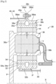
- the mechanical transmission system 22 comprises a mechanical speed reducer 28, examples of which are illustrated in figures 2 And 3 .
- the helix widths vary between the sun gear 32, the satellites 34 and the crown 38 because of the tooth overlaps, they are all centered on a median plane P for the upstream teeth and on another median plane P' for the downstream teeth.
- FIG. 2 thus illustrates the case of a single-stage gear reducer, i.e. the same toothing 34a of each satellite 34 cooperates with both the sun gear 32 and the crown wheel 38. Even if the toothing 34a comprises two sets of teeth, these teeth have the same average diameter and form a single set of teeth called a chevron.
- each satellite 34 comprises two separate teeth 34a1, 34a2 configured to cooperate respectively with the crown 38 and the sun gear 32.
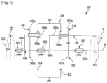
- FIG. 4 shows a first embodiment of a mechanical speed reducer 28 according to the invention which has the particularity of having a double epicyclic gear train.
- the solar 32 comprises a shaft 32c which can be that of the motor 20 or which can be connected to the shaft of the motor 20, and a pinion comprising at its external periphery the external toothing 32a.
- the reducer 28 is here of the double-stage type, that is to say that the first and second satellites 34, 46 are each here of the double-stage type and comprise two independent toothings 34a, 34b, 46a, 46b.
- the first planet carrier 36 comprises or carries physical axes 36b for supporting or even guiding the first satellites 34.
- the first planet carrier 36 further comprises a shaft 36c or a portion of shaft connected to a pinion comprising at its external periphery the external toothing 36a.
- the internal teeth 52, 54 are carried by the same crown 38. Alternatively, they could be carried by different crowns.
- the crown 38 is fixed and is therefore intended to be fixed to a stator of the device 10.
- the shafts 32c, 36c, 46c are centered and guided in rotation around the X axis by bearings 50.
- the teeth 34a, 34b, 32a are of any type and for example herringbone.
- the teeth 46a, 46b, 36a are of any type and preferably herringbone.
- the teeth 52, 54 are preferably helical.
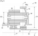
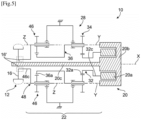
- FIG. 5 shows a device 10 for driving a wheel 12 of an aircraft landing gear, comprising the reducer 28 of the Figure 4 .
- the motor 20 of the device 10 comprises a rotor 20a and a stator 20b.
- the rotor 20a here has an annular shape and is connected to the shaft 32c.
- the stator 20b has an annular shape and extends around the rotor 20a and also on a side of the rotor 20a opposite the reduction gear 28.
- FIG. 6 shows an alternative embodiment of a device 10 for driving a wheel 12 of an aircraft landing gear according to the invention.
- teeth 32a and 34a are located in the same plane P1 perpendicular to the X axis.
- the teeth 34b and 52 are located in the same plane P2 perpendicular to the X axis.
- the teeth 46a and 36b are located in the same plane P3 perpendicular to the X axis.
- the teeth 46b and 54 are located in the same plane P4 perpendicular to the X axis.
- the crown 38 is arranged between the planes P1 and P3.
- the crown 38 has an external diameter D5 which defines the external diameter of the reducer 28 and which is preferably less than the external diameter D6 of the rim 16 so as to be able to axially house a part of the reducer 28 in the rim 16.
- FIGS. 7a and 7b show another alternative embodiment of a device 10 for driving a wheel 12 of an aircraft landing gear according to the invention.
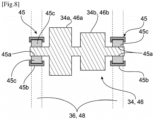
- FIG 8 shows an example of guidance of the satellites 34, 46 of the reducer 28.
- the satellites 34, 46 are guided by rolling bearings 45 which are here more particularly roller bearings.
- the guide bearings 45 of each satellite 34, 46 are two in number and are mounted around the longitudinal ends of this satellite, between these ends and the planet carrier 36, 48.
- Each of the bearings 45 comprises an internal ring 45a carried by the satellite 34, 46 or integrated into the latter, and an external ring 45b carried by the planet carrier 34, 48.
- the rollers 45c are mounted between the rings 45a, 45b.
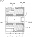
- the satellites 34, 46 are guided by needle bearings 47. These bearings 47 are two in number and are mounted radially inside the satellites 34, 46. Each of the bearings 47 is aligned radially with one of the teeth 34a, 46a of the satellite 34, 46. This assembly makes it possible to reduce the axial size.
- Each of the bearings 47 may have an axial length or dimension L1, L2 measured along the Y or Z axis, which represents at least 80% of the axial length or dimension L3, L4 of the corresponding toothing 34a, 46a.
- the guide bearings of the satellites 34, 46 are plain bearings or hydrodynamic bearings.
Landscapes
- Engineering & Computer Science (AREA)
- Mechanical Engineering (AREA)
- General Engineering & Computer Science (AREA)
- Aviation & Aerospace Engineering (AREA)
- Chemical & Material Sciences (AREA)
- Combustion & Propulsion (AREA)
- Transportation (AREA)
- Retarders (AREA)
Claims (8)
- Mechanisches Untersetzungsgetriebe (28) für eine Antriebsvorrichtung (10) für mindestens ein Rad (12) eines Luftfahrzeugfahrwerks (14), wobei dieses Untersetzungsgetriebe umfasst:- ein erstes Sonnenrad (32), das um eine X-Achse drehbeweglich ist und eine Außenverzahnung (32a) umfasst,- erste Planetenräder (34), die um die X-Achse verteilt sind und mit der Außenverzahnung (32a) des ersten Sonnenrads (32) kämmen, wobei diese ersten Planetenräder (34) um zur X-Achse parallele Y-Achsen drehbeweglich sind und von einem ersten Planetenradträger (36), der um die X-Achse drehbeweglich ist, getragen werden,- eine feste Krone (38), das mit den Planetenrädern (34) kämmt,- zweite Planetenräder (46), die um die X-Achse verteilt sind und mit der Krone (38) und mit einer Außenverzahnung (36a) des ersten Planetenradträgers (36) kämmen, wobei diese zweiten Planetenräder (46) um zur X-Achse parallele Z-Achsen drehbeweglich sind und von einem zweiten Planetenradträger (48), der um die X-Achse drehbeweglich ist, getragen werden, wobei- die ersten Planetenräder (34) jeweils eine erste Außenverzahnung (34a) umfassen, die mit der Außenverzahnung (32a) des ersten Sonnenrads (32) kämmt, und die zweiten Planetenräder (46) jeweils eine erste Außenverzahnung (46a) umfassen, die mit der Außenverzahnung (36a) des ersten Planetenradträgers (36) kämmt, dadurch gekennzeichnet, dass die ersten Planetenräder (34) auch eine zweite Außenverzahnung (34b) umfassen, die mit einer ersten Innenverzahnung (52) der Krone (38) kämmt, wobei die erste und die zweite Verzahnung (34a, 34b) jedes der ersten Planetenräder (34) unterschiedliche Durchmesser und/oder unterschiedliche Zähnezahlen aufweisen, und dadurch, dass die zweiten Planetenräder (46) auch eine zweite Außenverzahnung (46a) umfassen, die mit einer zweiten Innenverzahnung (54) der Krone (38) kämmt, wobei die erste und die zweite Verzahnung (46a, 46b) jedes der zweiten Planetenräder (34, 46) unterschiedliche Durchmesser und/oder unterschiedliche Zähnezahlen aufweisen.
- Untersetzungsgetriebe (28) nach Anspruch 1, wobei die Y-Achsen auf einem ersten Umfang (C1) liegen und die Z-Achsen auf einem zweiten Umfang (C2) liegen, wobei der erste und der zweite Umfang (C1, C2) unterschiedliche Durchmesser (D1, D2) aufweisen.
- Untersetzungsgetriebe (28) nach Anspruch 1, wobei die Y-Achsen auf einem ersten Umfang (C1) liegen und die Z-Achsen auf einem zweiten Umfang (C2) liegen, wobei der erste und der zweite Umfang (C1, C2) identische Durchmesser (D1, D2) aufweisen.
- Untersetzungsgetriebe (28) nach einem der vorstehenden Ansprüche, wobei die Anzahl von ersten Planetenrädern (34) gleich der Anzahl von zweiten Planetenrädern (46) ist.
- Untersetzungsgetriebe (28) nach einem der Ansprüche 1 bis 3, wobei sich die Anzahl von ersten Planetenrädern (34) von der Anzahl von zweiten Planetenrädern (46) unterscheidet.
- Untersetzungsgetriebe (28) nach einem der vorstehenden Ansprüche, wobei die Verzahnungen (34a, 34b, 46a, 46b) der ersten und der zweiten Planetenräder (34, 46) Pfeilverzahnungen sind und die Verzahnungen (52, 54) der Krone (38) Schrägverzahnungen sind.
- Untersetzungsgetriebe (28) nach einem der vorstehenden Ansprüche, wobei die ersten und die zweiten Planetenräder (34, 46) von Lagern (45, 47) drehgeführt werden, die an den Längsenden der Planetenräder (34, 46) oder radial innerhalb der Verzahnungen (34a, 34b, 46a, 46b) dieser Planetenräder liegen.
- Vorrichtung (10) zum Antrieb mindestens eines Rades (12) eines Luftfahrzeugfahrwerks, wobei diese Vorrichtung umfasst:- mindestens ein Rad (12) des Fahrwerks, wobei dieses Rad (12) eine Felge (16), die eine Drehachse (X) aufweist, umfasst,- einen Elektromotor (20), der eine Welle umfasst,- ein mechanisches Kraftübertragungssystem (22) zwischen der Welle des Motors (20) und der Felge (16), wobei dieses mechanische Kraftübertragungssystem (22) ein mechanisches Untersetzungsgetriebe (28) nach einem der vorstehenden Ansprüche umfasst.
Applications Claiming Priority (1)
| Application Number | Priority Date | Filing Date | Title |
|---|---|---|---|
| FR2209339A FR3139797B1 (fr) | 2022-09-16 | 2022-09-16 | Reducteur de vitesse pour un dispositif d’entrainement d’une roue d’un train d’atterrissage d’aeronef |
Publications (2)
| Publication Number | Publication Date |
|---|---|
| EP4339099A1 EP4339099A1 (de) | 2024-03-20 |
| EP4339099B1 true EP4339099B1 (de) | 2025-06-25 |
Family
ID=84331048
Family Applications (1)
| Application Number | Title | Priority Date | Filing Date |
|---|---|---|---|
| EP23196315.8A Active EP4339099B1 (de) | 2022-09-16 | 2023-09-08 | Untersetzungsgetriebe für eine antriebsvorrichtung eines rades eines flugzeugfahrwerks |
Country Status (3)
| Country | Link |
|---|---|
| US (1) | US12391373B2 (de) |
| EP (1) | EP4339099B1 (de) |
| FR (1) | FR3139797B1 (de) |
Families Citing this family (1)
| Publication number | Priority date | Publication date | Assignee | Title |
|---|---|---|---|---|
| FR3161413B1 (fr) | 2024-04-23 | 2026-04-03 | Safran Trans Systems | Dispositif d’entrainement d’au moins une roue d’un train d’atterrissage d’aeronef |
Family Cites Families (10)
| Publication number | Priority date | Publication date | Assignee | Title |
|---|---|---|---|---|
| GB1290501A (de) * | 1969-10-13 | 1972-09-27 | ||
| US6966865B2 (en) * | 2003-11-10 | 2005-11-22 | The Boeing Company | High ratio, reduced size epicyclic gear transmission for rotary wing aircraft with improved safety and noise reduction |
| FR3022858B1 (fr) | 2014-06-30 | 2018-01-05 | Compagnie Generale Des Etablissements Michelin | Systeme de motorisation de roue, notamment d'un aeronef |
| EP3193040A1 (de) * | 2016-01-12 | 2017-07-19 | Goodrich Actuation Systems SAS | Planetengetriebeanordnung |
| GB2562246B (en) * | 2017-05-09 | 2019-09-25 | Rolls Royce Plc | A Geared gas turbine engine |
| US20190191575A1 (en) | 2017-12-14 | 2019-06-20 | Keisha Tawn Lavergne | Fire and water resistant ankle monitor |
| AU2019201928B2 (en) * | 2018-03-23 | 2020-10-22 | Wheeltug plc | Epicyclic gearbox |
| EP3599391A1 (de) * | 2018-07-23 | 2020-01-29 | Flender GmbH | Koppelgetriebe für windkraftanlagen und industrie-applikationen |
| DE102018222005A1 (de) * | 2018-12-18 | 2020-06-18 | Zf Friedrichshafen Ag | Radnabengetriebe für einen Einzelradantrieb eines Kraftfahrzeugs |
| FR3108308B1 (fr) | 2020-03-19 | 2024-01-19 | Safran Trans Systems | Dispositif d’entrainement d’au moins une roue d’un train d’atterrissage d’aeronef |
-
2022
- 2022-09-16 FR FR2209339A patent/FR3139797B1/fr active Active
-
2023
- 2023-09-08 EP EP23196315.8A patent/EP4339099B1/de active Active
- 2023-09-13 US US18/466,330 patent/US12391373B2/en active Active
Also Published As
| Publication number | Publication date |
|---|---|
| US12391373B2 (en) | 2025-08-19 |
| FR3139797A1 (fr) | 2024-03-22 |
| EP4339099A1 (de) | 2024-03-20 |
| US20240092479A1 (en) | 2024-03-21 |
| FR3139797B1 (fr) | 2024-10-25 |
Similar Documents
| Publication | Publication Date | Title |
|---|---|---|
| EP3922886B1 (de) | Mechanisches reduktionsgetriebe für turbotriebwerk eines luftfahrzeugs | |
| EP3726031B1 (de) | Mechanisches reduktionsgetriebe für luftfahrzeug-turbotriebwerk | |
| EP4001619B1 (de) | Mechanisches getriebe einer luftfahrzeug-turbomaschine | |
| EP3922831B1 (de) | Mechanisches reduktionsgetriebe für turbotriebwerk eines luftfahrzeugs | |
| EP3995681B1 (de) | Mechanisches reduktionsgetriebe für turbotriebwerk eines luftfahrzeugs | |
| EP3992494B1 (de) | Mechanisches reduktionsgetriebe für turbotriebwerk eines luftfahrzeugs | |
| EP4303468B1 (de) | Sonnenrad für ein reduktionsgetriebe eines turbotriebwerks eines luftfahrzeugs | |
| EP4290097A1 (de) | Planetenträger für ein mechanisches reduktionsgetriebe eines turbotriebwerks eines luftfahrzeugs | |
| EP4382769B1 (de) | Krone für ein mechanisches reduktionsgetriebe eines flugzeugs | |
| EP4151846A1 (de) | Turbomaschine eines luftfahrzeugs | |
| EP4339099B1 (de) | Untersetzungsgetriebe für eine antriebsvorrichtung eines rades eines flugzeugfahrwerks | |
| EP4339097B1 (de) | Vorrichtung zum antrieb mindestens eines rades eines flugzeugfahrwerks | |
| EP4033086B1 (de) | Turbotriebwerk für luftfahrzeug mit dreifacher strömung, das mit einem leistungsübertragungsmodul ausgestattet ist | |
| EP4339098B1 (de) | Antriebsvorrichtung für mindestens ein rad eines flugzeugfahrwerks | |
| EP4689448A1 (de) | Bewegliches ringgetriebe für ein mechanisches untersetzungsgetriebe eines flugzeugs | |
| WO2025109268A1 (fr) | Dispositif d'entrainement d'au moins une roue d'un train d'atterrissage d'aeronef | |
| FR3161413A1 (fr) | Dispositif d’entrainement d’au moins une roue d’un train d’atterrissage d’aeronef | |
| EP4242489B1 (de) | Mechanisches reduktionsgetriebe für flugzeugturbomaschine | |
| EP4339484A1 (de) | Flugzeugturbomaschine mit mechanischem untersetzungsgetriebe | |
| EP4689447A1 (de) | Anordnung für ein mechanisches reduktionsgetriebe eines flugzeugs | |
| WO2024209160A1 (fr) | Carter fixe pour un reducteur mecanique d'aeronef | |
| EP4471295A1 (de) | Solar für ein mechanisches reduktionsgetriebe eines turbotriebwerks eines luftfahrzeugs | |
| WO2024261427A1 (fr) | Turbomachine d'aeronef a double helice de propulsion | |
| WO2025109264A1 (fr) | Motoreducteur pour un aeronef |
Legal Events
| Date | Code | Title | Description |
|---|---|---|---|
| PUAI | Public reference made under article 153(3) epc to a published international application that has entered the european phase |
Free format text: ORIGINAL CODE: 0009012 |
|
| STAA | Information on the status of an ep patent application or granted ep patent |
Free format text: STATUS: REQUEST FOR EXAMINATION WAS MADE |
|
| 17P | Request for examination filed |
Effective date: 20230908 |
|
| AK | Designated contracting states |
Kind code of ref document: A1 Designated state(s): AL AT BE BG CH CY CZ DE DK EE ES FI FR GB GR HR HU IE IS IT LI LT LU LV MC ME MK MT NL NO PL PT RO RS SE SI SK SM TR |
|
| GRAP | Despatch of communication of intention to grant a patent |
Free format text: ORIGINAL CODE: EPIDOSNIGR1 |
|
| STAA | Information on the status of an ep patent application or granted ep patent |
Free format text: STATUS: GRANT OF PATENT IS INTENDED |
|
| RIC1 | Information provided on ipc code assigned before grant |
Ipc: F16H 1/28 20060101ALI20250128BHEP Ipc: B64C 25/40 20060101AFI20250128BHEP |
|
| INTG | Intention to grant announced |
Effective date: 20250217 |
|
| GRAS | Grant fee paid |
Free format text: ORIGINAL CODE: EPIDOSNIGR3 |
|
| GRAA | (expected) grant |
Free format text: ORIGINAL CODE: 0009210 |
|
| STAA | Information on the status of an ep patent application or granted ep patent |
Free format text: STATUS: THE PATENT HAS BEEN GRANTED |
|
| AK | Designated contracting states |
Kind code of ref document: B1 Designated state(s): AL AT BE BG CH CY CZ DE DK EE ES FI FR GB GR HR HU IE IS IT LI LT LU LV MC ME MK MT NL NO PL PT RO RS SE SI SK SM TR |
|
| REG | Reference to a national code |
Ref country code: GB Ref legal event code: FG4D Free format text: NOT ENGLISH |
|
| REG | Reference to a national code |
Ref country code: CH Ref legal event code: EP |
|
| REG | Reference to a national code |
Ref country code: CH Ref legal event code: EP |
|
| REG | Reference to a national code |
Ref country code: IE Ref legal event code: FG4D Free format text: LANGUAGE OF EP DOCUMENT: FRENCH |
|
| REG | Reference to a national code |
Ref country code: DE Ref legal event code: R096 Ref document number: 602023004267 Country of ref document: DE |
|
| PG25 | Lapsed in a contracting state [announced via postgrant information from national office to epo] |
Ref country code: FI Free format text: LAPSE BECAUSE OF FAILURE TO SUBMIT A TRANSLATION OF THE DESCRIPTION OR TO PAY THE FEE WITHIN THE PRESCRIBED TIME-LIMIT Effective date: 20250625 |
|
| PGFP | Annual fee paid to national office [announced via postgrant information from national office to epo] |
Ref country code: DE Payment date: 20250919 Year of fee payment: 3 |
|
| REG | Reference to a national code |
Ref country code: LT Ref legal event code: MG9D |
|
| PG25 | Lapsed in a contracting state [announced via postgrant information from national office to epo] |
Ref country code: GR Free format text: LAPSE BECAUSE OF FAILURE TO SUBMIT A TRANSLATION OF THE DESCRIPTION OR TO PAY THE FEE WITHIN THE PRESCRIBED TIME-LIMIT Effective date: 20250926 Ref country code: NO Free format text: LAPSE BECAUSE OF FAILURE TO SUBMIT A TRANSLATION OF THE DESCRIPTION OR TO PAY THE FEE WITHIN THE PRESCRIBED TIME-LIMIT Effective date: 20250925 |
|
| PG25 | Lapsed in a contracting state [announced via postgrant information from national office to epo] |
Ref country code: BG Free format text: LAPSE BECAUSE OF FAILURE TO SUBMIT A TRANSLATION OF THE DESCRIPTION OR TO PAY THE FEE WITHIN THE PRESCRIBED TIME-LIMIT Effective date: 20250625 |
|
| PG25 | Lapsed in a contracting state [announced via postgrant information from national office to epo] |
Ref country code: HR Free format text: LAPSE BECAUSE OF FAILURE TO SUBMIT A TRANSLATION OF THE DESCRIPTION OR TO PAY THE FEE WITHIN THE PRESCRIBED TIME-LIMIT Effective date: 20250625 |
|
| PGFP | Annual fee paid to national office [announced via postgrant information from national office to epo] |
Ref country code: FR Payment date: 20250923 Year of fee payment: 3 Ref country code: AT Payment date: 20251020 Year of fee payment: 3 |
|
| PG25 | Lapsed in a contracting state [announced via postgrant information from national office to epo] |
Ref country code: RS Free format text: LAPSE BECAUSE OF FAILURE TO SUBMIT A TRANSLATION OF THE DESCRIPTION OR TO PAY THE FEE WITHIN THE PRESCRIBED TIME-LIMIT Effective date: 20250925 |
|
| PG25 | Lapsed in a contracting state [announced via postgrant information from national office to epo] |
Ref country code: LV Free format text: LAPSE BECAUSE OF FAILURE TO SUBMIT A TRANSLATION OF THE DESCRIPTION OR TO PAY THE FEE WITHIN THE PRESCRIBED TIME-LIMIT Effective date: 20250625 |
|
| REG | Reference to a national code |
Ref country code: NL Ref legal event code: MP Effective date: 20250625 |
|
| PG25 | Lapsed in a contracting state [announced via postgrant information from national office to epo] |
Ref country code: NL Free format text: LAPSE BECAUSE OF FAILURE TO SUBMIT A TRANSLATION OF THE DESCRIPTION OR TO PAY THE FEE WITHIN THE PRESCRIBED TIME-LIMIT Effective date: 20250625 |
|
| PG25 | Lapsed in a contracting state [announced via postgrant information from national office to epo] |
Ref country code: PT Free format text: LAPSE BECAUSE OF FAILURE TO SUBMIT A TRANSLATION OF THE DESCRIPTION OR TO PAY THE FEE WITHIN THE PRESCRIBED TIME-LIMIT Effective date: 20251027 |
|
| REG | Reference to a national code |
Ref country code: AT Ref legal event code: MK05 Ref document number: 1806239 Country of ref document: AT Kind code of ref document: T Effective date: 20250625 |
|
| PG25 | Lapsed in a contracting state [announced via postgrant information from national office to epo] |
Ref country code: IS Free format text: LAPSE BECAUSE OF FAILURE TO SUBMIT A TRANSLATION OF THE DESCRIPTION OR TO PAY THE FEE WITHIN THE PRESCRIBED TIME-LIMIT Effective date: 20251025 |
|
| PG25 | Lapsed in a contracting state [announced via postgrant information from national office to epo] |
Ref country code: SM Free format text: LAPSE BECAUSE OF FAILURE TO SUBMIT A TRANSLATION OF THE DESCRIPTION OR TO PAY THE FEE WITHIN THE PRESCRIBED TIME-LIMIT Effective date: 20250625 Ref country code: AT Free format text: LAPSE BECAUSE OF FAILURE TO SUBMIT A TRANSLATION OF THE DESCRIPTION OR TO PAY THE FEE WITHIN THE PRESCRIBED TIME-LIMIT Effective date: 20250625 |
|
| PG25 | Lapsed in a contracting state [announced via postgrant information from national office to epo] |
Ref country code: CZ Free format text: LAPSE BECAUSE OF FAILURE TO SUBMIT A TRANSLATION OF THE DESCRIPTION OR TO PAY THE FEE WITHIN THE PRESCRIBED TIME-LIMIT Effective date: 20250625 |
|
| PG25 | Lapsed in a contracting state [announced via postgrant information from national office to epo] |
Ref country code: PL Free format text: LAPSE BECAUSE OF FAILURE TO SUBMIT A TRANSLATION OF THE DESCRIPTION OR TO PAY THE FEE WITHIN THE PRESCRIBED TIME-LIMIT Effective date: 20250625 |
|
| PG25 | Lapsed in a contracting state [announced via postgrant information from national office to epo] |
Ref country code: EE Free format text: LAPSE BECAUSE OF FAILURE TO SUBMIT A TRANSLATION OF THE DESCRIPTION OR TO PAY THE FEE WITHIN THE PRESCRIBED TIME-LIMIT Effective date: 20250625 |
|
| PG25 | Lapsed in a contracting state [announced via postgrant information from national office to epo] |
Ref country code: SK Free format text: LAPSE BECAUSE OF FAILURE TO SUBMIT A TRANSLATION OF THE DESCRIPTION OR TO PAY THE FEE WITHIN THE PRESCRIBED TIME-LIMIT Effective date: 20250625 |
|
| PG25 | Lapsed in a contracting state [announced via postgrant information from national office to epo] |
Ref country code: ES Free format text: LAPSE BECAUSE OF FAILURE TO SUBMIT A TRANSLATION OF THE DESCRIPTION OR TO PAY THE FEE WITHIN THE PRESCRIBED TIME-LIMIT Effective date: 20250625 |
|
| PG25 | Lapsed in a contracting state [announced via postgrant information from national office to epo] |
Ref country code: RO Free format text: LAPSE BECAUSE OF FAILURE TO SUBMIT A TRANSLATION OF THE DESCRIPTION OR TO PAY THE FEE WITHIN THE PRESCRIBED TIME-LIMIT Effective date: 20250625 |
|
| PG25 | Lapsed in a contracting state [announced via postgrant information from national office to epo] |
Ref country code: DK Free format text: LAPSE BECAUSE OF FAILURE TO SUBMIT A TRANSLATION OF THE DESCRIPTION OR TO PAY THE FEE WITHIN THE PRESCRIBED TIME-LIMIT Effective date: 20250625 |
|
| PG25 | Lapsed in a contracting state [announced via postgrant information from national office to epo] |
Ref country code: IT Free format text: LAPSE BECAUSE OF FAILURE TO SUBMIT A TRANSLATION OF THE DESCRIPTION OR TO PAY THE FEE WITHIN THE PRESCRIBED TIME-LIMIT Effective date: 20250625 |
|
| PLBE | No opposition filed within time limit |
Free format text: ORIGINAL CODE: 0009261 |
|
| STAA | Information on the status of an ep patent application or granted ep patent |
Free format text: STATUS: NO OPPOSITION FILED WITHIN TIME LIMIT |