EP4339074A1 - Motor vehicle provided with a reinforcing structure - Google Patents
Motor vehicle provided with a reinforcing structure Download PDFInfo
- Publication number
- EP4339074A1 EP4339074A1 EP23196224.2A EP23196224A EP4339074A1 EP 4339074 A1 EP4339074 A1 EP 4339074A1 EP 23196224 A EP23196224 A EP 23196224A EP 4339074 A1 EP4339074 A1 EP 4339074A1
- Authority
- EP
- European Patent Office
- Prior art keywords
- motor vehicle
- frame
- reinforcing structure
- subframe
- respect
- Prior art date
- Legal status (The legal status is an assumption and is not a legal conclusion. Google has not performed a legal analysis and makes no representation as to the accuracy of the status listed.)
- Pending
Links
- 230000003014 reinforcing effect Effects 0.000 title claims abstract description 42
- 239000000725 suspension Substances 0.000 claims abstract description 13
- 239000012212 insulator Substances 0.000 claims abstract description 9
- 230000003247 decreasing effect Effects 0.000 claims description 2
- 238000005096 rolling process Methods 0.000 description 5
- 230000008878 coupling Effects 0.000 description 3
- 238000010168 coupling process Methods 0.000 description 3
- 238000005859 coupling reaction Methods 0.000 description 3
- 241000826860 Trapezium Species 0.000 description 1
- 230000005540 biological transmission Effects 0.000 description 1
- 238000002485 combustion reaction Methods 0.000 description 1
- 238000013016 damping Methods 0.000 description 1
- 230000001419 dependent effect Effects 0.000 description 1
- 230000005484 gravity Effects 0.000 description 1
- 230000000670 limiting effect Effects 0.000 description 1
- 239000002184 metal Substances 0.000 description 1
- 230000004048 modification Effects 0.000 description 1
- 238000012986 modification Methods 0.000 description 1
- 230000036961 partial effect Effects 0.000 description 1
- 230000001681 protective effect Effects 0.000 description 1
- 230000002787 reinforcement Effects 0.000 description 1
- 125000006850 spacer group Chemical group 0.000 description 1
- 230000003068 static effect Effects 0.000 description 1
Images



Classifications
-
- B—PERFORMING OPERATIONS; TRANSPORTING
- B62—LAND VEHICLES FOR TRAVELLING OTHERWISE THAN ON RAILS
- B62D—MOTOR VEHICLES; TRAILERS
- B62D21/00—Understructures, i.e. chassis frame on which a vehicle body may be mounted
- B62D21/11—Understructures, i.e. chassis frame on which a vehicle body may be mounted with resilient means for suspension, e.g. of wheels or engine; sub-frames for mounting engine or suspensions
-
- B—PERFORMING OPERATIONS; TRANSPORTING
- B62—LAND VEHICLES FOR TRAVELLING OTHERWISE THAN ON RAILS
- B62D—MOTOR VEHICLES; TRAILERS
- B62D21/00—Understructures, i.e. chassis frame on which a vehicle body may be mounted
- B62D21/09—Means for mounting load bearing surfaces
-
- B—PERFORMING OPERATIONS; TRANSPORTING
- B62—LAND VEHICLES FOR TRAVELLING OTHERWISE THAN ON RAILS
- B62D—MOTOR VEHICLES; TRAILERS
- B62D21/00—Understructures, i.e. chassis frame on which a vehicle body may be mounted
- B62D21/02—Understructures, i.e. chassis frame on which a vehicle body may be mounted comprising longitudinally or transversely arranged frame members
-
- B—PERFORMING OPERATIONS; TRANSPORTING
- B62—LAND VEHICLES FOR TRAVELLING OTHERWISE THAN ON RAILS
- B62D—MOTOR VEHICLES; TRAILERS
- B62D27/00—Connections between superstructure or understructure sub-units
- B62D27/04—Connections between superstructure or understructure sub-units resilient
-
- B—PERFORMING OPERATIONS; TRANSPORTING
- B62—LAND VEHICLES FOR TRAVELLING OTHERWISE THAN ON RAILS
- B62D—MOTOR VEHICLES; TRAILERS
- B62D27/00—Connections between superstructure or understructure sub-units
- B62D27/06—Connections between superstructure or understructure sub-units readily releasable
- B62D27/065—Connections between superstructure or understructure sub-units readily releasable using screwthread
Definitions
- the present invention concerns a motor vehicle provided with a reinforcing structure.
- the frame of a motor vehicle is the supporting structure to which all the components of the motor vehicle are directly or indirectly fixed. More specifically, the engine, which can be an internal combustion engine or an electric motor, and the suspensions, which support the wheels, are fixed to the frame.
- the vibrations that are generated by rolling of the wheels on the road surface are transmitted to the rear subframe (to which the rear suspensions are directly constrained) but are not transmitted (or only minimally transmitted) by the rear subframe to the frame thanks to interposition of the elastic insulator elements.
- the geometry of the frame must be such as to guarantee sufficient space for the shaking of the subframe.
- said portion is concave in the shape of a "C" in a lateral view of the vehicle.
- said conformation of the frame significantly affects structural efficiency in terms of static, torsional and flexional rigidities, and frequency response of the structure.
- An object of the invention is to respond to the above need, preferably in a simple reliable manner.
- the number 1 indicates overall a motor vehicle comprising a frame 2 and a plurality of wheels - not illustrated - rotatable relative to the frame 2 around respective rotation axes and adapted to move the frame 2 relative to the ground.
- the motor vehicle 1 defines an integral reference system originating in the centre of gravity of the motor vehicle 1 and comprising ( figure 1 ):
- the motor vehicle 1 furthermore defines a front portion 1a and a rear portion 1b, which are opposite to each other along the longitudinal axis X.
- the adjectives "front” and “rear” shall be understood relative to an advancement direction V of the motor vehicle 1 oriented from the rear portion 1b towards the front portion 1a ( figure 1 ) .
- the motor vehicle 1 comprises two front wheels arranged at the front portion 1a and two rear wheels arranged at the portion 1b.
- the motor vehicle 1 further comprises:
- the frame 2 comprises:
- the rear body 5 comprises, in turn, a concave portion 6 adapted to be facing the ground on which the wheels of the motor vehicle 1 rest and at which the subframe 10 is at least partially housed.
- the concave portion 6 has a C-shaped cross section in a plane passing through the axes X and Z ( figure 1 ).
- the subframe 10 is fixed to the rear body 5 of the frame 2 at a plurality of fixing points 12a, 12b. In the embodiment illustrated, there are four fixing points 12a, 12b ( figure 1 ).
- the subframe 10 comprises a through hole 13 at each of the fixing points 12a, 12b and the elastic insulator elements 11 comprise elastic bushings 110 each housed at a respective hole 13 ( figure 4 ).
- Each elastic bushing 110 in turn comprises:
- the cylindrical portions 111 and 112 are arranged coaxially to each other. Furthermore, the axis of the elastic bushings 110 is arranged parallel to the axis Z ( figure 4 ).
- the subframe 10 comprises two front fixing points 12a arranged on the side of the front portion 1a and two rear fixing points 12b arranged on the side of the rear portion 1b.
- a median plane M of the subframe 10 along the axis Y directed parallel to the longitudinal axis X, which divides the subframe 10 into two halves 10a and 10b.
- Each of the two halves 10a, 10b comprises a front fixing point 12a and a rear fixing point 12b spaced from each other with respect to the longitudinal axis X ( figure 2 ).
- the front fixing point 12a and the rear fixing point 12b of one of the two halves 10a, 10b are arranged symmetrically to the front fixing point 12a and to the rear fixing point 12b of the other of the two halves 10b, 10a with respect to the median plane M.
- the front fixing points 12a are aligned with each another along a direction I parallel to the axis Y.
- the rear fixing points 12b are aligned with each another in a direction J parallel to the axis Y and to the direction I ( figure 2 ).
- the front fixing point 12a and the rear fixing point 12b of each of the two halves 10a, 10b are aligned with each other in respective directions K, L transverse to the longitudinal axis X and incident to each other.
- the fixing points 12a and 12b are arranged at respective vertexes of an isosceles trapezium.
- the front fixing points 12a are arranged at a same first coordinate relative to the axis Z and the rear fixing points 12b are arranged at a same second coordinate relative to the axis Z.
- the front fixing points 12a are arranged below the rear fixing points 12b.
- the front fixing points 12a are adapted to be closer to the ground than the rear fixing points 12b.
- the subframe 10 further comprises ( figure 2 ):
- the body 20 is arranged on the side of the half 10a and the body 21 is arranged on the side of the half 10b.
- the cross members 22 and 23 are spaced from each other along the longitudinal axis X and extend parallel to each other and to the axis Y.
- the cross member 23 extends in the direction J and joins the rear fixing points 12b.
- the cross member 22 is spaced from the front fixing points 12a along the longitudinal axis X towards the rear fixing points 12b.
- the cross sections of the cross members 22 and 23 have a rectangular shape.
- the cross members 22 and 23 are aligned or substantially aligned with each other with respect to the axis Z.
- the upper surfaces - namely the surfaces that are opposite the ground - of the cross members 22 and 23 are coplanar or substantially coplanar.
- the body 20 comprises, in turn:
- the portion 20a extends parallel or substantially parallel to the longitudinal axis X, while the arm 20b is directed crosswise to the longitudinal axis X.
- the body 21 comprises:
- the portion 21a extends parallel or substantially parallel to the longitudinal axis X, while the arm 21b is directed crosswise to the longitudinal axis X.
- the portions 20a and 21a comprise, in turn, respective openings 25, 26 arranged symmetrically or substantially symmetrically to each other with respect to the median plane M. Specifically, the openings 25 and 26 are crossed by the axle shafts of the rear wheels, not illustrated.
- the subframe 10 also comprises a cross member 24, which joins the bodies 20 and 21 to each other and extends crosswise thereto.
- the cross member 24 is furthermore arranged above the cross members 22 and 23, namely it is more spaced from the ground on which the wheels rest than the cross members 22 and 23.
- the cross member 24 extends parallel to the Y axis and to the cross members 22 and 23. Furthermore, the cross member 24 joins the upper vertexes of the triangular shapes of the portions 20a and 21a.
- the subframe 10 comprises a plurality of coupling elements 30 ( figures 2 and 3 ) configured to allow the coupling of one or more rear suspensions, namely the suspensions that indirectly connect the rear wheels to the frame 2.
- the levers of said rear suspensions are connected only to the subframe 10 and do not have any direct connection to the rear body 5 of the frame 2.
- the coupling elements 30 are arranged at the portions 20a and 21a ( figure 2 ).
- the motor vehicle 1 comprises a reinforcing structure 15 directly fixed to the frame 2; the subframe 10 is operatively interposed between the frame 2 and the reinforcing structure 15 and in contact with the frame 2 and the reinforcing structure 15, in particular parallel to the axis Z ( figure 1 ).
- the subframe 10 is compressed and/or sandwiched for at least part of the extension thereof between frame 2 and reinforcing structure 15.
- reinforcing structure 15 is directly attached to frame 2, it is meant that reinforcing structure 15 is attached to frame 2 independently of subframe 10.
- the motor vehicle 1 further comprises connecting elements 50 adapted to fix the reinforcing structure 15 to the frame 2 and which will be described in detail in the following part of the present description.
- the frame 2 comprises a plurality of holes 51, which are specifically threaded holes, adapted to be each engaged by a respective connecting element 50.
- the reinforcing structure 15 is directly fixed to the frame 2, at the rear body 5.
- the reinforcing structure 15 comprises:
- the central plate 40, the front body 41 and/or the rear body 42 form a single piece.
- the central plate 40 is rectangular and comprises two sides 401, 402 extending parallel to the axis Y and two sides 403, 404 extending parallel to the axis X.
- the central plate 40 further comprises:
- the front body 41 is fixed to the central plate 40 at the side 401 and comprises two through holes 43, 44 for fixing the reinforcing structure 15 to the frame 2.
- the holes 43 and 44 are each aligned with a respective front fixing point 12a (namely with a respective hole 13 of the subframe 10) and with a respective hole 51 of the frame 2 parallel to the axis Z.
- the holes 43 and 44 are symmetrical to each other with respect to the median plane M and are aligned with each other in a direction parallel to the axis Y.
- the extension of the front body 41 parallel to the axis Y is greater than the extension of the central plate 40 along the axis Y.
- the front body 41 protrudes parallel to the axis Y with respect to the side 401, both on the side of the half 10a and on the side of the half 10b.
- the front body 41 comprises ( figure 3 ):
- the first and the second portion 41a, 41b are arranged in succession along the axis X.
- the second portion 41b has an extension progressively decreasing parallel to the axis Z.
- the holes 43 and 44 are arranged at the first portion 41a.
- the reinforcing structure 15 further comprises two angle elements 45, 46 adapted to fix the front body 41 to the central plate 40 and/or to stiffen the connection between the front body 41 and the central plate 40.
- each of the two angle elements 45, 46 is fixed both to the front body 41 and to a respective reinforcing element 40b, 40c.
- the angle elements 45, 46 are fixed at the respective portions of the front body 41 which protrude parallel to the axis Y with respect to the central plate 40.
- the reinforcing structure 15 is symmetrical with respect to the median plane M.
- the rear body 42 is fixed to the central plate 40 at the side 402 and comprises two through holes 47, 48 for fixing the reinforcing structure 15 to the frame 2.
- the holes 47 and 48 are each aligned with a respective rear fixing point 12b (namely with a respective hole 13 of the subframe 10) and with a respective hole 51 of the frame 2 parallel to the axis Z.
- the holes 47 and 48 are symmetrical to each other relative to the median plane M and are aligned with each other in a direction parallel to the axis Y. In addition, the axes of the holes 47 and 48 are arranged parallel to the axis Z.
- the extension of the rear body 42 parallel to the axis Y is greater than the extension of the central plate 40 parallel to the axis Y, but smaller than the extension of the front body 41 parallel to the axis Y.
- the rear body 42 protrudes parallel to the axis Y with respect to the side 402 both on the side of the half 10a and on the side of the half 10b.
- each connecting element 50 engages at the same time a respective hole 43, 44, 47, 48 of the reinforcing structure 15, a respective hole 13 of the subframe 10 and a respective hole 51 of the frame 2.
- each connecting element 50 engaging the respective hole 13 engages a respective elastic bushing 110 housed therein.
- each connecting element 50 comprises a screw 60 (only two of which are shown in figure 3 ) defining an axial end 60a arranged on the side of the frame 2 and an axial end 60b opposite the axial end 60a and arranged on the side of the reinforcing structure 15 ( figure 4 ).
- each screw 60 comprises along its longitudinal axis:
- Each connecting element 50 further comprises a nut 70 engaged with the screw 60 at the stretch 64.
- each screw 60 also comprises a shoulder 65 axially interposed between the stretch 62 and the stretch 63.
- each elastic bushing 110 is positioned in abutment against the shoulder 65 of the respective screw 60 on the side of said shoulder 65 facing the frame 2.
- each screw 60 also comprises a spacer 66 at the stretch 63, arranged concentrically and radially external to the stretch 63.
- connecting elements 50 are adapted to fix reinforcing structure 15 to frame 2 independently of subframe 10. In detail, connecting elements 50 would fix reinforcing structure 15 to frame 2 even in the absence of subframe 10.
- the wheels rotate around the respective rotation axes, determining the movement of the frame 2 with respect to the ground.
- vibrations are generated due to the irregularities of the road surface. Said vibrations are transmitted to the subframe 10 by means of the rear suspensions, but are not transmitted (or only minimally transmitted) from the subframe 10 to the frame 2 due to the interposition of the elastic insulator elements 11.
- the subframe 10 is interposed between the frame 2 and the reinforcing structure 15, which is in turn directly fixed to the frame 2.
- the vehicle 1 comprises the reinforcing structure 15, which is directly fixed to the frame 2, and since the subframe 10 is interposed between the frame 2 and the reinforcing structure 15, it is possible to damp the vibrations due to rolling on the road surface while maintaining a high structural efficiency of the frame 2. Specifically, the rigidity of the frame 2 is increased by the presence of the reinforcing structure 15.
- the reinforcing structure 15 limits the shaking thereof.
Landscapes
- Engineering & Computer Science (AREA)
- Chemical & Material Sciences (AREA)
- Combustion & Propulsion (AREA)
- Transportation (AREA)
- Mechanical Engineering (AREA)
- Body Structure For Vehicles (AREA)
Abstract
Description
- This patent application claims priority from
Italian patent application no. 102022000018501 filed on September 12, 2022 - The present invention concerns a motor vehicle provided with a reinforcing structure.
- The frame of a motor vehicle is the supporting structure to which all the components of the motor vehicle are directly or indirectly fixed. More specifically, the engine, which can be an internal combustion engine or an electric motor, and the suspensions, which support the wheels, are fixed to the frame.
- In order to increase the comfort of the passenger compartment occupants, transmission towards the frame of the vibrations generated by rolling of the wheels on the road surface must be minimized. For this reason, mounting of the rear suspensions on a rear subframe, which is fixed to the frame by the interposition of elastic insulator elements, for example rubber blocks, has been proposed. Said elastic insulator elements insulate the frame from the rear subframe in terms of vibrations.
- In other words, the vibrations that are generated by rolling of the wheels on the road surface are transmitted to the rear subframe (to which the rear suspensions are directly constrained) but are not transmitted (or only minimally transmitted) by the rear subframe to the frame thanks to interposition of the elastic insulator elements.
- This solution has proved to be very effective in reducing the level of vibrations transmitted to the frame and therefore perceived by the occupants of the passenger compartment.
- In order to allow housing of the subframe, the geometry of the frame must be such as to guarantee sufficient space for the shaking of the subframe. For example, said portion is concave in the shape of a "C" in a lateral view of the vehicle.
- However, said conformation of the frame significantly affects structural efficiency in terms of static, torsional and flexional rigidities, and frequency response of the structure.
- In the light of the above, the need is therefore felt to improve the known motor vehicles, in order to obtain damping of the vibrations due to rolling on the road surface, maintaining a high structural efficiency of the frame.
- An object of the invention is to respond to the above need, preferably in a simple reliable manner.
- The object is achieved by a motor vehicle as defined in claim 1.
- The dependent claims define particular embodiments of the invention.
- The present invention will now be described with reference to the attached drawings, which illustrate a non-limiting embodiment example thereof, in which:
-
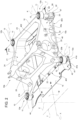
figure 1 is a schematic perspective view from below of a motor vehicle according to the present invention, with parts removed for clarity; -
figure 2 is a perspective view of two components of the motor vehicle illustrated infigure 1 ; -
figure 3 is an exploded view of the components illustrated infigure 2 ; and -
figure 4 is a partial section on an enlarged scale along the line IV-IV infigure 2 . - In
figure 1 , the number 1 indicates overall a motor vehicle comprising aframe 2 and a plurality of wheels - not illustrated - rotatable relative to theframe 2 around respective rotation axes and adapted to move theframe 2 relative to the ground. - The motor vehicle 1 defines an integral reference system originating in the centre of gravity of the motor vehicle 1 and comprising (
figure 1 ): - a longitudinal axis X;
- an axis Y orthogonal to the axis X; and
- an axis Z orthogonal to the axes X and Y and vertical, in use.
- The motor vehicle 1 furthermore defines a
front portion 1a and arear portion 1b, which are opposite to each other along the longitudinal axis X. In the following description, the adjectives "front" and "rear" shall be understood relative to an advancement direction V of the motor vehicle 1 oriented from therear portion 1b towards thefront portion 1a (figure 1 ) . - In greater detail, the motor vehicle 1 comprises two front wheels arranged at the
front portion 1a and two rear wheels arranged at theportion 1b. - The motor vehicle 1 further comprises:
- a plurality of suspensions - not illustrated - that support the wheels at variable relative distances from the
frame 2 along the axis Z; and - a
subframe 10, to which at least some of the suspensions are fixed and which is fixed to theframe 2 by the interposition ofelastic insulator elements 11. - As illustrated in
figure 1 , theframe 2 comprises: - a
central body 3, at which a passenger compartment of the motor vehicle 1 is defined; - a front body 4 arranged on the side of the
front portion 1a, which supports the front wheels; and - a
rear body 5 on the side of therear portion 1b, which supports the rear wheels. - The
rear body 5 comprises, in turn, aconcave portion 6 adapted to be facing the ground on which the wheels of the motor vehicle 1 rest and at which thesubframe 10 is at least partially housed. In the embodiment shown, theconcave portion 6 has a C-shaped cross section in a plane passing through the axes X and Z (figure 1 ). - The
subframe 10 is fixed to therear body 5 of theframe 2 at a plurality offixing points fixing points figure 1 ). - In detail, the
subframe 10 comprises a throughhole 13 at each of thefixing points elastic insulator elements 11 comprise elastic bushings 110 each housed at a respective hole 13 (figure 4 ). - Each elastic bushing 110 in turn comprises:
- a deformable
cylindrical portion 111, for example made of rubber, positioned in contact with the inner walls of therelative hole 13; and - a
cylindrical portion 112, preferably made of metal and arranged in a radially internal manner with respect to thecylindrical portion 111. - The
cylindrical portions figure 4 ). - In further detail, the
subframe 10 comprises twofront fixing points 12a arranged on the side of thefront portion 1a and tworear fixing points 12b arranged on the side of therear portion 1b. - It is also possible to define a median plane M of the
subframe 10 along the axis Y directed parallel to the longitudinal axis X, which divides thesubframe 10 into twohalves halves front fixing point 12a and arear fixing point 12b spaced from each other with respect to the longitudinal axis X (figure 2 ). - In detail, the
front fixing point 12a and therear fixing point 12b of one of the twohalves front fixing point 12a and to therear fixing point 12b of the other of the twohalves - In greater detail, the
front fixing points 12a are aligned with each another along a direction I parallel to the axis Y. Analogously, therear fixing points 12b are aligned with each another in a direction J parallel to the axis Y and to the direction I (figure 2 ). - The
front fixing point 12a and therear fixing point 12b of each of the twohalves - In other words, the
fixing points - Furthermore, the
front fixing points 12a are arranged at a same first coordinate relative to the axis Z and therear fixing points 12b are arranged at a same second coordinate relative to the axis Z. In particular, thefront fixing points 12a are arranged below therear fixing points 12b. In other words, thefront fixing points 12a are adapted to be closer to the ground than therear fixing points 12b. - The
subframe 10 further comprises (figure 2 ): - a
body 20, which joins afront fixing point 12a to the respectiverear fixing point 12b aligned with each other in the direction K; - a
body 21, which joins afront fixing point 12a to the respectiverear fixing point 12b aligned with each other in the direction L; and - two
cross members bodies - In particular, the
body 20 is arranged on the side of thehalf 10a and thebody 21 is arranged on the side of the half 10b. - The
cross members - In detail, the
cross member 23 extends in the direction J and joins the rear fixing points 12b. Thecross member 22 is spaced from thefront fixing points 12a along the longitudinal axis X towards the rear fixing points 12b. - In further detail, in a plane orthogonal to the axis Y, the cross sections of the
cross members - Preferably, furthermore, the
cross members cross members - The
body 20 comprises, in turn: - a
portion 20a, having triangular or substantially triangular shape in a plane orthogonal to axis Y, which extends between thecross member 22 and therear fixing point 12b arranged at thehalf 10a; and - an
arm 20b, which extends between thecross member 22 and thefront fixing point 12a arranged at thehalf 10a. - The
portion 20a extends parallel or substantially parallel to the longitudinal axis X, while thearm 20b is directed crosswise to the longitudinal axis X. - Analogously to the
body 20, thebody 21 comprises: - a
portion 21a, having triangular or substantially triangular shape in a plane orthogonal to axis Y, which extends between thecross member 22 and therear fixing point 12b arranged at the half 10b; and - an
arm 21b, which extends between thecross member 22 and thefront fixing point 12a arranged at the half 10b. - The
portion 21a extends parallel or substantially parallel to the longitudinal axis X, while thearm 21b is directed crosswise to the longitudinal axis X. - Proceeding along the longitudinal axis X in the direction oriented from
rear portion 1b tofront portion 1a, the distance between corresponding points ofarm 20b andarm 21b parallel to axis Y progressively increases. In other words, proceeding along the longitudinal axis X in the direction oriented fromrear portion 1b tofront portion 1a,arms cross member 22. - The
portions respective openings openings - In the embodiment illustrated, the
subframe 10 also comprises across member 24, which joins thebodies cross member 24 is furthermore arranged above thecross members cross members - The
cross member 24 extends parallel to the Y axis and to thecross members cross member 24 joins the upper vertexes of the triangular shapes of theportions - Furthermore, the
subframe 10 comprises a plurality of coupling elements 30 (figures 2 and3 ) configured to allow the coupling of one or more rear suspensions, namely the suspensions that indirectly connect the rear wheels to theframe 2. In particular, the levers of said rear suspensions are connected only to thesubframe 10 and do not have any direct connection to therear body 5 of theframe 2. - Preferably, the
coupling elements 30 are arranged at theportions figure 2 ). - Advantageously, the motor vehicle 1 comprises a reinforcing
structure 15 directly fixed to theframe 2;
thesubframe 10 is operatively interposed between theframe 2 and the reinforcingstructure 15 and in contact with theframe 2 and the reinforcingstructure 15, in particular parallel to the axis Z (figure 1 ). - In other words, the
subframe 10 is compressed and/or sandwiched for at least part of the extension thereof betweenframe 2 and reinforcingstructure 15. - By the fact that reinforcing
structure 15 is directly attached toframe 2, it is meant that reinforcingstructure 15 is attached to frame 2 independently ofsubframe 10. - The motor vehicle 1 further comprises connecting
elements 50 adapted to fix the reinforcingstructure 15 to theframe 2 and which will be described in detail in the following part of the present description. Theframe 2 comprises a plurality ofholes 51, which are specifically threaded holes, adapted to be each engaged by a respective connectingelement 50. - In detail, the reinforcing
structure 15 is directly fixed to theframe 2, at therear body 5. - In the embodiment illustrated, the reinforcing
structure 15 comprises: - a
central plate 40; - a
front body 41 arranged on the side of thefront portion 1a; and - a
rear body 42 arranged on the side of therear portion 1b. - According to an alternative embodiment not illustrated, the
central plate 40, thefront body 41 and/or therear body 42 form a single piece. - As illustrated in
figure 3 , thecentral plate 40 is rectangular and comprises twosides sides - The
central plate 40 further comprises: - a
central portion 40a; and - two
reinforcement elements sides central portion 40a parallel to the axis X. - The
front body 41 is fixed to thecentral plate 40 at theside 401 and comprises two throughholes structure 15 to theframe 2. In detail, theholes front fixing point 12a (namely with arespective hole 13 of the subframe 10) and with arespective hole 51 of theframe 2 parallel to the axis Z. - The
holes - The extension of the
front body 41 parallel to the axis Y is greater than the extension of thecentral plate 40 along the axis Y. In particular, thefront body 41 protrudes parallel to the axis Y with respect to theside 401, both on the side of thehalf 10a and on the side of the half 10b. - In further detail, the
front body 41 comprises (figure 3 ): - a
first portion 41a arranged on the side of thecentral plate 40 and having rectangular-shaped cross section in a plane orthogonal to the axis Y; - a
second portion 41b opposite thecentral plate 40 relative to thefirst portion 41a. - The first and the
second portion - Proceeding along the axis X in the direction oriented from the
central plate 40 to thefirst portion 41a, thesecond portion 41b has an extension progressively decreasing parallel to the axis Z. - In further detail, the
holes first portion 41a. - The reinforcing
structure 15 further comprises twoangle elements front body 41 to thecentral plate 40 and/or to stiffen the connection between thefront body 41 and thecentral plate 40. In detail, each of the twoangle elements front body 41 and to a respective reinforcingelement angle elements front body 41 which protrude parallel to the axis Y with respect to thecentral plate 40. - Preferably, furthermore, the reinforcing
structure 15 is symmetrical with respect to the median plane M. - The
rear body 42 is fixed to thecentral plate 40 at theside 402 and comprises two throughholes structure 15 to theframe 2. - In detail, the
holes rear fixing point 12b (namely with arespective hole 13 of the subframe 10) and with arespective hole 51 of theframe 2 parallel to the axis Z. - The
holes holes - The extension of the
rear body 42 parallel to the axis Y is greater than the extension of thecentral plate 40 parallel to the axis Y, but smaller than the extension of thefront body 41 parallel to the axis Y. In particular, therear body 42 protrudes parallel to the axis Y with respect to theside 402 both on the side of thehalf 10a and on the side of the half 10b. - The connecting
elements 50 are described below in greater detail. In particular, each connectingelement 50 engages at the same time arespective hole structure 15, arespective hole 13 of thesubframe 10 and arespective hole 51 of theframe 2. In further detail, each connectingelement 50 engaging therespective hole 13 engages a respective elastic bushing 110 housed therein. Specifically, each connectingelement 50 comprises a screw 60 (only two of which are shown infigure 3 ) defining anaxial end 60a arranged on the side of theframe 2 and anaxial end 60b opposite theaxial end 60a and arranged on the side of the reinforcing structure 15 (figure 4 ). - Proceeding from the
axial end 60a to theaxial end 60b, eachscrew 60 comprises along its longitudinal axis: - a
stretch 61, which is threaded in particular, which engages arespective hole 51 of theframe 2; - a
stretch 62, which engages a respective elastic bushing 110; - a
stretch 63, which engages the reinforcingstructure 15; and - a
stretch 64, which is threaded in particular, which protrudes beyond the reinforcingstructure 15 on the side opposite theframe 2. - Each connecting
element 50 further comprises anut 70 engaged with thescrew 60 at thestretch 64. - In detail, each
screw 60 also comprises ashoulder 65 axially interposed between thestretch 62 and thestretch 63. In greater detail, each elastic bushing 110 is positioned in abutment against theshoulder 65 of therespective screw 60 on the side of saidshoulder 65 facing theframe 2. - In the embodiment shown, each
screw 60 also comprises aspacer 66 at thestretch 63, arranged concentrically and radially external to thestretch 63. - In the light of the above, connecting
elements 50 are adapted to fix reinforcingstructure 15 toframe 2 independently ofsubframe 10. In detail, connectingelements 50 would fix reinforcingstructure 15 toframe 2 even in the absence ofsubframe 10. - It should be noted that during assembly of the motor vehicle 1 it is necessary to preliminarily fix the
subframe 10 to therear body 5 of theframe 2 at the fourfixing points structure 15, and therefore fix the reinforcingstructure 15 directly to therear body 5 of theframe 2 by means of the connectingelements 50. Analogously, in the case of disassembly of the motor vehicle 1 it is necessary to preliminarily unscrew the connectingelements 50 and remove the reinforcingstructure 15 before thesubframe 10 can be removed from therear body 5 of theframe 2. - The operation of the motor vehicle 1 according to the present invention is described below.
- In use, the wheels rotate around the respective rotation axes, determining the movement of the
frame 2 with respect to the ground. - During rolling of the wheels, vibrations are generated due to the irregularities of the road surface. Said vibrations are transmitted to the
subframe 10 by means of the rear suspensions, but are not transmitted (or only minimally transmitted) from thesubframe 10 to theframe 2 due to the interposition of theelastic insulator elements 11. - During operation of the vehicle 1, the
subframe 10 is interposed between theframe 2 and the reinforcingstructure 15, which is in turn directly fixed to theframe 2. - From the above, the advantages of the vehicle 1 according to the invention are evident.
- In particular, since the vehicle 1 comprises the reinforcing
structure 15, which is directly fixed to theframe 2, and since thesubframe 10 is interposed between theframe 2 and the reinforcingstructure 15, it is possible to damp the vibrations due to rolling on the road surface while maintaining a high structural efficiency of theframe 2. Specifically, the rigidity of theframe 2 is increased by the presence of the reinforcingstructure 15. - In fact, although the
subframe 10 is elastically fixed to theframe 2, the reinforcingstructure 15 limits the shaking thereof. - Lastly, it is clear that modifications and variations that do not depart from the protective scope defined by the claims can be made to the motor vehicle 1 according to the invention.
Claims (10)
- Motor vehicle (1) comprising:- a frame (2);- a plurality of wheels rotatable with respect to said frame (2) about respective rotational axes;- a plurality of suspensions supporting said wheels (2) at variable relative distances with respect to said frame (2);said motor vehicle (1) defining a front portion (1a) and a rear portion (1b) with respect to an advancement direction (V) of said motor vehicle (1); said front portion (1a) and said rear portion (1b) being opposite to each other along a longitudinal axis (X) of said motor vehicle (1);said frame (2) comprising, in turn, a first body (4) arranged on the side of said front portion (1a) and a second body (5) arranged on the side of said rear portion (1b);said motor vehicle (1) further comprising a subframe (10), to which at least some of said suspensions are attached; said subframe (10) being fixed to said second body (5) through the interposition of elastic insulator elements (11) at a plurality of fixing points (12a, 12b);characterized in that it further comprises a reinforcing structure (15) directly attached to said frame (2);said subframe (10) being operatively interposed between said frame (2) and said reinforcing structure (15) and in contact with said frame (2) and said reinforcing structure (15) .
- Motor vehicle according to claim 1, characterized in that said reinforcing structure (15) comprises:- a central plate (40);- a third body (41) arranged on the side of said front portion (1a); and- a fourth body (42) arranged on the side of said rear portion (1b);
said third body (41) comprising at least a first hole (43, 44) and said fourth body (42) comprising at least a second hole (47, 48); said first hole (43, 44) and said second hole (47, 48) being each aligned to a respective said fixing point (12a, 12b). - Motor vehicle according to claim 2, characterized in that said third body (41) comprises:- a first portion (41a) arranged on the side of said central plate (40) and having a rectangular-shaped cross section in a plane orthogonal to a second axis (Y) orthogonal to said longitudinal axis (X);- a second portion (41b) opposite to said central plate (40) with respect to said first portion (41a);said first and second portion (41a, 41b) being arranged in succession along said longitudinal axis (X);said second portion (41b) having progressively decreasing extension parallel to a third axis (Z) orthogonal to said longitudinal axis (X) and to said second axis (Y), proceeding along said longitudinal axis (X) in the direction oriented from said central plate (40) to said first portion (41a).
- Motor vehicle according to claim 3, characterized in that said first hole (43, 44) is arranged at said first portion (41a) .
- Motor vehicle according to any one of the foregoing claims, characterized in that said reinforcing structure (15) is symmetrical with respect to a median plane (M) parallel to said longitudinal axis (X).
- Motor vehicle according to claim 5, characterized in that said subframe (10) comprises two front fixing points (12a) arranged on the side of said front portion (1a) and two rear fixing points (12b) arranged on the side of said rear portion (1b);said front fixing points (12a) being aligned to one another along a first direction (I) orthogonal to said longitudinal axis (X); said rear fixing points (12b) being aligned to one another along a second direction (J) parallel to said first direction (I);said front fixing points (12a) being distanced from said rear fixing points (12b) parallel to said longitudinal axis (X) ;wherein one of the two front fixing points (12a) is aligned along a third direction (K) to a respective rear fixing point (12b) arranged at a first half (10a) of said subframe (10) with respect to said median plane (M);wherein the other of the two front fixing points (12a) is aligned along a fourth direction (L) to a respective rear fixing point (12b) arranged at a second half (10b) of said subframe (10) with respect to said median plane (M) of said subframe (10);said third direction (K) and said fourth direction (L) being incident to each other.
- Motor vehicle according to claim 6, characterized in that said front fixing point (12a) and said rear fixing point (12b) arranged at said first half (10a) are arranged symmetrically to said front fixing point (12a) and said rear fixing point (12b) arranged at said second half (10b) with respect to said median plane (M).
- Motor vehicle according to claim 6 or 7, characterized in that said front fixing points (12a) are arranged at a same first coordinate with respect to a third axis (Z) orthogonal to said longitudinal axis (X) and vertical, in use;said rear fixing points (12b) being arranged at a same second coordinate with respect to said third axis (Z);said front fixing points (12a) being arranged below said rear fixing points (12b) with respect to the ground on which said motor vehicle (1) rests.
- Motor vehicle according to any one of claims 2 to 8, wherein said frame (2) comprises a plurality of third holes (51) and said subframe (10) comprises a plurality of fourth holes (13);said fourth holes (13) being each arranged at a respective said fixing point (12a, 12b);each said elastic insulator element (11) comprising an elastic bushing (110) housed at a respective said fourth hole (13) ;said motor vehicle (1) further comprising connection elements (50) for fixing said reinforcing structure (15) to said frame (2);characterized in that each said connection element (50) engages one said first hole (43, 44) or one said second hole (47, 48); each said connection element (50) engaging in addition and at the same time one respective said third hole (51) and one respective said elastic bushing (110).
- Motor vehicle according to claim 9, characterized in that each said connection element (50) comprises:- a screw (60) defining a first axial end (60a) arranged on the side of said frame (2) and a second axial end (60b) opposite to said first axial end (60a) and arranged on the side of said reinforcing structure (15);- a nut (70);
each said screw (60) comprising, proceeding from said first axial end (60a) towards said second axial end(60b):- a first threaded stretch (61) engaging a respective third hole (51);- a second stretch (62) engaging a respective said elastic bushing (110);- a third stretch (63) engaging said reinforcing structure (15); and- a fourth threaded stretch (64) protruding beyond said reinforcing structure (15) on the side opposite to said frame (2) ;
said nut (70) engaging said screw (60) at said fourth stretch (64).
Applications Claiming Priority (1)
| Application Number | Priority Date | Filing Date | Title |
|---|---|---|---|
| IT202200018501 | 2022-09-12 |
Publications (1)
| Publication Number | Publication Date |
|---|---|
| EP4339074A1 true EP4339074A1 (en) | 2024-03-20 |
Family
ID=87889938
Family Applications (1)
| Application Number | Title | Priority Date | Filing Date |
|---|---|---|---|
| EP23196224.2A Pending EP4339074A1 (en) | 2022-09-12 | 2023-09-08 | Motor vehicle provided with a reinforcing structure |
Country Status (4)
| Country | Link |
|---|---|
| US (1) | US12084111B2 (en) |
| EP (1) | EP4339074A1 (en) |
| JP (1) | JP2024040130A (en) |
| CN (1) | CN117681965A (en) |
Families Citing this family (2)
| Publication number | Priority date | Publication date | Assignee | Title |
|---|---|---|---|---|
| FR3123044B1 (en) * | 2021-05-20 | 2024-04-12 | Psa Automobiles Sa | VEHICLE REAR AXLE REINFORCEMENT DEVICE, PARTICULARLY AUTOMOTIVE |
| US12233695B1 (en) * | 2023-08-07 | 2025-02-25 | Ford Global Technologies, Llc | Electric vehicle having motor shield |
Citations (4)
| Publication number | Priority date | Publication date | Assignee | Title |
|---|---|---|---|---|
| EP1837268A2 (en) * | 2006-03-24 | 2007-09-26 | Audi Ag | Subframe for motor vehicles and method of mounting a drive train on such a subframe |
| CN104520172A (en) * | 2012-08-24 | 2015-04-15 | 宝马股份公司 | Axle carrier for a motor vehicle |
| US20220041055A1 (en) * | 2020-08-04 | 2022-02-10 | Ferrari S.P.A. | Car provided with a rear subframe |
| US20220048569A1 (en) * | 2020-08-13 | 2022-02-17 | Ford Global Technologies, Llc | Double subframes with isolation couplings |
Family Cites Families (36)
| Publication number | Priority date | Publication date | Assignee | Title |
|---|---|---|---|---|
| DE3635612A1 (en) * | 1985-10-21 | 1987-05-21 | Toyota Motor Co Ltd | VEHICLE SUSPENSION |
| JP2657319B2 (en) * | 1989-08-08 | 1997-09-24 | 本田技研工業株式会社 | Automobile power unit support device |
| DE4129538C2 (en) * | 1991-09-05 | 1993-11-18 | Porsche Ag | Subframe for a motor vehicle |
| SE508519C2 (en) * | 1994-06-28 | 1998-10-12 | Volvo Ab | Wheel suspension for a pair of driven vehicle wheels |
| US5879026A (en) * | 1995-12-19 | 1999-03-09 | Chrysler Corporation | Vehicle suspension and steering cradle |
| US6428046B1 (en) * | 1997-10-17 | 2002-08-06 | The Budd Company | Front cradle for a vehicle |
| US6866295B2 (en) * | 2000-12-28 | 2005-03-15 | Dana Corporation | Modular cast independent front suspension subframe |
| DE102004028161B4 (en) * | 2004-06-09 | 2018-07-12 | Volkswagen Ag | Underride protection for passenger vehicles for arrangement under the longitudinal beam level in front of a subframe or axle as an additional Crashebene |
| EP2105329B1 (en) * | 2008-03-26 | 2010-09-22 | Mazda Motor Corporation | Suspension subframe structure of vehicle |
| JP5141961B2 (en) * | 2008-03-26 | 2013-02-13 | マツダ株式会社 | Vehicle suspension subframe structure |
| US8402878B2 (en) * | 2009-10-01 | 2013-03-26 | Oshkosh Corporation | Axle assembly |
| JP5440421B2 (en) * | 2010-06-30 | 2014-03-12 | マツダ株式会社 | Vehicle suspension mounting structure |
| CN103153761B (en) * | 2010-09-30 | 2015-08-26 | 本田技研工业株式会社 | Car body fore part arrangement |
| DE102011115387A1 (en) * | 2010-11-02 | 2012-05-03 | Ksm Castings Gmbh | Axle carrier, in particular front axle carrier for motor vehicles |
| EP2662268B1 (en) * | 2011-01-07 | 2015-04-15 | Honda Motor Co., Ltd. | Lid-fastening structure |
| WO2013059679A1 (en) * | 2011-10-21 | 2013-04-25 | Fisker Automotive, Inc. | Rear-wheel drive, plug-in hybrid electric vehicle modular subframe assembly and method |
| US8579308B2 (en) * | 2012-02-23 | 2013-11-12 | Arvinmeritor Technology, Llc | Suspension module for a vehicle and a method of manufacture |
| DE102012215098A1 (en) * | 2012-08-24 | 2014-05-28 | Bayerische Motoren Werke Aktiengesellschaft | Axle carrier and method for producing an axle carrier |
| DE102013000357A1 (en) * | 2013-01-10 | 2014-07-10 | Audi Ag | Subframe for a motor vehicle |
| JP5949600B2 (en) * | 2013-03-05 | 2016-07-06 | マツダ株式会社 | Front body structure of the vehicle |
| US8875834B1 (en) * | 2013-04-12 | 2014-11-04 | GM Global Technology Operations LLC | Increased stiffness underbody panel |
| US9221496B2 (en) * | 2013-06-12 | 2015-12-29 | Arvinmeritor Technology, Llc | Suspension module having a skidplate |
| DE102013013325A1 (en) * | 2013-08-09 | 2015-02-12 | Audi Ag | Subframe for a motor vehicle |
| JP6021769B2 (en) * | 2013-09-13 | 2016-11-09 | 本田技研工業株式会社 | Subframe for vehicle and method for manufacturing the same |
| DE102013020565B3 (en) * | 2013-12-09 | 2014-11-27 | Audi Ag | Subframe assembly for a vehicle |
| ES2609932T3 (en) * | 2014-02-03 | 2017-04-25 | Autotech Engineering Deutschland GmbH | Fake chassis for a car, in particular fake front axle chassis, and body with such a false chassis |
| US9221317B1 (en) * | 2014-07-31 | 2015-12-29 | GM Global Technology Operations LLC | Releasable chassis mount |
| US9423093B1 (en) * | 2014-12-19 | 2016-08-23 | Allyn Clark | Under-vehicle ground effect system |
| US9403558B1 (en) * | 2015-05-15 | 2016-08-02 | GM Global Technology Operations LLC | Engine mount assembly |
| JP6237748B2 (en) * | 2015-11-11 | 2017-11-29 | マツダ株式会社 | Front subframe structure |
| JP6237747B2 (en) * | 2015-11-11 | 2017-11-29 | マツダ株式会社 | Front subframe structure |
| JP6288044B2 (en) * | 2015-11-11 | 2018-03-07 | マツダ株式会社 | Front subframe structure |
| KR101765640B1 (en) * | 2016-07-18 | 2017-08-23 | 현대자동차 주식회사 | Mounting bolt for sub-frame |
| US10501123B2 (en) * | 2018-01-05 | 2019-12-10 | Arvinmeritor Technology, Llc | Vehicle chassis assembly |
| US11161407B2 (en) * | 2018-06-29 | 2021-11-02 | Joseph Coffman | Conversion kit for front differential on a utility vehicle |
| US11814100B2 (en) * | 2021-06-16 | 2023-11-14 | Fca Us Llc | Vehicle cradle assembly with impact detachment script |
-
2023
- 2023-09-07 US US18/462,978 patent/US12084111B2/en active Active
- 2023-09-08 EP EP23196224.2A patent/EP4339074A1/en active Pending
- 2023-09-08 JP JP2023145806A patent/JP2024040130A/en active Pending
- 2023-09-11 CN CN202311166319.7A patent/CN117681965A/en active Pending
Patent Citations (4)
| Publication number | Priority date | Publication date | Assignee | Title |
|---|---|---|---|---|
| EP1837268A2 (en) * | 2006-03-24 | 2007-09-26 | Audi Ag | Subframe for motor vehicles and method of mounting a drive train on such a subframe |
| CN104520172A (en) * | 2012-08-24 | 2015-04-15 | 宝马股份公司 | Axle carrier for a motor vehicle |
| US20220041055A1 (en) * | 2020-08-04 | 2022-02-10 | Ferrari S.P.A. | Car provided with a rear subframe |
| US20220048569A1 (en) * | 2020-08-13 | 2022-02-17 | Ford Global Technologies, Llc | Double subframes with isolation couplings |
Also Published As
| Publication number | Publication date |
|---|---|
| CN117681965A (en) | 2024-03-12 |
| JP2024040130A (en) | 2024-03-25 |
| US12084111B2 (en) | 2024-09-10 |
| US20240083507A1 (en) | 2024-03-14 |
Similar Documents
| Publication | Publication Date | Title |
|---|---|---|
| EP4339074A1 (en) | Motor vehicle provided with a reinforcing structure | |
| US9238489B2 (en) | Driver's cab suspension device with roll stabilizing means | |
| EP2125397B1 (en) | Vehicle suspension device | |
| CN1257813C (en) | Modular subframe assembly for a motor vehicle | |
| EP2129537B1 (en) | Suspension device for a wheel and method for supporting a wheel | |
| CN108290609B (en) | Rear axle subframe and motor vehicle with such rear axle subframe | |
| KR100457316B1 (en) | Front whell suspension system using steering gear frame | |
| WO2004089662A1 (en) | Anti-roll leaf spring suspension | |
| JP2019104270A (en) | Suspension device | |
| US3542147A (en) | Motor vehicle body-chassis system | |
| KR20230082424A (en) | suspension spring device for vehicle and suspension system having the same | |
| JP7666480B2 (en) | Battery mounting structure for frame vehicles | |
| EP3738801A1 (en) | Rear suspension system for a vehicle | |
| KR101705148B1 (en) | Structure of subframe for vehicle | |
| KR200206928Y1 (en) | Lower control arm of car suspension | |
| KR102238055B1 (en) | Coupled torsion beam axle type rear suspension | |
| JP4086098B2 (en) | Vehicle suspension structure | |
| KR100868606B1 (en) | Subframes for McPherson strut suspensions and vehicles comprising them | |
| US6637345B1 (en) | Isolated axle mounting | |
| WO2025104909A1 (en) | Power train mount structure | |
| KR100831495B1 (en) | Structure of stabilizer bar for automobile | |
| JP2007269127A (en) | Structure and method for adjusting tilt angle for rear axle | |
| JPH0585121A (en) | Bus suspension for vehicle suspension and vehicle suspension mechanism using the same | |
| KR19980038907A (en) | Lower arm mounting structure of suspension | |
| KR20100029460A (en) | Reinforcement unit for coupled torsion beam axle suspension |
Legal Events
| Date | Code | Title | Description |
|---|---|---|---|
| PUAI | Public reference made under article 153(3) epc to a published international application that has entered the european phase |
Free format text: ORIGINAL CODE: 0009012 |
|
| STAA | Information on the status of an ep patent application or granted ep patent |
Free format text: STATUS: THE APPLICATION HAS BEEN PUBLISHED |
|
| AK | Designated contracting states |
Kind code of ref document: A1 Designated state(s): AL AT BE BG CH CY CZ DE DK EE ES FI FR GB GR HR HU IE IS IT LI LT LU LV MC ME MK MT NL NO PL PT RO RS SE SI SK SM TR |
|
| STAA | Information on the status of an ep patent application or granted ep patent |
Free format text: STATUS: REQUEST FOR EXAMINATION WAS MADE |
|
| 17P | Request for examination filed |
Effective date: 20240920 |
|
| RBV | Designated contracting states (corrected) |
Designated state(s): AL AT BE BG CH CY CZ DE DK EE ES FI FR GB GR HR HU IE IS IT LI LT LU LV MC ME MK MT NL NO PL PT RO RS SE SI SK SM TR |