EP4338987A1 - Structural member - Google Patents
Structural member Download PDFInfo
- Publication number
- EP4338987A1 EP4338987A1 EP22807493.6A EP22807493A EP4338987A1 EP 4338987 A1 EP4338987 A1 EP 4338987A1 EP 22807493 A EP22807493 A EP 22807493A EP 4338987 A1 EP4338987 A1 EP 4338987A1
- Authority
- EP
- European Patent Office
- Prior art keywords
- section
- closed cross
- structural member
- axis direction
- region
- Prior art date
- Legal status (The legal status is an assumption and is not a legal conclusion. Google has not performed a legal analysis and makes no representation as to the accuracy of the status listed.)
- Pending
Links
Images





Classifications
-
- B—PERFORMING OPERATIONS; TRANSPORTING
- B60—VEHICLES IN GENERAL
- B60G—VEHICLE SUSPENSION ARRANGEMENTS
- B60G7/00—Pivoted suspension arms; Accessories thereof
- B60G7/001—Suspension arms, e.g. constructional features
-
- B—PERFORMING OPERATIONS; TRANSPORTING
- B60—VEHICLES IN GENERAL
- B60G—VEHICLE SUSPENSION ARRANGEMENTS
- B60G2206/00—Indexing codes related to the manufacturing of suspensions: constructional features, the materials used, procedures or tools
- B60G2206/01—Constructional features of suspension elements, e.g. arms, dampers, springs
- B60G2206/012—Hollow or tubular elements
-
- B—PERFORMING OPERATIONS; TRANSPORTING
- B60—VEHICLES IN GENERAL
- B60G—VEHICLE SUSPENSION ARRANGEMENTS
- B60G2206/00—Indexing codes related to the manufacturing of suspensions: constructional features, the materials used, procedures or tools
- B60G2206/01—Constructional features of suspension elements, e.g. arms, dampers, springs
- B60G2206/10—Constructional features of arms
- B60G2206/122—Constructional features of arms the arm having L-shape
-
- B—PERFORMING OPERATIONS; TRANSPORTING
- B60—VEHICLES IN GENERAL
- B60G—VEHICLE SUSPENSION ARRANGEMENTS
- B60G2206/00—Indexing codes related to the manufacturing of suspensions: constructional features, the materials used, procedures or tools
- B60G2206/01—Constructional features of suspension elements, e.g. arms, dampers, springs
- B60G2206/10—Constructional features of arms
- B60G2206/16—Constructional features of arms the arm having a U profile and/or made of a plate
-
- B—PERFORMING OPERATIONS; TRANSPORTING
- B60—VEHICLES IN GENERAL
- B60G—VEHICLE SUSPENSION ARRANGEMENTS
- B60G2206/00—Indexing codes related to the manufacturing of suspensions: constructional features, the materials used, procedures or tools
- B60G2206/01—Constructional features of suspension elements, e.g. arms, dampers, springs
- B60G2206/70—Materials used in suspensions
- B60G2206/72—Steel
- B60G2206/722—Plates
-
- B—PERFORMING OPERATIONS; TRANSPORTING
- B60—VEHICLES IN GENERAL
- B60G—VEHICLE SUSPENSION ARRANGEMENTS
- B60G2206/00—Indexing codes related to the manufacturing of suspensions: constructional features, the materials used, procedures or tools
- B60G2206/01—Constructional features of suspension elements, e.g. arms, dampers, springs
- B60G2206/80—Manufacturing procedures
- B60G2206/82—Joining
- B60G2206/8201—Joining by welding
-
- B—PERFORMING OPERATIONS; TRANSPORTING
- B60—VEHICLES IN GENERAL
- B60G—VEHICLE SUSPENSION ARRANGEMENTS
- B60G2206/00—Indexing codes related to the manufacturing of suspensions: constructional features, the materials used, procedures or tools
- B60G2206/01—Constructional features of suspension elements, e.g. arms, dampers, springs
- B60G2206/80—Manufacturing procedures
- B60G2206/82—Joining
- B60G2206/821—Joining by gluing
Definitions
- the present disclosure relates to a structural member.
- a front lower arm which is a suspension member of an automobile, is an L-shaped member and requires bending strength in the front and rear direction of the vehicle (see Patent Literature 1 for example).
- a large load is applied to the tire in the front and rear direction (from front to rear) of the vehicle.
- This load is applied from the tire to the outer edge portion, in the car width direction, of the front lower arm, via the knuckle arm, etc., and acts as a bending force that bends this outer edge portion toward the inner edge portion side.
- the outer edge portion is plastically deformed toward the inner edge portion side.
- Patent literature 1 WO 2019/103152
- the front lower arm has especially been made thinner and thinner in order to reduce weight. Due to the thinning of the front lower arm, when the front lower arm is bent and deformed in the front and rear direction of the vehicle, out-of-plane deformation (deformation in the direction of vehicle height) tends to occur, and the originally designed cross-sectional shape may be lost. When the cross-sectional shape collapses, it becomes difficult to obtain high bending strength. Similar challenges exist not only for components applied to automobiles, but also for structural members used in other structures such as mobile objects or buildings.
- the present disclosure has been made in view of the above circumstances, and a main object of the present disclosure is to provide a structural member with a good balance between bending strength and lightweight property.
- the structural member in the present disclosure has an effect that the structural member has a good balance between bending strength and lightweight property.
- FIG. 1 is a schematic plan view illustrating an example of the structural member in the present disclosure, and specifically illustrating an example of a front lower arm.
- a structural member 10, shown in FIG. 1 is a member configured to connect the lower part of the knuckle (not shown in the figure), which rotatably supports the wheel on which the tire is installed, to the car body.
- An edge portion T 1 on one end of the structural member 10 indicates the installation position of the ball joint which is attached to the knuckle.
- an edge portion T 2 opposing the edge portion T 1 in the X axis direction, and an edge portion T 3 located on the + Y direction than the edge portion T 2 indicate the connection points with the body members such as the subframe (not shown in the figure).
- the structural member 10 is secured to the body member via a bush joint (not shown in the figure), for example, provided at the edge portion T 2 and edge portion T 3 .
- the structural member 10 is an L-shaped member. Specifically, when the length of structural member 10 in the Y axis direction is regarded as L SY , the structural member 10 has a curved shape in which the L SY is enlarged along the +X direction.
- the side of the curved shape with a large radius of curvature may be referred to as an outer side of the curvature, and the side of the curved shape with a small radius of curvature may be referred to as an inner side of the curvature.
- FIG. 2 is a schematic plan view illustrating an example of the structural member in the present disclosure
- FIGS. 3A to 3C are schematic cross-sectional views of the structural member shown in FIG.2 .
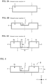
- FIG. 3A is the A-A cross-sectional view of FIG. 2
- FIG. 3B is the C-C cross-sectional view of FIG. 2
- FIG. 3C is the B-B cross-sectional view of FIG. 2 .
- the structural member 10 shown in FIG. 2 includes the edge portion T 1 and the edge portion T 2 opposing the edge portion T 1 . Also, when an axis direction connecting the edge portion T 1 and the edge portion T 2 is regarded as an X axis direction, the structural member 10 includes, along the X axis direction, a region A including the edge portion T 1 , and a region B located on the edge portion T 2 side than the region A and including the edge portion T 2 . Also, region C, which is an intermediate region between the region A and the region B, may be located therebetween.
- the region A shown in FIG. 2 includes a closed cross-section portion A whose outer rim shape is one closed cross-section A.
- the closed cross-section A shown in FIG. 3A includes the top surface portion 1, the bottom surface portion 2, the first wall portion 3 and the second wall portion 4.
- the term "closed cross-section” means a shape whose outer rim shape in the cross-section is closed (that is, the outer rim is endless, and there is no edge portion in the circumferential direction of the cross-sectional shape), and the term "closed cross-section portion” means a portion including a closed cross-section.
- the bottom surface portion 2 opposes the top surface portion 1
- the first wall section 3 connects the top surface portion 1 and the bottom surface portion 2
- the second wall portion 4 opposes the first wall portion 3, and connects the top surface portion 1 and the bottom surface portion 2.
- the region B shown in FIG. 2 includes a closed cross-section portion B including a closed cross-section B 1 and a closed cross-section B 2 those are connected via a bottom portion 53 constituting a concave portion 5, and are placed apart from each other.
- the closed cross-section B 1 includes the top surface portion 1, the bottom surface portion 2, the first wall portion 3, and the wall portion 51 of the concave portion 5; and the closed cross-section B 2 includes the top surface portion 1, the bottom surface portion 2, the second wall portion 4, and the wall portion 52 of the concave portion 5. Meanwhile, as shown in FIG.
- the region B may include a closed cross-section portion B including an open cross-section B 1 and an open cross-section B 2 those are formed by dividing one closed cross-section B with the concave portion 5. That is, the closed cross-section B 1 may be replaced by the open cross-section B 1 , and the closed cross-section B 2 may be replaced by the open cross-section B 2 .
- the term "open cross-section” means a shape whose outer rim shape in the cross-section is open (that is, the outer rim is an ended shape, and there is an edge portion in the circumferential direction of the cross-sectional shape).
- the depth d B in the Z axis direction of the concave portion 5 in the closed cross-section B may be 50% or more, may be 70% or more, may be 80% or more, and may be 90% or more, with respect to the maximum length h B of the closed cross-section B in the Z axis direction.
- the region C shown in FIG. 2 includes a closed cross-section portion C including a closed cross-section C.
- the shape of closed cross-section C is varied continuously from the closed cross-section A to the closed cross-section B 1 and the closed cross-section B 2 along the +X direction.
- the closed cross-section C shown in FIG. 3B includes the top surface portion 1 with the concave portion 5 formed thereon, the bottom surface portion 2, the first wall portion 3, and the second wall portion 4.
- the closed cross-section B 1 is placed along the inner rim portion of the curved shape
- the closed cross-section B 2 is placed along the outer rim portion of the curved shape. Therefore, the closed cross-section portion of the structural member 10 shown in FIG. 2 branches from the closed cross-section A to the closed cross-section B 1 and the closed cross-section B 2 along the +X direction. Since the material is placed at a far place from the neutral axis of bending in the closed cross-section portion B in FIG. 2 , the second moment of area of the structural member 10 may be increased.
- the closed cross-section portion A and the closed cross-section portion B are included as the closed cross-section portion perpendicular to the X axis, a structural member with a good balance between bending strength and lightweight property may be obtained.
- a load in the +Y direction is applied to the center of the member (such as a ball joint) installed to the edge portion T 1 shown in FIG. 2
- bending force that displaces the center position thereof toward the edge portion T 3 side is applied, and the first wall portion 3 is subjected to a compressive load.
- the closed cross-section portion in the present disclosure functions as a force-resistant portion that suppresses the out-of-plane deformation of the first wall portion 3 due to this compressive load.
- the present disclosure it is possible to suppress the shape collapse of the closed cross-section portion B by placing the closed cross-section portion B, with good bending strength, in the region B which is relatively strongly affected by the compressive load. Also, while the bending strength of closed cross-section portion B is better than that of closed cross-section portion A, it is disadvantageous in terms of lightweight property. Therefore, it is possible to improve the lightweight property by placing the closed cross-section portion A in the region A which is relatively not affected by the compressive load. Thereby, a structural member with a good balance between bending strength and lightweight property may be obtained.
- Region A in the present disclosure is a region including the edge portion T 1 , as shown in FIG. 5 . Also, the region A includes a closed cross-section portion A at the boundary between the region A and another adjacent region (such as region B, region C or region D).
- an arbitrary axis parallel to the X axis direction and crosses the edge portion T 2 is regarded as an X 1 axis
- a length of the region A in the X 1 axis is regarded as L AX
- a length of the region A in the Y axis direction at an arbitrary point P A on the X 1 axis in the region A is regarded as L AY .
- the X 1 axis may be the axis which crosses the branch point described below.
- the arbitrary point P A may be the intersection point of the X 1 axis and the edge portion T 1 .
- the ratio (L AX /L AY ) of L AX with respect to L AY satisfies, for example, 0.5 or more, may satisfy 1.0 or more, and may satisfy 1.5 or more, on at least any one of the point P A .
- L AX /L AY satisfies, for example, 4.0 or less, may satisfy 3.5 or less, and may satisfy 3.0 or less, on at least any one of the point P A .
- the L AX /L AY is too high, it is possible that the bending strength improving effect due to the region B is reduced.
- a length of the region A in the X 1 axis is regarded as L AX
- a length of the region B in the X 1 axis is regarded as L BX
- a length of the region C in the X 1 axis is regarded as L CX .
- the ratio (L AX /L TX ) of L AX with respect to the sum (L TX ) of L BX and Lex, for example, is 0.10 or more, and may be 0.30 or more.
- L AX /L TX for example, is 1.87 or less, and may be 0.95 or less.
- the distance from the edge portion T 1 to the edge portion T 2 in the X 1 axis for example, is 300 mm or more, and 600 mm or less.
- the region A includes a closed cross-section portion A whose outer rim shape is one closed cross-section A. That is, the closed cross-section portion A includes only one closed cross-section A as a closed cross-section identified from its outer rim.
- the closed cross-section is defined by the shape of the outer rim as described above. Therefore, even if the closed cross-section is divided into several regions within thereof by the installation of a partition wall and so on inside one closed cross-section, the closed cross-section is regarded as one closed cross-section. Meanwhile, for example, the structural member 10 shown in FIGS.
- closed cross-section portion whose outer rim shape includes two closed cross-sections on the edge portion T 1 side.
- a closed cross-section portion does not correspond to the closed cross-section portion A in the present disclosure.
- the closed cross-section A is a closed cross-section wherein a predetermined concave portion is not provided.
- predetermined concave portion means a concave portion whose depth of the concave portion in the closed cross-section A, in the Z axis direction, is 50% or more with respect to the maximum length of the closed cross-section A in the Z axis direction.
- the shape of the outer rim of the closed cross-section A is not particularly limited, and examples thereof may include a polygon such as a rectangle; and a round shape such as an exact circle and an oval shape.
- the polygon in the present disclosure includes not only a strict polygon, but also a shape in which the part corresponding to the corner of the polygon is formed into an arc shape.
- the closed cross-section A shown in FIGS. 6 includes the top surface portion 1, the bottom surface portion 2, the first wall portion 3 and the second wall portion 4.
- each side of the closed cross-section is shown as a straight line, each side of the closed cross-section in the present disclosure is not limited to a straight line, and may be a curve.
- the region A preferably includes many regions wherein the closed cross-section portion A is formed, and may include the closed cross-section portions A throughout the X axis direction.
- the closed cross-section portion A may be constituted with one member.
- a structural member is obtained, for example, by carrying out a pressing process on one sheet of metal and carrying out a fixing process to form a closed cross-section.
- the fixing process may include, a method wherein sheets of metal are subjected to a fixing process. More specific examples of the fixing process may include welding such as spot welding, laser welding, and arc welding; mechanical joints such as riveting, crimped joints, and bolted joints; and adhesion with an adhesive.
- a fixed portion is formed by the fixing process.
- the closed cross-section portion A may be constituted with two or more members.
- a structural member is obtained, for example, by carrying out a pressing process on two or more sheets of metal to join the different sheets of metal, and carrying out a fixing process to form a closed cross-section.
- the fixing process is similar to those described above.
- Each of the closed cross-section portions A shown in FIGS. 7A to 7D are closed cross-section portions constituted with one member.
- a fixed portion is formed in the top surface portion 1
- a fixed portion is formed in the bottom surface portion 2
- a fixed portion is formed in the first wall portion 3
- a fixed portion is formed in the second wall portion 4.
- the fixed portions are formed throughout the top surface portion, bottom surface portion, first wall portion or second wall portion, the fixed portion may be formed in at least a part thereof. Also, in FIGS. 8A to 11B described later, although the fixed portion is formed at the place where the members are placed so as to overlap each other, the description of the fixed portion is omitted.
- FIGS. 8A to 8F show a joining method wherein two members are joined together on the outer rime line at the fixed portions.
- S 1 to S 4 correspond to any one of the top surface portion, bottom surface portion, first wall portion, or second wall portion, respectively.
- S 1 is the top surface portion
- S 3 corresponds to the bottom surface portion
- one of S 2 and S 4 corresponds to the first wall portion
- the other corresponds to the second wall portion.
- S 1 and S 3 are indicated longer than S 2 and S 4 for convenience, S 1 and S 3 may be shorter and may be the same as S 2 and S 4 .
- S 1 to S 4 in FIGS. 9A to 11B described below.
- a member constituting S 1 and a member constituting S 2 , S 3 and S 4 are used in the closed cross-section portions A shown in FIGS. 8A to 8D .
- the member constituting S 1 may be placed and joined so as to cover the member constituting S 2 , S 3 and S 4 , and as shown in FIGS.
- the member constituting S 2 , S 3 and S 4 may be placed and joined so as to cover the member constituting S 1 .
- FIGS. 8A and 8C there are two fixed portions fixing the member constituting S 1 and the member constituting S 2 , S 3 and S 4 , and in both of the two fixed portions, the members are uniformed so that the member constituting S 1 is placed on the outer side than the member constituting S 2 , S 3 and S 4 . Meanwhile, in FIGS.
- the member constituting S 1 and S 4 are placed on the outer side than the member constituting S 2 and S 3 in the fixed portion in the S 2 side, and the member constituting S 1 and S 4 are placed on the inner side than the member constituting S 2 and S 3 in the fixed portion in the S 4 side, and are not uniformed.
- the member placed on the inner side and the member placed on the outer side may or may not be uniformed.
- a member constituting S 1 S 2 and S 4 and a member constituting S 2 S 3 and S 4 are used, and S 2 and S 4 are formed with two members, respectively.
- the fixed portion may be formed by jostling the members (joining the end surfaces of the members together), not by overlaying the members.
- each of the closed cross-section portions A shown in FIGS. 9A to 9E are also closed cross-section portions constituted with two members.
- FIGS. 9A to 9E show a joining method wherein at least one of the two members includes a flange portion at the fixed portion.
- a member constituting S 1 and S 4 and a member constituting S 2 and S 3 are used, and S 2 and S 4 respectively include a flange portion.
- a member constituting S 1 S 2 and S 4 and a member constituting S 3 are used, and S 2 and S 4 respectively include a flange portion.
- a member constituting S 1 and a member constituting S 2 , S 3 and S 4 are used, and S 1 includes two flange portions.
- S 1 includes two flange portions.
- a member constituting S 1 S 2 and S 4 and a member constituting S 2 S 3 and S 4 are used, and S 2 and S 4 in each member respectively include a flange portion.
- a member constituting S 1 and S 4 and a member constituting S 2 and S 3 are used, and S 2 and S 3 respectively include a flange portion.
- S 2 and S 3 respectively include a flange portion.
- the site where the flange portion is formed is not particularly limited. Also, when multiple fixed portions are provided, for example, the joining method shown in FIGS. 8A to 8F and the joining method shown in FIGS. 9A to 9E may be combined.
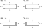
- Each of the closed cross-section portions A shown in FIGS. 10A to 10B are closed cross-section portions constituted with four members.
- members constituting S 1 to S 4 respectively are used.
- FIG. 10A the member constituting S 2 is placed and joined so as to cover the member constituting S 1 and the member constituting S 4 .
- This joining method is similar to the joining method of the members constituting S 1 in FIG. 8A .
- the joining method of each member is not limited to the joining method shown in FIG. 8A ; the joining method shown in FIGS. 8B to 8F may be adopted, or the joining method using a flange portion as shown in FIGS. 9A to 9E may be adopted. Also, the joining method of each member may be the same and may be different from each other.
- the member constituting the side of the closed cross-section A may include a closed cross-sectional structure.
- S 2 for example, the first wall portion
- multiple members constituting the side of the closed cross-section A may include a closed cross-sectional structure.
- S 2 and S 4 for example, the first wall portion and the second wall portion respectively include a closed cross-sectional structure.
- the inside of the closed cross-sectional structure may be hollow, and may be filled with fillers such as resin.
- the region B in the present disclosure is a region located on the edge portion T 2 side than the region A and including the edge portion T 2 .
- the region B is a region on the +X direction side than the boundary between the region B and other adjacent regions (such as region A, region C or region D).
- the region B includes a closed cross-section portion B at the boundary between the region B and other adjacent regions.
- the region B includes a closed cross-section portion B satisfying the following (i) or (ii).
- the closed cross-section portion B satisfying the (i) includes a closed cross-section B 1 and a closed cross-section B 2 those are connected via a bottom portion constituting a concave portion, and are placed apart from each other.
- the closed cross-section portion B satisfying the (i) includes a closed cross-section B 1 and a closed cross-section B 2 .
- the shape of the outer rim of the closed cross-section B 1 and the closed cross-section B 2 is not particularly limited, and examples thereof may respectively include a polygon such as a rectangle; and a round shape such as an exact circle and an oval shape.
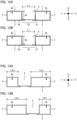
- the closed cross-section portion B shown in FIG. 12A includes a closed cross-section B 1 and a closed cross-section B 2 those are connected via a bottom portion 53 constituting the concave portion 5, and are placed apart from each other.
- the closed cross-section B 1 includes the top surface portion 1, the bottom surface portion 2, the first wall portion 3 and the wall portion 51 of the concave portion 5; and the closed cross-section B 2 includes the top surface portion 1, the bottom surface portion 2, the second wall portion 4, and the wall portion 52 of the concave portion 5.
- the length L ⁇ of the concave portion 5 in the Y axis direction is preferably enlarged along the +X direction (the direction from the back side of the paper toward the front side in FIG. 12A ).
- the distance between the closed cross-section B 1 and the closed cross-section B 2 preferably increases along the +X direction.
- the closed cross-section B 1 is placed along an inner rim portion of the curve
- the closed cross-section B 2 is placed along an outer rim portion of the curve
- the closed cross-section B 1 and closed cross-section B 2 are further separated from each other along the +X direction.
- the bottom portion 53 of the concave portion 5 may be placed on the bottom surface portion 2 side (in the -Z direction) position, in the cross-section perpendicular to the X axis direction, with respect to the top surface portion 1.
- the bottom portion of the concave portion may be placed on the top surface portion side (in the +Z direction) position, in the cross-section perpendicular to the X axis direction, with respect to the bottom surface portion.
- the bottom portion 53 of the concave portion 5 includes a site formed continuously from the wall portion 51 and the wall portion 52. At this bottom portion 53, the bottom surface portion 2 is formed discontinuously.
- the bottom portion 53 of the concave portion 5 includes a site formed continuously from the bottom surface portion 2. At this bottom portion 53, there is a discontinuity between the site that is continuously formed from the wall portion 51 and the site that is continuously formed from the wall portion 52.
- the length L B1Y of the closed cross-section B 1 in the Y axis direction and the length L B2Y of the closed cross-section B 2 in the Y axis direction may be the same, and may be different.
- L B1Y is larger than L B2Y .
- L B2Y is larger than L B1Y .
- the closed cross-section portion B satisfying the (ii) includes an open cross-section B 1 and an open cross-section B 2 those are formed by dividing one closed cross-section B with the concave portion.
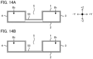
- the closed cross-section portion B shown in FIG. 14A includes an open cross-section B 1 and an open cross-section B 2 those are formed by dividing one closed cross-section B with the concave portion 5. Also, as shown in FIG. 14A
- the depth d B of the concave portion 5 in the closed cross-section B, in the Z axis direction may be 50% or more, may be 70% or more, may be 80% or more, and may be 90% or more, with respect to the maximum length h B of the closed cross-section B in the Z axis direction.
- the closed cross-section B includes an open cross-section B 1 and an open cross-section B 2 , there is no contact between the bottom portion 53 of the concave portion 5 and the bottom surface portion 2, as shown in FIG. 14A . Also, as shown in FIGS.
- the bottom portion 53 of the concave portion 5 may be placed on the bottom surface portion 2 side (in the -Z direction) position, in the cross-section perpendicular to the X axis direction, with respect to the top surface portion 1. Meanwhile, although not particularly shown in the figures, the bottom portion of the concave portion may be placed on the top surface portion side (in the +Z direction) position, in the cross-section perpendicular to the X axis direction, with respect to the bottom surface portion. Also, the depth d B may be approximately 100% with respect to the maximum length h B . In this case, as shown in FIG. 14B , the bottom portion 53 of the concave portion 5 and the bottom surface portion 2 may be in contact.
- the closed cross-section portion B includes the closed cross-section B 1 and the closed cross-section B 2 . Also, when the bottom portion 53 of the concave portion 5 and the bottom surface portion 2 is in contact, a fixed portion fixing these two may be formed.
- the closed cross-section portion B may be constituted with one member, and may be constituted with two or more members. With the exception of the concave portion, these matters are similar to those described for the closed cross-section portion A described above.
- the structural member in the present disclosure may include a region C located between the region A and the region B, in the X axis direction.
- the region C is a region wherein, along a direction (+X direction) from the edge portion T 1 to the edge portion T 2 , and the shape of the closed cross-section portion, in the cross-section perpendicular to the X axis direction of the structural member, varies continuously from the closed cross-section portion A to the closed cross-section portion B. That is, along the +X direction, the closed cross-section portion of the structural member is formed so as the cross-sectional shape varies continuously from the closed cross-section portion A to the closed cross-section portion B.
- the region C includes a closed cross-section portion C including a closed cross-section C.
- the closed cross-section portion C may include only one closed cross-section C as a closed cross-section identified from its outer rim.
- the shape of the closed cross-section C is not particularly limited, and with the exception of the concave portion, it is similar to those described for the closed cross-section A described above.
- the closed cross-section C shown in FIG. 3B includes the top surface portion 1 with the concave portion 5 formed thereon, the bottom surface portion 2, the first wall portion 3, and the second wall portion 4. Also, the depth of the concave portion 5 in the closed cross-section C is regarded as de.
- the region C includes a branch point (branch point of the closed cross-section) located at the boundary of the closed cross-section portion A and the closed cross-section portion C.
- FIG. 15A is a schematic plan view illustrating an example of the structural member in the present disclosure
- FIG. 15B is a Cx-Cx cross-sectional view of FIG.15A
- the Cx-Cx axis is an axis parallel to the X axis direction and crosses the branch point located at the boundary of the closed cross-section portion A and the closed cross-section portion C.
- the depth d C of the concave portion 5 in the region C (closed cross-section C) increases continuously along the +X direction (the direction from edge portion T 1 to the edge portion T 2 ).
- the depth d C at the boundary between the region A and the region C is 0, the depth d C increases along the +X direction, and the depth d C at the boundary between the region B and the region C coincides with the depth d B (the depth of concave portion 5 in closed cross-section B).
- the boundary line between the region C and the region A is a line parallel to the Y axis direction which crosses the boundary portion on the Cx-Cx axis, that is, the branch point.
- the boundary line between the region C and the region B is a line parallel to the Y axis direction which crosses the boundary portion on the Cx-Cx axis.
- the region C includes the closed cross-section portion C all across the region from the boundary with the region A to the boundary with the region B, in the X axis direction.
- the closed cross-section portion C may be constituted with one member, and may be constituted with two or more members. With the exception of the concave portion, these matters are similar to those described for the closed cross-section portion A described above.
- the structural member in the present disclosure may not include the region C.
- the structural member is a structural member which is discontinuously varied from the closed cross-section A in the region A to the closed cross-section B 1 and the closed cross-section B 2 in the region B, along the direction from the edge portion T 1 to the edge portion T 2 (+X direction).
- the boundary between the region A and the region B is the boundary between the closed cross-section portion A and the closed cross-section portion B.
- the structural member in the present disclosure may be provided with one or a plurality of a region not shown in the figures including an open cross-section, or a region not shown in the figures including a closed cross-section formed discontinuously to the closed cross-section A, the closed cross-section B 1 , and the closed cross-section B 2 , along the direction from edge portion T 1 to edge portion T 2 (+X direction). That is, the region A and the region B are placed apart from each other, and one or a plurality of a region including an open cross-section, or a region including a closed cross-section formed discontinuously to the closed cross-section A, the closed cross-section B 1 , and the closed cross-section B 2 , between the region A and the region B.
- region D a region where the all across the region has an open cross-section is regarded as a region D. That is, the region D is located between the region A and the region B, and includes the open cross-section all across the region. Also, in a plane view of the structural member, the closed cross-section portion A branches toward the closed cross-section portion B, and the region D includes a branch point located at the boundary with the closed cross-section portion A.
- the cross-sectional shape of the region D is a shape without the bottom portion 2 located in the region C.
- the boundary line between the region D and the region A is a line parallel to the Y axis direction which crosses the branch point.
- the depth d D coincides with the depth d B at the boundary between the region D and the region B.
- the boundary line between the region D and the region B is a line parallel to the Y axis which crosses the boundary portion on the D X -D X axis.
- the structural member in the present disclosure preferably includes a curved shape in plan view.
- the curved shape is a shape in which the length of structural member 10 in the Y axis direction is enlarged along the +X direction. That is, when the length of structural member 10, in the Y axis direction, at relatively the edge portion T 1 side position is regarded as L SY1 , and the length of structural member 10, in the Y axis direction, at relatively the edge portion T 2 side position is regarded as L SY2 , the curved shape is a shape wherein L SY1 ⁇ L SY2 . Strictly speaking, the center of curvature of the inner rim portion ⁇ of the curved shape is located on the outer side of the structural member 10.
- the first wall portion 3 may be placed along the inner rim portion ⁇ of the curved shape. Meanwhile, the second wall portion 4 may be placed along the outer rim portion ⁇ of the curved shape.
- Material constituting the structural member in the present disclosure is not particularly limited, and examples thereof may include metal material such as steel, aluminum alloy, and magnesium alloy; and resin material including resin and fiber such as glass fiber and carbon fiber (for example, CFRP). Also, the structural member may be a composite material of metal material and resin material.
- the metal plate such as a steel plate
- the tensile strength of the metal plate such as a steel plate is not particularly limited, and may be, for example, 780 MPa or more, and may be 980 MPa or more.
- the thickness of the metal plate such as a steel plate is, for example, 1 mm or more and 3 mm or less.
- the structural member in the present disclosure is not particularly limited, and examples thereof may include an automotive application. That is, the structural member may be a structural member of an automobile. Examples of the structural member of an automobile may include suspension members such as a front lower arm, a rear lower arm, a front upper arm and a rear upper arm.
- FIG. 17 is a schematic plan view illustrating an example of the structural member in the present disclosure, and specifically, it is a schematic plan view illustrating an example of a front lower arm.
- the maximum length of the front lower arm in the front and rear direction of the vehicle (left and right direction of the paper in FIG. 17 ) is, for example, 260 mm or more and 460 mm or less.
- the maximum length of the front lower arm in the vehicle width direction is, for example, 300 mm or more and 600 mm or less.
- the maximum length of the front lower arm in the vehicle height direction is, for example, 30 mm or more and 100 mm or less.
- the structural member in the present disclosure may be used for, for example, mobile objects such as motorcycles, ships and aircraft; and for building structures.
- the present disclosure is not limited to the embodiments.
- the embodiments are exemplification, and any other variations are intended to be included in the technical scope of the present disclosure if they have substantially the same constitution as the technical idea described in the claim of the present disclosure and offer similar operation and effect thereto.
- FIG. 18A is a schematic plan view of the shape model of the structural member prepared in Example 1
- FIG. 18B is an A-A cross-sectional view of FIG. 18A
- FIG. 18C is a B-B cross-sectional view of FIG. 18A .
- the structural member 10 shown in FIG. 18A includes the edge portion T 1 , the edge portion T 2 , and the edge portion T 3 described above, and further includes the region A, the region B, and the region C.
- the midpoint of the edge portion T 1 in the Y axis direction was regarded as point P 1 .
- the L AX /L AY was set to 1.0.
- L AX was regarded as the length of the region A on the X 1 axis (not shown in the figures) which crosses the branch point located at the boundary of the closed cross-section portion A and the closed cross-section portion C
- L AY was regarded as the length of the region A in the Y axis direction at the crossing point of the X 1 axis and the edge portion T 1 .
- the region A of the structural member 10 shown in FIG. 18A includes the closed cross-section portion A including the closed cross-section A including the top surface portion 1, the bottom surface portion 2, the first wall portion 3 and the second wall portion 4.
- the region B in the structural member 10 shown in FIG. 18A includes the closed cross-section portion B including the closed cross-section B 1 and the closed cross-section B 2 placed apart from each other.
- FIGS. 19A and 19B The shape model of the structural member shown in FIGS. 19A and 19B was prepared on a computer using CAD (Computer Aided Design) software.
- FIG. 19A is a schematic plan view of the shape model of the structural member prepared in Reference Example 1
- FIG. 19B is a B-B cross-sectional view of FIG. 19A .
- a shape model of the structural member was prepared in the same manner as in Example 1, except that the closed cross-section portion B was formed all across the region along the X axis direction, as shown in FIGS. 19A and 19B .
- FIGS. 20A and 20B The shape model of the structural member shown in FIGS. 20A and 20B was prepared on a computer using CAD (Computer Aided Design) software.
- FIG. 20A is a schematic plan view of the shape model of the structural member prepared in Comparative Example 1
- FIG. 20B is an A-A cross-sectional view of FIG. 20A .
- a shape model of the structural member was prepared in the same manner as in Example 1, except that, instead of the closed cross-section portion A, the closed cross-section portion B, and the closed cross-section portion C in Example 1, the open cross-section portion including the top surface portion 11 with the concave portion 15 formed thereon, the first wall portion 13 and the second wall portion 14, as shown in FIGS. 20A and 20B , was formed.
- Example 1 included only a closed cross-section portion B, while the structural member in Example 1 included a closed cross-section portion A with a good lightweight property, in addition to the closed cross-section portion B. This is presumed to be the reason why the structural member with a good balance between bending strength and lightweight property was obtained.
Landscapes
- Engineering & Computer Science (AREA)
- Mechanical Engineering (AREA)
- Body Structure For Vehicles (AREA)
- Vehicle Body Suspensions (AREA)
- Rod-Shaped Construction Members (AREA)
Abstract
Description
- The present disclosure relates to a structural member.
- For example, a front lower arm, which is a suspension member of an automobile, is an L-shaped member and requires bending strength in the front and rear direction of the vehicle (see
Patent Literature 1 for example). When a car tire drives over a curb or a step, a large load is applied to the tire in the front and rear direction (from front to rear) of the vehicle. This load is applied from the tire to the outer edge portion, in the car width direction, of the front lower arm, via the knuckle arm, etc., and acts as a bending force that bends this outer edge portion toward the inner edge portion side. When the above bending force is large due to the load being large, the outer edge portion is plastically deformed toward the inner edge portion side. When this plastic deformation occurs, the alignment of the tires will change, affecting the ride quality or handling ease of the vehicle. Also, a larger bending force may cause buckling of the front lower arm. When such buckling occurs, the alignment of the tires is greatly misaligned, making it impossible for the car to run, and the car cannot be brought to a repair shop by self-driving. - Patent literature 1:
WO 2019/103152 - To increase the deformation strength of the front lower arm, it is necessary to increase the second moment of area, with respect to the bending force, of the front lower arm. For this reason, conventional designs have been devised to enlarge the width of each portion of the front lower arm and to give a predetermined shape to the edge portion of the member.
- Meanwhile, with the background of global environmental problems, it is necessary to make automobiles lighter in order to reduce CO2 emissions. In recent years, the front lower arm has especially been made thinner and thinner in order to reduce weight. Due to the thinning of the front lower arm, when the front lower arm is bent and deformed in the front and rear direction of the vehicle, out-of-plane deformation (deformation in the direction of vehicle height) tends to occur, and the originally designed cross-sectional shape may be lost. When the cross-sectional shape collapses, it becomes difficult to obtain high bending strength. Similar challenges exist not only for components applied to automobiles, but also for structural members used in other structures such as mobile objects or buildings.
- The present disclosure has been made in view of the above circumstances, and a main object of the present disclosure is to provide a structural member with a good balance between bending strength and lightweight property.
-
- [1] A structural member comprising an edge portion T1 and an edge portion T2 opposing the edge portion T1 in plan view in height direction (Z axis direction);
- when an axis direction connecting the edge portion T1 and the edge portion T2 is regarded as an X axis direction, the structural member includes, along the X axis direction, a region A including the edge portion T1, and a region B located on the edge portion T2 side than the region A and including the edge portion T2;
- in a cross-section perpendicular to the X axis direction, the region A includes a closed cross-section portion A whose outer rim shape is one closed cross-section A; and
- the region B includes a closed cross-section portion B satisfying the following (i) or (ii):
- (i) in a cross-section perpendicular to the X axis direction, the closed cross-section portion B includes a closed cross-section B1 and a closed cross-section B2 those are connected via a bottom portion constituting a concave portion, and are placed apart from each other, or
- (ii) in a cross-section perpendicular to the X axis direction, the closed cross-section portion B incudes an open cross-section B1 and an open cross-section B2 those are formed by dividing one closed cross-section B with a concave portion, and in the closed cross-section B, a depth of the concave portion in the Z axis direction is 50% or more with respect to a maximum length of the closed cross-section B in the Z axis direction.
- [2] The structural member according to [1], wherein the closed cross-section portion B satisfies the (i).
- [3] The structural member according to [1], wherein the closed cross-section portion B satisfies the (ii).
- [4] The structural member according to any one of [1] to [3], wherein, along a direction (+X direction) from the edge portion T1 to the edge portion T2, a shape of a closed cross-section portion, in a cross-section perpendicular to the X axis direction of the structural member, is formed so as to be varied continuously from the closed cross-section portion A to the closed cross-section portion B.
- [5] The structural member according to any one of [1] to [4], wherein, in plan view in the height direction (Z axis direction), when an axis direction orthogonal to the X axis direction is regarded as an Y axis direction, and a length of the structural member in the Y axis direction is regarded as LSY, the structural member has a curved shape in which the LSY is enlarged along a direction (+X direction) from the edge portion T1 to the edge portion T2; and
the closed cross-section B1 is placed along an inner rim portion of the curved shape, and the closed cross-section B2 is placed along an outer rim portion of the curved shape. - [6] The structural member according to any one of [1] to [5], wherein, in plan view in the height direction (Z axis direction), when an axis direction orthogonal to the X axis direction is regarded as an Y axis direction, an arbitrary axis parallel to the X axis direction and crosses the edge portion T2 is regarded as an X1 axis, a length of the region A in the X1 axis is regarded as LAX, and a length of the region A in the Y axis direction at an arbitrary point PA on the X1 axis in the region A is regarded as LAY, LAX/LAY satisfies 1.0 or more and 4.0 or less at least at any one of the point PA.
- [7] The structural member according to any one of [1] to [6], wherein the closed cross-section portion B is constituted with one member.
- [8] The structural member according to any one of [1] to [6], wherein the closed cross-section portion B is constituted with two or more members.
- [9] The structural member according to any one of [1] to [8], wherein the structural member is a structural member of an automobile.
- [10] The structural member according to any one of [1] to [9], wherein the structural member is a front lower arm.
- [11] The structural member according to any one of [1] to [10], wherein at least a steel plate is used as a material constituting the structural member, and a tensile strength of the steel plate is 780 MPa or more.
- The structural member in the present disclosure has an effect that the structural member has a good balance between bending strength and lightweight property.
-
-
FIG. 1 is a schematic plan view illustrating an example of the structural member in the present disclosure. -
FIG. 2 is a schematic plan view illustrating an example of the structural member in the present disclosure. -
FIGS. 3A to 3C are schematic cross-sectional views of the structural member shown inFIG.2 . -
FIG. 4 is a schematic cross-sectional view illustrating an example of the closed cross-section portion B in the present disclosure. -
FIG. 5 is a schematic plan view illustrating an example of the structural member in the present disclosure. -
FIG. 6 is a schematic cross-sectional view illustrating an example of the closed cross-section portion A in the present disclosure. -
FIGS. 7A to 7D are schematic cross-sectional views illustrating an example of the closed cross-section portion A in the present disclosure. -
FIGS. 8A to 8F are schematic cross-sectional views illustrating an example of the closed cross-section portion A in the present disclosure. -
FIGS. 9A to 9E are schematic cross-sectional views illustrating an example of the closed cross-section portion A in the present disclosure. -
FIGS. 10A to 10B are schematic cross-sectional views illustrating an example of the closed cross-section portion A in the present disclosure. -
FIGS. 11A to 11B are schematic cross-sectional views illustrating an example of the closed cross-section portion A in the present disclosure. -
FIGS. 12A to 12B are schematic cross-sectional views illustrating an example of the closed cross-section portion B in the present disclosure. -
FIGS. 13A to 13B are schematic cross-sectional views illustrating an example of the closed cross-section portion B in the present disclosure. -
FIGS. 14A to 14B are schematic cross-sectional views illustrating an example of the closed cross-section portion B in the present disclosure. -
FIG. 15A is a schematic plan view andFIG. 15B is a cross-sectional view illustrating an example of the structural member in the present disclosure. -
FIG. 16 is a schematic plan view illustrating an example of the structural member in the present disclosure. -
FIG. 17 is a schematic plan view illustrating an example of the structural member in the present disclosure. -
FIG. 18A is a schematic plan view andFIGS. 18B to 18C are schematic cross-sectional views of a shape model of the structural member prepared in Example 1. -
FIG. 19A is a schematic plan view andFIG. 19B is a schematic cross-sectional view of a shape model of the structural member prepared in Reference Example 1. -
FIG. 20A is a schematic plan view andFIG. 20B is a schematic cross-sectional view of a shape model of the structural member prepared in Comparative Example 1. -
FIG. 21 illustrates the results of the evaluation in Examples 1 to 3, Reference Example 1 and Comparative Example 1. - The structural member in the present disclosure will be hereinafter described in detail. Each figure shown below exaggerates the size and shape of each part appropriately for ease of understanding. Also, in each figure, the hatching or sign may be omitted for convenience.
-
FIG. 1 is a schematic plan view illustrating an example of the structural member in the present disclosure, and specifically illustrating an example of a front lower arm. Astructural member 10, shown inFIG. 1 , is a member configured to connect the lower part of the knuckle (not shown in the figure), which rotatably supports the wheel on which the tire is installed, to the car body. An edge portion T1 on one end of thestructural member 10 indicates the installation position of the ball joint which is attached to the knuckle. Also, an edge portion T2 opposing the edge portion T1 in the X axis direction, and an edge portion T3 located on the + Y direction than the edge portion T2, indicate the connection points with the body members such as the subframe (not shown in the figure). Thestructural member 10 is secured to the body member via a bush joint (not shown in the figure), for example, provided at the edge portion T2 and edge portion T3. - Also, as shown in
FIG. 1 , thestructural member 10 is an L-shaped member. Specifically, when the length ofstructural member 10 in the Y axis direction is regarded as LSY, thestructural member 10 has a curved shape in which the LSY is enlarged along the +X direction. In thestructural member 10, the side of the curved shape with a large radius of curvature may be referred to as an outer side of the curvature, and the side of the curved shape with a small radius of curvature may be referred to as an inner side of the curvature. -
FIG. 2 is a schematic plan view illustrating an example of the structural member in the present disclosure, andFIGS. 3A to 3C are schematic cross-sectional views of the structural member shown inFIG.2 . Specifically,FIG. 3A is the A-A cross-sectional view ofFIG. 2 ,FIG. 3B is the C-C cross-sectional view ofFIG. 2 , andFIG. 3C is the B-B cross-sectional view ofFIG. 2 . - The
structural member 10 shown inFIG. 2 includes the edge portion T1 and the edge portion T2 opposing the edge portion T1. Also, when an axis direction connecting the edge portion T1 and the edge portion T2 is regarded as an X axis direction, thestructural member 10 includes, along the X axis direction, a region A including the edge portion T1, and a region B located on the edge portion T2 side than the region A and including the edge portion T2. Also, region C, which is an intermediate region between the region A and the region B, may be located therebetween. - As shown in
FIG. 3A , in the cross-section perpendicular to the X axis direction, the region A shown inFIG. 2 includes a closed cross-section portion A whose outer rim shape is one closed cross-section A. The closed cross-section A shown inFIG. 3A includes thetop surface portion 1, thebottom surface portion 2, thefirst wall portion 3 and thesecond wall portion 4. In the present disclosure, the term "closed cross-section" means a shape whose outer rim shape in the cross-section is closed (that is, the outer rim is endless, and there is no edge portion in the circumferential direction of the cross-sectional shape), and the term "closed cross-section portion" means a portion including a closed cross-section. Also, InFIG. 3A , thebottom surface portion 2 opposes thetop surface portion 1, thefirst wall section 3 connects thetop surface portion 1 and thebottom surface portion 2, thesecond wall portion 4 opposes thefirst wall portion 3, and connects thetop surface portion 1 and thebottom surface portion 2. - As shown in
FIG. 3C , in the cross-section perpendicular to the X axis direction, the region B shown inFIG. 2 includes a closed cross-section portion B including a closed cross-section B1 and a closed cross-section B2 those are connected via abottom portion 53 constituting aconcave portion 5, and are placed apart from each other. InFIG. 3C , the closed cross-section B1 includes thetop surface portion 1, thebottom surface portion 2, thefirst wall portion 3, and thewall portion 51 of theconcave portion 5; and the closed cross-section B2 includes thetop surface portion 1, thebottom surface portion 2, thesecond wall portion 4, and thewall portion 52 of theconcave portion 5. Meanwhile, as shown inFIG. 4 , the region B may include a closed cross-section portion B including an open cross-section B1 and an open cross-section B2 those are formed by dividing one closed cross-section B with theconcave portion 5. That is, the closed cross-section B1 may be replaced by the open cross-section B1, and the closed cross-section B2 may be replaced by the open cross-section B2. In the present disclosure, the term "open cross-section" means a shape whose outer rim shape in the cross-section is open (that is, the outer rim is an ended shape, and there is an edge portion in the circumferential direction of the cross-sectional shape). Also, the depth dB in the Z axis direction of theconcave portion 5 in the closed cross-section B may be 50% or more, may be 70% or more, may be 80% or more, and may be 90% or more, with respect to the maximum length hB of the closed cross-section B in the Z axis direction. - As shown in
FIG. 3B , the region C shown inFIG. 2 includes a closed cross-section portion C including a closed cross-section C. The shape of closed cross-section C is varied continuously from the closed cross-section A to the closed cross-section B1 and the closed cross-section B2 along the +X direction. The closed cross-section C shown inFIG. 3B includes thetop surface portion 1 with theconcave portion 5 formed thereon, thebottom surface portion 2, thefirst wall portion 3, and thesecond wall portion 4. - Here, as shown in
FIG. 2 , the closed cross-section B1 is placed along the inner rim portion of the curved shape, and the closed cross-section B2 is placed along the outer rim portion of the curved shape. Therefore, the closed cross-section portion of thestructural member 10 shown inFIG. 2 branches from the closed cross-section A to the closed cross-section B1 and the closed cross-section B2 along the +X direction. Since the material is placed at a far place from the neutral axis of bending in the closed cross-section portion B inFIG. 2 , the second moment of area of thestructural member 10 may be increased. - According to the present disclosure, since the closed cross-section portion A and the closed cross-section portion B are included as the closed cross-section portion perpendicular to the X axis, a structural member with a good balance between bending strength and lightweight property may be obtained. Here, when a load in the +Y direction is applied to the center of the member (such as a ball joint) installed to the edge portion T1 shown in
FIG. 2 , bending force that displaces the center position thereof toward the edge portion T3 side is applied, and thefirst wall portion 3 is subjected to a compressive load. The closed cross-section portion in the present disclosure functions as a force-resistant portion that suppresses the out-of-plane deformation of thefirst wall portion 3 due to this compressive load. In particular, in the present disclosure, it is possible to suppress the shape collapse of the closed cross-section portion B by placing the closed cross-section portion B, with good bending strength, in the region B which is relatively strongly affected by the compressive load. Also, while the bending strength of closed cross-section portion B is better than that of closed cross-section portion A, it is disadvantageous in terms of lightweight property. Therefore, it is possible to improve the lightweight property by placing the closed cross-section portion A in the region A which is relatively not affected by the compressive load. Thereby, a structural member with a good balance between bending strength and lightweight property may be obtained. - Region A in the present disclosure is a region including the edge portion T1, as shown in
FIG. 5 . Also, the region A includes a closed cross-section portion A at the boundary between the region A and another adjacent region (such as region B, region C or region D). - As shown in
FIG. 5 , an arbitrary axis parallel to the X axis direction and crosses the edge portion T2 is regarded as an X1 axis, a length of the region A in the X1 axis is regarded as LAX, and a length of the region A in the Y axis direction at an arbitrary point PA on the X1 axis in the region A is regarded as LAY. The X1 axis may be the axis which crosses the branch point described below. Also, the arbitrary point PA may be the intersection point of the X1 axis and the edge portion T1. The ratio (LAX/LAY) of LAX with respect to LAY satisfies, for example, 0.5 or more, may satisfy 1.0 or more, and may satisfy 1.5 or more, on at least any one of the point PA. When the LAX/LAY is too low, it is possible that the lightweight property improving effect due to the region A is reduced. Meanwhile, LAX/LAY satisfies, for example, 4.0 or less, may satisfy 3.5 or less, and may satisfy 3.0 or less, on at least any one of the point PA. When the LAX/LAY is too high, it is possible that the bending strength improving effect due to the region B is reduced. - Also, as shown in
FIG. 5 , a length of the region A in the X1 axis is regarded as LAX, and a length of the region B in the X1 axis is regarded as LBX, and a length of the region C in the X1 axis is regarded as LCX. The ratio (LAX/LTX) of LAX with respect to the sum (LTX) of LBX and Lex, for example, is 0.10 or more, and may be 0.30 or more. When the LAX/LTX is too low, it is possible that the lightweight property improving effect due to the region A is reduced. Meanwhile, LAX/LTX, for example, is 1.87 or less, and may be 0.95 or less. When the LAX/LTX is too high, it is possible that the bending strength improving effect due to the region B is reduced. Also, the distance from the edge portion T1 to the edge portion T2 in the X1 axis, for example, is 300 mm or more, and 600 mm or less. - In the cross-section perpendicular to the X axis direction, the region A includes a closed cross-section portion A whose outer rim shape is one closed cross-section A. That is, the closed cross-section portion A includes only one closed cross-section A as a closed cross-section identified from its outer rim. Incidentally, the closed cross-section is defined by the shape of the outer rim as described above. Therefore, even if the closed cross-section is divided into several regions within thereof by the installation of a partition wall and so on inside one closed cross-section, the closed cross-section is regarded as one closed cross-section. Meanwhile, for example, the
structural member 10 shown inFIGS. 19A and 19B below includes a closed cross-section portion whose outer rim shape includes two closed cross-sections on the edge portion T1 side. Such a closed cross-section portion does not correspond to the closed cross-section portion A in the present disclosure. Also, the closed cross-section A is a closed cross-section wherein a predetermined concave portion is not provided. The term "predetermined concave portion" means a concave portion whose depth of the concave portion in the closed cross-section A, in the Z axis direction, is 50% or more with respect to the maximum length of the closed cross-section A in the Z axis direction. - The shape of the outer rim of the closed cross-section A is not particularly limited, and examples thereof may include a polygon such as a rectangle; and a round shape such as an exact circle and an oval shape. Incidentally, the polygon in the present disclosure includes not only a strict polygon, but also a shape in which the part corresponding to the corner of the polygon is formed into an arc shape. The closed cross-section A shown in
FIGS. 6 includes thetop surface portion 1, thebottom surface portion 2, thefirst wall portion 3 and thesecond wall portion 4. Incidentally, inFIG. 6 , although each side of the closed cross-section is shown as a straight line, each side of the closed cross-section in the present disclosure is not limited to a straight line, and may be a curve. In the X axis direction, the region A preferably includes many regions wherein the closed cross-section portion A is formed, and may include the closed cross-section portions A throughout the X axis direction. - The closed cross-section portion A may be constituted with one member. Such a structural member is obtained, for example, by carrying out a pressing process on one sheet of metal and carrying out a fixing process to form a closed cross-section. Examples of the fixing process may include, a method wherein sheets of metal are subjected to a fixing process. More specific examples of the fixing process may include welding such as spot welding, laser welding, and arc welding; mechanical joints such as riveting, crimped joints, and bolted joints; and adhesion with an adhesive. A fixed portion is formed by the fixing process.
- Also, the closed cross-section portion A may be constituted with two or more members. Such a structural member is obtained, for example, by carrying out a pressing process on two or more sheets of metal to join the different sheets of metal, and carrying out a fixing process to form a closed cross-section. The fixing process is similar to those described above.
- Each of the closed cross-section portions A shown in
FIGS. 7A to 7D are closed cross-section portions constituted with one member. In the closed cross-section portion A shown inFIG. 7A , a fixed portion is formed in thetop surface portion 1, and in the closed cross-section portion A shown inFIG. 7B , a fixed portion is formed in thebottom surface portion 2, in the closed cross-section portion A shown inFIG. 7C , a fixed portion is formed in thefirst wall portion 3, and in the closed cross-section portion A shown inFIG. 7D , a fixed portion is formed in thesecond wall portion 4. Incidentally, inFIGS 7A to 7D , although the fixed portions are formed throughout the top surface portion, bottom surface portion, first wall portion or second wall portion, the fixed portion may be formed in at least a part thereof. Also, inFIGS. 8A to 11B described later, although the fixed portion is formed at the place where the members are placed so as to overlap each other, the description of the fixed portion is omitted. - Each of the closed cross-section portions A shown in
FIGS. 8A to 8F are closed cross-section portions constituted with two members.FIGS. 8A to 8F show a joining method wherein two members are joined together on the outer rime line at the fixed portions. Also, inFIGS. 8A to 8F , S1 to S4 correspond to any one of the top surface portion, bottom surface portion, first wall portion, or second wall portion, respectively. For example, when S1 is the top surface portion, then S3 corresponds to the bottom surface portion, one of S2 and S4 corresponds to the first wall portion, and the other corresponds to the second wall portion. Also, inFIGS. 8A to 8F , although S1 and S3 are indicated longer than S2 and S4 for convenience, S1 and S3 may be shorter and may be the same as S2 and S4. The same is true for S1 to S4 inFIGS. 9A to 11B described below. In the closed cross-section portions A shown inFIGS. 8A to 8D , a member constituting S1 and a member constituting S2, S3 and S4 are used. As shown inFIGS. 8A and 8C , the member constituting S1 may be placed and joined so as to cover the member constituting S2, S3 and S4, and as shown inFIGS. 8B and 8D , the member constituting S2, S3 and S4 may be placed and joined so as to cover the member constituting S1. InFIGS. 8A and 8C , there are two fixed portions fixing the member constituting S1 and the member constituting S2, S3 and S4, and in both of the two fixed portions, the members are uniformed so that the member constituting S1 is placed on the outer side than the member constituting S2, S3 and S4. Meanwhile, inFIGS. 8B and 8D , there are two fixed portions fixing the member constituting S1 and the member constituting S2, S3 and S4, and in both of the two fixed portions, the members are uniformed so that the member constituting S1 is placed on the inner side than the member constituting S2, S3 and S4. Also, as shown inFIGS. 8A and 8B , a fixed portion may be formed in S2 and S4, and as shown inFIGS. 8C and 8D , a fixed portion may be formed in S1. Also, in the closed cross-section portion A shown inFIG. 8E , a member constituting S1 and S4 and a member constituting S2 and S3 are used. InFIG. 8E , the member constituting S1 and S4 are placed on the outer side than the member constituting S2 and S3 in the fixed portion in the S2 side, and the member constituting S1 and S4 are placed on the inner side than the member constituting S2 and S3 in the fixed portion in the S4 side, and are not uniformed. In this way, when there are multiple fixed portions, the member placed on the inner side and the member placed on the outer side may or may not be uniformed. Also, in the closed cross-section portion A shown inFIG. 8F , a member constituting S1 S2 and S4 and a member constituting S2 S3 and S4 are used, and S2 and S4 are formed with two members, respectively. As shown inFIG. 8F , the fixed portion may be formed by jostling the members (joining the end surfaces of the members together), not by overlaying the members. - Similar to
FIGS. 8A to 8F , each of the closed cross-section portions A shown inFIGS. 9A to 9E are also closed cross-section portions constituted with two members.FIGS. 9A to 9E show a joining method wherein at least one of the two members includes a flange portion at the fixed portion. In the closed cross-section portion A shown inFIG. 9A , a member constituting S1 and S4 and a member constituting S2 and S3 are used, and S2 and S4 respectively include a flange portion. In the closed cross-section portion A shown inFIG. 9B , a member constituting S1 S2 and S4 and a member constituting S3 are used, and S2 and S4 respectively include a flange portion. In the closed cross-section portion A shown inFIG. 9C , a member constituting S1 and a member constituting S2, S3 and S4 are used, and S1 includes two flange portions. In the closed cross-section portion A shown inFIG. 9D , a member constituting S1 S2 and S4 and a member constituting S2 S3 and S4 are used, and S2 and S4 in each member respectively include a flange portion. In the closed cross-section portion A shown inFIG. 9E , a member constituting S1 and S4 and a member constituting S2 and S3 are used, and S2 and S3 respectively include a flange portion. As shown inFIGS. 9A to 9E , the site where the flange portion is formed is not particularly limited. Also, when multiple fixed portions are provided, for example, the joining method shown inFIGS. 8A to 8F and the joining method shown inFIGS. 9A to 9E may be combined. - Each of the closed cross-section portions A shown in
FIGS. 10A to 10B are closed cross-section portions constituted with four members. In the closed cross-section portion A shown inFIGS. 10A to 10B , members constituting S1 to S4 respectively are used. InFIG. 10A , the member constituting S2 is placed and joined so as to cover the member constituting S1 and the member constituting S4. This joining method is similar to the joining method of the members constituting S1 inFIG. 8A . The joining method of each member is not limited to the joining method shown inFIG. 8A ; the joining method shown inFIGS. 8B to 8F may be adopted, or the joining method using a flange portion as shown inFIGS. 9A to 9E may be adopted. Also, the joining method of each member may be the same and may be different from each other. - In the present disclosure, the member constituting the side of the closed cross-section A may include a closed cross-sectional structure. Specifically, in the closed cross-section portion A shown in
FIG. 11A , S2 (for example, the first wall portion) includes a closed cross-sectional structure. Also, multiple members constituting the side of the closed cross-section A may include a closed cross-sectional structure. Specifically, in the closed cross-section portion A shown inFIG. 11B , S2 and S4 (for example, the first wall portion and the second wall portion) respectively include a closed cross-sectional structure. The inside of the closed cross-sectional structure may be hollow, and may be filled with fillers such as resin. - As shown in
FIG.5 , the region B in the present disclosure is a region located on the edge portion T2 side than the region A and including the edge portion T2. Specifically, the region B is a region on the +X direction side than the boundary between the region B and other adjacent regions (such as region A, region C or region D). Also, the region B includes a closed cross-section portion B at the boundary between the region B and other adjacent regions. Also, the region B includes a closed cross-section portion B satisfying the following (i) or (ii). - In the cross-section perpendicular to the X axis direction, the closed cross-section portion B satisfying the (i) includes a closed cross-section B1 and a closed cross-section B2 those are connected via a bottom portion constituting a concave portion, and are placed apart from each other. Also, as a closed cross-section defined by the outer rim thereof, the closed cross-section portion B satisfying the (i) includes a closed cross-section B1 and a closed cross-section B2. The shape of the outer rim of the closed cross-section B1 and the closed cross-section B2 is not particularly limited, and examples thereof may respectively include a polygon such as a rectangle; and a round shape such as an exact circle and an oval shape.
- The closed cross-section portion B shown in
FIG. 12A includes a closed cross-section B1 and a closed cross-section B2 those are connected via abottom portion 53 constituting theconcave portion 5, and are placed apart from each other. The closed cross-section B1 includes thetop surface portion 1, thebottom surface portion 2, thefirst wall portion 3 and thewall portion 51 of theconcave portion 5; and the closed cross-section B2 includes thetop surface portion 1, thebottom surface portion 2, thesecond wall portion 4, and thewall portion 52 of theconcave portion 5. Also, the length Lβ of theconcave portion 5 in the Y axis direction is preferably enlarged along the +X direction (the direction from the back side of the paper toward the front side inFIG. 12A ). That is, the distance between the closed cross-section B1 and the closed cross-section B2 preferably increases along the +X direction. Specifically, as shown inFIG. 2 , it is preferable that the closed cross-section B1 is placed along an inner rim portion of the curve, the closed cross-section B2 is placed along an outer rim portion of the curve, and the closed cross-section B1 and closed cross-section B2 are further separated from each other along the +X direction. Also, as shown inFIG. 12A , thebottom portion 53 of theconcave portion 5 may be placed on thebottom surface portion 2 side (in the -Z direction) position, in the cross-section perpendicular to the X axis direction, with respect to thetop surface portion 1. Meanwhile, although not particularly shown in the figures, the bottom portion of the concave portion may be placed on the top surface portion side (in the +Z direction) position, in the cross-section perpendicular to the X axis direction, with respect to the bottom surface portion. Also, inFIG. 12A , thebottom portion 53 of theconcave portion 5 includes a site formed continuously from thewall portion 51 and thewall portion 52. At thisbottom portion 53, thebottom surface portion 2 is formed discontinuously. Meanwhile, inFIG. 12B , thebottom portion 53 of theconcave portion 5 includes a site formed continuously from thebottom surface portion 2. At thisbottom portion 53, there is a discontinuity between the site that is continuously formed from thewall portion 51 and the site that is continuously formed from thewall portion 52. - Also, the length LB1Y of the closed cross-section B1 in the Y axis direction and the length LB2Y of the closed cross-section B2 in the Y axis direction may be the same, and may be different. For example, in
FIG. 13A , LB1Y is larger than LB2Y. In an opposite manner, inFIG. 13B , LB2Y is larger than LB1Y. - Meanwhile, in the cross-section perpendicular to the X axis direction, the closed cross-section portion B satisfying the (ii) includes an open cross-section B1 and an open cross-section B2 those are formed by dividing one closed cross-section B with the concave portion. For example, the closed cross-section portion B shown in
FIG. 14A includes an open cross-section B1 and an open cross-section B2 those are formed by dividing one closed cross-section B with theconcave portion 5. Also, as shown inFIG. 4 described above, the depth dB of theconcave portion 5 in the closed cross-section B, in the Z axis direction, may be 50% or more, may be 70% or more, may be 80% or more, and may be 90% or more, with respect to the maximum length hB of the closed cross-section B in the Z axis direction. When the closed cross-section B includes an open cross-section B1 and an open cross-section B2, there is no contact between thebottom portion 53 of theconcave portion 5 and thebottom surface portion 2, as shown inFIG. 14A . Also, as shown inFIGS. 14A and 14B , thebottom portion 53 of theconcave portion 5 may be placed on thebottom surface portion 2 side (in the -Z direction) position, in the cross-section perpendicular to the X axis direction, with respect to thetop surface portion 1. Meanwhile, although not particularly shown in the figures, the bottom portion of the concave portion may be placed on the top surface portion side (in the +Z direction) position, in the cross-section perpendicular to the X axis direction, with respect to the bottom surface portion. Also, the depth dB may be approximately 100% with respect to the maximum length hB. In this case, as shown inFIG. 14B , thebottom portion 53 of theconcave portion 5 and thebottom surface portion 2 may be in contact. In this case, the closed cross-section portion B includes the closed cross-section B1 and the closed cross-section B2. Also, when thebottom portion 53 of theconcave portion 5 and thebottom surface portion 2 is in contact, a fixed portion fixing these two may be formed. - The closed cross-section portion B may be constituted with one member, and may be constituted with two or more members. With the exception of the concave portion, these matters are similar to those described for the closed cross-section portion A described above.
- As shown in
FIG. 5 , the structural member in the present disclosure may include a region C located between the region A and the region B, in the X axis direction. The region C is a region wherein, along a direction (+X direction) from the edge portion T1 to the edge portion T2, and the shape of the closed cross-section portion, in the cross-section perpendicular to the X axis direction of the structural member, varies continuously from the closed cross-section portion A to the closed cross-section portion B. That is, along the +X direction, the closed cross-section portion of the structural member is formed so as the cross-sectional shape varies continuously from the closed cross-section portion A to the closed cross-section portion B. - In the cross-section perpendicular to the X axis direction, the region C includes a closed cross-section portion C including a closed cross-section C. The closed cross-section portion C may include only one closed cross-section C as a closed cross-section identified from its outer rim. The shape of the closed cross-section C is not particularly limited, and with the exception of the concave portion, it is similar to those described for the closed cross-section A described above. The closed cross-section C shown in
FIG. 3B includes thetop surface portion 1 with theconcave portion 5 formed thereon, thebottom surface portion 2, thefirst wall portion 3, and thesecond wall portion 4. Also, the depth of theconcave portion 5 in the closed cross-section C is regarded as de. The region C includes a branch point (branch point of the closed cross-section) located at the boundary of the closed cross-section portion A and the closed cross-section portion C. -
FIG. 15A is a schematic plan view illustrating an example of the structural member in the present disclosure, andFIG. 15B is a Cx-Cx cross-sectional view ofFIG.15A . The Cx-Cx axis is an axis parallel to the X axis direction and crosses the branch point located at the boundary of the closed cross-section portion A and the closed cross-section portion C. As shown inFIGS. 15A and 15B , the depth dC of theconcave portion 5 in the region C (closed cross-section C) increases continuously along the +X direction (the direction from edge portion T1 to the edge portion T2). InFIG. 15B , the depth dC at the boundary between the region A and the region C is 0, the depth dC increases along the +X direction, and the depth dC at the boundary between the region B and the region C coincides with the depth dB (the depth ofconcave portion 5 in closed cross-section B). The boundary line between the region C and the region A is a line parallel to the Y axis direction which crosses the boundary portion on the Cx-Cx axis, that is, the branch point. The boundary line between the region C and the region B is a line parallel to the Y axis direction which crosses the boundary portion on the Cx-Cx axis. - Also, the region C includes the closed cross-section portion C all across the region from the boundary with the region A to the boundary with the region B, in the X axis direction. Also, the closed cross-section portion C may be constituted with one member, and may be constituted with two or more members. With the exception of the concave portion, these matters are similar to those described for the closed cross-section portion A described above.
- Incidentally, the structural member in the present disclosure may not include the region C. In this case, the structural member is a structural member which is discontinuously varied from the closed cross-section A in the region A to the closed cross-section B1 and the closed cross-section B2 in the region B, along the direction from the edge portion T1 to the edge portion T2 (+X direction). The boundary between the region A and the region B is the boundary between the closed cross-section portion A and the closed cross-section portion B.
- Also, instead of the region C, the structural member in the present disclosure may be provided with one or a plurality of a region not shown in the figures including an open cross-section, or a region not shown in the figures including a closed cross-section formed discontinuously to the closed cross-section A, the closed cross-section B1, and the closed cross-section B2, along the direction from edge portion T1 to edge portion T2 (+X direction). That is, the region A and the region B are placed apart from each other, and one or a plurality of a region including an open cross-section, or a region including a closed cross-section formed discontinuously to the closed cross-section A, the closed cross-section B1, and the closed cross-section B2, between the region A and the region B. Instead of region C, a region where the all across the region has an open cross-section is regarded as a region D. That is, the region D is located between the region A and the region B, and includes the open cross-section all across the region. Also, in a plane view of the structural member, the closed cross-section portion A branches toward the closed cross-section portion B, and the region D includes a branch point located at the boundary with the closed cross-section portion A. In the Cx-Cx cross-sectional view of
FIG. 15A , the cross-sectional shape of the region D is a shape without thebottom portion 2 located in the region C. The boundary line between the region D and the region A is a line parallel to the Y axis direction which crosses the branch point. When an axis parallel to the X axis direction and crosses the branch point is regarded as a DX-DX axis, and the depth of theconcave portion 5 in the region D is regarded as a depth do, in the DX-DX cross-sectional view, the depth dD coincides with the depth dB at the boundary between the region D and the region B. The boundary line between the region D and the region B is a line parallel to the Y axis which crosses the boundary portion on the DX-DX axis. The length LDX of the region D on the X1 axis may be, for example, 0.2 or less with respect to the length LX (= LAX + LDX + LBX) of thestructural member 10 on the X1 axis. In other words, it may be LDX/LX ≤ 0.2. - The structural member in the present disclosure preferably includes a curved shape in plan view. As shown in
FIG. 16 , the curved shape is a shape in which the length ofstructural member 10 in the Y axis direction is enlarged along the +X direction. That is, when the length ofstructural member 10, in the Y axis direction, at relatively the edge portion T1 side position is regarded as LSY1, and the length ofstructural member 10, in the Y axis direction, at relatively the edge portion T2 side position is regarded as LSY2, the curved shape is a shape wherein LSY1 < LSY2. Strictly speaking, the center of curvature of the inner rim portion α of the curved shape is located on the outer side of thestructural member 10. Thefirst wall portion 3 may be placed along the inner rim portion α of the curved shape. Meanwhile, thesecond wall portion 4 may be placed along the outer rim portion β of the curved shape. - Material constituting the structural member in the present disclosure is not particularly limited, and examples thereof may include metal material such as steel, aluminum alloy, and magnesium alloy; and resin material including resin and fiber such as glass fiber and carbon fiber (for example, CFRP). Also, the structural member may be a composite material of metal material and resin material.
- In the present disclosure, it is preferable to use at least a steel plate as a material constituting the structural member. The tensile strength of the metal plate such as a steel plate is not particularly limited, and may be, for example, 780 MPa or more, and may be 980 MPa or more. Also, the thickness of the metal plate such as a steel plate is, for example, 1 mm or more and 3 mm or less.
- The use application of the structural member in the present disclosure is not particularly limited, and examples thereof may include an automotive application. That is, the structural member may be a structural member of an automobile. Examples of the structural member of an automobile may include suspension members such as a front lower arm, a rear lower arm, a front upper arm and a rear upper arm.
FIG. 17 is a schematic plan view illustrating an example of the structural member in the present disclosure, and specifically, it is a schematic plan view illustrating an example of a front lower arm. The maximum length of the front lower arm in the front and rear direction of the vehicle (left and right direction of the paper inFIG. 17 ) is, for example, 260 mm or more and 460 mm or less. The maximum length of the front lower arm in the vehicle width direction (up and down direction of the paper inFIG. 17 ) is, for example, 300 mm or more and 600 mm or less. The maximum length of the front lower arm in the vehicle height direction (back direction of the paper inFIG. 17 ) is, for example, 30 mm or more and 100 mm or less. Also, in addition to automobiles, the structural member in the present disclosure may be used for, for example, mobile objects such as motorcycles, ships and aircraft; and for building structures. - The present disclosure is not limited to the embodiments. The embodiments are exemplification, and any other variations are intended to be included in the technical scope of the present disclosure if they have substantially the same constitution as the technical idea described in the claim of the present disclosure and offer similar operation and effect thereto.
- The shape model of the structural member shown in
FIGS. 18A to 18C was prepared on a computer using CAD (Computer Aided Design) software.FIG. 18A is a schematic plan view of the shape model of the structural member prepared in Example 1,FIG. 18B is an A-A cross-sectional view ofFIG. 18A, and FIG. 18C is a B-B cross-sectional view ofFIG. 18A . - The
structural member 10 shown inFIG. 18A includes the edge portion T1, the edge portion T2, and the edge portion T3 described above, and further includes the region A, the region B, and the region C. The midpoint of the edge portion T1 in the Y axis direction was regarded as point P1. Also, the LAX/LAY was set to 1.0. LAX was regarded as the length of the region A on the X1 axis (not shown in the figures) which crosses the branch point located at the boundary of the closed cross-section portion A and the closed cross-section portion C, and LAY was regarded as the length of the region A in the Y axis direction at the crossing point of the X1 axis and the edge portion T1. Also, as shown inFIG. 18B , the region A of thestructural member 10 shown inFIG. 18A includes the closed cross-section portion A including the closed cross-section A including thetop surface portion 1, thebottom surface portion 2, thefirst wall portion 3 and thesecond wall portion 4. Meanwhile, as shown inFIG. 18C , the region B in thestructural member 10 shown inFIG. 18A includes the closed cross-section portion B including the closed cross-section B1 and the closed cross-section B2 placed apart from each other. - A shape model of the structural member was prepared in the same manner as in Example 1, except that LAX/LAY = 2.0.
- A shape model of the structural member was prepared in the same manner as in Example 1, except that LAX/LAY = 3.0.
- The shape model of the structural member shown in
FIGS. 19A and 19B was prepared on a computer using CAD (Computer Aided Design) software.FIG. 19A is a schematic plan view of the shape model of the structural member prepared in Reference Example 1,FIG. 19B is a B-B cross-sectional view ofFIG. 19A . A shape model of the structural member was prepared in the same manner as in Example 1, except that the closed cross-section portion B was formed all across the region along the X axis direction, as shown inFIGS. 19A and 19B . - The shape model of the structural member shown in
FIGS. 20A and 20B was prepared on a computer using CAD (Computer Aided Design) software.FIG. 20A is a schematic plan view of the shape model of the structural member prepared in Comparative Example 1, andFIG. 20B is an A-A cross-sectional view ofFIG. 20A . - A shape model of the structural member was prepared in the same manner as in Example 1, except that, instead of the closed cross-section portion A, the closed cross-section portion B, and the closed cross-section portion C in Example 1, the open cross-section portion including the
top surface portion 11 with theconcave portion 15 formed thereon, thefirst wall portion 13 and thesecond wall portion 14, as shown inFIGS. 20A and 20B , was formed. - CAE (Computer Aided Engineering) analysis was carried out on the shape model of the structural members prepared in Examples 1 to 3, Reference Example 1 and Comparative Example 1, the displacement load curve was obtained, and the maximum load [kN] of the curve was calculated. The analysis conditions were that a load in the +Y direction was applied to the point P1 while the edge portion T2 and edge portion T3 were fixed. Also, in relation to the material properties used for the structural members in Examples 1 to 3 and Reference Example 1, a 980 MPa class steel plate with a thickness of 2.3 mm was used, and in Comparative Example 1, a 780 MPa class steel place with a thickness of 3.85 mm was used. The maximum load per unit weight was obtained by dividing the maximum load [kN] by the member weight [kg]. The results are shown in Table 1 and
FIG. 21 .[Table 1] Maximum load/member weight [kN/kg] Comparative Example 1 14.2 Reference Example 1 16.2 Example 1 17.8 Example 2 17. 9 Example 3 16.6 - As shown in Table 1 and
FIG. 21 , it was confirmed that the maximum load value per unit weight was higher in Examples 1 to 3 than in Comparative Example 1. That is, it was confirmed that the structural members (structural members with a predetermined closed cross-section) in Examples 1 to 3 had a good balance between bending strength and lightweight property compared to the structural member (structural member with an open cross-section) in Comparative Example 1. - Also, it was confirmed that the maximum load value per unit weight was higher in Examples 1 to 3 than in Reference Example 1. The structural member in Reference Example 1 included only a closed cross-section portion B, while the structural member in Example 1 included a closed cross-section portion A with a good lightweight property, in addition to the closed cross-section portion B. This is presumed to be the reason why the structural member with a good balance between bending strength and lightweight property was obtained.
-
- 1: top surface portion
- 2: bottom surface portion
- 3: first wall portion
- 4: second wall portion
- 5: concave portion
- 10: structural member
Claims (11)
- A structural member comprising an edge portion T1 and an edge portion T2 opposing the edge portion T1 in plan view in height direction (Z axis direction);when an axis direction connecting the edge portion T1 and the edge portion T2 is regarded as an X axis direction, the structural member includes, along the X axis direction, a region A including the edge portion T1, and a region B located on the edge portion T2 side than the region A and including the edge portion T2;in a cross-section perpendicular to the X axis direction, the region A includes a closed cross-section portion A whose outer rim shape is one closed cross-section A; andthe region B includes a closed cross-section portion B satisfying the following (i) or (ii):(i) in a cross-section perpendicular to the X axis direction, the closed cross-section portion B includes a closed cross-section B1 and a closed cross-section B2 those are connected via a bottom portion constituting a concave portion, and are placed apart from each other, or(ii) in a cross-section perpendicular to the X axis direction, the closed cross-section portion B incudes an open cross-section B1 and an open cross-section B2 those are formed by dividing one closed cross-section B with a concave portion, and in the closed cross-section B, a depth of the concave portion in the Z axis direction is 50% or more with respect to a maximum length of the closed cross-section B in the Z axis direction.
- The structural member according to claim 1, wherein the closed cross-section portion B satisfies the (i).
- The structural member according to claim 1, wherein the closed cross-section portion B satisfies the (ii).
- The structural member according to claim 1 or 2, wherein, along a direction (+X direction) from the edge portion T1 to the edge portion T2, a shape of a closed cross-section portion, in a cross-section perpendicular to the X axis direction of the structural member, is formed so as to be varied continuously from the closed cross-section portion A to the closed cross-section portion B.
- The structural member according to claim 1 or 2, wherein, in plan view in the height direction (Z axis direction), when an axis direction orthogonal to the X axis direction is regarded as an Y axis direction, and a length of the structural member in the Y axis direction is regarded as LSY, the structural member has a curved shape in which the LSY is enlarged along a direction (+X direction) from the edge portion T1 to the edge portion T2; and
the closed cross-section B1 is placed along an inner rim portion of the curved shape, and the closed cross-section B2 is placed along an outer rim portion of the curved shape. - The structural member according to claim 1 or 2, wherein, in plan view in the height direction (Z axis direction), when an axis direction orthogonal to the X axis direction is regarded as an Y axis direction, an arbitrary axis parallel to the X axis direction and crosses the edge portion T2 is regarded as an X1 axis, a length of the region A in the X1 axis is regarded as LAX, and a length of the region A in the Y axis direction at an arbitrary point PA on the X1 axis in the region A is regarded as LAY, LAX/LAY satisfies 1.0 or more and 4.0 or less at least at any one of the point PA.
- The structural member according to claim 1 or 2, wherein the closed cross-section portion B is constituted with one member.
- The structural member according to claim 1 or 2, wherein the closed cross-section portion B is constituted with two or more members.
- The structural member according to claim 1 or 2, wherein the structural member is a structural member of an automobile.
- The structural member according to claim 1 or 2, wherein the structural member is a front lower arm.
- The structural member according to claim 1 or 2, wherein at least a steel plate is used as a material constituting the structural member, and a tensile strength of the steel plate is 780 MPa or more.
Applications Claiming Priority (2)
| Application Number | Priority Date | Filing Date | Title |
|---|---|---|---|
| JP2021080138 | 2021-05-11 | ||
| PCT/JP2022/019907 WO2022239794A1 (en) | 2021-05-11 | 2022-05-11 | Structural member |
Publications (2)
| Publication Number | Publication Date |
|---|---|
| EP4338987A1 true EP4338987A1 (en) | 2024-03-20 |
| EP4338987A4 EP4338987A4 (en) | 2025-04-23 |
Family
ID=84029698
Family Applications (1)
| Application Number | Title | Priority Date | Filing Date |
|---|---|---|---|
| EP22807493.6A Pending EP4338987A4 (en) | 2021-05-11 | 2022-05-11 | Structural member |
Country Status (6)
| Country | Link |
|---|---|
| US (1) | US12358333B2 (en) |
| EP (1) | EP4338987A4 (en) |
| JP (1) | JP7560788B2 (en) |
| CN (1) | CN117203069A (en) |
| MX (1) | MX2023012836A (en) |
| WO (1) | WO2022239794A1 (en) |
Family Cites Families (20)
| Publication number | Priority date | Publication date | Assignee | Title |
|---|---|---|---|---|
| JPS58218407A (en) * | 1982-06-14 | 1983-12-19 | Hiruta Kogyo Kk | Structure of i-shaped arm of car front wheel suspension |
| JPH08318722A (en) | 1995-03-23 | 1996-12-03 | Toyota Motor Corp | Suspension arm |
| JP3191654B2 (en) * | 1995-08-30 | 2001-07-23 | トヨタ自動車株式会社 | Suspension arm |
| JP3613702B2 (en) * | 1999-09-21 | 2005-01-26 | トヨタ自動車株式会社 | STRUCTURAL MEMBER HAVING CLOSED SECTION, ITS MANUFACTURING DEVICE, AND ITS MANUFACTURING METHOD |
| JP4488398B2 (en) * | 2000-12-28 | 2010-06-23 | 富士重工業株式会社 | Suspension arm |
| ITTO20010253A1 (en) * | 2001-03-16 | 2002-09-16 | Sistemi Sospensioni Spa | STRUCTURAL ELEMENT FOR A SUSPENSION OF A VEHICLE AND PROCEDURE FOR ITS REALIZATION. |
| JP2004262453A (en) * | 2004-06-07 | 2004-09-24 | F Tech:Kk | Vehicle suspension arm |
| WO2006056046A2 (en) * | 2004-11-23 | 2006-06-01 | Magna International Inc. | Method for forming a bumper beam for a motor vehicle |
| DE102005008548A1 (en) * | 2005-02-23 | 2006-08-24 | Zf Friedrichshafen Ag | Transverse control arm for motor vehicle wheel suspension, has hollow body components with opening that runs into component longitudinal axis to retain connecting unit end region, where end region is interposed into components inner space |
| JP2007153254A (en) * | 2005-12-08 | 2007-06-21 | Toyota Motor Corp | Trailing arm suspension structure |
| EP2527233B1 (en) * | 2007-04-04 | 2014-05-14 | Nippon Steel & Sumitomo Metal Corporation | Strength member for an automobile body |
| JP2010023713A (en) * | 2008-07-22 | 2010-02-04 | F Tech:Kk | Metallic arm member and manufacturing method thereof |
| IT1400618B1 (en) | 2010-05-12 | 2013-06-14 | Sistemi Sospensioni Spa | STRUCTURAL ELEMENT IN COMPOSITE MATERIAL, PARTICULARLY FOR VEHICLE SUSPENSION |
| JP5617813B2 (en) * | 2011-10-11 | 2014-11-05 | トヨタ自動車株式会社 | Suspension arm |
| CN111433056B (en) * | 2017-11-27 | 2023-06-02 | 日本制铁株式会社 | Structural component |
| DE112019002832T5 (en) * | 2018-07-05 | 2021-03-04 | Shiloh Industries, Inc. | VEHICLE SUSPENSION COMPONENT WITH REINFORCEMENT FEATURE |
| US11541710B2 (en) * | 2018-08-20 | 2023-01-03 | Grouper Stamping, Llc | Vehicle suspension component with strengthening feature and connection node |
| JP7128700B2 (en) * | 2018-09-20 | 2022-08-31 | 株式会社Subaru | Fiber reinforced resin structure |
| WO2020175244A1 (en) * | 2019-02-26 | 2020-09-03 | Jfeスチール株式会社 | Structural member for vehicle |
| CN114025894B (en) * | 2019-07-04 | 2023-10-24 | 日本制铁株式会社 | Manufacturing method and manufacturing device of structural components |
-
2022
- 2022-05-11 JP JP2023521218A patent/JP7560788B2/en active Active
- 2022-05-11 EP EP22807493.6A patent/EP4338987A4/en active Pending
- 2022-05-11 US US18/288,911 patent/US12358333B2/en active Active
- 2022-05-11 WO PCT/JP2022/019907 patent/WO2022239794A1/en not_active Ceased
- 2022-05-11 MX MX2023012836A patent/MX2023012836A/en unknown
- 2022-05-11 CN CN202280031136.1A patent/CN117203069A/en active Pending
Also Published As
| Publication number | Publication date |
|---|---|
| EP4338987A4 (en) | 2025-04-23 |
| CN117203069A (en) | 2023-12-08 |
| JPWO2022239794A1 (en) | 2022-11-17 |
| US12358333B2 (en) | 2025-07-15 |
| JP7560788B2 (en) | 2024-10-03 |
| MX2023012836A (en) | 2023-11-13 |
| US20240198746A1 (en) | 2024-06-20 |
| WO2022239794A1 (en) | 2022-11-17 |
Similar Documents
| Publication | Publication Date | Title |
|---|---|---|
| US8616570B2 (en) | Method for producing a control arm, and a control arm | |
| RU2581634C1 (en) | Vehicle body | |
| JP5581699B2 (en) | Vehicle skeleton structure | |
| US20040130166A1 (en) | Profile for an automobile structural element and corresponding chassis | |
| CN204998609U (en) | Longeron assembly and car behind car | |
| EP3623263B1 (en) | Structural member, vehicle-body structure and bumper reinforcement | |
| JPH05319308A (en) | Front body structure of automobile and assembling method thereof | |
| CN1329216C (en) | Linkages for wheel suspension | |
| JP6728077B2 (en) | Structural member | |
| CN102019827B (en) | Variable cross-section vehicle trailing arm member | |
| CN105365894B (en) | A kind of body tail inclined support structure | |
| WO2022025098A1 (en) | Structural member for automobile body | |
| US20200031186A1 (en) | Link for a wheel suspension | |
| CN101072696A (en) | Flexible axle comprising a cross-member with trapezoid cross-section, corresponding cross-member, vehicle and manufacturing method | |
| EP4338987A1 (en) | Structural member | |
| CN102233799B (en) | Lateral connecting rod of shell type structure | |
| US6588831B1 (en) | Stiffeners for automotive sheet body structure | |
| JP2004262453A (en) | Vehicle suspension arm | |
| CN205554322U (en) | Longeron, lower automobile body and automobile behind automobile body | |
| CN108639156A (en) | White body and its manufacturing process | |
| CN215706664U (en) | Tubular beam type A column reinforcing structure | |
| CN116714678A (en) | Automobile body structure and automobile | |
| CN202115303U (en) | Variable-section trailing arm component of vehicle | |
| CN2878117Y (en) | Novel punch welding C-shape beam of passenger car driving bridge four air sac air suspension | |
| CN210026933U (en) | Front suspension control arm assembly structure |
Legal Events
| Date | Code | Title | Description |
|---|---|---|---|
| STAA | Information on the status of an ep patent application or granted ep patent |
Free format text: STATUS: THE INTERNATIONAL PUBLICATION HAS BEEN MADE |
|
| PUAI | Public reference made under article 153(3) epc to a published international application that has entered the european phase |
Free format text: ORIGINAL CODE: 0009012 |
|
| STAA | Information on the status of an ep patent application or granted ep patent |
Free format text: STATUS: REQUEST FOR EXAMINATION WAS MADE |
|
| 17P | Request for examination filed |
Effective date: 20231025 |
|
| AK | Designated contracting states |
Kind code of ref document: A1 Designated state(s): AL AT BE BG CH CY CZ DE DK EE ES FI FR GB GR HR HU IE IS IT LI LT LU LV MC MK MT NL NO PL PT RO RS SE SI SK SM TR |
|
| DAV | Request for validation of the european patent (deleted) | ||
| DAX | Request for extension of the european patent (deleted) | ||
| A4 | Supplementary search report drawn up and despatched |
Effective date: 20250320 |
|
| RIC1 | Information provided on ipc code assigned before grant |
Ipc: B60G 7/00 20060101AFI20250314BHEP |