EP4338965A1 - Image forming apparatus and image forming method - Google Patents
Image forming apparatus and image forming method Download PDFInfo
- Publication number
- EP4338965A1 EP4338965A1 EP23196827.2A EP23196827A EP4338965A1 EP 4338965 A1 EP4338965 A1 EP 4338965A1 EP 23196827 A EP23196827 A EP 23196827A EP 4338965 A1 EP4338965 A1 EP 4338965A1
- Authority
- EP
- European Patent Office
- Prior art keywords
- recording head
- cleaning device
- cleaning
- image forming
- forming apparatus
- Prior art date
- Legal status (The legal status is an assumption and is not a legal conclusion. Google has not performed a legal analysis and makes no representation as to the accuracy of the status listed.)
- Granted
Links
Images




Classifications
-
- B—PERFORMING OPERATIONS; TRANSPORTING
- B41—PRINTING; LINING MACHINES; TYPEWRITERS; STAMPS
- B41J—TYPEWRITERS; SELECTIVE PRINTING MECHANISMS, i.e. MECHANISMS PRINTING OTHERWISE THAN FROM A FORME; CORRECTION OF TYPOGRAPHICAL ERRORS
- B41J2/00—Typewriters or selective printing mechanisms characterised by the printing or marking process for which they are designed
- B41J2/005—Typewriters or selective printing mechanisms characterised by the printing or marking process for which they are designed characterised by bringing liquid or particles selectively into contact with a printing material
- B41J2/01—Ink jet
- B41J2/135—Nozzles
- B41J2/165—Prevention or detection of nozzle clogging, e.g. cleaning, capping or moistening for nozzles
- B41J2/16517—Cleaning of print head nozzles
- B41J2/16535—Cleaning of print head nozzles using wiping constructions
-
- B—PERFORMING OPERATIONS; TRANSPORTING
- B41—PRINTING; LINING MACHINES; TYPEWRITERS; STAMPS
- B41J—TYPEWRITERS; SELECTIVE PRINTING MECHANISMS, i.e. MECHANISMS PRINTING OTHERWISE THAN FROM A FORME; CORRECTION OF TYPOGRAPHICAL ERRORS
- B41J2/00—Typewriters or selective printing mechanisms characterised by the printing or marking process for which they are designed
- B41J2/005—Typewriters or selective printing mechanisms characterised by the printing or marking process for which they are designed characterised by bringing liquid or particles selectively into contact with a printing material
- B41J2/01—Ink jet
- B41J2/135—Nozzles
- B41J2/165—Prevention or detection of nozzle clogging, e.g. cleaning, capping or moistening for nozzles
- B41J2/16517—Cleaning of print head nozzles
- B41J2/16535—Cleaning of print head nozzles using wiping constructions
- B41J2/16538—Cleaning of print head nozzles using wiping constructions with brushes or wiper blades perpendicular to the nozzle plate
-
- B—PERFORMING OPERATIONS; TRANSPORTING
- B41—PRINTING; LINING MACHINES; TYPEWRITERS; STAMPS
- B41J—TYPEWRITERS; SELECTIVE PRINTING MECHANISMS, i.e. MECHANISMS PRINTING OTHERWISE THAN FROM A FORME; CORRECTION OF TYPOGRAPHICAL ERRORS
- B41J2/00—Typewriters or selective printing mechanisms characterised by the printing or marking process for which they are designed
- B41J2/005—Typewriters or selective printing mechanisms characterised by the printing or marking process for which they are designed characterised by bringing liquid or particles selectively into contact with a printing material
- B41J2/01—Ink jet
- B41J2/135—Nozzles
- B41J2/165—Prevention or detection of nozzle clogging, e.g. cleaning, capping or moistening for nozzles
- B41J2/16517—Cleaning of print head nozzles
- B41J2/16552—Cleaning of print head nozzles using cleaning fluids
-
- B—PERFORMING OPERATIONS; TRANSPORTING
- B41—PRINTING; LINING MACHINES; TYPEWRITERS; STAMPS
- B41J—TYPEWRITERS; SELECTIVE PRINTING MECHANISMS, i.e. MECHANISMS PRINTING OTHERWISE THAN FROM A FORME; CORRECTION OF TYPOGRAPHICAL ERRORS
- B41J2/00—Typewriters or selective printing mechanisms characterised by the printing or marking process for which they are designed
- B41J2/005—Typewriters or selective printing mechanisms characterised by the printing or marking process for which they are designed characterised by bringing liquid or particles selectively into contact with a printing material
- B41J2/01—Ink jet
- B41J2/21—Ink jet for multi-colour printing
- B41J2/2107—Ink jet for multi-colour printing characterised by the ink properties
-
- B—PERFORMING OPERATIONS; TRANSPORTING
- B41—PRINTING; LINING MACHINES; TYPEWRITERS; STAMPS
- B41J—TYPEWRITERS; SELECTIVE PRINTING MECHANISMS, i.e. MECHANISMS PRINTING OTHERWISE THAN FROM A FORME; CORRECTION OF TYPOGRAPHICAL ERRORS
- B41J2/00—Typewriters or selective printing mechanisms characterised by the printing or marking process for which they are designed
- B41J2/005—Typewriters or selective printing mechanisms characterised by the printing or marking process for which they are designed characterised by bringing liquid or particles selectively into contact with a printing material
- B41J2/01—Ink jet
- B41J2/21—Ink jet for multi-colour printing
- B41J2/2107—Ink jet for multi-colour printing characterised by the ink properties
- B41J2/2114—Ejecting specialized liquids, e.g. transparent or processing liquids
-
- B—PERFORMING OPERATIONS; TRANSPORTING
- B41—PRINTING; LINING MACHINES; TYPEWRITERS; STAMPS
- B41J—TYPEWRITERS; SELECTIVE PRINTING MECHANISMS, i.e. MECHANISMS PRINTING OTHERWISE THAN FROM A FORME; CORRECTION OF TYPOGRAPHICAL ERRORS
- B41J2/00—Typewriters or selective printing mechanisms characterised by the printing or marking process for which they are designed
- B41J2/005—Typewriters or selective printing mechanisms characterised by the printing or marking process for which they are designed characterised by bringing liquid or particles selectively into contact with a printing material
- B41J2/01—Ink jet
- B41J2/135—Nozzles
- B41J2/165—Prevention or detection of nozzle clogging, e.g. cleaning, capping or moistening for nozzles
- B41J2/16517—Cleaning of print head nozzles
- B41J2/16535—Cleaning of print head nozzles using wiping constructions
- B41J2/16541—Means to remove deposits from wipers or scrapers
-
- B—PERFORMING OPERATIONS; TRANSPORTING
- B41—PRINTING; LINING MACHINES; TYPEWRITERS; STAMPS
- B41J—TYPEWRITERS; SELECTIVE PRINTING MECHANISMS, i.e. MECHANISMS PRINTING OTHERWISE THAN FROM A FORME; CORRECTION OF TYPOGRAPHICAL ERRORS
- B41J2/00—Typewriters or selective printing mechanisms characterised by the printing or marking process for which they are designed
- B41J2/005—Typewriters or selective printing mechanisms characterised by the printing or marking process for which they are designed characterised by bringing liquid or particles selectively into contact with a printing material
- B41J2/01—Ink jet
- B41J2/135—Nozzles
- B41J2/165—Prevention or detection of nozzle clogging, e.g. cleaning, capping or moistening for nozzles
- B41J2/16517—Cleaning of print head nozzles
- B41J2/16552—Cleaning of print head nozzles using cleaning fluids
- B41J2002/16558—Using cleaning liquid for wet wiping
-
- B—PERFORMING OPERATIONS; TRANSPORTING
- B41—PRINTING; LINING MACHINES; TYPEWRITERS; STAMPS
- B41J—TYPEWRITERS; SELECTIVE PRINTING MECHANISMS, i.e. MECHANISMS PRINTING OTHERWISE THAN FROM A FORME; CORRECTION OF TYPOGRAPHICAL ERRORS
- B41J2/00—Typewriters or selective printing mechanisms characterised by the printing or marking process for which they are designed
- B41J2/005—Typewriters or selective printing mechanisms characterised by the printing or marking process for which they are designed characterised by bringing liquid or particles selectively into contact with a printing material
- B41J2/01—Ink jet
- B41J2/135—Nozzles
- B41J2/165—Prevention or detection of nozzle clogging, e.g. cleaning, capping or moistening for nozzles
- B41J2/16517—Cleaning of print head nozzles
- B41J2002/16573—Cleaning process logic, e.g. for determining type or order of cleaning processes
Definitions
- the present invention relates to an image forming apparatus and an image forming method.
- an inkjet image forming apparatus with an ink containing a binder resin
- an apparatus that forms an image by flocculating an ink and a flocculant not containing a binder resin as a pretreatment liquid on the surface of a recording medium in order to prevent penetration of the ink into the recording medium.
- An ink head for such an image formation has an ink discharge face and an ink adheres thereto, so that the adhered ink is cleaned periodically (for example, see JP 7-214784 A and JP 2005-225203 A ).
- An inkjet recording apparatus including a cleaning device with a cleaning blade is disclosed in JP 7-214784 A .
- the cleaning device makes the rigidity of the cleaning blade different for each of a plurality of recording heads to clean the plurality of recording heads.
- a cleaning device that cleans a plurality of droplet discharge heads (recording heads) is disclosed in JP 2005-225203 A .
- the cleaning device includes a cleaning roller and a cleaning blade for cleaning the plurality of droplet discharge heads.
- the cleaning device in JP 7-214784 A cleans each of the plurality of droplet discharge heads with a cleaning roller and the cleaning blade.
- such an image forming apparatuses as described in JP 7-214784 A and JP 2005-225203 A typically uses an ink containing a binder resin high in adhesive force.
- JP 7-214784 A uses an ink high in adhesive strength, it is difficult to remove the ink dried and fixed to a nozzle face. In this case, it is conceivable to increase the pressure of the cleaning blade brought into contact with the nozzle face, but the durability of the recording heads is lowered.
- An object of the present invention is to provide an image forming apparatus and an image forming method that enable reduction in maintenance cost without excessive maintenance.
- Figs. 1A and 1B illustrates the configuration of an image forming apparatus 100 according to a first embodiment of the present invention.
- Fig. 1A is a plan view of the image forming apparatus 100
- Fig. 1B is a side view thereof.
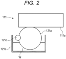
- Fig. 2 is a schematic sectional view of a first cleaning device.
- the image forming apparatus 100 includes a recording head 110 including a plurality of recording heads and a cleaning device 120 including a plurality of cleaning devices.
- the image forming apparatus 100 is an inkjet image forming apparatus, and discharges droplets while moving the recording head 110 relative to a recording medium in the main scanning direction (first direction) D1 and the sub-scanning direction (second direction) D2.
- the main scanning direction D1 is a direction orthogonal to the sub-scanning direction D2.
- the droplets form an image on the surface of the recording medium.
- the recording medium include recording media typically used for inkjet recording, such as paper, fabric, plastic films, and glass plates.
- the recording medium may be a sheet-shaped medium cut in a predetermined size, or may be a long medium that is wound like a roll and can be fed continuously.
- the image forming apparatus 100 may form an image on a recording medium with the recording head 110 fixed or with the recording medium fixed.
- the recording medium intermittently movable in the sub-scanning direction D2 by a conveying device (not illustrated), and the recording head 110 is movable in the main scanning direction D1.
- the cleaning device 120 is movable at least in the sub-scanning direction D2.
- the recording head 110 includes a first recording head 111 and a second recording head 112.
- the first recording head 111 and the second recording head 112 are mounted on a first carriage 114 movable on a first rail 113 bridged in the width direction of the recording medium.
- the first recording head 111 and the second recording head 112 reciprocate in the main scanning direction D1 as the first carriage 114 reciprocates in the main scanning direction D1.
- the first recording head 111 has a first discharge face 111a having a hole through which a first droplet is discharged.
- the first droplet is a so-called ink containing a resin.
- the number of first recording heads 111 is not particularly limited. The number of first recording heads 111 is appropriately set in response to the color type of the first droplet to be discharged. In the present embodiment, the number of first recording heads 111 is four.
- the first recording heads 111 each discharge the first droplet through the hole of the first discharge face 111a while moving in the main scanning direction D1, thereby recording a desired image onto the recording medium intermittently moved in the sub-scanning direction D2.
- the second recording head 112 has a second discharge face 112a having a hole through which a second droplet is discharged.
- the second droplet contains less resin than the resin contained in the first droplet.
- the second droplet preferably contains no resin.
- the second droplet is a flocculant for aggregating the first droplet or an overcoat liquid.
- the number of second recording heads 112 is not particularly limited. In the present embodiment, the number of second recording heads 112 is one.
- the second recording head 112 discharges the second droplet through the hole of the second discharge face 112a to the recording medium while moving in the main scanning direction D1.
- the first droplet Due to the discharge of the second droplet to the recording medium to which the first droplet has been discharged, the first droplet is aggregated by the second droplet to be fixed to the recording medium.
- the first droplet may be discharged immediately after the second droplet is discharged.
- the number of second recording heads 112 is two.
- the overcoat liquid may be discharged from the first recording head 111 in response to the amount of resin contained in the overcoat liquid.
- the array of the first recording heads 111 and the second recording head 112 on the first carriage 114 is not particularly limited.
- the recording head 110 includes the first recording head 111, the first recording head 111, the first recording head 111, and the second recording head 112 disposed in this order in view along the main scanning direction D1.
- the cleaning device 120 includes a first cleaning device 121 and a second cleaning device 122.
- the cleaning device 120 may be movable in the main scanning direction D1, may be movable in the sub-scanning direction D2, or may be fixed.
- the first cleaning device 121 and the second cleaning device 122 may be movable individually or simultaneously.
- the first cleaning device 121 and the second cleaning device 122 are mounted on a second carriage 124 movable on a second rail 123 disposed along the sub-scanning direction D2. Namely, the first cleaning device 121 and the second cleaning device 122 may be movable simultaneously.
- the first cleaning device 121 and the second cleaning device 122 reciprocate in the sub-scanning direction D2 as the second carriage 124 reciprocates in the sub-scanning direction D2.
- the first cleaning device 121 and the second cleaning device 122 are mounted on separate carriages (not illustrated).
- the first cleaning device 121 wipes a first droplet having adhered to the first discharge face 111a of each first recording head 111.
- the configuration of the first cleaning device 121 is not particularly limited as long as the above function can be exhibited.
- the first cleaning device 121 includes a first cleaning member 121a.
- the first cleaning device 121 in the present embodiment includes a container 121b with the cleaning liquid W stored therein and a squeeze member 121c in addition to the first cleaning member 121a.
- the first cleaning member 121a preferably has a surface layer formed of a moisture-absorbable elastic member, from the viewpoint of removing the first droplet.
- the first cleaning member 121a examples include a wet roller (sponge) and a wet web (nonwoven fabric). From the viewpoint of wiping the first discharge face 111a to which the first droplet containing resin has been adhered, the first cleaning member 121a is preferably a wet roller having a removing force (strong cleaning force) that increases depending on the rotational speed (the faster is stronger) and the rotational direction (the direction counter to the movement direction of the first cleaning device 121 is stronger).
- One first cleaning device 121 may be disposed for one first recording head 111, or one first cleaning device may be disposed for a plurality of first recording heads 111.
- the first cleaning device 121 is disposed for the four first recording heads 111. Namely, in the present embodiment, the first cleaning device 121 is provided so as to be able to collectively clean the four first recording heads 111.
- the first cleaning device 121 is movable in the sub-scanning direction D2.
- the first cleaning device 121 is disposed at a position different from a position corresponding to the first discharge faces 111a of the first recording heads 111. At the time of no image formation, the first cleaning device 121 moves to the position corresponding to the first discharge faces 111a of the first recording heads 111 to clean the first recording heads 111.
- Fig. 1A exemplarily illustrates the first cleaning device 121 disposed away from the first recording heads 111 in the conveyance direction (sub-scanning direction D2) of the recording medium.
- the first cleaning device 121 is connected to a first waste-liquid container 125.
- the first waste-liquid container 125 disposes the first waste liquid having been wiped by the first cleaning member 121a.
- the configuration of the first waste-liquid container 125 is not particularly limited as long as the above function can be exhibited.
- the first waste-liquid container 125 includes a first waste-liquid tank 125a, and a first connection passage 125b that connects the first cleaning device 121 and the first waste-liquid tank 125a.
- the second cleaning device 122 wipes the second droplet having adhered to the second discharge face 112a of the second recording head 112.
- the configuration of the second cleaning device 122 is not particularly limited as long as the above function can be exhibited.
- the second cleaning device 122 includes a second cleaning member 122a.
- Examples of the second cleaning member 122a include a dry blade (rubber member) and a dry web. From the viewpoint of wiping the second discharge face 112a to which the second droplet containing no resin has been adhered, the second cleaning member 122a is preferably a dry blade that reduces the head load and eliminates excessive maintenance.
- One second cleaning device 122 may be disposed for one second recording head 112, or one second cleaning device may be disposed for a plurality of second recording heads 112.
- the number of second recording heads 112 is one and the number of second cleaning devices 122 is one.
- the second cleaning device 122 is movable in the sub-scanning direction D2. At the time of image formation, the second cleaning device 122 is disposed at a position (standby position) different from a position corresponding to the second discharge face 112a of the second recording head 112. At the time of no image formation, the second cleaning device 122 moves to the position corresponding to the second discharge face 112a of the second recording head 112 to clean the second recording head 112.
- Fig. 1A exemplarily illustrates the second cleaning device 122 disposed away from the second recording head 112 in the conveyance direction (sub-scanning direction D2) of the recording medium.
- the second cleaning device 122 may be movable in the height direction D3 orthogonal to the main scanning direction D1 and the sub-scanning direction D2. In the present embodiment, the second cleaning device 122 is movable in the sub-scanning direction D2 and the height direction D3.
- the second cleaning device 122 is connected to a second waste-liquid container 126.
- the second waste-liquid container 126 disposes the second waste liquid having been wiped by the second cleaning member 122a.
- the configuration of the second waste-liquid container 126 is not particularly limited as long as the above function can be exhibited.
- the second waste-liquid container 126 includes a second waste-liquid tank 126a and a second connection passage 126b that connects the second cleaning device 122 and the second waste-liquid tank 126a.
- the cleaning force of the first cleaning device 121 to such a first recording head 111 as described above is preferably stronger than the cleaning force of the second cleaning device 122 to the second recording head 112.
- the first cleaning device 121 wipes the first droplet containing the resin
- the second cleaning device 122 wipes the second droplet containing no resin.
- the recording head 110 is not excessively maintained, so that the discharge face of the recording head 112 is not excessively worn.
- Fig. 3 is a block diagram illustrating the main functional configuration of the image forming apparatus 100.
- the image forming apparatus 100 includes a controller 150, a recording head driver 151, an input/output interface 152, a cleaning device driver 153, and a detector 154.
- the controller 150 includes a central processing unit (CPU) 150a, a random access memory (RAM) 150b, a read only memory (ROM) 150c, and a storage 150d.
- CPU central processing unit
- RAM random access memory
- ROM read only memory
- the CPU 150a reads various control programs and setting data stored in the ROM 150c, stores the programs and the setting data in the RAM 150b, and executes the programs to perform various types of arithmetic processing. Further, the CPU 150a centrally controls the entire operation of the image forming apparatus 100.
- the RAM 150b provides the CPU 150a with a working memory space and stores temporary data.
- the RAM 150b may include a non-volatile memory.
- the ROM 150c stores, for example, the various control programs executed by the CPU 150a and the setting data.
- a rewritable non-volatile memory such as an electrically erasable programmable read only memory (EEPROM) or a flash memory may be used.
- EEPROM electrically erasable programmable read only memory
- flash memory may be used.
- the storage 150d stores a print job (image recording command) input from an external device 155 through the input/output interface 152, and image data related to the print job and cleaning data.
- a hard disk drive (HDD) may be used, or a dynamic random access memory (DRAM) may be used in combination.
- DRAM dynamic random access memory
- the recording head driver 151 supplies a drive signal corresponding to image data to such a first recording head 111 as described above and the second recording head 112 at suitable timing, thereby causing each nozzle of the first recording head 111 and the second recording head 112 to discharge the first droplet and the second droplet in an amount corresponding to the pixel value of the image data.
- the input/output interface 152 mediates transmission and reception of data between the external device 155 and the controller 150.
- the input/output interface 152 includes, for example, any of various serial interfaces and various parallel interfaces, or a combination thereof.
- the external device 155 is, for example, a personal computer, and supplies an image recording command (print job), image data, and the like to the controller 150 through the input/output interface 152.
- the cleaning device driver 153 causes the first cleaning device 121 and the second cleaning device 122 to move, at suitable timing, according to the cleaning data stored in the storage 150d to clean the first recording heads 111 and the second recording head 112.
- the detector 154 detects the position of the first carriage 114 and detects the number of times of cleaning of the cleaning device 120.
- the detector 154 includes, for example, various sensors.
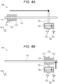
- FIG. 4A and 4B explanatorily illustrate the cleaning operation.
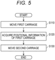
- Fig. 5 is a flowchart illustrates the cleaning operation.
- the first carriage 114 (such first recording heads 111 as described above and the second recording head 112) is movable in the main scanning direction D1
- a recording medium and the second carriage 124 (the first cleaning device 121 and the second cleaning device 122) are movable in the sub-scanning direction D2.
- the image forming method with the image forming apparatus 100 includes discharging droplets, with the first recording heads 111 and the second recording head 112 moving relative to the recording medium in the main scanning direction D1 and the sub-scanning direction D2, to form an image; wiping, by the first cleaning device 121, the first discharge faces 111a to clean the first recording heads 111; and wiping, by the second cleaning device 122, the second discharge face 112a to clean the second recording head 112.
- first droplets are discharged from the first recording heads 111 and second droplets are discharged from the second recording head 112 to form an image onto the recording medium.
- first droplets are mixed with the second droplets and aggregated on the recording medium.
- the recording medium is moved in the sub-scanning direction D2
- first carriage 114 scans in the main scanning direction D1 (backward operation)
- first droplets are discharged from the first recording heads 111 and second droplets are discharged from the second recording head 112 to form an image on the recording medium.
- the recording medium is moved in the sub-scanning direction D2. Repetition of this operation results in image formation with the first droplets and the second droplets on the recording medium.
- the recording head 110 is cleaned before image formation is performed or when no image formation is performed after image formation.
- the controller 150 causes the first carriage 114 to move a position where cleaning is to be performed (S110). As a result, the first recording heads 111 and the second recording head 112 move to a position where the cleaning is to be performed. Next, the controller 150 causes the detector 154 to acquire positional information of the first carriage 114 (S 120).
- the controller 150 having detected that the first carriage 114 is disposed at the position where the cleaning is to be performed causes the second carriage 124 to move in the sub-scanning direction D2 (forward operation) (S130).
- the first cleaning member (wet roller) 121a of the first cleaning device 121 wipes the first discharge faces 111a of the first recording heads 111
- the second cleaning member (dry blade) 122a of the second cleaning device 122 wipes the second discharge face 112a of the second recording head 112.
- the timing at which the first cleaning device 121 wipes the first recording heads 111 is the same as the timing at which the second cleaning device 122 wipes the second recording head 112. In such a manner, because the first recording heads 111 are wiped by the dedicated first cleaning device 121 and the second recording head 112 is wiped by the dedicated second cleaning device 122, excessive maintenance is not performed.
- the controller 150 causes the second carriage 124 to move in the sub-scanning direction D2 (backward operation).
- the second carriage 124 may reciprocate a plurality of times in the sub-scanning direction D2. As a result, even in a case where the first droplets having firmly adhered to the first discharge faces 111a, the first discharge faces 111a can be wiped.
- the timing at which the first cleaning device 121 cleans the first recording heads 111 may be different from the timing at which the second cleaning device 122 cleans the second recording head 112.
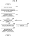
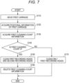
- Figs. 6 and 7 are explanatory flowcharts each illustrating the timing at which the first cleaning device 121 cleans the first recording heads 111 is different from the timing at which the second cleaning device 122 cleans the second recording head 112.
- the controller 150 causes the first carriage 114 to move (S110), acquires positional information of the first carriage 114 having moved (S120), and then acquires information regarding a difference in the number of times of cleaning (S130). Then, the controller 150 detects whether or not the difference in the number of times of cleaning is 3 (S140). If the difference in the number of times of cleaning is 3, the first recording heads 111 and the second recording head 112 are cleaned (S150). After the cleaning of the first recording heads 111 and the second recording head 112, the information regarding the difference in the number of times of cleaning is deleted (S160). If the difference in number of times of cleaning is less than 3, the first recording heads 111 are cleaned (S170).
- the controller 150 causes the second carriage 124 to move in the sub-scanning direction D2
- the second cleaning device 122 is retracted in the height direction D3 so as not to come into contact with the second recording head 112.
- the second cleaning device 122 moves in the height direction D3, so that the wiping timing can be adjusted even if the first cleaning device 121 and the second cleaning device 122 move simultaneously.
- first cleaning-count information may be acquired to adjust the timing of cleaning.
- the controller 150 causes the first carriage 114 to move (S110), acquires positional information of the first carriage 114 having moved (S120), and then acquires the first cleaning-count information (S135).
- the first cleaning-count information is the number of times of cleaning of the first recording heads 111 performed by the first cleaning device 121. Then, the controller 150 detects whether or not the first cleaning count is 3 (S145). If the first cleaning count is 3, the first recording heads 111 and the second recording head 112 are cleaned (S150). After the cleaning of the first recording heads 111 and the second recording head 112, the first cleaning-count information is deleted (S165).
- the first recording heads 111 are cleaned (S170).
- the controller 150 causes the second carriage 124 to move in the sub-scanning direction D2
- the second cleaning device 122 is retracted in the height direction D3 so as not to come into contact with the second recording head 112.
- the second cleaning device 122 moves in the height direction D3, so that the wiping timing can be adjusted even if the first cleaning device 121 and the second cleaning device 122 move simultaneously.
- the difference in the number of times of cleaning can be appropriately changed to an optimum difference according to, for example, the size of the image forming apparatus 100, or the type of the first droplet and the second droplet.
- whether to wipe the first recording heads 111 or to wipe both the first recording heads 111 and the second recording head 112 is set on the basis of the number of times of cleaning.
- the setting may not be set on the basis of the number of times of cleaning.
- it may be set on the basis of the storage amounts of the first waste-liquid tank 125a and the second waste-liquid tank 126a.
- the first waste-liquid tank 125a and the second waste-liquid tank 126a each include a liquid-level detection sensor (not illustrated) that detects the liquid level.
- each of the first cleaning device 121 and the second cleaning device 122 may be forcibly driven.
- the first recording heads 111 are cleaned by the first cleaning device 121 and the second recording head 112 is cleaned by the second cleaning device 122, so that the maintenance cost can be reduced without excessive maintenance.
- the image forming apparatus 200 of the present embodiment includes a recording head 110 on a first carriage 214.
- the recording head 110 on the first carriage 214 is different in disposition from the recording head 110 on the first carriage 114 of the image forming apparatus 100 of the first embodiment.
- the components of the image forming apparatus 200 similar to those of the image forming apparatus 100 of the first embodiment are denoted with the same reference signs, and thus the description thereof will not be given.
- Figs. 8A to 8C explanatorily illustrate a cleaning operation of the image forming apparatus 200 according to the second embodiment.
- Fig. 9 is a flowchart illustrating the cleaning operation of the image forming apparatus 200 according to the second embodiment.
- Figs. 8A to 8C illustrate the first carriage 214 and a second carriage 124.
- the image forming apparatus 200 in the present embodiment includes a first recording head 111, a second recording head 112, a first cleaning device 121, and a second cleaning device 122.
- the first recording head 111 and the second recording head 112 are mounted on the first carriage 214.
- the first cleaning device 121 and the second cleaning device 122 are mounted on the second carriage 124.
- a plurality of first recording heads 111 and one second recording head 112 are arrayed in the main scanning direction D1, and a plurality of arrays (two arrays in the present embodiment) are disposed in the sub-scanning direction D2.
- the two recording-head arrays have a difference in position in the main scanning direction D1.
- the first cleaning device 121 can clean three first recording heads 111, and the second cleaning device 122 can clean one second recording head 112.
- the first cleaning device 121 in the present embodiment cannot clean the entire of the recording head 110 in one cleaning operation (forward operation or backward operation).
- a controller 150 causes the first carriage 214 to move to a position where cleaning is to be performed (S110), and acquires positional information of the first carriage 214 having moved (S120). Thereafter, the controller 150 causes the second carriage 124 to move in the sub-scanning direction D2 (forward operation: upward in the figure) (S130), and the first recording heads 111 and the second recording head 112 are cleaned.
- the controller 150 causes the first carriage 214 to move in the main scanning direction D1 (S170). At this time, the controller 150 causes the first carriage 214 to move such that an uncleaned first recording head 111 is cleaned by the second cleaning device 122.
- the controller 150 causes the second carriage 124 to move in the sub-scanning direction D2 (backward operation: downward in the figure) (S180).
- the second cleaning device 122 is retracted in the height direction D3 so as not to come into contact with the first recording heads 111.
- the first cleaning device 121 cleans the uncleaned first recording head 111.
- the controller 150 determines whether cleaning has been repeated predetermined number of times (S190). If the entire of the recording head 110 is already cleaned, the cleaning operation ends (S190; Yes). If the entire of the recording head 110 is not yet cleaned, the controller 150 causes the first carriage 214 to move in the main scanning direction D1 (S200), and step S130 to step S190 are repeated.
- the movement of the first carriage 214 in the main scanning direction D1 (rightward in the figure) and the movement of the second carriage 124 in the sub-scanning direction D2 (upward and downward in the figure) are repeated, so that the entire of the recording head 110 can be cleaned.
- the controller 150 After the cleaning of the entire of the recording head 110 is completed, the controller 150 causes the second cleaning device 122 to move to its original position.
- the image forming apparatus 200 of the present embodiment has effects similar to those of the image forming apparatus 100 of the first embodiment.
- the image forming apparatus 300 of the present embodiment includes a recording head 110 on a first carriage 314.
- the recording head 110 on the first carriage 314 of the third embodiment are different in disposition from the recording head 110 on the first carriage 114 of the image forming apparatus 100 of the first embodiment.
- a cleaning device 120 on a second carriage 324 of the third embodiment is different in disposition from the cleaning device 120 on the second carriage 124 of the first embodiment.
- the components of the image forming apparatus 300 similar to those of the image forming apparatus 100 of the first embodiment are denoted with the same reference signs, and thus the description thereof will not be given.
- Fig. 10 illustrates the configuration of the image forming apparatus 300 according to the third embodiment.
- the image forming apparatus 300 in the present embodiment includes a first recording head 111, a second recording head 112, a first cleaning device 121, and a second cleaning device 122.
- the first recording head 111 and the second recording head 112 are mounted on the first carriage 314.
- the first cleaning device 121 and the second cleaning device 122 are mounted on the second carriage 324.
- a plurality of (eight) first recording heads 111 and two second recording heads 112 are arrayed in the main scanning direction D1. More specifically, one of the two second recording heads 112 is disposed adjacent to the leftmost first recording head 111 of the plurality of (eight) first recording heads 111, and the other one of the two second recording heads 112 is disposed adjacent to the rightmost first recording head 111 of the plurality of (eight) first recording heads 111. That is, the plurality of (eight) first recording heads 111 is interposed between the two second recording heads 112.
- one first cleaning device 121 and two second cleaning devices 122 are mounted on the second carriage 324. More specifically, one of the second cleaning devices 122 is disposed at one end of the first cleaning device 121 and the other one of the second cleaning devices 122 is disposed at the other end of the first cleaning device 121. Namely, the one first cleaning device 121 is interposed between the two second cleaning devices 122.
- a controller 150 causes the first carriage 314 to move to a position where cleaning is to be performed (S110), and acquires positional information of the first carriage 314 having moved (S120). Thereafter, the controller 150 causes the second carriage 324 to move in the sub-scanning direction D2 (forward operation: upward in the figure) (S130), and the first recording heads 111 and the second recording heads 112 are cleaned.
- the image forming apparatus 300 of the present embodiment has effects similar to those of the image forming apparatus 100 of the first embodiment.
- the image forming apparatus 400 of the present embodiment includes a recording head 110 on a first carriage 114.
- the recording head 110 on the first carriage 114 is different in disposition from the recording head 110 on the first carriage 114 of the image forming apparatus 100 of the first embodiment.
- the components of the image forming apparatus 400 similar to those of the image forming apparatus 100 of the first embodiment are denoted with the same reference signs, and thus the description thereof will not be given.
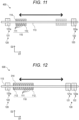
- Fig. 11 explanatorily illustrates a cleaning operation of the image forming apparatus 400 of the fourth embodiment.
- the image forming apparatus 400 in the present embodiment includes a first recording head 111, a second recording head 112, a first cleaning device 121, and a second cleaning device 122.
- the first recording head 111 and the second recording head 112 are mounted on the first carriage 114, and the first cleaning device 121 and the second cleaning device 122 are fixed.
- first carriage 114 on the first carriage 114, a plurality of (four) first recording heads 111 and one second recording head 112 are arrayed in the main scanning direction D1.
- the first carriage 114 is preferably movable to the outside of an area for image formation on a recording medium by the recording head 110.
- the first cleaning device 121 is disposed at one end outside the recording medium in the main scanning direction D1
- the second cleaning device 122 is disposed at the other end outside the recording medium in the main scanning direction D1.
- the first cleaning device 121 and the second cleaning device 122 are preferably disposed outside the area for image formation on the recording medium by the recording head 110. With this arrangement, cleaning is performed outside the area for image formation. Thus, the area for image formation is not contaminated in the case of a cleaning failure.
- the first cleaning device 121 can clean all the first recording heads 111 by one movement, and the number of second cleaning devices 122 is one.
- a controller 150 causes the first carriage 114 to move in the main scanning direction D1 (leftward in the figure) to clean the first recording heads 111 by the first cleaning device 121, and causes the first carriage 114 to move in the main scanning direction D1 (rightward in the figure) to clean the second recording head 112 by the second cleaning device 122.
- the image forming apparatus 400 of the present embodiment has effects similar to those of the image forming apparatus 100 of the first embodiment.
- the first cleaning device 121 and the second cleaning device 122 are fixed.
- the manufacturing cost can be reduced as compared with the image forming apparatus 100 of the first embodiment.
- Fig. 12 explanatory illustrates a cleaning operation of an image forming apparatus 500 of a fifth embodiment.
- the image forming apparatus 500 in the present embodiment includes a first recording head 111, a second recording head 112, a first cleaning device 121, and a second cleaning device 122.
- the first recording head 111 and the second recording head 112 are mounted on a first carriage 314, and the first cleaning device 121 and the second cleaning device 122 are fixed.
- first carriage 3114 on the first carriage 314, a plurality of (eight) first recording heads 111 and two second recording heads 112 are arrayed in the main scanning direction D1.
- the first carriage 314 is preferably movable to the outside of an area for image formation on a recording medium by the recording head 110.
- the first cleaning device 121 is disposed at one end outside the recording medium in the main scanning direction D1, and the second cleaning device 122 is disposed at the other end outside the recording medium in the main scanning direction D1.
- the first cleaning device 121 is movable in the height direction D3.
- the first cleaning device 121 and the second cleaning device 122 are preferably disposed outside the area for image formation on the recording medium by the recording head 110. With this arrangement, cleaning is performed outside the area for image formation. Thus, the area for image formation is not contaminated in the case of a cleaning failure.
- a controller 150 causes the first carriage 314 to move in the main scanning direction D1 (rightward in the figure). At this time, the first cleaning device 121 remains retracted so as not to come into contact with the second recording heads 112 in the height direction D3. After the second recording head 112 passes, the first cleaning device 121 moves to a position where the first cleaning device 121 comes into contact with the second recording head 112. Then, the first cleaning device 121 cleans the first recording heads 111, and the second cleaning device 122 cleans the second recording heads 112.
- the controller 150 causes the first carriage 314 to move in the main scanning direction D1 (leftward in the drawing). Then, the first cleaning device 121 cleans the first recording heads 111, and the second cleaning device 122 cleans the second recording heads 112.
- the image forming apparatus 500 of the present embodiment has effects similar to those of the image forming apparatus 100 of the first embodiment.
- the first cleaning device 121 is movable in the height direction D3 and the second cleaning device 122 is fixed.
- the manufacturing cost can be reduced as compared with the image forming apparatus 100 of the first embodiment.
- the image forming apparatuses and the image forming methods according to the above embodiments enable reduction in maintenance cost without excessive maintenance. Therefore, according to the above embodiments, it is expected to spread an image forming apparatus and an image forming method that have low maintenance cost and good image quality of an image to be formed.
- an image forming apparatus and an image forming method that enable maintaining long-duration cleaning performance.
Landscapes
- Ink Jet (AREA)
Abstract
Description
- The present invention relates to an image forming apparatus and an image forming method.
- Conventionally, as an inkjet image forming apparatus with an ink containing a binder resin, has been known an apparatus that forms an image by flocculating an ink and a flocculant not containing a binder resin as a pretreatment liquid on the surface of a recording medium in order to prevent penetration of the ink into the recording medium. An ink head for such an image formation has an ink discharge face and an ink adheres thereto, so that the adhered ink is cleaned periodically (for example, see
JP 7-214784 A JP 2005-225203 A - An inkjet recording apparatus including a cleaning device with a cleaning blade is disclosed in
JP 7-214784 A - A cleaning device that cleans a plurality of droplet discharge heads (recording heads) is disclosed in
JP 2005-225203 A JP 7-214784 A - In order to enhance adhesion to a recording medium, such an image forming apparatuses as described in
JP 7-214784 A JP 2005-225203 A - If the image forming apparatus in
JP 7-214784 A - In addition, such a cleaning device with a cleaning roller and a cleaning blade as described in the
JP 2005-225203 - An object of the present invention is to provide an image forming apparatus and an image forming method that enable reduction in maintenance cost without excessive maintenance.
- To achieve the abovementioned object, according to an aspect of the present invention, an image forming apparatus that discharges droplets, while moving a recording head relative to a recording medium in a main scanning direction and a sub-scanning direction, to form an image, reflecting one aspect of the present invention comprises: a carriage; a first recording head that has a first discharge face having a hole, that is disposed on the carriage, that discharges a first droplet containing resin through the hole, and that is included in the recording head; a second recording head that has a second discharge face having a hole, that is disposed on the carriage, that discharges, through the hole, a second droplet containing resin less than the resin contained in the first droplet, and that is included in the recording head; a first cleaning device that wipes the first discharge face to clean the first recording head; and a second cleaning device that is different from the first cleaning device and that wipes the second discharge face to clean the second recording head.
- The advantages and features provided by one or more embodiments of the invention will become more fully understood from the detailed description given hereinbelow and the appended drawings which are given by way of illustration only, and thus are not intended as a definition of the limits of the present invention:
-
Figs. 1A and 1B illustrate the configuration of an image forming apparatus according to a first embodiment of the present invention; -
Fig. 2 is a schematic sectional view of a first cleaning device; -
Fig. 3 is a block diagram illustrating the main part of a control system according to the present embodiment; -
Figs. 4A and 4B explanatorily illustrate a cleaning operation of the image forming apparatus according to the first embodiment; -
Fig. 5 is a flowchart illustrates the cleaning operation of the image forming apparatus according to the first embodiment; -
Fig. 6 is an explanatory flowchart illustrating a cleaning operation different in cleaning timing; -
Fig. 7 is another explanatory flowchart illustrating a cleaning operation different in cleaning timing; -
Figs. 8A to 8C explanatorily illustrate a cleaning operation of an image forming apparatus according to a second embodiment; -
Fig. 9 is a flowchart illustrating the cleaning operation of the image forming apparatus according to the second embodiment; -
Fig. 10 illustrates the configuration of an image forming apparatus according to a third embodiment; -
Fig. 11 illustrates the configuration of an image forming apparatus according to a fourth embodiment; and -
Fig. 12 illustrates the configuration of an image forming apparatus according a fifth embodiment. - Hereinafter, respective image forming apparatuses according to one or more embodiments of the present invention will be described with reference to the drawings. However, the scope of the invention is not limited to the disclosed embodiments.
-
Figs. 1A and 1B illustrates the configuration of animage forming apparatus 100 according to a first embodiment of the present invention.Fig. 1A is a plan view of theimage forming apparatus 100, andFig. 1B is a side view thereof.Fig. 2 is a schematic sectional view of a first cleaning device. - As illustrated in
Figs. 1A and 1B , theimage forming apparatus 100 includes arecording head 110 including a plurality of recording heads and acleaning device 120 including a plurality of cleaning devices. In the present embodiment, theimage forming apparatus 100 is an inkjet image forming apparatus, and discharges droplets while moving therecording head 110 relative to a recording medium in the main scanning direction (first direction) D1 and the sub-scanning direction (second direction) D2. In the present embodiment, the main scanning direction D1 is a direction orthogonal to the sub-scanning direction D2. - The droplets form an image on the surface of the recording medium. Examples of the recording medium include recording media typically used for inkjet recording, such as paper, fabric, plastic films, and glass plates. The recording medium may be a sheet-shaped medium cut in a predetermined size, or may be a long medium that is wound like a roll and can be fed continuously.
- The
image forming apparatus 100 may form an image on a recording medium with therecording head 110 fixed or with the recording medium fixed. In the present embodiment, the recording medium intermittently movable in the sub-scanning direction D2 by a conveying device (not illustrated), and therecording head 110 is movable in the main scanning direction D1. In the present embodiment, thecleaning device 120 is movable at least in the sub-scanning direction D2. - The
recording head 110 includes afirst recording head 111 and asecond recording head 112. Thefirst recording head 111 and thesecond recording head 112 are mounted on afirst carriage 114 movable on afirst rail 113 bridged in the width direction of the recording medium. Thefirst recording head 111 and thesecond recording head 112 reciprocate in the main scanning direction D1 as thefirst carriage 114 reciprocates in the main scanning direction D1. - The
first recording head 111 has afirst discharge face 111a having a hole through which a first droplet is discharged. The first droplet is a so-called ink containing a resin. The number offirst recording heads 111 is not particularly limited. The number offirst recording heads 111 is appropriately set in response to the color type of the first droplet to be discharged. In the present embodiment, the number offirst recording heads 111 is four. Thefirst recording heads 111 each discharge the first droplet through the hole of thefirst discharge face 111a while moving in the main scanning direction D1, thereby recording a desired image onto the recording medium intermittently moved in the sub-scanning direction D2. - The
second recording head 112 has asecond discharge face 112a having a hole through which a second droplet is discharged. The second droplet contains less resin than the resin contained in the first droplet. The second droplet preferably contains no resin. In the present embodiment, the second droplet is a flocculant for aggregating the first droplet or an overcoat liquid. The number of second recording heads 112 is not particularly limited. In the present embodiment, the number of second recording heads 112 is one. Thesecond recording head 112 discharges the second droplet through the hole of thesecond discharge face 112a to the recording medium while moving in the main scanning direction D1. Due to the discharge of the second droplet to the recording medium to which the first droplet has been discharged, the first droplet is aggregated by the second droplet to be fixed to the recording medium. The first droplet may be discharged immediately after the second droplet is discharged. In a case where a flocculant and an overcoat liquid are each discharged from thesecond recording head 112, the number of second recording heads 112 is two. Alternatively, the overcoat liquid may be discharged from thefirst recording head 111 in response to the amount of resin contained in the overcoat liquid. - The array of the first recording heads 111 and the
second recording head 112 on thefirst carriage 114 is not particularly limited. In the present embodiment, therecording head 110 includes thefirst recording head 111, thefirst recording head 111, thefirst recording head 111, and thesecond recording head 112 disposed in this order in view along the main scanning direction D1. - The
cleaning device 120 includes afirst cleaning device 121 and asecond cleaning device 122. Thecleaning device 120 may be movable in the main scanning direction D1, may be movable in the sub-scanning direction D2, or may be fixed. Thefirst cleaning device 121 and thesecond cleaning device 122 may be movable individually or simultaneously. In the present embodiment, thefirst cleaning device 121 and thesecond cleaning device 122 are mounted on asecond carriage 124 movable on asecond rail 123 disposed along the sub-scanning direction D2. Namely, thefirst cleaning device 121 and thesecond cleaning device 122 may be movable simultaneously. Thefirst cleaning device 121 and thesecond cleaning device 122 reciprocate in the sub-scanning direction D2 as thesecond carriage 124 reciprocates in the sub-scanning direction D2. In a case where thefirst cleaning device 121 and thesecond cleaning device 122 are movable individually, thefirst cleaning device 121 and thesecond cleaning device 122 are mounted on separate carriages (not illustrated). - The
first cleaning device 121 wipes a first droplet having adhered to thefirst discharge face 111a of eachfirst recording head 111. The configuration of thefirst cleaning device 121 is not particularly limited as long as the above function can be exhibited. Thefirst cleaning device 121 includes afirst cleaning member 121a. As illustrated inFig. 2 , thefirst cleaning device 121 in the present embodiment includes acontainer 121b with the cleaning liquid W stored therein and asqueeze member 121c in addition to thefirst cleaning member 121a. Thefirst cleaning member 121a preferably has a surface layer formed of a moisture-absorbable elastic member, from the viewpoint of removing the first droplet. Examples of thefirst cleaning member 121a include a wet roller (sponge) and a wet web (nonwoven fabric). From the viewpoint of wiping thefirst discharge face 111a to which the first droplet containing resin has been adhered, thefirst cleaning member 121a is preferably a wet roller having a removing force (strong cleaning force) that increases depending on the rotational speed (the faster is stronger) and the rotational direction (the direction counter to the movement direction of thefirst cleaning device 121 is stronger). - One
first cleaning device 121 may be disposed for onefirst recording head 111, or one first cleaning device may be disposed for a plurality of first recording heads 111. In the present embodiment, thefirst cleaning device 121 is disposed for the four first recording heads 111. Namely, in the present embodiment, thefirst cleaning device 121 is provided so as to be able to collectively clean the four first recording heads 111. - In the present embodiment, the
first cleaning device 121 is movable in the sub-scanning direction D2. - At the time of image formation, the
first cleaning device 121 is disposed at a position different from a position corresponding to the first discharge faces 111a of the first recording heads 111. At the time of no image formation, thefirst cleaning device 121 moves to the position corresponding to the first discharge faces 111a of the first recording heads 111 to clean the first recording heads 111.Fig. 1A exemplarily illustrates thefirst cleaning device 121 disposed away from the first recording heads 111 in the conveyance direction (sub-scanning direction D2) of the recording medium. - The
first cleaning device 121 is connected to a first waste-liquid container 125. The first waste-liquid container 125 disposes the first waste liquid having been wiped by thefirst cleaning member 121a. The configuration of the first waste-liquid container 125 is not particularly limited as long as the above function can be exhibited. In the present embodiment, the first waste-liquid container 125 includes a first waste-liquid tank 125a, and afirst connection passage 125b that connects thefirst cleaning device 121 and the first waste-liquid tank 125a. - The
second cleaning device 122 wipes the second droplet having adhered to thesecond discharge face 112a of thesecond recording head 112. The configuration of thesecond cleaning device 122 is not particularly limited as long as the above function can be exhibited. Thesecond cleaning device 122 includes asecond cleaning member 122a. Examples of thesecond cleaning member 122a include a dry blade (rubber member) and a dry web. From the viewpoint of wiping thesecond discharge face 112a to which the second droplet containing no resin has been adhered, thesecond cleaning member 122a is preferably a dry blade that reduces the head load and eliminates excessive maintenance. - One
second cleaning device 122 may be disposed for onesecond recording head 112, or one second cleaning device may be disposed for a plurality of second recording heads 112. In the present embodiment, the number of second recording heads 112 is one and the number ofsecond cleaning devices 122 is one. - In the present embodiment, the
second cleaning device 122 is movable in the sub-scanning direction D2. At the time of image formation, thesecond cleaning device 122 is disposed at a position (standby position) different from a position corresponding to thesecond discharge face 112a of thesecond recording head 112. At the time of no image formation, thesecond cleaning device 122 moves to the position corresponding to thesecond discharge face 112a of thesecond recording head 112 to clean thesecond recording head 112.Fig. 1A exemplarily illustrates thesecond cleaning device 122 disposed away from thesecond recording head 112 in the conveyance direction (sub-scanning direction D2) of the recording medium. Thesecond cleaning device 122 may be movable in the height direction D3 orthogonal to the main scanning direction D1 and the sub-scanning direction D2. In the present embodiment, thesecond cleaning device 122 is movable in the sub-scanning direction D2 and the height direction D3. - The
second cleaning device 122 is connected to a second waste-liquid container 126. The second waste-liquid container 126 disposes the second waste liquid having been wiped by thesecond cleaning member 122a. The configuration of the second waste-liquid container 126 is not particularly limited as long as the above function can be exhibited. In the present embodiment, the second waste-liquid container 126 includes a second waste-liquid tank 126a and asecond connection passage 126b that connects thesecond cleaning device 122 and the second waste-liquid tank 126a. - The cleaning force of the
first cleaning device 121 to such afirst recording head 111 as described above is preferably stronger than the cleaning force of thesecond cleaning device 122 to thesecond recording head 112. As described above, thefirst cleaning device 121 wipes the first droplet containing the resin, and thesecond cleaning device 122 wipes the second droplet containing no resin. Thus, therecording head 110 is not excessively maintained, so that the discharge face of therecording head 112 is not excessively worn. -
Fig. 3 is a block diagram illustrating the main functional configuration of theimage forming apparatus 100. Theimage forming apparatus 100 includes acontroller 150, arecording head driver 151, an input/output interface 152, acleaning device driver 153, and adetector 154. - The
controller 150 includes a central processing unit (CPU) 150a, a random access memory (RAM) 150b, a read only memory (ROM) 150c, and astorage 150d. - The
CPU 150a reads various control programs and setting data stored in theROM 150c, stores the programs and the setting data in theRAM 150b, and executes the programs to perform various types of arithmetic processing. Further, theCPU 150a centrally controls the entire operation of theimage forming apparatus 100. - The
RAM 150b provides theCPU 150a with a working memory space and stores temporary data. TheRAM 150b may include a non-volatile memory. - The
ROM 150c stores, for example, the various control programs executed by theCPU 150a and the setting data. Instead of theROM 150c, a rewritable non-volatile memory such as an electrically erasable programmable read only memory (EEPROM) or a flash memory may be used. - The
storage 150d stores a print job (image recording command) input from anexternal device 155 through the input/output interface 152, and image data related to the print job and cleaning data. As thestorage 150d, for example, a hard disk drive (HDD) may be used, or a dynamic random access memory (DRAM) may be used in combination. - Under the control of the
controller 150, therecording head driver 151 supplies a drive signal corresponding to image data to such afirst recording head 111 as described above and thesecond recording head 112 at suitable timing, thereby causing each nozzle of thefirst recording head 111 and thesecond recording head 112 to discharge the first droplet and the second droplet in an amount corresponding to the pixel value of the image data. - The input/
output interface 152 mediates transmission and reception of data between theexternal device 155 and thecontroller 150. The input/output interface 152 includes, for example, any of various serial interfaces and various parallel interfaces, or a combination thereof. - The
external device 155 is, for example, a personal computer, and supplies an image recording command (print job), image data, and the like to thecontroller 150 through the input/output interface 152. - Under the control of the
controller 150, thecleaning device driver 153 causes thefirst cleaning device 121 and thesecond cleaning device 122 to move, at suitable timing, according to the cleaning data stored in thestorage 150d to clean the first recording heads 111 and thesecond recording head 112. - The
detector 154 detects the position of thefirst carriage 114 and detects the number of times of cleaning of thecleaning device 120. Thedetector 154 includes, for example, various sensors. - Next, an image forming method and a cleaning operation with the
image forming apparatus 100 will be described.Figs. 4A and 4B explanatorily illustrate the cleaning operation.Fig. 5 is a flowchart illustrates the cleaning operation. - Here, in the
image forming apparatus 100, the first carriage 114 (such first recording heads 111 as described above and the second recording head 112) is movable in the main scanning direction D1, and a recording medium and the second carriage 124 (thefirst cleaning device 121 and the second cleaning device 122) are movable in the sub-scanning direction D2. - The image forming method with the
image forming apparatus 100 includes discharging droplets, with the first recording heads 111 and thesecond recording head 112 moving relative to the recording medium in the main scanning direction D1 and the sub-scanning direction D2, to form an image; wiping, by thefirst cleaning device 121, the first discharge faces 111a to clean the first recording heads 111; and wiping, by thesecond cleaning device 122, thesecond discharge face 112a to clean thesecond recording head 112. - In the image formation, while the
first carriage 114 scans in the main scanning direction (forward operation), first droplets are discharged from the first recording heads 111 and second droplets are discharged from thesecond recording head 112 to form an image onto the recording medium. At this time, because the first droplets are discharged immediately after the second droplets are discharged, the first droplets are mixed with the second droplets and aggregated on the recording medium. After the recording medium is moved in the sub-scanning direction D2, while thefirst carriage 114 scans in the main scanning direction D1 (backward operation), first droplets are discharged from the first recording heads 111 and second droplets are discharged from thesecond recording head 112 to form an image on the recording medium. Then, the recording medium is moved in the sub-scanning direction D2. Repetition of this operation results in image formation with the first droplets and the second droplets on the recording medium. - The
recording head 110 is cleaned before image formation is performed or when no image formation is performed after image formation. - As illustrated in
Figs. 4A and5 , thecontroller 150 causes thefirst carriage 114 to move a position where cleaning is to be performed (S110). As a result, the first recording heads 111 and thesecond recording head 112 move to a position where the cleaning is to be performed. Next, thecontroller 150 causes thedetector 154 to acquire positional information of the first carriage 114 (S 120). - Then, as illustrated in
Figs. 4B and5 , thecontroller 150 having detected that thefirst carriage 114 is disposed at the position where the cleaning is to be performed causes thesecond carriage 124 to move in the sub-scanning direction D2 (forward operation) (S130). As a result, the first cleaning member (wet roller) 121a of thefirst cleaning device 121 wipes the first discharge faces 111a of the first recording heads 111, and the second cleaning member (dry blade) 122a of thesecond cleaning device 122 wipes thesecond discharge face 112a of thesecond recording head 112. In the present embodiment, the timing at which thefirst cleaning device 121 wipes the first recording heads 111 is the same as the timing at which thesecond cleaning device 122 wipes thesecond recording head 112. In such a manner, because the first recording heads 111 are wiped by the dedicatedfirst cleaning device 121 and thesecond recording head 112 is wiped by the dedicatedsecond cleaning device 122, excessive maintenance is not performed. - Then, the
controller 150 causes thesecond carriage 124 to move in the sub-scanning direction D2 (backward operation). - The
second carriage 124 may reciprocate a plurality of times in the sub-scanning direction D2. As a result, even in a case where the first droplets having firmly adhered to the first discharge faces 111a, the first discharge faces 111a can be wiped. - The timing at which the
first cleaning device 121 cleans the first recording heads 111 may be different from the timing at which thesecond cleaning device 122 cleans thesecond recording head 112. -
Figs. 6 and7 are explanatory flowcharts each illustrating the timing at which thefirst cleaning device 121 cleans the first recording heads 111 is different from the timing at which thesecond cleaning device 122 cleans thesecond recording head 112. - As illustrated in
Fig. 6 , thecontroller 150 causes thefirst carriage 114 to move (S110), acquires positional information of thefirst carriage 114 having moved (S120), and then acquires information regarding a difference in the number of times of cleaning (S130). Then, thecontroller 150 detects whether or not the difference in the number of times of cleaning is 3 (S140). If the difference in the number of times of cleaning is 3, the first recording heads 111 and thesecond recording head 112 are cleaned (S150). After the cleaning of the first recording heads 111 and thesecond recording head 112, the information regarding the difference in the number of times of cleaning is deleted (S160). If the difference in number of times of cleaning is less than 3, the first recording heads 111 are cleaned (S170). Specifically, when thecontroller 150 causes thesecond carriage 124 to move in the sub-scanning direction D2, thesecond cleaning device 122 is retracted in the height direction D3 so as not to come into contact with thesecond recording head 112. In such a manner, thesecond cleaning device 122 moves in the height direction D3, so that the wiping timing can be adjusted even if thefirst cleaning device 121 and thesecond cleaning device 122 move simultaneously. - Alternatively, first cleaning-count information may be acquired to adjust the timing of cleaning. As illustrated in
Fig. 7 , thecontroller 150 causes thefirst carriage 114 to move (S110), acquires positional information of thefirst carriage 114 having moved (S120), and then acquires the first cleaning-count information (S135). The first cleaning-count information is the number of times of cleaning of the first recording heads 111 performed by thefirst cleaning device 121. Then, thecontroller 150 detects whether or not the first cleaning count is 3 (S145). If the first cleaning count is 3, the first recording heads 111 and thesecond recording head 112 are cleaned (S150). After the cleaning of the first recording heads 111 and thesecond recording head 112, the first cleaning-count information is deleted (S165). If the first cleaning count is less than 3, the first recording heads 111 are cleaned (S170). Specifically, when thecontroller 150 causes thesecond carriage 124 to move in the sub-scanning direction D2, thesecond cleaning device 122 is retracted in the height direction D3 so as not to come into contact with thesecond recording head 112. In such a manner, thesecond cleaning device 122 moves in the height direction D3, so that the wiping timing can be adjusted even if thefirst cleaning device 121 and thesecond cleaning device 122 move simultaneously. - The difference in the number of times of cleaning can be appropriately changed to an optimum difference according to, for example, the size of the
image forming apparatus 100, or the type of the first droplet and the second droplet. Here, whether to wipe the first recording heads 111 or to wipe both the first recording heads 111 and thesecond recording head 112 is set on the basis of the number of times of cleaning. However, the setting may not be set on the basis of the number of times of cleaning. For example, it may be set on the basis of the storage amounts of the first waste-liquid tank 125a and the second waste-liquid tank 126a. In this case, the first waste-liquid tank 125a and the second waste-liquid tank 126a each include a liquid-level detection sensor (not illustrated) that detects the liquid level. Further, each of thefirst cleaning device 121 and thesecond cleaning device 122 may be forcibly driven. - As described above, according to the
image forming apparatus 100 of the present embodiment, the first recording heads 111 are cleaned by thefirst cleaning device 121 and thesecond recording head 112 is cleaned by thesecond cleaning device 122, so that the maintenance cost can be reduced without excessive maintenance. - Next, an
image forming apparatus 200 according to a second embodiment will be described. Theimage forming apparatus 200 of the present embodiment includes arecording head 110 on afirst carriage 214. Therecording head 110 on thefirst carriage 214 is different in disposition from therecording head 110 on thefirst carriage 114 of theimage forming apparatus 100 of the first embodiment. The components of theimage forming apparatus 200 similar to those of theimage forming apparatus 100 of the first embodiment are denoted with the same reference signs, and thus the description thereof will not be given. -
Figs. 8A to 8C explanatorily illustrate a cleaning operation of theimage forming apparatus 200 according to the second embodiment.Fig. 9 is a flowchart illustrating the cleaning operation of theimage forming apparatus 200 according to the second embodiment.Figs. 8A to 8C illustrate thefirst carriage 214 and asecond carriage 124. - As illustrated in
Figs. 8A to 8C , theimage forming apparatus 200 in the present embodiment includes afirst recording head 111, asecond recording head 112, afirst cleaning device 121, and asecond cleaning device 122. Thefirst recording head 111 and thesecond recording head 112 are mounted on thefirst carriage 214. Thefirst cleaning device 121 and thesecond cleaning device 122 are mounted on thesecond carriage 124. - In the present embodiment, a plurality of first recording heads 111 and one
second recording head 112 are arrayed in the main scanning direction D1, and a plurality of arrays (two arrays in the present embodiment) are disposed in the sub-scanning direction D2. The two recording-head arrays have a difference in position in the main scanning direction D1. - The
first cleaning device 121 can clean three first recording heads 111, and thesecond cleaning device 122 can clean onesecond recording head 112. Thefirst cleaning device 121 in the present embodiment cannot clean the entire of therecording head 110 in one cleaning operation (forward operation or backward operation). - As illustrated in
Figs. 8A and9 , acontroller 150 causes thefirst carriage 214 to move to a position where cleaning is to be performed (S110), and acquires positional information of thefirst carriage 214 having moved (S120). Thereafter, thecontroller 150 causes thesecond carriage 124 to move in the sub-scanning direction D2 (forward operation: upward in the figure) (S130), and the first recording heads 111 and thesecond recording head 112 are cleaned. - As illustrated in
Figs. 8B and9 , thecontroller 150 causes thefirst carriage 214 to move in the main scanning direction D1 (S170). At this time, thecontroller 150 causes thefirst carriage 214 to move such that an uncleanedfirst recording head 111 is cleaned by thesecond cleaning device 122. - As illustrated in
Figs. 8C and9 , thecontroller 150 causes thesecond carriage 124 to move in the sub-scanning direction D2 (backward operation: downward in the figure) (S180). At this time, because there is nosecond recording head 112 to be cleaned, thesecond cleaning device 122 is retracted in the height direction D3 so as not to come into contact with the first recording heads 111. As a result, thefirst cleaning device 121 cleans the uncleanedfirst recording head 111. - Then, the
controller 150 determines whether cleaning has been repeated predetermined number of times (S190). If the entire of therecording head 110 is already cleaned, the cleaning operation ends (S190; Yes). If the entire of therecording head 110 is not yet cleaned, thecontroller 150 causes thefirst carriage 214 to move in the main scanning direction D1 (S200), and step S130 to step S190 are repeated. - In such a manner, according to the
image forming apparatus 200 of the present embodiment, the movement of thefirst carriage 214 in the main scanning direction D1 (rightward in the figure) and the movement of thesecond carriage 124 in the sub-scanning direction D2 (upward and downward in the figure) are repeated, so that the entire of therecording head 110 can be cleaned. - After the cleaning of the entire of the
recording head 110 is completed, thecontroller 150 causes thesecond cleaning device 122 to move to its original position. - As described above, the
image forming apparatus 200 of the present embodiment has effects similar to those of theimage forming apparatus 100 of the first embodiment. - Next, an
image forming apparatus 300 according to a third embodiment will be described. Theimage forming apparatus 300 of the present embodiment includes arecording head 110 on afirst carriage 314. Therecording head 110 on thefirst carriage 314 of the third embodiment are different in disposition from therecording head 110 on thefirst carriage 114 of theimage forming apparatus 100 of the first embodiment. Acleaning device 120 on asecond carriage 324 of the third embodiment is different in disposition from thecleaning device 120 on thesecond carriage 124 of the first embodiment. The components of theimage forming apparatus 300 similar to those of theimage forming apparatus 100 of the first embodiment are denoted with the same reference signs, and thus the description thereof will not be given. -
Fig. 10 illustrates the configuration of theimage forming apparatus 300 according to the third embodiment. - As illustrated in
Fig. 10 , theimage forming apparatus 300 in the present embodiment includes afirst recording head 111, asecond recording head 112, afirst cleaning device 121, and asecond cleaning device 122. Thefirst recording head 111 and thesecond recording head 112 are mounted on thefirst carriage 314. Thefirst cleaning device 121 and thesecond cleaning device 122 are mounted on thesecond carriage 324. - In the present embodiment, on the
first carriage 314, a plurality of (eight) first recording heads 111 and two second recording heads 112 are arrayed in the main scanning direction D1. More specifically, one of the two second recording heads 112 is disposed adjacent to the leftmostfirst recording head 111 of the plurality of (eight) first recording heads 111, and the other one of the two second recording heads 112 is disposed adjacent to the rightmostfirst recording head 111 of the plurality of (eight) first recording heads 111. That is, the plurality of (eight) first recording heads 111 is interposed between the two second recording heads 112. - In the present embodiment, one
first cleaning device 121 and twosecond cleaning devices 122 are mounted on thesecond carriage 324. More specifically, one of thesecond cleaning devices 122 is disposed at one end of thefirst cleaning device 121 and the other one of thesecond cleaning devices 122 is disposed at the other end of thefirst cleaning device 121. Namely, the onefirst cleaning device 121 is interposed between the twosecond cleaning devices 122. - In this case, a
controller 150 causes thefirst carriage 314 to move to a position where cleaning is to be performed (S110), and acquires positional information of thefirst carriage 314 having moved (S120). Thereafter, thecontroller 150 causes thesecond carriage 324 to move in the sub-scanning direction D2 (forward operation: upward in the figure) (S130), and the first recording heads 111 and the second recording heads 112 are cleaned. - As described above, the
image forming apparatus 300 of the present embodiment has effects similar to those of theimage forming apparatus 100 of the first embodiment. - Next, an
image forming apparatus 400 according to a fourth embodiment will be described. Theimage forming apparatus 400 of the present embodiment includes arecording head 110 on afirst carriage 114. Therecording head 110 on thefirst carriage 114 is different in disposition from therecording head 110 on thefirst carriage 114 of theimage forming apparatus 100 of the first embodiment. The components of theimage forming apparatus 400 similar to those of theimage forming apparatus 100 of the first embodiment are denoted with the same reference signs, and thus the description thereof will not be given. -
Fig. 11 explanatorily illustrates a cleaning operation of theimage forming apparatus 400 of the fourth embodiment. - As illustrated in
Fig. 11 , theimage forming apparatus 400 in the present embodiment includes afirst recording head 111, asecond recording head 112, afirst cleaning device 121, and asecond cleaning device 122. Thefirst recording head 111 and thesecond recording head 112 are mounted on thefirst carriage 114, and thefirst cleaning device 121 and thesecond cleaning device 122 are fixed. - In the present embodiment, on the
first carriage 114, a plurality of (four) first recording heads 111 and onesecond recording head 112 are arrayed in the main scanning direction D1. Thefirst carriage 114 is preferably movable to the outside of an area for image formation on a recording medium by therecording head 110. - In the present embodiment, the
first cleaning device 121 is disposed at one end outside the recording medium in the main scanning direction D1, and thesecond cleaning device 122 is disposed at the other end outside the recording medium in the main scanning direction D1. Thefirst cleaning device 121 and thesecond cleaning device 122 are preferably disposed outside the area for image formation on the recording medium by therecording head 110. With this arrangement, cleaning is performed outside the area for image formation. Thus, the area for image formation is not contaminated in the case of a cleaning failure. Thefirst cleaning device 121 can clean all the first recording heads 111 by one movement, and the number ofsecond cleaning devices 122 is one. - In this case, a
controller 150 causes thefirst carriage 114 to move in the main scanning direction D1 (leftward in the figure) to clean the first recording heads 111 by thefirst cleaning device 121, and causes thefirst carriage 114 to move in the main scanning direction D1 (rightward in the figure) to clean thesecond recording head 112 by thesecond cleaning device 122. - As described above, the
image forming apparatus 400 of the present embodiment has effects similar to those of theimage forming apparatus 100 of the first embodiment. In theimage forming apparatus 400 of the present embodiment, thefirst cleaning device 121 and thesecond cleaning device 122 are fixed. Thus, the manufacturing cost can be reduced as compared with theimage forming apparatus 100 of the first embodiment. -
Fig. 12 explanatory illustrates a cleaning operation of animage forming apparatus 500 of a fifth embodiment. - As illustrated in
Fig. 12 , theimage forming apparatus 500 in the present embodiment includes afirst recording head 111, asecond recording head 112, afirst cleaning device 121, and asecond cleaning device 122. Thefirst recording head 111 and thesecond recording head 112 are mounted on afirst carriage 314, and thefirst cleaning device 121 and thesecond cleaning device 122 are fixed. - In the present embodiment, on the
first carriage 314, a plurality of (eight) first recording heads 111 and two second recording heads 112 are arrayed in the main scanning direction D1. Thefirst carriage 314 is preferably movable to the outside of an area for image formation on a recording medium by therecording head 110. - In the present embodiment, the
first cleaning device 121 is disposed at one end outside the recording medium in the main scanning direction D1, and thesecond cleaning device 122 is disposed at the other end outside the recording medium in the main scanning direction D1. Thefirst cleaning device 121 is movable in the height direction D3. Thefirst cleaning device 121 and thesecond cleaning device 122 are preferably disposed outside the area for image formation on the recording medium by therecording head 110. With this arrangement, cleaning is performed outside the area for image formation. Thus, the area for image formation is not contaminated in the case of a cleaning failure. - In this case, a
controller 150 causes thefirst carriage 314 to move in the main scanning direction D1 (rightward in the figure). At this time, thefirst cleaning device 121 remains retracted so as not to come into contact with the second recording heads 112 in the height direction D3. After thesecond recording head 112 passes, thefirst cleaning device 121 moves to a position where thefirst cleaning device 121 comes into contact with thesecond recording head 112. Then, thefirst cleaning device 121 cleans the first recording heads 111, and thesecond cleaning device 122 cleans the second recording heads 112. - Further, the
controller 150 causes thefirst carriage 314 to move in the main scanning direction D1 (leftward in the drawing). Then, thefirst cleaning device 121 cleans the first recording heads 111, and thesecond cleaning device 122 cleans the second recording heads 112. - As described above, the
image forming apparatus 500 of the present embodiment has effects similar to those of theimage forming apparatus 100 of the first embodiment. In theimage forming apparatus 500 of the present embodiment, thefirst cleaning device 121 is movable in the height direction D3 and thesecond cleaning device 122 is fixed. Thus, the manufacturing cost can be reduced as compared with theimage forming apparatus 100 of the first embodiment. - The image forming apparatuses and the image forming methods according to the above embodiments enable reduction in maintenance cost without excessive maintenance. Therefore, according to the above embodiments, it is expected to spread an image forming apparatus and an image forming method that have low maintenance cost and good image quality of an image to be formed.
- According to embodiments of the present invention, provided can be an image forming apparatus and an image forming method that enable maintaining long-duration cleaning performance.
- Although embodiments of the present invention have been described and illustrated in detail, the disclosed embodiments are made for purposes of illustration and example only and not limitation. The scope of the present invention should be interpreted by terms of the appended claims.
- Note that the present technology may be configured as described below.
- (1) An image forming apparatus that discharges droplets, while moving a recording head relative to a recording medium in a main scanning direction and a sub-scanning direction, to form an image, the image forming apparatus comprising:
- a carriage;
- a first recording head that has a first discharge face having a hole, that is disposed on the carriage, that discharges a first droplet containing resin through the hole, and that is included in the recording head;
- a second recording head that has a second discharge face having a hole, that is disposed on the carriage, that discharges, through the hole, a second droplet containing resin less than the resin contained in the first droplet, and that is included in the recording head;
- a first cleaning device that wipes the first discharge face to clean the first recording head; and
- a second cleaning device that is different from the first cleaning device and that wipes the second discharge face to clean the second recording head.
- (2) The image forming apparatus according to (1), wherein the second droplet contains no resin.
- (3) The image forming apparatus according to (1), wherein a cleaning force of the first cleaning device to the first recording head is stronger than a cleaning force of the second cleaning device to the second recording head.
- (4) The image forming apparatus according to (1), wherein
- the first cleaning device includes a wet roller, and
- the second cleaning device includes a dry blade.
- (5) The image forming apparatus according to (1), wherein
- the first cleaning device is movable to the first recording head, and
- the second cleaning device is movable to the second recording head.
- (6) The image forming apparatus according to (1), wherein the first cleaning device cleans the first recording head immediately before or immediately after movement of the first recording head in the main scanning direction, and the second cleaning device cleans the second recording head immediately before or after movement of the second recording head in the main scanning direction.
- (7) The image forming apparatus according to (1), wherein
- the first cleaning device and the second cleaning device are movable integrally together, and
- in a case where the first cleaning device cleans the first discharge face of the first recording head, the second cleaning device is spaced apart from the second discharge face of the second recording head.
- (8) The image forming apparatus according to (1), wherein the first cleaning device and the second cleaning device are movable individually or simultaneously.
- (9) The image forming apparatus according to (1), wherein
- the first cleaning device is disposed at one end outside the recording medium in the main scanning direction, and
- the second cleaning device is disposed at another end outside the recording medium in the main scanning direction.
- (10) The image forming apparatus according to (1), wherein a number of times of cleaning of the first recording head performed by the first cleaning device is larger than a number of times of cleaning of the second recording head performed by the second cleaning device.
- (11) The image forming apparatus according to (1), wherein timing at which the second cleaning device cleans the second recording head is different from timing at which the first cleaning device cleans the first recording head.
- (12) The image forming apparatus according to (1), wherein
- the first cleaning device is connected to a first waste-liquid container for disposal of a first waste liquid having been wiped, and
- the second cleaning device is connected to a second waste-liquid container for disposal of a second waste liquid having been wiped.
- (13) An image forming method with the image forming apparatus according to (1) for image formation onto a recording medium, the image forming method comprising:
- discharging droplets, with the first recording head and the second recording head moving relative to the recording medium in the main scanning direction and the sub-scanning direction, to form an image;
- cleaning the first recording head by wiping, with the first cleaning device, the first discharge face; and
- cleaning the second recording head by wiping, with the second cleaning device, the second discharge face.
- (14) The image forming method according to (13), wherein a cleaning force of the first cleaning device to the first recording head in the cleaning the first recording head is stronger than a cleaning force of the second cleaning device to the second recording head in the cleaning the second recording head.
- (15) The image forming method according to (13), wherein
- the cleaning the first recording head includes cleaning, by the first cleaning device, the first recording head immediately before or immediately after main scanning, and
- the cleaning the second recording head includes cleaning, by the second cleaning device, the second recording head immediately before or immediately after main scanning.
- (16) The image forming method according to (13), wherein
- the first cleaning device and the second cleaning device are movable integrally together, and
- in the cleaning the first recording head, the second cleaning device is spaced apart from the second discharge face of the second recording head.
- (17) The image forming method according to (13), wherein
- the first cleaning device is disposed at one end outside the recording medium in the main scanning direction,
- the second cleaning device is disposed at another end outside the recording medium in the main scanning direction,
- the cleaning the first recording head includes cleaning, by the first cleaning device, the first recording head immediately before or immediately after main scanning, and
- the cleaning the second recording head includes cleaning, by the second cleaning device, the second recording head immediately before or immediately after main scanning.
- (18) The image forming method according to (13), wherein a number of times of cleaning the first recording head is larger than a number of times of the cleaning the second recording head.
- (19) The image forming method according to (13), wherein the cleaning the first recording head and the cleaning the second recording head are mutually different in timing.
Claims (15)
- An image forming apparatus (100, 200, 300, 400, 500) that discharges droplets, while moving a recording head (110) relative to a recording medium in a main scanning direction (D1) and a sub-scanning direction (D2), to form an image, the image forming apparatus (100, 200, 300, 400, 500) comprising:a carriage (114, 124, 214, 314, 324);a first recording head (111) that has a first discharge face (111a) having a hole, that is disposed on the carriage (114, 124, 214, 314, 324), that discharges a first droplet containing resin through the hole, and that is included in the recording head (110);a second recording head (112) that has a second discharge face (112a) having a hole, that is disposed on the carriage (114, 124, 214, 314, 324), that discharges, through the hole, a second droplet containing resin less than the resin contained in the first droplet, and that is included in the recording head (110);a first cleaning device (121) that wipes the first discharge face (111a) to clean the first recording head (111); anda second cleaning device (122) that is different from the first cleaning device (121) and that wipes the second discharge face (112a) to clean the second recording head (112).
- The image forming apparatus (100, 200, 300, 400, 500) according to claim 1, wherein the second droplet contains no resin.
- The image forming apparatus (100, 200, 300, 400, 500) according to claim 1, wherein a cleaning force of the first cleaning device (121) to the first recording head (111) is stronger than a cleaning force of the second cleaning device (122) to the second recording head (112).
- The image forming apparatus (100, 200, 300, 400, 500) according to claim 1, whereinthe first cleaning device (121) includes a wet roller, andthe second cleaning device (122) includes a dry blade.
- The image forming apparatus (100, 200, 300, 400, 500) according to claim 1, whereinthe first cleaning device (121) is movable to the first recording head (111), andthe second cleaning device (122) is movable to the second recording head (112).
- The image forming apparatus (100, 200, 300, 400, 500) according to claim 1, wherein the first cleaning device (121) cleans the first recording head (111) immediately before or immediately after movement of the first recording head (111) in the main scanning direction (D1), and the second cleaning device (122) cleans the second recording head (112) immediately before or after movement of the second recording head (112) in the main scanning direction (D1).
- The image forming apparatus (100, 200, 300, 400, 500) according to claim 1, wherein
the first cleaning device (121) and the second cleaning device (122) are movable integrally together, and in a case where the first cleaning device (121) cleans the first discharge face (111a) of the first recording head (111), the second cleaning device (122) is spaced apart from the second discharge face (112a) of the second recording head (112). - The image forming apparatus (100, 200, 300, 400, 500) according to claim 1, wherein the first cleaning device (121) and the second cleaning device (122) are movable individually or simultaneously.
- The image forming apparatus (100, 200, 300, 400, 500) according to claim 1, whereinthe first cleaning device (121) is disposed at one end outside the recording medium in the main scanning direction (D1), andthe second cleaning device (122) is disposed at another end outside the recording medium in the main scanning direction (D1); orwherein a number of times of cleaning of the first recording head (111) performed by the first cleaning device (121) is larger than a number of times of cleaning of the second recording head (112) performed by the second cleaning device (122); orwherein timing at which the second cleaning device (122) cleans the second recording head (112) is different from timing at which the first cleaning device (121) cleans the first recording head (111); orwhereinthe first cleaning device (121) is connected to a first waste-liquid container (125) for disposal of a first waste liquid having been wiped, andthe second cleaning device (122) is connected to a second waste-liquid container (126) for disposal of a second waste liquid having been wiped.
- An image forming method with the image forming apparatus (100, 200, 300, 400, 500) according to claim 1 for image formation onto a recording medium, the image forming method comprising:discharging droplets, with the first recording head (111) and the second recording head (112) moving relative to the recording medium in the main scanning direction (D1) and the sub-scanning direction (D2), to form an image;cleaning the first recording head (111) by wiping, with the first cleaning device (121), the first discharge face (111a); andcleaning the second recording head (112) by wiping, with the second cleaning device (122), the second discharge face (112a).
- The image forming method according to claim 10, wherein a cleaning force of the first cleaning device (121) to the first recording head (111) in the cleaning the first recording head (111) is stronger than a cleaning force of the second cleaning device (122) to the second recording head (112) in the cleaning the second recording head (112).
- The image forming method according to claim 10, whereinthe cleaning the first recording head (111) includes cleaning, by the first cleaning device (121), the first recording head (111) immediately before or immediately after main scanning, andthe cleaning the second recording head (112) includes cleaning, by the second cleaning device (122), the second recording head (112) immediately before or immediately after main scanning.
- The image forming method according to claim 10, wherein
the first cleaning device (121) and the second cleaning device (122) are movable integrally together, and in the cleaning the first recording head (111), the second cleaning device (122) is spaced apart from the second discharge face (112a) of the second recording head (112). - The image forming method according to claim 10, whereinthe first cleaning device (121) is disposed at one end outside the recording medium in the main scanning direction (D1),the second cleaning device (122) is disposed at another end outside the recording medium in the main scanning direction (D1),the cleaning the first recording head (111) includes cleaning, by the first cleaning device (121), the first recording head (111) immediately before or immediately after main scanning, andthe cleaning the second recording head (112) includes cleaning, by the second cleaning device (122), the second recording head (112) immediately before or immediately after main scanning.
- The image forming method according to claim 10, wherein a number of times of cleaning the first recording head (111) is larger than a number of times of the cleaning the second recording head (112); or
wherein the cleaning the first recording head (111) and the cleaning the second recording head (112) are mutually different in timing.
Applications Claiming Priority (1)
| Application Number | Priority Date | Filing Date | Title |
|---|---|---|---|
| JP2022148431A JP2024043313A (en) | 2022-09-16 | 2022-09-16 | Image forming apparatus and image forming method |
Publications (2)
| Publication Number | Publication Date |
|---|---|
| EP4338965A1 true EP4338965A1 (en) | 2024-03-20 |
| EP4338965B1 EP4338965B1 (en) | 2025-07-30 |
Family
ID=88020811
Family Applications (1)
| Application Number | Title | Priority Date | Filing Date |
|---|---|---|---|
| EP23196827.2A Active EP4338965B1 (en) | 2022-09-16 | 2023-09-12 | Image forming apparatus and image forming method |
Country Status (3)
| Country | Link |
|---|---|
| US (1) | US12472745B2 (en) |
| EP (1) | EP4338965B1 (en) |
| JP (1) | JP2024043313A (en) |
Families Citing this family (1)
| Publication number | Priority date | Publication date | Assignee | Title |
|---|---|---|---|---|
| JP2026000071A (en) * | 2024-06-17 | 2026-01-05 | コニカミノルタ株式会社 | Image forming apparatus, control method and program for image forming apparatus |
Citations (5)
| Publication number | Priority date | Publication date | Assignee | Title |
|---|---|---|---|---|
| JPH07214784A (en) | 1994-02-03 | 1995-08-15 | Fuji Xerox Co Ltd | Ink jet recording apparatus |
| EP0841168B1 (en) * | 1996-11-06 | 2003-08-06 | Canon Kabushiki Kaisha | Liquid discharging apparatus and cleaning system for the same |
| JP2005225203A (en) | 2004-02-16 | 2005-08-25 | Sony Corp | Liquid discharge head cleaning device and liquid discharge device |
| US20080238984A1 (en) * | 2007-03-29 | 2008-10-02 | Yasuko Yahiro | Inkjet recording apparatus and method |
| JP2012232424A (en) * | 2011-04-28 | 2012-11-29 | Konica Minolta Ij Technologies Inc | Inkjet recording device and maintenance method |
Family Cites Families (3)
| Publication number | Priority date | Publication date | Assignee | Title |
|---|---|---|---|---|
| JP3177128B2 (en) * | 1994-08-10 | 2001-06-18 | キヤノン株式会社 | Discharge unit, ink jet cartridge using discharge unit, ink jet printing apparatus and method |
| US6460967B1 (en) * | 1998-03-24 | 2002-10-08 | Konica Corporation | Liquid jetting apparatus |
| JP2007050591A (en) * | 2005-08-17 | 2007-03-01 | Sony Corp | Liquid discharge head cleaning device |
-
2022
- 2022-09-16 JP JP2022148431A patent/JP2024043313A/en active Pending
-
2023
- 2023-08-08 US US18/366,993 patent/US12472745B2/en active Active
- 2023-09-12 EP EP23196827.2A patent/EP4338965B1/en active Active
Patent Citations (5)
| Publication number | Priority date | Publication date | Assignee | Title |
|---|---|---|---|---|
| JPH07214784A (en) | 1994-02-03 | 1995-08-15 | Fuji Xerox Co Ltd | Ink jet recording apparatus |
| EP0841168B1 (en) * | 1996-11-06 | 2003-08-06 | Canon Kabushiki Kaisha | Liquid discharging apparatus and cleaning system for the same |
| JP2005225203A (en) | 2004-02-16 | 2005-08-25 | Sony Corp | Liquid discharge head cleaning device and liquid discharge device |
| US20080238984A1 (en) * | 2007-03-29 | 2008-10-02 | Yasuko Yahiro | Inkjet recording apparatus and method |
| JP2012232424A (en) * | 2011-04-28 | 2012-11-29 | Konica Minolta Ij Technologies Inc | Inkjet recording device and maintenance method |
Also Published As
| Publication number | Publication date |
|---|---|
| US12472745B2 (en) | 2025-11-18 |
| US20240092083A1 (en) | 2024-03-21 |
| JP2024043313A (en) | 2024-03-29 |
| EP4338965B1 (en) | 2025-07-30 |
Similar Documents
| Publication | Publication Date | Title |
|---|---|---|
| CN102673157B (en) | Fluid ejection device and flushing method | |
| JPH07246708A (en) | Inkjet recording device | |
| JP2008221534A (en) | Liquid discharge device and liquid discharge surface maintenance method | |
| EP3539782A1 (en) | Liquid discharging device and cleaning method | |
| JPH04320852A (en) | inkjet recording device | |
| EP2644385A1 (en) | Inkjet recording device and method for controlling the same | |
| JP4944631B2 (en) | Inkjet recording apparatus and recovery processing method | |
| EP4338965B1 (en) | Image forming apparatus and image forming method | |
| JP2022186388A (en) | Recording device and its control method | |
| US9266334B2 (en) | Inkjet recording apparatus and control method for the inkjet recording apparatus | |
| JP4979279B2 (en) | Ink jet recording apparatus and wiping operation control method | |
| US20140368577A1 (en) | Inkjet recording apparatus and control method for wiping unit | |
| US12447746B2 (en) | Recording apparatus, control method, and storage medium | |
| JP4507213B2 (en) | Liquid ejecting apparatus and image forming apparatus | |
| JP4258732B2 (en) | Image forming apparatus | |
| JP6525818B2 (en) | Liquid discharge device | |
| JP2021030482A (en) | Inkjet recording device | |
| JP2005007866A (en) | Inkjet head cleaning apparatus and inkjet recording apparatus | |
| JP6007624B2 (en) | Image forming apparatus | |
| US20150306880A1 (en) | Liquid ejection apparatus | |
| JP2009202337A (en) | Image formation device | |
| JP2006123539A (en) | Liquid ejection apparatus and ejection abnormality determination method | |
| JP4913525B2 (en) | Inkjet recording device | |
| JP2001219565A (en) | Ink jet recording device | |
| JP2016203383A (en) | Control device, control method, and control program |
Legal Events
| Date | Code | Title | Description |
|---|---|---|---|
| PUAI | Public reference made under article 153(3) epc to a published international application that has entered the european phase |
Free format text: ORIGINAL CODE: 0009012 |
|
| STAA | Information on the status of an ep patent application or granted ep patent |
Free format text: STATUS: THE APPLICATION HAS BEEN PUBLISHED |
|
| AK | Designated contracting states |
Kind code of ref document: A1 Designated state(s): AL AT BE BG CH CY CZ DE DK EE ES FI FR GB GR HR HU IE IS IT LI LT LU LV MC ME MK MT NL NO PL PT RO RS SE SI SK SM TR |
|
| P01 | Opt-out of the competence of the unified patent court (upc) registered |
Effective date: 20240326 |
|
| STAA | Information on the status of an ep patent application or granted ep patent |
Free format text: STATUS: REQUEST FOR EXAMINATION WAS MADE |
|
| 17P | Request for examination filed |
Effective date: 20240912 |
|
| RBV | Designated contracting states (corrected) |
Designated state(s): AL AT BE BG CH CY CZ DE DK EE ES FI FR GB GR HR HU IE IS IT LI LT LU LV MC ME MK MT NL NO PL PT RO RS SE SI SK SM TR |
|
| GRAP | Despatch of communication of intention to grant a patent |
Free format text: ORIGINAL CODE: EPIDOSNIGR1 |
|
| STAA | Information on the status of an ep patent application or granted ep patent |
Free format text: STATUS: GRANT OF PATENT IS INTENDED |
|
| RIC1 | Information provided on ipc code assigned before grant |
Ipc: C09D 11/00 20140101ALI20250320BHEP Ipc: B41J 2/21 20060101ALI20250320BHEP Ipc: B41J 2/165 20060101AFI20250320BHEP |
|
| INTG | Intention to grant announced |
Effective date: 20250404 |
|
| GRAS | Grant fee paid |
Free format text: ORIGINAL CODE: EPIDOSNIGR3 |
|
| GRAA | (expected) grant |
Free format text: ORIGINAL CODE: 0009210 |
|
| STAA | Information on the status of an ep patent application or granted ep patent |
Free format text: STATUS: THE PATENT HAS BEEN GRANTED |
|
| AK | Designated contracting states |
Kind code of ref document: B1 Designated state(s): AL AT BE BG CH CY CZ DE DK EE ES FI FR GB GR HR HU IE IS IT LI LT LU LV MC ME MK MT NL NO PL PT RO RS SE SI SK SM TR |
|
| REG | Reference to a national code |
Ref country code: GB Ref legal event code: FG4D |
|
| REG | Reference to a national code |
Ref country code: CH Ref legal event code: EP |
|
| REG | Reference to a national code |
Ref country code: DE Ref legal event code: R096 Ref document number: 602023005204 Country of ref document: DE |
|
| REG | Reference to a national code |
Ref country code: IE Ref legal event code: FG4D |
|
| PGFP | Annual fee paid to national office [announced via postgrant information from national office to epo] |
Ref country code: TR Payment date: 20250905 Year of fee payment: 3 |
|
| PGFP | Annual fee paid to national office [announced via postgrant information from national office to epo] |
Ref country code: FR Payment date: 20250821 Year of fee payment: 3 Ref country code: AT Payment date: 20251020 Year of fee payment: 3 |
|
| REG | Reference to a national code |
Ref country code: NL Ref legal event code: MP Effective date: 20250730 |
|
| REG | Reference to a national code |
Ref country code: AT Ref legal event code: MK05 Ref document number: 1818540 Country of ref document: AT Kind code of ref document: T Effective date: 20250730 |
|
| PG25 | Lapsed in a contracting state [announced via postgrant information from national office to epo] |
Ref country code: PT Free format text: LAPSE BECAUSE OF FAILURE TO SUBMIT A TRANSLATION OF THE DESCRIPTION OR TO PAY THE FEE WITHIN THE PRESCRIBED TIME-LIMIT Effective date: 20251202 |
|
| PG25 | Lapsed in a contracting state [announced via postgrant information from national office to epo] |
Ref country code: IS Free format text: LAPSE BECAUSE OF FAILURE TO SUBMIT A TRANSLATION OF THE DESCRIPTION OR TO PAY THE FEE WITHIN THE PRESCRIBED TIME-LIMIT Effective date: 20251130 |
|
| PG25 | Lapsed in a contracting state [announced via postgrant information from national office to epo] |
Ref country code: NO Free format text: LAPSE BECAUSE OF FAILURE TO SUBMIT A TRANSLATION OF THE DESCRIPTION OR TO PAY THE FEE WITHIN THE PRESCRIBED TIME-LIMIT Effective date: 20251030 |
|
| REG | Reference to a national code |
Ref country code: LT Ref legal event code: MG9D |
|
| PG25 | Lapsed in a contracting state [announced via postgrant information from national office to epo] |
Ref country code: AT Free format text: LAPSE BECAUSE OF FAILURE TO SUBMIT A TRANSLATION OF THE DESCRIPTION OR TO PAY THE FEE WITHIN THE PRESCRIBED TIME-LIMIT Effective date: 20250730 |
|
| PG25 | Lapsed in a contracting state [announced via postgrant information from national office to epo] |
Ref country code: FI Free format text: LAPSE BECAUSE OF FAILURE TO SUBMIT A TRANSLATION OF THE DESCRIPTION OR TO PAY THE FEE WITHIN THE PRESCRIBED TIME-LIMIT Effective date: 20250730 |
|
| PGFP | Annual fee paid to national office [announced via postgrant information from national office to epo] |
Ref country code: IT Payment date: 20250930 Year of fee payment: 3 |
|
| PG25 | Lapsed in a contracting state [announced via postgrant information from national office to epo] |
Ref country code: HR Free format text: LAPSE BECAUSE OF FAILURE TO SUBMIT A TRANSLATION OF THE DESCRIPTION OR TO PAY THE FEE WITHIN THE PRESCRIBED TIME-LIMIT Effective date: 20250730 Ref country code: NL Free format text: LAPSE BECAUSE OF FAILURE TO SUBMIT A TRANSLATION OF THE DESCRIPTION OR TO PAY THE FEE WITHIN THE PRESCRIBED TIME-LIMIT Effective date: 20250730 |
|
| PG25 | Lapsed in a contracting state [announced via postgrant information from national office to epo] |
Ref country code: GR Free format text: LAPSE BECAUSE OF FAILURE TO SUBMIT A TRANSLATION OF THE DESCRIPTION OR TO PAY THE FEE WITHIN THE PRESCRIBED TIME-LIMIT Effective date: 20251031 |
|
| PG25 | Lapsed in a contracting state [announced via postgrant information from national office to epo] |
Ref country code: SE Free format text: LAPSE BECAUSE OF FAILURE TO SUBMIT A TRANSLATION OF THE DESCRIPTION OR TO PAY THE FEE WITHIN THE PRESCRIBED TIME-LIMIT Effective date: 20250730 |
|
| PG25 | Lapsed in a contracting state [announced via postgrant information from national office to epo] |
Ref country code: LV Free format text: LAPSE BECAUSE OF FAILURE TO SUBMIT A TRANSLATION OF THE DESCRIPTION OR TO PAY THE FEE WITHIN THE PRESCRIBED TIME-LIMIT Effective date: 20250730 |
|
| PG25 | Lapsed in a contracting state [announced via postgrant information from national office to epo] |
Ref country code: PL Free format text: LAPSE BECAUSE OF FAILURE TO SUBMIT A TRANSLATION OF THE DESCRIPTION OR TO PAY THE FEE WITHIN THE PRESCRIBED TIME-LIMIT Effective date: 20250730 Ref country code: BG Free format text: LAPSE BECAUSE OF FAILURE TO SUBMIT A TRANSLATION OF THE DESCRIPTION OR TO PAY THE FEE WITHIN THE PRESCRIBED TIME-LIMIT Effective date: 20250730 |
|
| PG25 | Lapsed in a contracting state [announced via postgrant information from national office to epo] |
Ref country code: RS Free format text: LAPSE BECAUSE OF FAILURE TO SUBMIT A TRANSLATION OF THE DESCRIPTION OR TO PAY THE FEE WITHIN THE PRESCRIBED TIME-LIMIT Effective date: 20251030 |
|
| PG25 | Lapsed in a contracting state [announced via postgrant information from national office to epo] |
Ref country code: ES Free format text: LAPSE BECAUSE OF FAILURE TO SUBMIT A TRANSLATION OF THE DESCRIPTION OR TO PAY THE FEE WITHIN THE PRESCRIBED TIME-LIMIT Effective date: 20250730 |
|
| PG25 | Lapsed in a contracting state [announced via postgrant information from national office to epo] |
Ref country code: RO Free format text: LAPSE BECAUSE OF FAILURE TO SUBMIT A TRANSLATION OF THE DESCRIPTION OR TO PAY THE FEE WITHIN THE PRESCRIBED TIME-LIMIT Effective date: 20250730 |
|
| PG25 | Lapsed in a contracting state [announced via postgrant information from national office to epo] |
Ref country code: SM Free format text: LAPSE BECAUSE OF FAILURE TO SUBMIT A TRANSLATION OF THE DESCRIPTION OR TO PAY THE FEE WITHIN THE PRESCRIBED TIME-LIMIT Effective date: 20250730 |
|
| PG25 | Lapsed in a contracting state [announced via postgrant information from national office to epo] |
Ref country code: DK Free format text: LAPSE BECAUSE OF FAILURE TO SUBMIT A TRANSLATION OF THE DESCRIPTION OR TO PAY THE FEE WITHIN THE PRESCRIBED TIME-LIMIT Effective date: 20250730 |
|
| PG25 | Lapsed in a contracting state [announced via postgrant information from national office to epo] |
Ref country code: CZ Free format text: LAPSE BECAUSE OF FAILURE TO SUBMIT A TRANSLATION OF THE DESCRIPTION OR TO PAY THE FEE WITHIN THE PRESCRIBED TIME-LIMIT Effective date: 20250730 |
|
| PG25 | Lapsed in a contracting state [announced via postgrant information from national office to epo] |
Ref country code: EE Free format text: LAPSE BECAUSE OF FAILURE TO SUBMIT A TRANSLATION OF THE DESCRIPTION OR TO PAY THE FEE WITHIN THE PRESCRIBED TIME-LIMIT Effective date: 20250730 Ref country code: SK Free format text: LAPSE BECAUSE OF FAILURE TO SUBMIT A TRANSLATION OF THE DESCRIPTION OR TO PAY THE FEE WITHIN THE PRESCRIBED TIME-LIMIT Effective date: 20250730 |