EP4338958A1 - Panneaux de couverture de toit résistant aux déformations - Google Patents
Panneaux de couverture de toit résistant aux déformations Download PDFInfo
- Publication number
- EP4338958A1 EP4338958A1 EP23190704.9A EP23190704A EP4338958A1 EP 4338958 A1 EP4338958 A1 EP 4338958A1 EP 23190704 A EP23190704 A EP 23190704A EP 4338958 A1 EP4338958 A1 EP 4338958A1
- Authority
- EP
- European Patent Office
- Prior art keywords
- facer
- coverboard
- warp
- installation
- core layer
- Prior art date
- Legal status (The legal status is an assumption and is not a legal conclusion. Google has not performed a legal analysis and makes no representation as to the accuracy of the status listed.)
- Pending
Links
- 239000012792 core layer Substances 0.000 claims abstract description 58
- 238000009434 installation Methods 0.000 claims abstract description 54
- 238000000034 method Methods 0.000 claims abstract description 19
- 238000003825 pressing Methods 0.000 claims abstract description 7
- 229920003023 plastic Polymers 0.000 claims description 40
- 239000004033 plastic Substances 0.000 claims description 40
- 239000012634 fragment Substances 0.000 claims description 34
- 239000000853 adhesive Substances 0.000 claims description 28
- 230000001070 adhesive effect Effects 0.000 claims description 28
- 239000010410 layer Substances 0.000 claims description 25
- 229920001059 synthetic polymer Polymers 0.000 claims description 21
- 239000000203 mixture Substances 0.000 claims description 10
- 229920001169 thermoplastic Polymers 0.000 claims description 6
- 239000004416 thermosoftening plastic Substances 0.000 claims description 6
- 239000000123 paper Substances 0.000 description 36
- 239000000463 material Substances 0.000 description 21
- 239000012528 membrane Substances 0.000 description 21
- 239000003365 glass fiber Substances 0.000 description 17
- -1 polyethylene Polymers 0.000 description 16
- 239000002344 surface layer Substances 0.000 description 16
- 239000006260 foam Substances 0.000 description 14
- 239000011152 fibreglass Substances 0.000 description 13
- 239000004744 fabric Substances 0.000 description 10
- 239000002699 waste material Substances 0.000 description 10
- XLYOFNOQVPJJNP-UHFFFAOYSA-N water Substances O XLYOFNOQVPJJNP-UHFFFAOYSA-N 0.000 description 9
- 239000004698 Polyethylene Substances 0.000 description 8
- 229920000573 polyethylene Polymers 0.000 description 8
- 230000008901 benefit Effects 0.000 description 7
- 239000010440 gypsum Substances 0.000 description 6
- 229910052602 gypsum Inorganic materials 0.000 description 6
- 238000003801 milling Methods 0.000 description 6
- 239000004743 Polypropylene Substances 0.000 description 5
- 238000011900 installation process Methods 0.000 description 5
- 238000004519 manufacturing process Methods 0.000 description 5
- 229920000728 polyester Polymers 0.000 description 5
- 229920001155 polypropylene Polymers 0.000 description 5
- 239000004800 polyvinyl chloride Substances 0.000 description 5
- 230000001681 protective effect Effects 0.000 description 5
- 239000011347 resin Substances 0.000 description 5
- 229920005989 resin Polymers 0.000 description 5
- 229920001187 thermosetting polymer Polymers 0.000 description 5
- IRIAEXORFWYRCZ-UHFFFAOYSA-N Butylbenzyl phthalate Chemical compound CCCCOC(=O)C1=CC=CC=C1C(=O)OCC1=CC=CC=C1 IRIAEXORFWYRCZ-UHFFFAOYSA-N 0.000 description 4
- VGGSQFUCUMXWEO-UHFFFAOYSA-N Ethene Chemical compound C=C VGGSQFUCUMXWEO-UHFFFAOYSA-N 0.000 description 4
- 239000004677 Nylon Substances 0.000 description 4
- 229910010272 inorganic material Inorganic materials 0.000 description 4
- 239000011147 inorganic material Substances 0.000 description 4
- 230000001788 irregular Effects 0.000 description 4
- 229920001684 low density polyethylene Polymers 0.000 description 4
- 239000004702 low-density polyethylene Substances 0.000 description 4
- 229920001179 medium density polyethylene Polymers 0.000 description 4
- 239000004701 medium-density polyethylene Substances 0.000 description 4
- 229920001778 nylon Polymers 0.000 description 4
- 239000005022 packaging material Substances 0.000 description 4
- 238000004806 packaging method and process Methods 0.000 description 4
- 229920000642 polymer Polymers 0.000 description 4
- 229920000915 polyvinyl chloride Polymers 0.000 description 4
- 230000008569 process Effects 0.000 description 4
- 238000004064 recycling Methods 0.000 description 4
- 229920002397 thermoplastic olefin Polymers 0.000 description 4
- 239000002023 wood Substances 0.000 description 4
- 239000005977 Ethylene Substances 0.000 description 3
- 239000010426 asphalt Substances 0.000 description 3
- 238000010276 construction Methods 0.000 description 3
- 229920001971 elastomer Polymers 0.000 description 3
- 229920006284 nylon film Polymers 0.000 description 3
- 239000011120 plywood Substances 0.000 description 3
- 229920006267 polyester film Polymers 0.000 description 3
- 239000005060 rubber Substances 0.000 description 3
- BLDFSDCBQJUWFG-UHFFFAOYSA-N 2-(methylamino)-1,2-diphenylethanol Chemical compound C=1C=CC=CC=1C(NC)C(O)C1=CC=CC=C1 BLDFSDCBQJUWFG-UHFFFAOYSA-N 0.000 description 2
- 229920000178 Acrylic resin Polymers 0.000 description 2
- 239000004925 Acrylic resin Substances 0.000 description 2
- MQIUGAXCHLFZKX-UHFFFAOYSA-N Di-n-octyl phthalate Natural products CCCCCCCCOC(=O)C1=CC=CC=C1C(=O)OCCCCCCCC MQIUGAXCHLFZKX-UHFFFAOYSA-N 0.000 description 2
- 239000004793 Polystyrene Substances 0.000 description 2
- 239000011398 Portland cement Substances 0.000 description 2
- 229910000831 Steel Inorganic materials 0.000 description 2
- 239000000654 additive Substances 0.000 description 2
- XAGFODPZIPBFFR-UHFFFAOYSA-N aluminium Chemical compound [Al] XAGFODPZIPBFFR-UHFFFAOYSA-N 0.000 description 2
- 229910052782 aluminium Inorganic materials 0.000 description 2
- BJQHLKABXJIVAM-UHFFFAOYSA-N bis(2-ethylhexyl) phthalate Chemical compound CCCCC(CC)COC(=O)C1=CC=CC=C1C(=O)OCC(CC)CCCC BJQHLKABXJIVAM-UHFFFAOYSA-N 0.000 description 2
- 239000004568 cement Substances 0.000 description 2
- 239000003086 colorant Substances 0.000 description 2
- 239000004567 concrete Substances 0.000 description 2
- 229920001577 copolymer Polymers 0.000 description 2
- 239000004794 expanded polystyrene Substances 0.000 description 2
- 239000000835 fiber Substances 0.000 description 2
- 239000011094 fiberboard Substances 0.000 description 2
- 239000011888 foil Substances 0.000 description 2
- 239000013538 functional additive Substances 0.000 description 2
- 238000010438 heat treatment Methods 0.000 description 2
- 229920001903 high density polyethylene Polymers 0.000 description 2
- 239000004700 high-density polyethylene Substances 0.000 description 2
- 229920000092 linear low density polyethylene Polymers 0.000 description 2
- 239000004707 linear low-density polyethylene Substances 0.000 description 2
- 239000000395 magnesium oxide Substances 0.000 description 2
- CPLXHLVBOLITMK-UHFFFAOYSA-N magnesium oxide Inorganic materials [Mg]=O CPLXHLVBOLITMK-UHFFFAOYSA-N 0.000 description 2
- AXZKOIWUVFPNLO-UHFFFAOYSA-N magnesium;oxygen(2-) Chemical compound [O-2].[Mg+2] AXZKOIWUVFPNLO-UHFFFAOYSA-N 0.000 description 2
- 239000004014 plasticizer Substances 0.000 description 2
- 229920000582 polyisocyanurate Polymers 0.000 description 2
- 239000011495 polyisocyanurate Substances 0.000 description 2
- 229920002223 polystyrene Polymers 0.000 description 2
- 229920002635 polyurethane Polymers 0.000 description 2
- 239000004814 polyurethane Substances 0.000 description 2
- 238000001556 precipitation Methods 0.000 description 2
- 239000003755 preservative agent Substances 0.000 description 2
- QQONPFPTGQHPMA-UHFFFAOYSA-N propylene Natural products CC=C QQONPFPTGQHPMA-UHFFFAOYSA-N 0.000 description 2
- 125000004805 propylene group Chemical group [H]C([H])([H])C([H])([*:1])C([H])([H])[*:2] 0.000 description 2
- 239000003381 stabilizer Substances 0.000 description 2
- 239000010959 steel Substances 0.000 description 2
- 238000012876 topography Methods 0.000 description 2
- 229920002943 EPDM rubber Polymers 0.000 description 1
- 229920012485 Plasticized Polyvinyl chloride Polymers 0.000 description 1
- 229920005830 Polyurethane Foam Polymers 0.000 description 1
- NIXOWILDQLNWCW-UHFFFAOYSA-N acrylic acid group Chemical group C(C=C)(=O)O NIXOWILDQLNWCW-UHFFFAOYSA-N 0.000 description 1
- 230000002411 adverse Effects 0.000 description 1
- 230000000712 assembly Effects 0.000 description 1
- 238000000429 assembly Methods 0.000 description 1
- 230000004888 barrier function Effects 0.000 description 1
- 238000005452 bending Methods 0.000 description 1
- 239000011230 binding agent Substances 0.000 description 1
- 230000015572 biosynthetic process Effects 0.000 description 1
- 239000011248 coating agent Substances 0.000 description 1
- 238000000576 coating method Methods 0.000 description 1
- 239000002131 composite material Substances 0.000 description 1
- 230000001186 cumulative effect Effects 0.000 description 1
- 230000000694 effects Effects 0.000 description 1
- 230000006353 environmental stress Effects 0.000 description 1
- 239000011876 fused mixture Substances 0.000 description 1
- 239000011521 glass Substances 0.000 description 1
- 239000011256 inorganic filler Substances 0.000 description 1
- 229910003475 inorganic filler Inorganic materials 0.000 description 1
- 239000002655 kraft paper Substances 0.000 description 1
- KJLLKLRVCJAFRY-UHFFFAOYSA-N mebutizide Chemical compound ClC1=C(S(N)(=O)=O)C=C2S(=O)(=O)NC(C(C)C(C)CC)NC2=C1 KJLLKLRVCJAFRY-UHFFFAOYSA-N 0.000 description 1
- 238000002844 melting Methods 0.000 description 1
- 230000008018 melting Effects 0.000 description 1
- 238000012986 modification Methods 0.000 description 1
- 230000004048 modification Effects 0.000 description 1
- 239000003607 modifier Substances 0.000 description 1
- 229920000098 polyolefin Polymers 0.000 description 1
- 239000011496 polyurethane foam Substances 0.000 description 1
- 230000003014 reinforcing effect Effects 0.000 description 1
- 238000009436 residential construction Methods 0.000 description 1
- 239000011435 rock Substances 0.000 description 1
- 239000002904 solvent Substances 0.000 description 1
- 229920003051 synthetic elastomer Polymers 0.000 description 1
- 239000005061 synthetic rubber Substances 0.000 description 1
- 239000000454 talc Substances 0.000 description 1
- 229910052623 talc Inorganic materials 0.000 description 1
- 239000010456 wollastonite Substances 0.000 description 1
- 229910052882 wollastonite Inorganic materials 0.000 description 1
Images

Classifications
-
- B—PERFORMING OPERATIONS; TRANSPORTING
- B32—LAYERED PRODUCTS
- B32B—LAYERED PRODUCTS, i.e. PRODUCTS BUILT-UP OF STRATA OF FLAT OR NON-FLAT, e.g. CELLULAR OR HONEYCOMB, FORM
- B32B37/00—Methods or apparatus for laminating, e.g. by curing or by ultrasonic bonding
- B32B37/14—Methods or apparatus for laminating, e.g. by curing or by ultrasonic bonding characterised by the properties of the layers
- B32B37/144—Methods or apparatus for laminating, e.g. by curing or by ultrasonic bonding characterised by the properties of the layers using layers with different mechanical or chemical conditions or properties, e.g. layers with different thermal shrinkage, layers under tension during bonding
-
- E—FIXED CONSTRUCTIONS
- E04—BUILDING
- E04D—ROOF COVERINGS; SKY-LIGHTS; GUTTERS; ROOF-WORKING TOOLS
- E04D3/00—Roof covering by making use of flat or curved slabs or stiff sheets
- E04D3/24—Roof covering by making use of flat or curved slabs or stiff sheets with special cross-section, e.g. with corrugations on both sides, with ribs, flanges, or the like
- E04D3/34—Roof covering by making use of flat or curved slabs or stiff sheets with special cross-section, e.g. with corrugations on both sides, with ribs, flanges, or the like of specified materials, or of combinations of materials, not covered by any one of groups E04D3/26 - E04D3/32
-
- B—PERFORMING OPERATIONS; TRANSPORTING
- B29—WORKING OF PLASTICS; WORKING OF SUBSTANCES IN A PLASTIC STATE IN GENERAL
- B29C—SHAPING OR JOINING OF PLASTICS; SHAPING OF MATERIAL IN A PLASTIC STATE, NOT OTHERWISE PROVIDED FOR; AFTER-TREATMENT OF THE SHAPED PRODUCTS, e.g. REPAIRING
- B29C65/00—Joining or sealing of preformed parts, e.g. welding of plastics materials; Apparatus therefor
- B29C65/48—Joining or sealing of preformed parts, e.g. welding of plastics materials; Apparatus therefor using adhesives, i.e. using supplementary joining material; solvent bonding
- B29C65/4805—Joining or sealing of preformed parts, e.g. welding of plastics materials; Apparatus therefor using adhesives, i.e. using supplementary joining material; solvent bonding characterised by the type of adhesives
- B29C65/481—Non-reactive adhesives, e.g. physically hardening adhesives
- B29C65/4815—Hot melt adhesives, e.g. thermoplastic adhesives
-
- B—PERFORMING OPERATIONS; TRANSPORTING
- B29—WORKING OF PLASTICS; WORKING OF SUBSTANCES IN A PLASTIC STATE IN GENERAL
- B29C—SHAPING OR JOINING OF PLASTICS; SHAPING OF MATERIAL IN A PLASTIC STATE, NOT OTHERWISE PROVIDED FOR; AFTER-TREATMENT OF THE SHAPED PRODUCTS, e.g. REPAIRING
- B29C65/00—Joining or sealing of preformed parts, e.g. welding of plastics materials; Apparatus therefor
- B29C65/66—Joining or sealing of preformed parts, e.g. welding of plastics materials; Apparatus therefor by liberation of internal stresses, e.g. shrinking of one of the parts to be joined
-
- B—PERFORMING OPERATIONS; TRANSPORTING
- B32—LAYERED PRODUCTS
- B32B—LAYERED PRODUCTS, i.e. PRODUCTS BUILT-UP OF STRATA OF FLAT OR NON-FLAT, e.g. CELLULAR OR HONEYCOMB, FORM
- B32B38/00—Ancillary operations in connection with laminating processes
- B32B38/18—Handling of layers or the laminate
- B32B38/1866—Handling of layers or the laminate conforming the layers or laminate to a convex or concave profile
-
- C—CHEMISTRY; METALLURGY
- C04—CEMENTS; CONCRETE; ARTIFICIAL STONE; CERAMICS; REFRACTORIES
- C04B—LIME, MAGNESIA; SLAG; CEMENTS; COMPOSITIONS THEREOF, e.g. MORTARS, CONCRETE OR LIKE BUILDING MATERIALS; ARTIFICIAL STONE; CERAMICS; REFRACTORIES; TREATMENT OF NATURAL STONE
- C04B18/00—Use of agglomerated or waste materials or refuse as fillers for mortars, concrete or artificial stone; Treatment of agglomerated or waste materials or refuse, specially adapted to enhance their filling properties in mortars, concrete or artificial stone
- C04B18/02—Agglomerated materials, e.g. artificial aggregates
- C04B18/023—Fired or melted materials
-
- C—CHEMISTRY; METALLURGY
- C04—CEMENTS; CONCRETE; ARTIFICIAL STONE; CERAMICS; REFRACTORIES
- C04B—LIME, MAGNESIA; SLAG; CEMENTS; COMPOSITIONS THEREOF, e.g. MORTARS, CONCRETE OR LIKE BUILDING MATERIALS; ARTIFICIAL STONE; CERAMICS; REFRACTORIES; TREATMENT OF NATURAL STONE
- C04B28/00—Compositions of mortars, concrete or artificial stone, containing inorganic binders or the reaction product of an inorganic and an organic binder, e.g. polycarboxylate cements
- C04B28/02—Compositions of mortars, concrete or artificial stone, containing inorganic binders or the reaction product of an inorganic and an organic binder, e.g. polycarboxylate cements containing hydraulic cements other than calcium sulfates
- C04B28/04—Portland cements
-
- E—FIXED CONSTRUCTIONS
- E04—BUILDING
- E04C—STRUCTURAL ELEMENTS; BUILDING MATERIALS
- E04C2/00—Building elements of relatively thin form for the construction of parts of buildings, e.g. sheet materials, slabs, or panels
- E04C2/02—Building elements of relatively thin form for the construction of parts of buildings, e.g. sheet materials, slabs, or panels characterised by specified materials
- E04C2/04—Building elements of relatively thin form for the construction of parts of buildings, e.g. sheet materials, slabs, or panels characterised by specified materials of concrete or other stone-like material; of asbestos cement; of cement and other mineral fibres
- E04C2/043—Building elements of relatively thin form for the construction of parts of buildings, e.g. sheet materials, slabs, or panels characterised by specified materials of concrete or other stone-like material; of asbestos cement; of cement and other mineral fibres of plaster
-
- E—FIXED CONSTRUCTIONS
- E04—BUILDING
- E04D—ROOF COVERINGS; SKY-LIGHTS; GUTTERS; ROOF-WORKING TOOLS
- E04D12/00—Non-structural supports for roofing materials, e.g. battens, boards
-
- E—FIXED CONSTRUCTIONS
- E04—BUILDING
- E04D—ROOF COVERINGS; SKY-LIGHTS; GUTTERS; ROOF-WORKING TOOLS
- E04D13/00—Special arrangements or devices in connection with roof coverings; Protection against birds; Roof drainage; Sky-lights
- E04D13/16—Insulating devices or arrangements in so far as the roof covering is concerned, e.g. characterised by the material or composition of the roof insulating material or its integration in the roof structure
- E04D13/1606—Insulation of the roof covering characterised by its integration in the roof structure
- E04D13/1643—Insulation of the roof covering characterised by its integration in the roof structure the roof structure being formed by load bearing corrugated sheets, e.g. profiled sheet metal roofs
-
- B—PERFORMING OPERATIONS; TRANSPORTING
- B29—WORKING OF PLASTICS; WORKING OF SUBSTANCES IN A PLASTIC STATE IN GENERAL
- B29L—INDEXING SCHEME ASSOCIATED WITH SUBCLASS B29C, RELATING TO PARTICULAR ARTICLES
- B29L2031/00—Other particular articles
- B29L2031/10—Building elements, e.g. bricks, blocks, tiles, panels, posts, beams
- B29L2031/108—Roofs
-
- B—PERFORMING OPERATIONS; TRANSPORTING
- B32—LAYERED PRODUCTS
- B32B—LAYERED PRODUCTS, i.e. PRODUCTS BUILT-UP OF STRATA OF FLAT OR NON-FLAT, e.g. CELLULAR OR HONEYCOMB, FORM
- B32B37/00—Methods or apparatus for laminating, e.g. by curing or by ultrasonic bonding
- B32B37/12—Methods or apparatus for laminating, e.g. by curing or by ultrasonic bonding characterised by using adhesives
- B32B37/1207—Heat-activated adhesive
- B32B2037/1215—Hot-melt adhesive
- B32B2037/1223—Hot-melt adhesive film-shaped
-
- B—PERFORMING OPERATIONS; TRANSPORTING
- B32—LAYERED PRODUCTS
- B32B—LAYERED PRODUCTS, i.e. PRODUCTS BUILT-UP OF STRATA OF FLAT OR NON-FLAT, e.g. CELLULAR OR HONEYCOMB, FORM
- B32B2250/00—Layers arrangement
- B32B2250/03—3 layers
-
- B—PERFORMING OPERATIONS; TRANSPORTING
- B32—LAYERED PRODUCTS
- B32B—LAYERED PRODUCTS, i.e. PRODUCTS BUILT-UP OF STRATA OF FLAT OR NON-FLAT, e.g. CELLULAR OR HONEYCOMB, FORM
- B32B2307/00—Properties of the layers or laminate
- B32B2307/70—Other properties
- B32B2307/732—Dimensional properties
- B32B2307/734—Dimensional stability
- B32B2307/736—Shrinkable
-
- B—PERFORMING OPERATIONS; TRANSPORTING
- B32—LAYERED PRODUCTS
- B32B—LAYERED PRODUCTS, i.e. PRODUCTS BUILT-UP OF STRATA OF FLAT OR NON-FLAT, e.g. CELLULAR OR HONEYCOMB, FORM
- B32B2419/00—Buildings or parts thereof
- B32B2419/06—Roofs, roof membranes
-
- B—PERFORMING OPERATIONS; TRANSPORTING
- B32—LAYERED PRODUCTS
- B32B—LAYERED PRODUCTS, i.e. PRODUCTS BUILT-UP OF STRATA OF FLAT OR NON-FLAT, e.g. CELLULAR OR HONEYCOMB, FORM
- B32B37/00—Methods or apparatus for laminating, e.g. by curing or by ultrasonic bonding
- B32B37/12—Methods or apparatus for laminating, e.g. by curing or by ultrasonic bonding characterised by using adhesives
-
- B—PERFORMING OPERATIONS; TRANSPORTING
- B32—LAYERED PRODUCTS
- B32B—LAYERED PRODUCTS, i.e. PRODUCTS BUILT-UP OF STRATA OF FLAT OR NON-FLAT, e.g. CELLULAR OR HONEYCOMB, FORM
- B32B7/00—Layered products characterised by the relation between layers; Layered products characterised by the relative orientation of features between layers, or by the relative values of a measurable parameter between layers, i.e. products comprising layers having different physical, chemical or physicochemical properties; Layered products characterised by the interconnection of layers
- B32B7/02—Physical, chemical or physicochemical properties
- B32B7/027—Thermal properties
- B32B7/028—Heat-shrinkability
-
- B—PERFORMING OPERATIONS; TRANSPORTING
- B32—LAYERED PRODUCTS
- B32B—LAYERED PRODUCTS, i.e. PRODUCTS BUILT-UP OF STRATA OF FLAT OR NON-FLAT, e.g. CELLULAR OR HONEYCOMB, FORM
- B32B7/00—Layered products characterised by the relation between layers; Layered products characterised by the relative orientation of features between layers, or by the relative values of a measurable parameter between layers, i.e. products comprising layers having different physical, chemical or physicochemical properties; Layered products characterised by the interconnection of layers
- B32B7/04—Interconnection of layers
- B32B7/12—Interconnection of layers using interposed adhesives or interposed materials with bonding properties
-
- C—CHEMISTRY; METALLURGY
- C04—CEMENTS; CONCRETE; ARTIFICIAL STONE; CERAMICS; REFRACTORIES
- C04B—LIME, MAGNESIA; SLAG; CEMENTS; COMPOSITIONS THEREOF, e.g. MORTARS, CONCRETE OR LIKE BUILDING MATERIALS; ARTIFICIAL STONE; CERAMICS; REFRACTORIES; TREATMENT OF NATURAL STONE
- C04B2111/00—Mortars, concrete or artificial stone or mixtures to prepare them, characterised by specific function, property or use
- C04B2111/00474—Uses not provided for elsewhere in C04B2111/00
- C04B2111/00612—Uses not provided for elsewhere in C04B2111/00 as one or more layers of a layered structure
Definitions
- Low slope commercial roofs generally include four layers.
- the base of the roof may is a fluted steel deck.
- a rigid insulating foam board such as polyisocyanurate foam board or expanded polystyrene, is installed directly over the deck.
- a protective coverboard is positioned directly over the insulating foam and is typically secured with screws that extend through the insulating foam and into the deck.
- a water-resistant membrane is then installed over the protective coverboard and is attached to the coverboard with either adhesives or mechanical fasteners.
- the protective coverboard may warp or cup during installation, preventing proper installation of the membrane and/or impeding flow of water off of the roof.
- aspects of the present disclosure are directed to a method including placing a bottom facer on a conveyor, placing a core layer on the bottom facer, placing a top facer on the core layer, and pressing the bottom facer, the core layer, and the top facer in a hot press to form a panel such that the bottom facer shrinks relative to the top facer, introducing a warp into the panel such that, when installed, the warp compensates for an installation warp and the panel may be flat upon installation.
- the installation warp may be based on expected fastening sites. In the method, the installation warp may be greater with the expected fastening sites in a field region of the panel than with the expected fastening sites in a perimeter region of the panel.
- pressing the bottom facer, the core layer, and the top facer in the hot press may include pressing the bottom facer, the core layer, and the top facer to thermally fuse a mixture of paper fragments and plastic fragments in the core layer.
- the warp may have a first direction opposite a second direction of the installation warp.
- the bottom facer may have an unconstrained shrinkage level of greater than 1%.
- the bottom facer layer may be a synthetic polymer sheet good.
- aspects of the present disclosure are directed to a coverboard including a top facer, a core layer, a bottom facer, wherein the coverboard may be formed in a hot press which causes the bottom facer to shrink relative to the top facer, introducing a warp into the coverboard such that when installed, the warp compensates for an installation warp such that the coverboard may be flat upon installation.
- the bottom facer may be attached to the core layer using a thermoplastic adhesive.
- the installation warp may be greater with expected fastening sites in a field region of the panel than with the expected fastening sites in a perimeter region of the panel.
- the warp may have a first direction opposite a second direction of the installation warp.
- the bottom facer may have an unconstrained shrinkage level of greater than 1%.
- the bottom facer layer may be a synthetic polymer sheet good.
- the bottom facer layer may have a melt-point greater than 350° F.
- aspects of the present disclosure are directed to a coverboard including a top facer, a core layer, and a bottom facer, wherein the coverboard may be warped such that when installed, a warp of the coverboard compensates for an installation warp such that the coverboard may be flat upon installation.
- the bottom facer may be attached to the core layer using a thermoplastic adhesive.
- the installation warp may be greater with expected fastening sites in a field region of the panel than with the expected fastening sites in a perimeter region of the panel.
- the warp may have a first direction opposite a second direction of the installation warp.
- the bottom facer layer may be a synthetic polymer sheet good.
- the bottom facer layer may have a melt-point greater than 350° F.
- roof coverboard panels made by CONTINUUS MATERIALS have relatively low bending modulus values and can include a nonwoven fiberglass mat on the top major surface (see U.S. Patent 11,060,290 ).
- Compositions of this type can have exceptional impact resistance, which makes them ideal for roof coverboard applications where resistance to hail is required.
- these flexible panels can conform to irregular substructures, such as those found along the perimeter of low-slope roofs.
- Low slope roofs have a pitch that is less than 25%. Most low slope roofs have a pitch of only 2%, Steep slope roofs have a pitch that is greater than 25%. Low slope roofs experience greater exposure to slow-draining water, more direct impact to hail stones, and greater foot-traffic.
- Low slope commercial roofs generally include four layers.
- the base of the assembly is typically a fluted steel deck. Less frequently, oriented strand board (OSB), plywood, or concrete are used as decking.
- a rigid insulating foam board such as polyisocyanurate foam board or expanded polystyrene, is installed directly over the deck.
- a protective coverboard is positioned directly over the insulating foam and is typically secured with screws that extend through the insulating foam and into the deck.
- a water-resistant membrane is then installed over the protective coverboard and is attached to the coverboard with either adhesives or mechanical fasteners.
- an air and vapor barrier such as polyethylene film (6 mil thick) is installed between the deck and the insulating foam.
- rock ballast or concrete pavers can be placed between the insulating foam and the coverboard.
- TPO thermoplastic olefin
- PVC polyvinyl chloride
- BUR built-up membrane roofing
- TPO is generally comprised of a mixture of polyolefin (either polyethylene or polypropylene), dispersed rubber, and dispersed inorganic filler, such as talc or wollastonite.
- PVC membranes are most commonly plasticized polyvinyl chloride.
- BUR is typically based on alternating layers of asphalt and fiberglass felt. Bitumen is used to attach the BUR to the coverboard.
- Modified bitumen (MB), thermoplastic single-ply membranes (polyvinyl chloride, thermoplastic polyolefin, polymers based on ketone ethylene ester) or thermoset single-ply membranes (including polymers based on ethylene propylene diene monomer) are also used as membranes.
- MREC mesh-reinforced membrane coating
- these membranes are coated on the back side with an adhesive, but they can also be held in place with mechanical fasteners or ballast.
- solvent-based synthetic rubber adhesives or polyurethane adhesives are applied to the coverboard just prior to membrane installation.
- Sprayed polyurethane foam (2-component) is also used as a membrane. The polyurethane membrane bonds to coverboard as it cures, which eliminates the need for adhesives or mechanical fasteners.
- low-slope roofs include one or more drains.
- the drain entry points in these roofs are commonly at an elevation that is just slightly below that of the roof membrane. It therefore becomes critical that components within the roof system are shaped and installed in a manner that ensures that water can flow, in a downhill manner, or at worst, a flat manner, towards the drain openings.
- Roof coverboard panels that exist in a cupped state after installation could potentially alter the targeted topography and promote the formation of puddles on the roof after rain events. Puddles substantially extend the time that the roof system is in contact with water, and thus increase the cumulative environmental stress on the roof.
- Flat, as opposed to cupped, roof coverboards also facilitate fast and easy installation of the membrane on the top side of the coverboard. Consequently, it is very important for the roof coverboard to exist in a flat, not cupped, state after installation.
- roof coverboard Another primary function of the roof coverboard is to protect the insulating foam, installed directly beneath it, from mechanical damage. In the absence of the coverboard, the insulating foam could easily be damaged by hail stones, foot traffic, construction activity on the roof, or other events.
- roof coverboard products have included gypsum and cement-based panels.
- Gypsum panels are broadly used in commercial and residential construction.
- a type of gypsum with paper outer layers can be used.
- a type of gypsum with outer layers of nonwoven fiberglass mat is typically used.
- the nonwoven fiberglass mat may be made from short glass fibers and binders, such as acrylic resins, thermosetting resins, or mixtures of acrylic resins and thermosetting resins.
- the nonwoven fiberglass mat is much more resistant to water. Due to the risk of water exposure, especially during the installation process, roof coverboards often include an outer layer of nonwoven fiberglass mat on at least a top major surface of the coverboard panel.
- Nonwoven fiberglass mat can be relatively expensive. For instance, the cost of nonwoven fiberglass mat can be much more expensive than that of kraft paper. Furthermore, handling panels with nonwoven fiberglass mat facers during the installation process can be uncomfortable due to the tendency of installers to experience small slivers of glass that become embedded in the skin on their hands. For these reasons, and others, roof coverboard panels can be manufactured with paper facers. Thus, paper facers can be used on one major surface of the panel, such as the bottom major surface, or alternatively, paper facers can be used on the top and bottom major surfaces of the panel.
- Roof coverboards can be made with nonwoven fiberglass mat on the top major surface, where exposure to precipitation during installation is most likely, and these same panels can utilize paper facer on the bottom major surface of the panel.
- This combination of facer materials can achieve a good balance between cost, water resistance, and handling comfort. That said, the use of different facer materials on the top and bottom major surfaces of the coverboard can be risky, as this can promote warpage or cupping in panels, especially thin panels.
- the elevation of the top major surface of the panel at a field location can be as much as about 0.150" lower than the top major surface of the panel at a corner location.
- installed coverboard panels can have edges and or corners that are raised upwards relative to the rest of the panel.
- Pre-warping coverboards to compensate for expected warping during installation allows coverboards to be flat upon installation, greatly simplifying the installation process and improving the quality of a roof.
- Pre-warping coverboards to result in flat installed coverboards results in easier, faster, and safer membrane installation.
- Forming a board with imbalanced surface layers having different levels of shrinkage during heating provides the technical advantage of a consistent, scalable, and efficient method for producing pre-warped coverboards.
- Using the different levels of shrinkage during heating of the imbalanced surface layers allows for the coverboards to be pre-warped as part of a forming process of the board, providing the technical advantage of a simple, integrated process for producing pre-warped coverboards.
- Embodiments of the present disclosure relate to a coverboard.
- the coverboard uses an approach of imbalanced panel design, which is highly unconventional for the purpose of correcting problems related to cupping or warping.
- the coverboard achieves a flat condition subsequent to installation, even when the coverboard is installed with fasteners used exclusively in a field region of the coverboard.
- the coverboard includes one major surface that is designated as the top maj or surface during the installation process, and a second major surface that is designated as the bottom major surface during the installation process.
- a core layer exists between the top and bottom major surfaces.
- the coverboard includes a glass fiber fabric on the top major surface and a synthetic polymer sheet good with a melting temperature that is greater than about 350° F on the bottom major surface.
- FIG. 1 illustrates an example coverboard 100.
- the coverboard 100 may include a top facer 110, a top adhesive 120, a core layer 130, a bottom adhesive 140, and a bottom facer 150.
- the top facer 110 may be a top surface of the coverboard when the coverboard is installed.
- the top facer 110 may be attached to the core layer 130 by the top adhesive 120 and the bottom facer 150 may be attached to the core layer 130 by the bottom adhesive 140.
- the top adhesive 120 and the bottom adhesive 140 may include a thermosetting adhesive, a thermoplastic adhesive, a polyethylene film, a polypropylene film, or any type of adhesive or combination of adhesives.
- the top facer 110 and the bottom facer 150 may be attached to the core layer 130 using mechanical fasteners or other attachment means and the coverboard 100 may omit the top adhesive 120 and the bottom adhesive 140.
- the core layer 130 may include a variety of materials or combinations of materials.
- the core layer 130 may include an inorganic material, such as gypsum, magnesium oxide, or Portland cement.
- the inorganic material may be fortified with fibers or other additives.
- the core layer may include wood, such as plywood, oriented strandboard, fiberboard, or particleboard.
- the core layer may include a thermally-fused mixture of paper fragments and plastic fragments.
- Paper and plastic fragments may be shaped as irregular plates.
- the paper and plastic fragments may have a diameter of about 0.010-2.000" and a thickness of about 0.005-0.050".
- Paper fragments can be made by milling pieces of paper until the milled material passes a screen with a particular mesh size.
- Paper subjected to the milling process can be newspaper, advertising, office paper, packaging, or other paper products.
- the paper may be virgin material, it may be recycled or sourced from waste streams, or it may be a combination of both. Generating paper fragments from waste or recycling streams has the advantage of being low cost and helps to resolve a world-wide sustainability problem.
- the paper fragments have a thickness and diameter of less than about 0.020" may be used.
- the plastic fragments may include polypropylene, polystyrene, polyester, nylon, rubber (natural and synthetic), polyvinyl chloride, polyethylene (including LLDPE, LDPE, MDPE, HDPE), copolymers of ethylene and propylene, other commercial plastics, or any other plastic.
- polyethylene based plastics especially low and medium density polyethylene resins, may be used.
- the plastic fragments may be a mixture of different types of polymers.
- the plastic may contain plasticizers, such as dioctyl phthalate or benzyl butyl phthalate, colorants, stabilizers, preservatives, and other functional additives.
- the plastic fragments may be prepared by milling pieces of plastic.
- the plastic may be virgin film material, it can be recycled or sourced from waste streams (films, packaging, or a wide array of plastic articles), or the plastic may be a combination of both. Generating plastic fragments from waste or recycling streams has the advantage of being low cost and helps to resolve a world-wide sustainability problem. In some embodiments, plastic fragments having a thickness and a diameter of less than about 0.020" may be used.
- individual fragments may include both paper and plastic.
- many packaging materials found in waste streams include a plurality of alternating paper and plastic layers.
- these packaging materials may include a layer of aluminum foil or a film that has been metalized on one surface.
- fragments derived from all of these materials may be used.
- the core layer 130 may have a thickness ranging from about 0.1-1.0 inches. In some embodiments, the core layer 130 may have a thickness of about 0.20-0.60 inches. In some embodiments, the core layer 130 may have a density of about 15-75 pounds per cubic foot (PCF). In some embodiments, the core layer 130 may have a density of about 28-65 PCF.
- PCF pounds per cubic foot
- the top facer 110 may include a glass fiber fabric including glass fibers.
- the glass fiber fabric may be a nonwoven fiberglass mat.
- the glass fiber fabric may be a woven glass fiber mat.
- a thickness of the glass fiber fabric may be about 0.005-0.100 inches.
- the bottom facer 150 may be a synthetic polymer sheet good with a melt-point that is greater than about 350° F. Furthermore, the bottom facer can also have a shrinkage level (unconstrained) when heated to a temperature of about 300-450° F of greater than about 1%.
- the synthetic polymer sheet good may be a polyester film.
- the synthetic polymer sheet good may be a nylon film.
- the synthetic polymer sheet good may be a spunbond polyester nonwoven.
- the synthetic polymer sheet good may be a spunbond nylon nonwoven.
- a thickness of the bottom facer 150 may be about 0.0005-0.100 inches.
- the bottom facer 150 may be a multi-layered material as long as one of the layers is a synthetic polymer with a melt-point that is greater than about 350° F.
- the top facer 110 and the bottom facer may be any materials or combination of materials having different shrinkage levels when heated such that the top facer 110 has a lower shrinkage level than that of the bottom facer 150.
- a material of the top facer 110 and a material of the bottom facer 150 may be selected such that the coverboard 100 has a target amount of warping before installation.
- a shrinkage level of the top facer and a shrinkage level of the bottom facer 150 may be selected such that the coverboard 100 has the target amount of warping before installation. The target amount of warping may be such that the coverboard 100 is flat upon installation.
- the target amount of warping may be equal to an installation amount of warping introduced during installation such that the target amount of warping and the installation amount of warping cancel each other out, resulting in the coverboard 100 being flat upon installation.
- the target amount of warping may be in a direction and curve opposite the installation amount of warping such that the coverboard 100 is flat upon installation.
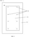
- FIG. 2 is a top view of the example coverboard 100 of FIG. 1 .
- the top facer 110 may include a perimeter region 112, a field region 114, and fastening sites 116.
- the fastening sites 116 may be located in the field region 114.
- the fastening sites 116 are example fastening sites and are provided for illustration purposes only.
- the fastening sites 116 may include more or fewer fastening sites than shown.
- the fastening sites 116 may be locations where the coverboard 100 is attached to a roof using fasteners.
- the fastening sites 116 may be location where screws are driven through the coverboard 100 to attach the coverboard 100 to the roof.
- Fastening the coverboard 100 to the roof at the fastening sites 116 may warp the coverboard 100.
- the coverboard 100 may be pre-warped to compensate for installation warp introduced by fastening the coverboard 100 to the roof, as discussed herein.
- the coverboard 100 may be warped more or less during installation depending on locations of the fastening sites 116. For example, the coverboard 100 may be warped more when the fastening sites 116 are within the field region 114 than when the fastening sites 116 are within the perimeter region 112.
- the pre-warping of the board may be adjusted based on expected locations of the fastening sites 116.
- the expected locations of the fastening sites 116 may depend upon an expected use of the coverboards.
- the coverboard 100 may be warped more or less during installation depending on a composition of the coverboard 100.
- the coverboard 100 may be warped more when the core layer 130 is a thermally-fused blend of paper and plastic fragments than when the core layer 130 is wood.
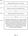
- FIG. 3 is a flow chart 300 illustrating operations for manufacturing a coverboard panel.
- the operations shown may include additional, fewer, or different operations. Additionally, the operations may be performed in the order shown, a different order, or concurrently.
- a bottom facer is placed on a conveyor.
- the conveyor may be a conveyor for manufacturing the coverboard panel.
- the conveyor may be used to manufacture a continuous sheet which is cut into individual coverboard panels.
- the bottom facer may be a synthetic polymer sheet good with a melt-point that is greater than about 350° F.
- the bottom facer can also have a shrinkage level (unconstrained) when heated to a temperature of about 300-450° F of greater than about 1%.
- the synthetic polymer sheet good may be a polyester film.
- the synthetic polymer sheet good may be a nylon film.
- the synthetic polymer sheet good may be a spunbond polyester nonwoven.
- the synthetic polymer sheet good may be a spunbond nylon nonwoven.
- a thickness of the bottom facer may be about 0.0005-0.100 inches.
- the bottom facer may be a multi-layered material as long as one of the layers is a synthetic polymer with a melt-point that is greater than about 350° F.
- a core layer is placed on the bottom facer.
- an adhesive is placed between the bottom facer layer and the core layer.
- the adhesive may be a thermosetting adhesive, a thermoplastic adhesive, a polyethylene film, a polypropylene film, or any type of adhesive or combination of adhesives.
- placing the core layer on the bottom facer includes dispensing a predetermined ratio of paper fragments on the bottom facer layer.
- the paper and plastic fragments may be shaped as irregular plates.
- the paper and plastic fragments may have a diameter of about 0.010-2.000" and a thickness of about 0.005-0.050".
- Paper fragments can be made by milling pieces of paper until the milled material passes a screen with a particular mesh size.
- Paper subjected to the milling process can be newspaper, advertising, office paper, packaging, or other paper products.
- the paper may be virgin material, it may be recycled or sourced from waste streams, or it may be a combination of both. Generating paper fragments from waste or recycling streams has the advantage of being low cost and helps to resolve a world-wide sustainability problem.
- the paper fragments have a thickness and diameter of less than about 0.020" may be used.
- the plastic fragments may include polypropylene, polystyrene, polyester, nylon, rubber (natural and synthetic), polyvinyl chloride, polyethylene (including LLDPE, LDPE, MDPE, HDPE), copolymers of ethylene and propylene, other commercial plastics, or any other plastic.
- polyethylene based plastics especially low and medium density polyethylene resins, may be used.
- the plastic fragments may be a mixture of different types of polymers.
- the plastic may contain plasticizers, such as dioctyl phthalate or benzyl butyl phthalate, colorants, stabilizers, preservatives, and other functional additives.
- the plastic fragments may be prepared by milling pieces of plastic.
- the plastic may be virgin film material, it can be recycled or sourced from waste streams (films, packaging, or a wide array of plastic articles), or the plastic may be a combination of both. Generating plastic fragments from waste or recycling streams has the advantage of being low cost and helps to resolve a world-wide sustainability problem. In some embodiments, plastic fragments having a thickness and a diameter of less than about 0.020" may be used.
- individual fragments may include both paper and plastic.
- many packaging materials found in waste streams include a plurality of alternating paper and plastic layers.
- these packaging materials may include a layer of aluminum foil or a film that has been metalized on one surface.
- fragments derived from all of these materials may be used.
- the core layer may include a variety of materials or combinations of materials.
- the core layer may include an inorganic material, such as gypsum, magnesium oxide, or Portland cement.
- the inorganic material may be fortified with fibers or other additives.
- the core layer may include wood, such as plywood, oriented strandboard, fiberboard, or particleboard.
- the core layer may have a thickness ranging from about 0.1-1.0 inches. In some embodiments, the core layer may have a thickness of about 0.20-0.60 inches. In some embodiments, the core layer may have a density of about 15-75 pounds per cubic foot (PCF). In some embodiments, the core layer may have a density of about 28-65 PCF.
- PCF pounds per cubic foot
- a top facer is placed on the core layer.
- the bottom facer, core layer, and top facer may be placed or otherwise disposed such that the core layer is disposed between the top facer and the bottom facer.
- Placing the top facer may include placing an adhesive between the core layer and the top facer.
- the top facer may be a glass fiber fabric including glass fibers.
- the glass fiber fabric may be a nonwoven fiberglass mat.
- the glass fiber fabric may be a woven glass fiber mat.
- a thickness of the glass fiber fabric may be about 0.005-0.100 inches.
- the top facer may be a top surface of the panel when installed on a roof.
- the bottom facer, the core layer, and the top facer are pressed in a hot press to form a panel, wherein the hot press causes the bottom facer to shrink relative to the top facer, introducing a warp into the panel such that, when installed, the warp compensates for an installation warp and the panel is flat upon installation.
- the hot press may apply heat to the bottom facer, the core layer, and the top facer to cause the bottom facer to shrink.
- the hot press may cause a mixture of paper and plastic fragments in the core layer to thermally fuse.
- the hot press may apply pressure to the bottom facer, the core layer, and the top facer to form the panel.
- the hot press may apply a predetermined amount of heat and a predetermined amount of pressure to ensure the warp compensates for the installation warp.
- any two components so associated can also be viewed as being “operably connected,” or “operably coupled,” to each other to achieve the desired functionality, and any two components capable of being so associated can also be viewed as being “operably couplable,” to each other to achieve the desired functionality.
- operably couplable include but are not limited to physically mateable and/or physically interacting components and/or wirelessly interactable and/or wirelessly interacting components and/or logically interacting and/or logically interactable components.
- Example 1 A panel comprising a core layer and two major surface layers; wherein a first major surface layer is designated as the top major surface layer during an installation event, and the second major surface layer is designated as the bottom major surface layer during an installation event; wherein the top major surface layer comprises a glass fiber fabric and the bottom major surface layer comprises a synthetic polymer sheet good with a melt-point greater than about 350° F.
- Example 2 The panel of example 1, wherein the top major surface layer comprises a nonwoven fiberglass mat.
- Example 3 The panel of example 1, wherein the bottom major surface layer comprises a polyester film.
- Example 4 The panel of example 1, wherein the bottom major surface layer comprises a nylon film.
- Example 5 The panel of example 1, wherein the core layer comprises thermally fused paper and plastic fragments.
- Example 6 The panel of example 1, wherein the core layer comprises wood.
- Example 7 The panel of example 1, wherein the core layer comprises an inorganic cement.
- Example 8 A system for constructing low-slope roofs, wherein roof coverboards comprising a glass fiber top major surface layer and a synthetic polymer sheet good bottom major surface layer are fastened in field regions of the panel and the installed panel are flat after fastening, such that the resulting roof system more effectively drains rainwater.
- Example 9 A system for constructing low-slope roofs, wherein roof coverboards comprising a glass fiber top major surface layer and a synthetic polymer sheet good bottom major surface layer are fastened in field regions of the panel and the installed panel are flat after fastening, such that the installed coverboards facilitate fast, easy and proper installation of the roof membrane.
Landscapes
- Engineering & Computer Science (AREA)
- Chemical & Material Sciences (AREA)
- Architecture (AREA)
- Civil Engineering (AREA)
- Structural Engineering (AREA)
- Ceramic Engineering (AREA)
- Mechanical Engineering (AREA)
- Materials Engineering (AREA)
- Organic Chemistry (AREA)
- Chemical Kinetics & Catalysis (AREA)
- Inorganic Chemistry (AREA)
- Laminated Bodies (AREA)
Applications Claiming Priority (2)
| Application Number | Priority Date | Filing Date | Title |
|---|---|---|---|
| US202263408913P | 2022-09-16 | 2022-09-16 | |
| US18/129,225 US20240102288A1 (en) | 2022-09-16 | 2023-03-31 | Cup-resistant roof coverboard panels |
Publications (1)
| Publication Number | Publication Date |
|---|---|
| EP4338958A1 true EP4338958A1 (fr) | 2024-03-20 |
Family
ID=87567548
Family Applications (1)
| Application Number | Title | Priority Date | Filing Date |
|---|---|---|---|
| EP23190704.9A Pending EP4338958A1 (fr) | 2022-09-16 | 2023-08-09 | Panneaux de couverture de toit résistant aux déformations |
Country Status (3)
| Country | Link |
|---|---|
| US (1) | US20240102288A1 (fr) |
| EP (1) | EP4338958A1 (fr) |
| CA (1) | CA3208529A1 (fr) |
Citations (4)
| Publication number | Priority date | Publication date | Assignee | Title |
|---|---|---|---|---|
| EP0676996B1 (fr) * | 1992-12-30 | 2001-03-07 | MANNHEIM, Jose, R. | Procede de fabrication d' une feuille stratifiee cintree de verre de securite |
| EP0854250B1 (fr) * | 1997-01-17 | 2001-11-14 | Dr. Kohl GmbH & Cie Dachbelag- und Bautenschutzmittel-Fabrik | Bande de toiture avec crampons |
| EP0993935B1 (fr) * | 1998-10-16 | 2008-03-26 | Johnson Controls Headliner GmbH | Procédé de fabrication d'un renfort de toit pour véhicules et renfort fabriqué par ce procédé |
| US11060290B1 (en) | 2019-12-20 | 2021-07-13 | Continuus Materials Intellectual Property, Llc | Roof cover board derived from engineered recycled content |
-
2023
- 2023-03-31 US US18/129,225 patent/US20240102288A1/en active Pending
- 2023-08-04 CA CA3208529A patent/CA3208529A1/fr active Pending
- 2023-08-09 EP EP23190704.9A patent/EP4338958A1/fr active Pending
Patent Citations (4)
| Publication number | Priority date | Publication date | Assignee | Title |
|---|---|---|---|---|
| EP0676996B1 (fr) * | 1992-12-30 | 2001-03-07 | MANNHEIM, Jose, R. | Procede de fabrication d' une feuille stratifiee cintree de verre de securite |
| EP0854250B1 (fr) * | 1997-01-17 | 2001-11-14 | Dr. Kohl GmbH & Cie Dachbelag- und Bautenschutzmittel-Fabrik | Bande de toiture avec crampons |
| EP0993935B1 (fr) * | 1998-10-16 | 2008-03-26 | Johnson Controls Headliner GmbH | Procédé de fabrication d'un renfort de toit pour véhicules et renfort fabriqué par ce procédé |
| US11060290B1 (en) | 2019-12-20 | 2021-07-13 | Continuus Materials Intellectual Property, Llc | Roof cover board derived from engineered recycled content |
Also Published As
| Publication number | Publication date |
|---|---|
| CA3208529A1 (fr) | 2024-03-16 |
| US20240102288A1 (en) | 2024-03-28 |
Similar Documents
| Publication | Publication Date | Title |
|---|---|---|
| US10087634B2 (en) | Roofing systems and methods | |
| US5735092A (en) | Composite roofing members having improved dimensional stability and related methods | |
| US6044604A (en) | Composite roofing members having improved dimensional stability and related methods | |
| US20230340787A1 (en) | Composite membrane for building applications | |
| US9404261B2 (en) | Roofing systems and methods | |
| CA3096340C (fr) | Panneau-toiture derive d'un contenu recycle par ingenierie | |
| US20030082365A1 (en) | Tough and durable insulation boards produced in-part with scrap rubber materials and related methods | |
| US8206817B2 (en) | Window and door flashing, roofing underlayment, protection course, root block and sound control underlayment material products | |
| US20110173910A1 (en) | Composite roofing boards and methods for installing a composite roofing board | |
| US11566427B2 (en) | Enhanced roofing system | |
| US10988933B2 (en) | Flashing assemblies prepared with liquid flashing compositions | |
| US6869661B1 (en) | Flexible radiant barrier | |
| EP4338958A1 (fr) | Panneaux de couverture de toit résistant aux déformations | |
| EP4349587A1 (fr) | Panneaux de couverture de toit résistant à l'eau | |
| US3211597A (en) | Method of roof construction | |
| EP2826620B1 (fr) | Une sous couche multicouche pour l'imperméabilisation d'un toit d'un bâtiment dans lequel ledit toit comporte une couverture de toit métallique. | |
| US20230332410A1 (en) | Roof cover board derived from engineered recycled content | |
| KR102457054B1 (ko) | Tpo 복합 방수시트와 방수시트 조립구조 및 이의 시공방법 | |
| WO2023178190A1 (fr) | Composite précurseur de bande d'étanchéité et ses procédés d'utilisation | |
| EP1601526B1 (fr) | Materiau en feuilles antiderapant a couches multiples | |
| CA2216026A1 (fr) | Elements de toiture a stabilite dimensionnelle amelioree et methodes connexes | |
| MXPA97006591A (es) | Miembros de techado compuestos, que tienen mejorada estabilidad dimensional y metodos relacionados | |
| MXPA98007386A (en) | Composite roofing members who have improved dimensional stability and related methods |
Legal Events
| Date | Code | Title | Description |
|---|---|---|---|
| PUAI | Public reference made under article 153(3) epc to a published international application that has entered the european phase |
Free format text: ORIGINAL CODE: 0009012 |
|
| STAA | Information on the status of an ep patent application or granted ep patent |
Free format text: STATUS: THE APPLICATION HAS BEEN PUBLISHED |
|
| AK | Designated contracting states |
Kind code of ref document: A1 Designated state(s): AL AT BE BG CH CY CZ DE DK EE ES FI FR GB GR HR HU IE IS IT LI LT LU LV MC ME MK MT NL NO PL PT RO RS SE SI SK SM TR |