EP4338679A2 - Ultrasonic diagnosis apparatus and method for controlling ultrasonic diagnosis apparatus - Google Patents
Ultrasonic diagnosis apparatus and method for controlling ultrasonic diagnosis apparatus Download PDFInfo
- Publication number
- EP4338679A2 EP4338679A2 EP24154651.4A EP24154651A EP4338679A2 EP 4338679 A2 EP4338679 A2 EP 4338679A2 EP 24154651 A EP24154651 A EP 24154651A EP 4338679 A2 EP4338679 A2 EP 4338679A2
- Authority
- EP
- European Patent Office
- Prior art keywords
- posture angle
- ultrasound
- probe
- unit
- recommended
- Prior art date
- Legal status (The legal status is an assumption and is not a legal conclusion. Google has not performed a legal analysis and makes no representation as to the accuracy of the status listed.)
- Pending
Links
- 238000000034 method Methods 0.000 title claims description 44
- 238000003745 diagnosis Methods 0.000 title description 8
- 238000002604 ultrasonography Methods 0.000 claims abstract description 401
- 239000000523 sample Substances 0.000 claims abstract description 317
- 238000001514 detection method Methods 0.000 claims abstract description 78
- 238000003384 imaging method Methods 0.000 claims abstract description 58
- 238000010191 image analysis Methods 0.000 claims description 32
- 230000008569 process Effects 0.000 description 23
- 238000005259 measurement Methods 0.000 description 13
- 230000005540 biological transmission Effects 0.000 description 9
- 238000006243 chemical reaction Methods 0.000 description 8
- 230000008859 change Effects 0.000 description 7
- 238000010586 diagram Methods 0.000 description 7
- 238000007476 Maximum Likelihood Methods 0.000 description 6
- 238000004364 calculation method Methods 0.000 description 6
- 230000003321 amplification Effects 0.000 description 5
- 238000003199 nucleic acid amplification method Methods 0.000 description 5
- 230000007704 transition Effects 0.000 description 5
- 238000003909 pattern recognition Methods 0.000 description 4
- 230000001133 acceleration Effects 0.000 description 2
- 230000017531 blood circulation Effects 0.000 description 2
- 229910052451 lead zirconate titanate Inorganic materials 0.000 description 2
- 230000005855 radiation Effects 0.000 description 2
- 238000005070 sampling Methods 0.000 description 2
- BQCIDUSAKPWEOX-UHFFFAOYSA-N 1,1-Difluoroethene Chemical compound FC(F)=C BQCIDUSAKPWEOX-UHFFFAOYSA-N 0.000 description 1
- FYYHWMGAXLPEAU-UHFFFAOYSA-N Magnesium Chemical compound [Mg] FYYHWMGAXLPEAU-UHFFFAOYSA-N 0.000 description 1
- 238000004458 analytical method Methods 0.000 description 1
- 239000000919 ceramic Substances 0.000 description 1
- 239000013078 crystal Substances 0.000 description 1
- 230000001934 delay Effects 0.000 description 1
- 238000002592 echocardiography Methods 0.000 description 1
- 208000014674 injury Diseases 0.000 description 1
- HFGPZNIAWCZYJU-UHFFFAOYSA-N lead zirconate titanate Chemical compound [O-2].[O-2].[O-2].[O-2].[O-2].[Ti+4].[Zr+4].[Pb+2] HFGPZNIAWCZYJU-UHFFFAOYSA-N 0.000 description 1
- 239000004973 liquid crystal related substance Substances 0.000 description 1
- 210000004072 lung Anatomy 0.000 description 1
- 229910052749 magnesium Inorganic materials 0.000 description 1
- 239000011777 magnesium Substances 0.000 description 1
- 238000012986 modification Methods 0.000 description 1
- 230000004048 modification Effects 0.000 description 1
- 229920000642 polymer Polymers 0.000 description 1
- 229920000131 polyvinylidene Polymers 0.000 description 1
- 230000001902 propagating effect Effects 0.000 description 1
- 239000007787 solid Substances 0.000 description 1
- 230000008733 trauma Effects 0.000 description 1
Images


Classifications
-
- A—HUMAN NECESSITIES
- A61—MEDICAL OR VETERINARY SCIENCE; HYGIENE
- A61B—DIAGNOSIS; SURGERY; IDENTIFICATION
- A61B8/00—Diagnosis using ultrasonic, sonic or infrasonic waves
- A61B8/08—Detecting organic movements or changes, e.g. tumours, cysts, swellings
-
- A—HUMAN NECESSITIES
- A61—MEDICAL OR VETERINARY SCIENCE; HYGIENE
- A61B—DIAGNOSIS; SURGERY; IDENTIFICATION
- A61B8/00—Diagnosis using ultrasonic, sonic or infrasonic waves
- A61B8/42—Details of probe positioning or probe attachment to the patient
- A61B8/4245—Details of probe positioning or probe attachment to the patient involving determining the position of the probe, e.g. with respect to an external reference frame or to the patient
- A61B8/4254—Details of probe positioning or probe attachment to the patient involving determining the position of the probe, e.g. with respect to an external reference frame or to the patient using sensors mounted on the probe
-
- A—HUMAN NECESSITIES
- A61—MEDICAL OR VETERINARY SCIENCE; HYGIENE
- A61B—DIAGNOSIS; SURGERY; IDENTIFICATION
- A61B8/00—Diagnosis using ultrasonic, sonic or infrasonic waves
- A61B8/08—Detecting organic movements or changes, e.g. tumours, cysts, swellings
- A61B8/0833—Detecting organic movements or changes, e.g. tumours, cysts, swellings involving detecting or locating foreign bodies or organic structures
- A61B8/085—Detecting organic movements or changes, e.g. tumours, cysts, swellings involving detecting or locating foreign bodies or organic structures for locating body or organic structures, e.g. tumours, calculi, blood vessels, nodules
-
- A—HUMAN NECESSITIES
- A61—MEDICAL OR VETERINARY SCIENCE; HYGIENE
- A61B—DIAGNOSIS; SURGERY; IDENTIFICATION
- A61B8/00—Diagnosis using ultrasonic, sonic or infrasonic waves
- A61B8/13—Tomography
- A61B8/14—Echo-tomography
-
- A—HUMAN NECESSITIES
- A61—MEDICAL OR VETERINARY SCIENCE; HYGIENE
- A61B—DIAGNOSIS; SURGERY; IDENTIFICATION
- A61B8/00—Diagnosis using ultrasonic, sonic or infrasonic waves
- A61B8/42—Details of probe positioning or probe attachment to the patient
- A61B8/4272—Details of probe positioning or probe attachment to the patient involving the acoustic interface between the transducer and the tissue
- A61B8/429—Details of probe positioning or probe attachment to the patient involving the acoustic interface between the transducer and the tissue characterised by determining or monitoring the contact between the transducer and the tissue
-
- A—HUMAN NECESSITIES
- A61—MEDICAL OR VETERINARY SCIENCE; HYGIENE
- A61B—DIAGNOSIS; SURGERY; IDENTIFICATION
- A61B8/00—Diagnosis using ultrasonic, sonic or infrasonic waves
- A61B8/46—Ultrasonic, sonic or infrasonic diagnostic devices with special arrangements for interfacing with the operator or the patient
-
- A—HUMAN NECESSITIES
- A61—MEDICAL OR VETERINARY SCIENCE; HYGIENE
- A61B—DIAGNOSIS; SURGERY; IDENTIFICATION
- A61B8/00—Diagnosis using ultrasonic, sonic or infrasonic waves
- A61B8/52—Devices using data or image processing specially adapted for diagnosis using ultrasonic, sonic or infrasonic waves
- A61B8/5215—Devices using data or image processing specially adapted for diagnosis using ultrasonic, sonic or infrasonic waves involving processing of medical diagnostic data
- A61B8/5223—Devices using data or image processing specially adapted for diagnosis using ultrasonic, sonic or infrasonic waves involving processing of medical diagnostic data for extracting a diagnostic or physiological parameter from medical diagnostic data
-
- A—HUMAN NECESSITIES
- A61—MEDICAL OR VETERINARY SCIENCE; HYGIENE
- A61B—DIAGNOSIS; SURGERY; IDENTIFICATION
- A61B8/00—Diagnosis using ultrasonic, sonic or infrasonic waves
- A61B8/52—Devices using data or image processing specially adapted for diagnosis using ultrasonic, sonic or infrasonic waves
- A61B8/5292—Devices using data or image processing specially adapted for diagnosis using ultrasonic, sonic or infrasonic waves using additional data, e.g. patient information, image labeling, acquisition parameters
-
- A—HUMAN NECESSITIES
- A61—MEDICAL OR VETERINARY SCIENCE; HYGIENE
- A61B—DIAGNOSIS; SURGERY; IDENTIFICATION
- A61B8/00—Diagnosis using ultrasonic, sonic or infrasonic waves
- A61B8/58—Testing, adjusting or calibrating the diagnostic device
-
- A—HUMAN NECESSITIES
- A61—MEDICAL OR VETERINARY SCIENCE; HYGIENE
- A61B—DIAGNOSIS; SURGERY; IDENTIFICATION
- A61B8/00—Diagnosis using ultrasonic, sonic or infrasonic waves
- A61B8/08—Detecting organic movements or changes, e.g. tumours, cysts, swellings
- A61B8/0883—Detecting organic movements or changes, e.g. tumours, cysts, swellings for diagnosis of the heart
-
- A—HUMAN NECESSITIES
- A61—MEDICAL OR VETERINARY SCIENCE; HYGIENE
- A61B—DIAGNOSIS; SURGERY; IDENTIFICATION
- A61B8/00—Diagnosis using ultrasonic, sonic or infrasonic waves
- A61B8/46—Ultrasonic, sonic or infrasonic diagnostic devices with special arrangements for interfacing with the operator or the patient
- A61B8/461—Displaying means of special interest
- A61B8/463—Displaying means of special interest characterised by displaying multiple images or images and diagnostic data on one display
-
- A—HUMAN NECESSITIES
- A61—MEDICAL OR VETERINARY SCIENCE; HYGIENE
- A61B—DIAGNOSIS; SURGERY; IDENTIFICATION
- A61B8/00—Diagnosis using ultrasonic, sonic or infrasonic waves
- A61B8/52—Devices using data or image processing specially adapted for diagnosis using ultrasonic, sonic or infrasonic waves
- A61B8/5215—Devices using data or image processing specially adapted for diagnosis using ultrasonic, sonic or infrasonic waves involving processing of medical diagnostic data
- A61B8/5238—Devices using data or image processing specially adapted for diagnosis using ultrasonic, sonic or infrasonic waves involving processing of medical diagnostic data for combining image data of patient, e.g. merging several images from different acquisition modes into one image
- A61B8/5246—Devices using data or image processing specially adapted for diagnosis using ultrasonic, sonic or infrasonic waves involving processing of medical diagnostic data for combining image data of patient, e.g. merging several images from different acquisition modes into one image combining images from the same or different imaging techniques, e.g. color Doppler and B-mode
-
- A—HUMAN NECESSITIES
- A61—MEDICAL OR VETERINARY SCIENCE; HYGIENE
- A61B—DIAGNOSIS; SURGERY; IDENTIFICATION
- A61B8/00—Diagnosis using ultrasonic, sonic or infrasonic waves
- A61B8/54—Control of the diagnostic device
Definitions
- the present invention relates to an ultrasound diagnostic apparatus and a control method of an ultrasound diagnostic apparatus and in particular, to an ultrasound diagnostic apparatus for notifying an operator of the posture angle of an ultrasound probe with respect to an examination part of a subject and a control method of the ultrasound diagnostic apparatus.
- an ultrasound diagnostic apparatus is known as an apparatus for acquiring an image of the inside of a subject.
- an ultrasound diagnostic apparatus comprises an ultrasound probe comprising a transducer array in which a plurality of elements are arranged.
- an ultrasound beam is transmitted from the transducer array to the inside of the subject and ultrasound echoes from the subject are received in the transducer array, so that element data is acquired.
- the ultrasound diagnostic apparatus electrically processes the acquired element data to generate an ultrasound image of the relevant part of the subject.
- an ultrasound diagnostic apparatus disclosed in JP5842810B displays a reference probe icon, which shows an angle of an ultrasound probe in a case where an ultrasound image was captured in the past or a posture angle set in advance according to the current diagnostic mode, and a current probe icon, which shows a posture angle of an ultrasound probe being moved by the operator, simultaneously with the ultrasound image.
- a reference probe icon which shows an angle of an ultrasound probe in a case where an ultrasound image was captured in the past or a posture angle set in advance according to the current diagnostic mode
- a current probe icon which shows a posture angle of an ultrasound probe being moved by the operator, simultaneously with the ultrasound image.
- the present invention has been made in order to solve such a conventional problem, and it is an object of the present invention to provide an ultrasound diagnostic apparatus and a control method of an ultrasound diagnostic apparatus capable of clearly imaging an examination part even in a case where a subject is changed.
- an ultrasound diagnostic apparatus of the present invention comprises: an ultrasound probe; an image generation unit that generates an ultrasound image by transmitting an ultrasound beam from the ultrasound probe toward a subject and receiving an ultrasound beam reflected from the subject; a probe posture angle detection unit that detects a posture angle of the ultrasound probe; an image analysis unit that calculates a likelihood of an imaging part in the ultrasound image with respect to an examination part by analyzing the ultrasound image generated by the image generation unit; a recommended posture angle generation unit that sets, as a recommended posture angle, the posture angle detected by the probe posture angle detection unit in a case where the likelihood calculated by the image analysis unit is maximized while the posture angle detected by the probe posture angle detection unit is being changed over a predetermined angle range including a basic posture angle of the ultrasound probe, which is set corresponding to the examination part, by bringing the ultrasound probe into contact with a body surface of the subject and tilting the ultrasound probe by an operator; and a recommended posture angle notification unit that notifies the operator of the recommended posture angle generated by the recommended posture angle generation unit.
- the recommended posture angle generation unit sets, as the recommended posture angle, the posture angle detected by the probe posture angle detection unit in a case where the likelihood calculated by the image analysis unit is maximized while the posture angle detected by the probe posture angle detection unit is changing once over the angle range.
- the recommended posture angle generation unit sets, as the recommended posture angle, the posture angle detected by the probe posture angle detection unit in a case where the likelihood calculated by the image analysis unit is maximized while the posture angle detected by the probe posture angle detection unit is changing in a reciprocating manner over the angle range.
- the display control unit displays, on the display unit, the likelihood calculated by the image analysis unit, the posture angle detected by the probe posture angle detection unit, the basic posture angle, and the recommended posture angle generated by the recommended posture angle generation unit.
- the display control unit displays the posture angle detected by the probe posture angle detection unit, the basic posture angle, and the recommended posture angle generated by the recommended posture angle generation unit, on the display unit, as numerical values or graph images.
- a control method of an ultrasound diagnostic apparatus of the present invention comprises: generating an ultrasound image by transmitting an ultrasound beam from an ultrasound probe toward a subject and receiving an ultrasound beam reflected from the subject; detecting a posture angle of the ultrasound probe; calculating a likelihood of an imaging part in the ultrasound image with respect to an examination part by analyzing the generated ultrasound image; setting, as a recommended posture angle, the posture angle in a case where the calculated likelihood is maximized while the detected posture angle is being changed over a predetermined angle range including a basic posture angle of the ultrasound probe, which is set corresponding to the examination part, by bringing the ultrasound probe into contact with a body surface of the subject and tilting the ultrasound probe by an operator; and notifying the operator of the recommended posture angle.
- the ultrasound diagnostic apparatus has the recommended posture angle generation unit that sets, as a recommended posture angle, the posture angle of the ultrasound probe in a case where the likelihood of the imaging part in the ultrasound image is maximized, and the operator is notified of the recommended posture angle. Therefore, even in a case where the subject is changed, it is possible to image the examination part clearly.
- FIG. 1 shows the configuration of an ultrasound diagnostic apparatus according to a first embodiment of the present invention.
- An ultrasound diagnostic apparatus 1 comprises an ultrasound probe 2 in which a transducer array 2A is built, and a display control unit 7 and a display unit 8 are sequentially connected to the ultrasound probe 2 through an image acquisition unit 3.
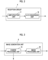
- the image acquisition unit 3 has a reception circuit 4 and a transmission circuit 5, which are connected to the transducer array 2A of the ultrasound probe 2, and an image generation unit 6 connected to the reception circuit 4, and the display control unit 7 is connected to the image generation unit 6.
- the ultrasound probe 2 comprises a probe posture angle detection unit 9, and a recommended posture angle generation unit 11 is connected to the probe posture angle detection unit 9.
- An image analysis unit 10 is connected to the image generation unit 6 of the image acquisition unit 3, and the recommended posture angle generation unit 11 is connected to the image analysis unit 10.
- a recommended posture angle notification unit 12 is connected to the recommended posture angle generation unit 11, and the recommended posture angle notification unit 12 is connected to the display control unit 7.
- An apparatus control unit 13 is connected to the image acquisition unit 3, the display control unit 7, the probe posture angle detection unit 9, the image analysis unit 10, the recommended posture angle generation unit 11, and the recommended posture angle notification unit 12, and an operation unit 14, a storage unit 15, and a memory 16 are connected to the apparatus control unit 13.
- the apparatus control unit 13 and the storage unit 15 are connected to each other so that information can be transmitted and received bidirectionally, and the apparatus control unit 13 and the memory 16 are connected to each other so that information can be transmitted and received bidirectionally.
- the transducer array 2A of the ultrasound probe 2 shown in Fig. 1 has a plurality of elements (ultrasound transducer) arranged in a one-dimensional or two-dimensional manner. According to a driving signal supplied from the transmission circuit 5, each of the elements transmits an ultrasound wave and receives an ultrasound echo from the subject and outputs a reception signal.
- each element is formed by using a transducer in which electrodes are formed at both ends of a piezoelectric body formed of piezoelectric ceramic represented by lead zirconate titanate (PZT), a polymer piezoelectric element represented by poly vinylidene di fluoride (PVDF), piezoelectric single crystal represented by lead magnesium niobate-lead titanate (PMN-PT), or the like.
- PZT lead zirconate titanate
- PVDF polymer piezoelectric element represented by poly vinylidene di fluoride
- PMN-PT piezoelectric single crystal represented by lead magnesium niobate-lead titanate
- the piezoelectric body expands and contracts to generate pulsed or continuous-wave ultrasound waves from each transducer. From the combined wave of these ultrasound waves, an ultrasound beam is formed.
- the respective transducers expand and contract by receiving the propagating ultrasound waves, thereby generating electric signals. These electric signals are output, as reception signals of the ultrasound waves, from each transducer to the reception circuit 4.
- the reception circuit 4 of the image acquisition unit 3 has a configuration in which an amplification unit 17 and an analog/digital (A/D) conversion unit 18 are connected in series to each other.
- the amplification unit 17 amplifies the reception signal output from each element of the transducer array 2A
- the A/D conversion unit 18 converts the amplified signal into a digital signal to obtain element data and outputs the obtained element data to the image generation unit 6.
- the transmission circuit 5 of the image acquisition unit 3 includes, for example, a plurality of pulse generators. Based on a transmission delay pattern selected according to the control signal from the apparatus control unit 13, the transmission circuit 5 adjusts the amount of delay of each driving signal so that ultrasound waves transmitted from the plurality of elements of the transducer array 2A form an ultrasound beam, and supplies the obtained signals to the plurality of elements.
- the image generation unit 6 of the image acquisition unit 3 has a configuration in which a brightness mode (B mode) processing unit 19 and an image processing unit 20 are sequentially connected in series to each other.
- B mode brightness mode
- the B mode processing unit 19 Based on the reception delay pattern selected according to the control signal from the apparatus control unit 13, the B mode processing unit 19 performs reception focusing processing in which delays are given to respective pieces of element data according to the set sound speed and addition (phasing addition) is performed. Through the reception focusing processing, a sound ray signal with narrowed focus of the ultrasound echo is generated.
- the B mode processing unit 19 generates a B mode image signal, which is tomographic image information regarding tissues inside the subject, by correcting the attenuation of the sound ray signal due to the propagation distance according to the depth of the reflection position of the ultrasound wave and then performing envelope detection processing.
- the B mode image signal generated by the B mode processing unit 19 is output to the display control unit 7 and the image analysis unit 10.
- the image processing unit 20 converts (raster conversion) the B mode image signal generated by the B mode processing unit 19 into an image signal according to the normal television signal scanning method and performs various kinds of required image processing, such as gradation processing, on the B mode image signal, and then outputs the B mode image signal to the display control unit 7.
- the display control unit 7 of ultrasound diagnostic apparatus 1 displays an ultrasound diagnostic image on the display unit 8 based on the B mode image signal acquired by the image acquisition unit 3.
- the display unit 8 includes, for example, a display device, such as a liquid crystal display (LCD), and displays an ultrasound diagnostic image under the control of the apparatus control unit 13.
- a display device such as a liquid crystal display (LCD)
- LCD liquid crystal display
- the ultrasound probe 2 comprises the probe posture angle detection unit 9, and the probe posture angle detection unit 9 detects the posture angle of the ultrasound probe 2 that is brought into contact with the body surface of the subject and tilted by the operator during ultrasound diagnosis.
- the probe posture angle detection unit 9 detects the angles of three components defined based on three axes perpendicular to each other in a three-dimensional space.
- the three axes perpendicular to each other in the three-dimensional space are defined as follows. That is, a direction perpendicular to the ultrasound wave emission surface of the ultrasound probe 2 is defined as the x axis, and directions perpendicular to each other along the ultrasound wave emission surface of the ultrasound probe 2 are defined as the y axis and the z axis, respectively.
- the probe posture angle detection unit 9 detects an angle in a case where the x axis is a horizontal direction as a pitch angle, detects an angle in a case where the y axis is a horizontal direction as a roll angle, and detects an angle in a case where the z axis is a vertical direction as a yaw angle.
- the probe posture angle detection unit 9 is not particularly limited as long as the posture angle of the ultrasound probe 2 can be detected. Although not shown, the following description will be given on the assumption that the probe posture angle detection unit 9 is attached to the ultrasound probe 2, includes three angle sensors that detect a pitch angle, a roll angle, and a yaw angle as electric signals, and detects the posture angle of the ultrasound probe 2 as angle information by converting electric signals acquired from the angle sensors into angle information.
- the image analysis unit 10 performs image analysis, such as pattern recognition, on the B mode image signal generated by the B mode processing unit 19 of the image generation unit 6 of the image acquisition unit 3, thereby calculating the likelihood of an imaging part in the ultrasound image with respect to the examination part.
- the likelihood of the imaging part in the ultrasound image with respect to the examination part in the present invention is a numerical value indicating the likelihood of the imaging part in the ultrasound image with respect to the examination part, and it can be determined that, as the numerical value of the likelihood becomes larger, the probability that the imaging part in the ultrasound image is the examination part becomes higher, that is, the imaging part in the ultrasound image is clearly imaged as the examination part.
- the imaging part in the ultrasound image is more clearly imaged as the heart that is an examination part.
- the recommended posture angle generation unit 11 is a characteristic element of the present invention.
- the recommended posture angle generation unit 11 sets, as a recommended posture angle, a posture angle in a case where the likelihood of the imaging part in the ultrasound image calculated by the image analysis unit 10 is maximized while the posture angle of the ultrasound probe 2 detected by the probe posture angle detection unit 9 is changing over a predetermined angle range including the basic posture angle of the ultrasound probe 2.
- the angle range refers to an angle range having two different angles as upper and lower limits.
- the basic posture angle is a posture angle of the ultrasound probe 2 set in advance corresponding to the examination part, and is a posture angle of the ultrasound probe 2 at which the examination part of the subject can be imaged so that the imaging part in the ultrasound image becomes clear with respect to the general structure and position of the examination part.
- the recommended posture angle is generated based on the posture angle of the ultrasound probe 2 during ultrasound diagnosis and the image analysis result of the captured ultrasound image. Therefore, the recommended posture angle is a posture angle of the ultrasound probe 2 at which the examination part of the subject can be imaged so that the imaging part in the ultrasound image becomes clear with respect to the unique structure and position of the examination part of the subject who is a target of ultrasound diagnosis.
- the recommended posture angle notification unit 12 notifies the operator of the recommended posture angle generated by the recommended posture angle generation unit 11.
- the notification method of the recommended posture angle notification unit 12 is not particularly limited as long as the operator can be notified of the recommended posture angle.
- the following description will be given on the assumption that the recommended posture angle notification unit 12 transmits instruction information for displaying the recommended posture angle on the display unit 8 to the display control unit 7.
- the apparatus control unit 13 controls each unit of the ultrasound diagnostic apparatus 1 based on a command input by the operator through the operation unit 14.
- the operation unit 14 is for the operator to perform an input operation, and can be configured to comprise a keyboard, a mouse, a trackball, a touch panel, and the like.
- the storage unit 15 stores an operation program and the like of the ultrasound diagnostic apparatus 1, and recording media, such as a hard disc drive (HDD), a solid state drive (SSD), a flexible disc (FD), a magneto-optical disc (MO), a magnetic tape (MT), a random access memory (RAM), a compact disc (CD), a digital versatile disc (DVD), a secure digital card (SD card), and a universal serial bus memory (USB memory), or a server can be used.
- HDD hard disc drive
- SSD solid state drive
- FD flexible disc
- MO magneto-optical disc
- MT magnetic tape
- RAM random access memory
- CD compact disc
- DVD digital versatile disc
- SD card secure digital card
- USB memory universal serial bus memory
- the memory 16 stores an examination part label for designating an examination part, the basic posture angle of the ultrasound probe 2, the recommended posture angle of the ultrasound probe 2, the posture angle of the ultrasound probe 2 detected by the probe posture angle detection unit 9, the likelihood of an imaging part calculated by the image analysis unit 10, and the like.
- recording media such as an HDD, an SSD, an FD, an MO disk, an MT, a RAM, a CD, a DVD, an SD card, and a USB memory, a server, and the like can be used.
- the image generation unit 6 of the image acquisition unit 3, the display control unit 7, the image analysis unit 10, the recommended posture angle generation unit 11, the recommended posture angle notification unit 12, and the apparatus control unit 13 are configured by a central processing unit (CPU) and an operation program causing the CPU to execute various kinds of processing. However, these may also be configured using a digital circuit and a computer.
- the image generation unit 6, the display control unit 7, the image analysis unit 10, the recommended posture angle generation unit 11, and the apparatus control unit 13 can also be integrated partially or entirely in one CPU.
- the probe posture angle detection unit 9 may be configured to include a CPU and an operation program causing the CPU to execute various kinds of processing, these may also be configured using a digital circuit and a computer, and can be partially integrated in one CPU together with the image generation unit 6, the display control unit 7, the image analysis unit 10, the recommended posture angle generation unit 11, and the apparatus control unit 13.
- step S1 the apparatus control unit 13 acquires an examination part label for designating a part of a subject, which is to be imaged in the following steps, from the memory 16.
- each unit of the ultrasound diagnostic apparatus 1 performs processing corresponding to the examination part designated by the examination part label.
- an examination protocol that is the order of examination parts to be subjected to ultrasound diagnosis in examination facilities and the like is often determined in advance in many cases. Therefore, in the operation of the ultrasound diagnostic apparatus 1 to be described below, description will be given on the assumption that the examination part label sequentially transitions according to a predetermined examination protocol.
- step S2 the apparatus control unit 13 further acquires a basic posture angle corresponding to the examination part, which is designated by the examination part label acquired in step S1, from the memory 16.
- step S3 the apparatus control unit 13 transmits, to the display control unit 7, instruction information for displaying the basic posture angle acquired in step S2 on the display unit 8, and the display control unit 7 displays the basic posture angle on the display unit 8.
- the operator brings the ultrasound probe 2 into contact with the body surface of the subject and tilts the ultrasound probe 2 with reference to the basic posture angle displayed on the display unit 8, thereby being able to capture an ultrasound image.
- step S4 while the operator brings the ultrasound probe 2 into contact with the body surface of the subject and tilts the ultrasound probe 2, the posture angle of the ultrasound probe 2, that is, the pitch angle, the roll angle, and the yaw angle of the ultrasound probe 2 are detected by the probe posture angle detection unit 9.
- step S5 scanning and transmission and reception of ultrasound beams using a plurality of ultrasound transducers of the transducer array 2A of the ultrasound probe 2, that is, capturing of an ultrasound image, is performed by the reception circuit 4 and the transmission circuit 5 of the image acquisition unit 3.
- a reception signal is output to the reception circuit 4 from each ultrasound transducer that has received the ultrasound echo from the subject, and amplification and A/D conversion of the reception signal are performed by the amplification unit 17 and the A/D conversion unit 18 of the reception circuit 4 to generate a reception signal.
- step S6 the reception signal is input to the image generation unit 6, and a B mode image, that is, an ultrasound image is generated by the B mode processing unit 19 of the image generation unit 6.
- the image analysis unit 10 can perform pattern recognition, such as a template matching, calculate the similarity between the part included in the ultrasound image and the template of a plurality of parts as a score, and sets the calculated score as the likelihood of the imaging part in the ultrasound image.
- steps S4 and S5 to S7 are performed synchronously and in parallel. That is, by the processing of steps S4 to S7, the posture angle of the ultrasound probe 2 at the time of generating the ultrasound image by the image generation unit 6 and the likelihood of the imaging part in the generated ultrasound image can be obtained in parallel.
- Fig. 5 shows a display example on the display unit 8 in a case where the heart is imaged.
- the likelihood of an imaging part with respect to the heart is displayed as a part likelihood together with an ultrasound image 21, it is displayed that the examination part is the heart, and the basic posture angle and the current posture angle of the ultrasound probe 2 are displayed using numerical values as a pitch angle ⁇ p, a roll angle ⁇ r, and a yaw angle ⁇ g and a radar chart 22.
- a graph 22a for the basic posture angle and a graph 22b for the posture angle of the current ultrasound probe 2 are displayed with the pitch angle ⁇ p, the roll angle ⁇ r, and the yaw angle ⁇ g as three axes.
- An annotation image 22c for explaining the two graphs 22a and 22b displayed within the radar chart 22 can also be displayed on the radar chart 22.
- the operator can clearly image the examination part of the subject according to the basic posture angle by tilting the ultrasound probe 2 so that the radar chart and the numerical value of the current posture angle of the ultrasound probe 2 match the radar chart and the numerical value of the basic posture angle.
- step S8 subsequent to steps S4 to S7, the apparatus control unit 13 determines whether or not the examination part of the subject being currently examined has transitioned to another part. For example, in a case where the examination part transitions from the heart to the lung, the apparatus control unit 13 determines that the examination part has been changed. In general, in a case where the examination part is changed, the ultrasound probe 2 is separated from the body surface of the subject to become in an air radiation state. By detecting the air radiation state, that is, a state in which the reflection signal from the transducer array 2A cannot be obtained in the reception circuit 4, it is possible to determine the presence or absence of transition of the examination part. In a case where it is determined that the examination part has transitioned in step S8, the process returns to step S 1 to acquire a new examination part label according to the predetermined examination protocol, and the processing of steps S2 to S7 is newly performed thereafter.
- step S8 In a case where it is determined that the examination part has not been changed, that is, the same examination part is examined in step S8, the process proceeds to step S9.
- step S9 the apparatus control unit 13 determines whether or not to end the examination being currently performed. For example, in a case where the operator inputs instruction information for ending the examination to the apparatus control unit 13 through the operation unit 14, the apparatus control unit 13 determines that the examination being currently performed is to be ended. In a case where the apparatus control unit 13 determines that the examination is to be ended as described above, the current examination in the ultrasound diagnostic apparatus 1 is ended.
- the apparatus control unit 13 determines that the examination being currently performed is not to be ended. In a case where the apparatus control unit 13 determines that the examination is not to be ended as described above, the process proceeds to step S10.
- step S10 the apparatus control unit 13 stores the posture angle of the ultrasound probe 2 detected in step S4 and the likelihood of the imaging part calculated in step S7 in the memory 16.
- the apparatus control unit 13 determines whether or not the posture angle of the ultrasound probe 2 detected in step S4 has changed once over a predetermined angle range including the basic posture angle displayed in step S3.
- the posture angle of the ultrasound probe 2 changes once over the predetermined angle range means that a series of changes, such as a change in the posture angle of the ultrasound probe 2 from a value exceeding the upper limit of the predetermined angle range to a value in the angle range and a change from the value in the angle range to a value less than the lower limit of the angle range, are made once.
- the posture angle of the ultrasound probe 2 changes once over the predetermined angle range refers to one-time change from a value less than the lower limit of the angle range to a value exceeding the upper limit.
- step S11 in a case where the apparatus control unit 13 determines that the posture angle of the ultrasound probe 2 has not changed in one direction as described above over the predetermined angle range including the basic posture angle displayed in step S3, the process returns to step S4 and step S5.
- generation of an ultrasound image, detection of the posture angle of the ultrasound probe 2, and calculation of the likelihood of an imaging part are newly performed, and the newly detected posture angle of the ultrasound probe 2 and the newly calculated likelihood of the imaging part are newly stored in the memory 16.
- step S12 the apparatus control unit 13 acquires a maximum likelihood among the plurality of likelihoods stored in the memory 16 in a case where the processing of steps S4 to S11 is repeated, and acquires the posture angle of the ultrasound probe 2 corresponding to the maximum likelihood, that is, the posture angle of the ultrasound probe 2 detected in synchronization with the maximum likelihood.
- the recommended posture angle generation unit 11 sets the posture angle of the ultrasound probe 2 acquired in step S12 as a recommended posture angle for the current examination part.
- the recommended posture angle notification unit 12 transmits, to the display control unit 7, instruction information for displaying the recommended posture angle acquired in step S13 on the display unit 8 instead of the basic posture angle.
- the recommended posture angle is displayed at the location where the basic posture angle is displayed.
- step S14 Upon completion of step S14, the process returns to step S4 and step S5. In the subsequent processing, as long as the examination part does not transition in step S8 or as long as the end of the examination is not determined in step S9, the processing of steps S4 to S14 is repeated. At this time, in a case where a likelihood greater than the likelihood of the imaging part corresponding to the recommended posture angle acquired in step S13 is calculated, the maximum likelihood is updated in step S12, the posture angle of the ultrasound probe 2 corresponding to the updated likelihood is set as a new recommended posture angle in step S13, and the new recommended posture angle is displayed on the display unit 8 in step S14.
- a recommended posture angle that is an optimal posture angle of the ultrasound probe 2 at which the examination part of the subject can be clearly imaged in accordance with the structure, the position, and the like of the part of the subject, and the operator can be notified of the recommended posture angle by displaying the recommended posture angle on the display unit 8. Therefore, the operator can clearly image the part even in a case where the subject is changed by capturing an ultrasound image while referring to the recommended angle displayed on the display unit 8.
- the probe posture angle detection unit 9 is not particularly limited as long as the posture angle of the ultrasound probe 2 can be detected.
- an acceleration sensor e.g., a Bosch Sensortec BMA150 accelerometer
- a gyro sensor e.g., a Bosch Sensortec BMA150 accelerometer
- a magnetic sensor e.g., a Bosch Sensortec BMA150 gyro sensor
- a global positioning system (GPS) sensor e.g., a global positioning system (GPS) sensor, and the like.
- GPS global positioning system
- These sensors may be mounted on the ultrasound probe 2 or may be built into the ultrasound probe 2.
- the examination part label is acquired according to the examination protocol, but the method of acquiring the examination part label is not particularly limited. That is, the examination part label can also be input to the operator through the operation unit 14, or can also be determined by performing part determination by the ultrasound diagnostic apparatus 1.
- the examination part label is determined by part determination
- an ultrasound image can be generated by the same processing as in steps S5 and S6, likelihoods of respective imaging parts with respect to a plurality of examination parts can be calculated by analyzing the generated ultrasound image, and an examination part corresponding to the maximum likelihood among the likelihoods can be set as a part label.
- the likelihood of each imaging part with respect to a plurality of examination parts may be displayed in the part likelihood field displayed on the display unit 8, or the examination part field may be displayed as a determination result field and the examination part determined as the examination label in the field may be displayed.
- the part determination is not limited to the method described above.
- the apparatus control unit 13 can perform part determination by a known method using a result of motion analysis or the like on imaging parts in a plurality of captured ultrasound images.
- an image showing the relationship between the ultrasound probe 2 and the x axis, the y axis, and the z axis and the relationship between the ultrasound probe 2 and the pitch angle ⁇ p, the roll angle ⁇ r, and the yaw angle ⁇ g can also be added.
- the operator can easily check how the pitch angle ⁇ p, the roll angle ⁇ r, and the yaw angle ⁇ g displayed on the display unit 8 are defined. Therefore, even an operator unfamiliar with the ultrasound diagnostic apparatus 1 can clearly image the examination part of the subject relatively easily by tilting the ultrasound probe 2 while referring to the display on the display unit 8.
- the apparatus control unit 13 and the recommended posture angle notification unit 12 transmit, to the display control unit 7, instruction information for displaying the basic posture angle and the recommended posture angle on the display unit 8.
- the notification method of the basic posture angle and the recommended posture angle is not particularly limited to the method.
- the recommended posture angle notification unit 12 and the apparatus control unit 13 can also notify the operator of the basic posture angle and the recommended posture angle by sound.
- the basic posture angle and the current posture angle of the ultrasound probe 2 are displayed using the radar chart 22.
- the basic posture angle and the current posture angle of the ultrasound probe 2 can also be displayed using other display methods.
- a model of an ultrasound probe can be displayed so as to be superimposed on a schema that is a two-dimensional display of a model of the human body, and a guide showing a rotation direction aiming at the basic posture angle with respect to the current posture angle of the ultrasound probe 2 can be displayed.
- the guide display may be displayed using an image, such as an arrow, or may be accompanied by sound.
- the posture angle of the ultrasound probe 2 includes a pitch angle, a roll angle, and a yaw angle, but guidance can be performed using screen display, sound, and the like for each component of the three components, or can be performed at the same time for a plurality of components.
- the same display method and the guide method as for the basic posture angle can be applied to the recommended posture angle.
- the B mode image is generated using the element data obtained by ultrasound beam scanning in step S5.
- measurement information such as the Doppler information and modulus-of-elasticity information of the imaging part
- a Doppler image generation unit is provided in the ultrasound diagnostic apparatus 1, Doppler measurements, such as color Doppler measurement and power Doppler measurement, are performed at the time of ultrasound beam scanning in step S5, and a colored image obtained by the Doppler measurement is displayed so as to be superimposed on the B mode image, so that it is possible to generate a Doppler image, such as a color Doppler image or a power Doppler image.
- the modulus of elasticity of the imaging part can be measured.
- a modulus-of-elasticity image generation unit is provided in the ultrasound diagnostic apparatus 1, and a modulus-of-elasticity map obtained by elasticity measurement is displayed so as to be superimposed on the B mode image, so that it is possible to generate a modulus-of-elasticity image.
- the likelihood of the imaging part is calculated by performing pattern recognition on the B mode image generated in step S6.
- the present invention is not limited to the pattern recognition as long as the likelihood of the imaging part can be calculated.
- the likelihood of the imaging part can also be calculated by analyzing the measurement results.
- the likelihood of the imaging part can be calculated by analyzing the Doppler information, such as the distribution of the blood flow and the speed of the blood flow in the imaging part, and referring to the look-up table stored in advance in the storage unit 15 or the memory 16.
- Steps S4 and S5 to S7 are performed synchronously and in parallel.
- steps S4 and S5 to S7 may not be performed synchronously and in parallel as long as the posture angle of the ultrasound probe 2 detected in step S4 and the likelihood of the imaging part calculated in step S7 can be associated with each other. That is, as long as the posture angle detected in step S4 and the likelihood calculated in step S7 are stored so as to be associated with each other in step S10, steps S5 to S7 may be performed immediately after step S4 is completed, or step S4 may be performed immediately after step S7 is completed.
- the posture angle of the ultrasound probe 2 detected in step S4 and the likelihood of the imaging part calculated in step S7 are stored in the memory 16 in step S10.
- the timing at which the detected posture angle of the ultrasound probe 2 and the calculated likelihood of the imaging part are stored may be any timing as long as the timing is in a range from the completion time of step S4 and step S7 to immediately before step S11.
- the posture angle of the ultrasound probe 2 detected immediately after completion of step S4 can be stored in the memory 16, and the likelihood of the imaging part can be stored in the memory 16 immediately after completion of step S7.
- the angle range used in step S11 is not particularly limited as long as the basic posture angle is included therein.
- the posture angle of the ultrasound probe 2 is changed with the basic posture angle as a reference, it is preferable to use a predetermined angle range having a certain range on the upper limit side and the lower limit side with the basic posture angle as the center.
- the apparatus control unit 13 can perform determination using one predetermined angle, that is, the basic posture angle acquired in step S2, instead of performing determination as to whether or not the posture angle of the ultrasound probe 2 detected in step S4 has changed once over an angle range that includes the basic posture angle and has predetermined different upper and lower limits.
- step S11 in a case where the apparatus control unit 13 performs determination using the basic posture angle, the apparatus control unit 13 determines whether or not the posture angle of the ultrasound probe 2 detected in step S4 has changed in one direction across the basic posture angle. That is, the apparatus control unit 13 determines whether or not the posture angle of the ultrasound probe 2 has changed from an angle less than the basic posture angle to an angle exceeding the basic posture angle or determines whether or not the posture angle of the ultrasound probe 2 has changed from an angle exceeding the basic posture angle to an angle less than the basic posture angle.
- step S12 in a case where the apparatus control unit 13 determines that the posture angle of the ultrasound probe 2 has not changed in one direction across the basic posture angle, the process returns to step S4 and step S5. On the other hand, in a case where the apparatus control unit 13 determines that the posture angle of the ultrasound probe 2 has changed in one direction across the basic posture angle, the process proceeds to step S12.
- the recommended posture angle generated in step S13 is used as the one predetermined angle.
- step S11 of determining whether or not the posture angle of the ultrasound probe 2 has changed once over the predetermined angle range including the basic posture angle it is possible to obtain a recommended posture angle that is an optimum posture angle of the ultrasound probe 2 at which the examination part of the subject can be clearly imaged in accordance with the structure, the position, and the like of the part of the subject.
- the ultrasound diagnostic apparatus 1 may be a portable ultrasound diagnostic apparatus that can be easily carried and used, or may be a stationary ultrasound diagnostic apparatus that is installed and used in the examination room or the like.
- the ultrasound probe 2 is not particularly limited as long as transmission of an ultrasound beam toward the subject and reception of an ultrasound beam reflected from the subject are possible, and may be in the form of a sector type, a convex type, a linear type, a radial type, or the like.
- the posture angle of the ultrasound probe 2 at which the likelihood of the imaging part is maximized in a case where the posture angle of the ultrasound probe 2 detected by the probe posture angle detection unit 9 has changed in one direction over the predetermined angle range is set as a recommended posture angle.
- the flowchart of Fig. 7 shows the operation of an ultrasound diagnostic apparatus according to a second embodiment of the present invention.
- the ultrasound diagnostic apparatus of the second embodiment is the same as the ultrasound diagnostic apparatus 1 of the first embodiment shown in Figs. 1 to 3 . Therefore, in the following description, the same reference numerals as for the elements of the ultrasound diagnostic apparatus 1 are used, and the detailed description of each element will be omitted.
- Steps S1 to S10 in the second embodiment shown in Fig. 7 are the same as steps S1 to S10 in the first embodiment shown in Fig. 4 .
- After acquisition of the examination part label, acquisition and display of the basic posture angle, detection of the posture angle of the ultrasound probe 2, generation of the ultrasound image, and calculation of the likelihood of the imaging part, determination as to whether or not the examination part has transitioned and determination as to whether or not to end the examination are performed.
- the posture angle of the ultrasound probe 2 detected in step S4 and the likelihood of the imaging part calculated in step S7 are stored in the memory 16 in step S10, the process proceeds to step S15.
- step S15 the apparatus control unit 13 determines whether or not the posture angle of the ultrasound probe 2 detected in step S4 has changed in a reciprocating manner over a predetermined angle range including the basic posture angle displayed in step S3.
- the posture angle of the ultrasound probe 2 changes in a reciprocating manner over a predetermined angle range means that the posture angle of the ultrasound probe 2 changes from a value less than the lower limit of the predetermined angle range to a value exceeding the upper limit immediately after changing from a value exceeding the upper limit of the predetermined angle range to a value less than the lower limit or, on the contrary, that the posture angle of the ultrasound probe 2 changes from a value less than the lower limit of the predetermined angle range so as to return to the value less than the lower limit through the value exceeding the upper limit.
- step S15 in a case where the apparatus control unit 13 determines that the posture angle of the ultrasound probe 2 has not changed in a reciprocating manner over the predetermined angle range including the basic posture angle displayed in step S3, the process returns to step S4 and step S5.
- generation of an ultrasound image, detection of the posture angle of the ultrasound probe 2, and calculation of the likelihood of an imaging part are newly performed, and the newly detected posture angle of the ultrasound probe 2 and the newly calculated likelihood of the imaging part are newly stored in the memory 16.
- Subsequent steps S12 to S14 are the same as steps S12 to S14 in the first embodiment shown in Fig. 4 . That is, the posture angle of the ultrasound probe 2 corresponding to the maximum likelihood among the plurality of likelihoods stored in the memory 16 is set as a recommended posture angle and the recommended posture angle is displayed on the display unit 8, and the process returns to step S4 and step S5.
- the posture angle of the ultrasound probe 2 in a reciprocating manner over the predetermined angle range rather than changing the posture angle of the ultrasound probe 2 in one direction over the predetermined angle range, it is possible to increase the sampling number of the likelihood of the imaging part and the posture angle of the ultrasound probe 2 in the predetermined angle range. Therefore, according to the second embodiment of the present invention, since the probability of acquiring a more appropriate recommended posture angle for the subject can be increased, the operator can image the examination part of the subject more clearly.
- determination using one predetermined angle can be performed instead of performing determination using an angle range having predetermined different upper and lower limits as in step S15.
- the apparatus control unit 13 determines whether or not the posture angle of the ultrasound probe 2 detected in step S4 has changed in a reciprocating manner across the basic posture angle. That is, the apparatus control unit 13 determines whether or not the posture angle of the ultrasound probe 2 has changed from an angle less than the basic posture angle to an angle exceeding the basic posture angle and has changed from an angle exceeding the basic posture angle to an angle less than the basic posture angle.
- step S12 in a case where the apparatus control unit 13 determines that the posture angle of the ultrasound probe 2 has not changed in a reciprocating manner across the basic posture angle, the process returns to step S4 and step S5. On the other hand, in a case where the apparatus control unit 13 determines that the posture angle of the ultrasound probe 2 has changed in a reciprocating manner across the basic posture angle, the process proceeds to step S12.
- FIG. 8 shows the configuration of an ultrasound diagnostic apparatus according to a third embodiment of the present invention.
- An ultrasound diagnostic apparatus 23 shown in Fig. 8 is the same as the ultrasound diagnostic apparatus 1 shown in Figs. 1 to 3 except that a probe angular speed detection unit 24 and a probe tilt warning unit 25. Therefore, in the ultrasound diagnostic apparatus 23, the same reference numerals are used for the same elements as in the ultrasound diagnostic apparatus 1, and the detailed description of each element will be omitted.
- the ultrasound probe 2 comprises the probe angular speed detection unit 24, and the apparatus control unit 13 is connected to the probe angular speed detection unit 24.
- the probe tilt warning unit 25 is connected to the apparatus control unit 13, and the probe tilt warning unit 25 is connected to the display control unit 7.
- the probe angular speed detection unit 24 detects the angular speed of the ultrasound probe 2 that is brought into contact with the body surface of the subject and tilted by the operator. In this case, the probe angular speed detection unit 24 detects the angular speeds of three components centered on three axes perpendicular to each other in a three-dimensional space. For example, it is possible to detect three angular speeds centered on the x axis, the y axis, and the z axis described above with respect to the ultrasound probe 2. In the following description, it is assumed that the probe angular speed detection unit 24 detects the three angular speeds of three components centered on the x axis, the y axis, and the z axis.
- the probe angular speed detection unit 24 is not particularly limited as long as the angular speed of the ultrasound probe 2 can be detected. Although not shown, the following description will be given on the assumption that the probe angular speed detection unit 24 is attached to the ultrasound probe 2, includes a gyro sensor that detects the angular speeds of three components centered on the x axis, the y axis, and the z axis as electric signals, and detects angular speed information of the ultrasound probe 2 by converting the electric signal obtained from the gyro sensor into angular speed information.
- the probe tilt warning unit 25 warns the operator that the ultrasound probe 2 is to be continuously tilted in a case where the angular speed of the ultrasound probe 2 detected by the probe angular speed detection unit 24 becomes equal to or less than a determined value.
- the probe tilt warning unit 25 can warn the operator that the ultrasound probe 2 is to be continuously tilted using various methods, the following description will be given on the assumption that the probe tilt warning unit 25 transmits, to the display control unit 7, instruction information for displaying a text to continuously tilt the ultrasound probe 2 on the display unit 8.
- Steps S1 to S11 are the same as steps S1 to S11 in the flowchart according to the first embodiment shown in Fig. 4 .
- Acquisition of the examination part label, acquisition of the basic posture angle, display of the basic posture angle on the display unit 8, detection of the posture angle of the ultrasound probe 2, generation of the ultrasound image, and calculation of the likelihood of the examination part are performed, and determination as to whether or not the examination part has transitioned and determination as to whether or not to end the examination are performed.
- the posture angle detected in step S4 and the likelihood of the imaging part calculated in step S7 are stored in the memory 16, and it is determined whether or not the detected posture angle of the ultrasound probe 2 has changed in one direction over the predetermined angle range.
- step S16 in a case where the apparatus control unit 13 determines that the posture angle of the ultrasound probe 2 detected in step S4 has not changed in one direction over the predetermined angle range in step S11, the process proceeds to step S16.
- step S16 while the operator brings the ultrasound probe 2 into contact with the body surface of the subject and tilts the ultrasound probe 2, the angular speed of the ultrasound probe 2 is detected by the probe angular speed detection unit 24.
- step S17 the apparatus control unit 13 determines whether or not the posture angle of the ultrasound probe 2 is within a predetermined angle range and whether or not the absolute value of the angular speed of the ultrasound probe 2 detected in step S24 is equal to or less than a predetermined value V
- the value V is set to a positive value close to "0", for example. Then, in a case where the apparatus control unit 13 determines that the angular speed of the ultrasound probe 2 exceeds the predetermined value V, it is determined that the ultrasound probe 2 is in contact with the body surface of the subject and is continuously tilted, and the process returns to step S4 and step S5.
- step S 18 the probe tilt warning unit 25 transmits instruction information, which is for displaying a warning that the ultrasound probe 2 is to be continuously tilted without being stopped on the display unit 8, to the display control unit 7 under the control of the apparatus control unit 13. As a result, a warning that the ultrasound probe 2 is to be continuously tilted is displayed on the display unit 8.
- step S18 Upon completion of step S18, the process returns to step S4 and step S5.
- steps S4 to S11 and steps S16 to S18 are repeated.
- the process proceeds to step S12.
- Steps S12 to S14 are the same as steps S12 to S14 in the flowchart according to the first embodiment shown in Fig. 4 , and the posture angle of the ultrasound probe 2 at which the likelihood of the imaging part is maximized is set as a recommended posture angle and the recommended posture angle is displayed on the display unit 8 instead of the basic posture angle.
- the third embodiment of the present invention in a case where the tilting of the ultrasound probe 2 is about to stop while the ultrasound probe 2 is being tilted by the operator, a warning that the ultrasound probe 2 is to be continuously tilted is given to the operator. As a result, it is possible to promote a change in the posture angle of the ultrasound probe 2, that is, it is possible to promote generation of a recommended posture angle.
- a gyro sensor that detects the angular speeds of three components centered on the x axis, the y axis, and the z axis in the ultrasound probe 2 is used as the probe angular speed detection unit 24.
- the probe angular speed detection unit 24 is not particularly limited as long as the angular speed of the ultrasound probe 2 of at least three components can be detected.
- a plurality of gyro sensors that detect only the angular speed of one component can be used, or a plurality of gyro sensors that detect the angular speeds of two components can be used, or a combination of these gyro sensors can be used.
- an acceleration sensor instead of the gyro sensor, an acceleration sensor, a magnetic sensor, a GPS sensor, and the like can also be used. In this case, it is possible to provide an apparatus that converts an electric signal obtained from each sensor into the angular speed of the ultrasound probe 2 using a known calculation method. These sensors may be mounted on the ultrasound probe 2 or may be built into the ultrasound probe 2.
- a sensor for calculating the posture angle of the ultrasound probe 2 and a sensor for calculating the angular speed of the ultrasound probe 2 can be the same sensor.
- a conversion apparatus for converting the electric signal obtained from the sensor into the posture angle of the ultrasound probe 2 and a conversion apparatus for converting the electric signal obtained from the sensor into the angular speed of the ultrasound probe 2 can be provided in the probe posture angle detection unit 9 and the probe angular speed detection unit 24, respectively.
- the probe tilt warning unit 25 transmits, to the display control unit 7, instruction information for displaying a text to continuously tilt the ultrasound probe 2 on the display unit 8.
- the warning method of the probe tilt warning unit 25 is not limited thereto as long as a warning that the ultrasound probe 2 is to be continuously tilted can be given to the operator.
- the probe tilt warning unit 25 can also transmit, to the display control unit 7, instruction information for displaying an image to continuously tilt the ultrasound probe 2 on the display unit 8.
- the warning to the operator by the probe tilt warning unit 25 is not limited to that displayed on the display unit 8.
- an apparatus for generating a sound such as a speaker
- the probe tilt warning unit 25 can generate a sound to continuously tilt the ultrasound probe 2 in the apparatus for generating a sound.
- a light source such as a lamp
- the probe tilt warning unit 25 can turn on the lamp or the like as a warning that the ultrasound probe 2 is to be continuously tilted.
- the warning of the probe tilt warning unit 25 can include guide information indicating the tilting direction of the ultrasound probe 2.
- the guide information refers to an image such as an arrow and a text for giving an instruction to change the posture angle of the ultrasound probe 2 to a value less than the lower limit of the angle range, a sound, and the like.
- the guide information refers to an image such as an arrow and a text for giving an instruction to change the posture angle of the ultrasound probe 2 to a value exceeding the upper limit of the angle range, a sound, and the like.
- step S17 the apparatus control unit 13 determines whether or not the absolute value of the angular speed of the ultrasound probe 2 detected in step S16 is equal to or less than the predetermined value V
- the predetermined value V is a small value so as not to disturb the examination due to excessive warning in step S18.
- the posture angle of the ultrasound probe 2 at which the likelihood of the imaging part is maximized in a case where the posture angle of the ultrasound probe 2 detected by the probe posture angle detection unit 9 has changed in one direction over the predetermined angle range is set as a recommended posture angle.
- the posture angle of the ultrasound probe 2 at which the likelihood of the imaging part is maximized in a case where the posture angle of the ultrasound probe 2 detected by the probe posture angle detection unit 9 has changed in a reciprocating manner over the predetermined angle range may be set as a recommended posture angle.
- the flowchart of Fig. 10 shows the operation of an ultrasound diagnostic apparatus according to a fourth embodiment.
- the ultrasound diagnostic apparatus of the fourth embodiment is the same as the ultrasound diagnostic apparatus 23 of the third embodiment shown in Fig. 8 . Therefore, in the following description, the same reference numerals as for the elements forming the ultrasound diagnostic apparatus 23 are used, and the detailed description of each element will be omitted.
- the flowchart shown in Fig. 10 is the same as the flowchart of the third embodiment shown in Fig. 9 except that step S15 is performed instead of step S11.
- step S15 in the flowchart of Fig. 10 is the same as step S15 in the flowchart of the second embodiment shown in Fig. 7 .
- step S16 in a case where the apparatus control unit 13 determines that the posture angle of the ultrasound probe 2 detected in step S4 has not changed in a reciprocating manner over the predetermined angle range in step S15, the process proceeds to step S16.
- step S18 the angular speed of the ultrasound probe 2 is detected, and the process returns to step S4 and step S5 in a case where the absolute value of the angular speed exceeds the predetermined value V
- a warning that the ultrasound probe 2 is to be continuously tilted is given by the probe tilt warning unit 25, and then the process returns to step S4 and step S5.
- the fourth embodiment of the present invention rather than changing the posture angle of the ultrasound probe 2 in one direction over the predetermined angle range, it is possible to increase the sampling number of the likelihood of the imaging part and the posture angle of the ultrasound probe 2 in the predetermined angle range.
- the operator by warning the operator that the ultrasound probe 2 is to be continuously tilted in a case where the tilting of the ultrasound probe 2 is about to stop while the operator is changing the posture angle of the ultrasound probe 2 in a reciprocating manner over the predetermined angle range, it is possible to promote generation of a recommended posture angle.
Abstract
An ultrasound diagnostic apparatus has: a recommended posture angle generation unit that sets, as a recommended posture angle, a posture angle of an ultrasound probe in a case where the likelihood of an imaging part in an ultrasound image with respect to an examination part is maximized while the posture angle of a probe posture angle detection unit is being changed over a predetermined angle range including a basic posture angle of the ultrasound probe, which is set corresponding to the examination part, by bringing the ultrasound probe into contact with the body surface of a subject and tilting the ultrasound probe by an operator; and a recommended posture angle notification unit that notifies the operator of the recommended posture angle generated by the recommended posture angle generation unit.
Description
- The present invention relates to an ultrasound diagnostic apparatus and a control method of an ultrasound diagnostic apparatus and in particular, to an ultrasound diagnostic apparatus for notifying an operator of the posture angle of an ultrasound probe with respect to an examination part of a subject and a control method of the ultrasound diagnostic apparatus.
- Conventionally, an ultrasound diagnostic apparatus is known as an apparatus for acquiring an image of the inside of a subject. In general, an ultrasound diagnostic apparatus comprises an ultrasound probe comprising a transducer array in which a plurality of elements are arranged. In a state in which the ultrasound probe is in contact with the body surface of the subject, an ultrasound beam is transmitted from the transducer array to the inside of the subject and ultrasound echoes from the subject are received in the transducer array, so that element data is acquired. In addition, the ultrasound diagnostic apparatus electrically processes the acquired element data to generate an ultrasound image of the relevant part of the subject.
- It is known that the clarity of an imaging part in the ultrasound image captured by such an ultrasound diagnostic apparatus changes according to the posture angle of the ultrasound probe in contact with the body surface of the subject. For this reason, at the time of examining the part of the subject using the ultrasound diagnostic apparatus, in order to clearly image the examination part of the subject, the operator needs to bring the ultrasound probe into contact with the body surface of the subject and tilt the ultrasound probe to find the optimal posture angle of the ultrasound probe.
- Therefore, various ultrasound diagnostic apparatuses capable of acquiring the appropriate posture angle of the ultrasound probe and clearly imaging the examination part of the subject have been proposed. For example, an ultrasound diagnostic apparatus disclosed in
JP5842810B - Incidentally, since the structure and the position of an examination part vary depending on a subject, an appropriate posture angle of an ultrasound probe differs depending on a subject. For this reason, even in a case where the posture angle of the ultrasound probe is determined with reference to a reference posture angle set in advance using the technique disclosed in
JP5842810B - For example, in the extended Focused Assessment with Sonography for Trauma (eFAST) examination for continuously examining a plurality of examination parts for initial examination of an injured patient in emergency, it is requested to quickly perform ultrasound examination on the plurality of examination parts. In the case of such an examination, the examination has been performed on a subject having no past ultrasound diagnostic data in many cases, and the examination time is short. Therefore, even in a case where the technique disclosed in
JP5842810B - The present invention has been made in order to solve such a conventional problem, and it is an object of the present invention to provide an ultrasound diagnostic apparatus and a control method of an ultrasound diagnostic apparatus capable of clearly imaging an examination part even in a case where a subject is changed.
- In order to achieve the aforementioned object, an ultrasound diagnostic apparatus of the present invention comprises: an ultrasound probe; an image generation unit that generates an ultrasound image by transmitting an ultrasound beam from the ultrasound probe toward a subject and receiving an ultrasound beam reflected from the subject; a probe posture angle detection unit that detects a posture angle of the ultrasound probe; an image analysis unit that calculates a likelihood of an imaging part in the ultrasound image with respect to an examination part by analyzing the ultrasound image generated by the image generation unit; a recommended posture angle generation unit that sets, as a recommended posture angle, the posture angle detected by the probe posture angle detection unit in a case where the likelihood calculated by the image analysis unit is maximized while the posture angle detected by the probe posture angle detection unit is being changed over a predetermined angle range including a basic posture angle of the ultrasound probe, which is set corresponding to the examination part, by bringing the ultrasound probe into contact with a body surface of the subject and tilting the ultrasound probe by an operator; and a recommended posture angle notification unit that notifies the operator of the recommended posture angle generated by the recommended posture angle generation unit.
- It is preferable that the recommended posture angle generation unit sets, as the recommended posture angle, the posture angle detected by the probe posture angle detection unit in a case where the likelihood calculated by the image analysis unit is maximized while the posture angle detected by the probe posture angle detection unit is changing once over the angle range.
- Alternatively, it is preferable that the recommended posture angle generation unit sets, as the recommended posture angle, the posture angle detected by the probe posture angle detection unit in a case where the likelihood calculated by the image analysis unit is maximized while the posture angle detected by the probe posture angle detection unit is changing in a reciprocating manner over the angle range.
- It is preferable to further comprise: a probe angular speed detection unit that detects an angular speed of the ultrasound probe; and a probe tilt warning unit that warns the operator that the ultrasound probe is to be continuously tilted in a case where the posture angle detected by the probe posture angle detection unit is within the angle range and the angular speed detected by the probe angular speed detection unit becomes equal to or less than a predetermined value.
- It is preferable to further comprise: a display unit that displays the ultrasound image generated by the image generation unit; and a display control unit that controls display on the display unit.
- It is preferable that the display control unit displays, on the display unit, the likelihood calculated by the image analysis unit, the posture angle detected by the probe posture angle detection unit, the basic posture angle, and the recommended posture angle generated by the recommended posture angle generation unit.
- It is preferable that the display control unit displays the posture angle detected by the probe posture angle detection unit, the basic posture angle, and the recommended posture angle generated by the recommended posture angle generation unit, on the display unit, as numerical values or graph images.
- A control method of an ultrasound diagnostic apparatus of the present invention comprises: generating an ultrasound image by transmitting an ultrasound beam from an ultrasound probe toward a subject and receiving an ultrasound beam reflected from the subject; detecting a posture angle of the ultrasound probe; calculating a likelihood of an imaging part in the ultrasound image with respect to an examination part by analyzing the generated ultrasound image; setting, as a recommended posture angle, the posture angle in a case where the calculated likelihood is maximized while the detected posture angle is being changed over a predetermined angle range including a basic posture angle of the ultrasound probe, which is set corresponding to the examination part, by bringing the ultrasound probe into contact with a body surface of the subject and tilting the ultrasound probe by an operator; and notifying the operator of the recommended posture angle.
- According to the present invention, the ultrasound diagnostic apparatus has the recommended posture angle generation unit that sets, as a recommended posture angle, the posture angle of the ultrasound probe in a case where the likelihood of the imaging part in the ultrasound image is maximized, and the operator is notified of the recommended posture angle. Therefore, even in a case where the subject is changed, it is possible to image the examination part clearly.
-
-
Fig. 1 is a block diagram showing the configuration of an ultrasound diagnostic apparatus according to a first embodiment of the present invention. -
Fig. 2 is a block diagram showing the internal configuration of a reception circuit shown inFig. 1 . -
Fig. 3 is a block diagram showing the internal configuration of an image generation unit shown inFig. 1 . -
Fig. 4 is a flowchart showing the operation of the ultrasound diagnostic apparatus according to the first embodiment of the present invention. -
Fig. 5 is a conceptual diagram showing an example of a screen display during ultrasound diagnosis on a display unit shown inFig. 1 . -
Fig. 6 is a conceptual diagram showing an example of a display of a radar chart on the display unit shown inFig. 1 . -
Fig. 7 is a flowchart showing the operation of an ultrasound diagnostic apparatus according to a second embodiment of the present invention. -
Fig. 8 is a block diagram showing the configuration of an ultrasound diagnostic apparatus according to a third embodiment of the present invention. -
Fig. 9 is a flowchart showing the operation of the ultrasound diagnostic apparatus according to the third embodiment of the present invention. -
Fig. 10 is a flowchart showing the operation of an ultrasound diagnostic apparatus according to a fourth embodiment of the present invention. - Hereinafter, embodiments of the present invention will be described with reference to the accompanying diagrams.
-
Fig. 1 shows the configuration of an ultrasound diagnostic apparatus according to a first embodiment of the present invention. An ultrasounddiagnostic apparatus 1 comprises anultrasound probe 2 in which atransducer array 2A is built, and adisplay control unit 7 and adisplay unit 8 are sequentially connected to theultrasound probe 2 through animage acquisition unit 3. - The
image acquisition unit 3 has areception circuit 4 and atransmission circuit 5, which are connected to thetransducer array 2A of theultrasound probe 2, and animage generation unit 6 connected to thereception circuit 4, and thedisplay control unit 7 is connected to theimage generation unit 6. Theultrasound probe 2 comprises a probe posture angle detection unit 9, and a recommended postureangle generation unit 11 is connected to the probe posture angle detection unit 9. Animage analysis unit 10 is connected to theimage generation unit 6 of theimage acquisition unit 3, and the recommended postureangle generation unit 11 is connected to theimage analysis unit 10. A recommended postureangle notification unit 12 is connected to the recommended postureangle generation unit 11, and the recommended postureangle notification unit 12 is connected to thedisplay control unit 7. - An
apparatus control unit 13 is connected to theimage acquisition unit 3, thedisplay control unit 7, the probe posture angle detection unit 9, theimage analysis unit 10, the recommended postureangle generation unit 11, and the recommended postureangle notification unit 12, and anoperation unit 14, astorage unit 15, and amemory 16 are connected to theapparatus control unit 13. Theapparatus control unit 13 and thestorage unit 15 are connected to each other so that information can be transmitted and received bidirectionally, and theapparatus control unit 13 and thememory 16 are connected to each other so that information can be transmitted and received bidirectionally. - The
transducer array 2A of theultrasound probe 2 shown inFig. 1 has a plurality of elements (ultrasound transducer) arranged in a one-dimensional or two-dimensional manner. According to a driving signal supplied from thetransmission circuit 5, each of the elements transmits an ultrasound wave and receives an ultrasound echo from the subject and outputs a reception signal. For example, each element is formed by using a transducer in which electrodes are formed at both ends of a piezoelectric body formed of piezoelectric ceramic represented by lead zirconate titanate (PZT), a polymer piezoelectric element represented by poly vinylidene di fluoride (PVDF), piezoelectric single crystal represented by lead magnesium niobate-lead titanate (PMN-PT), or the like. - In a case where a pulsed or continuous-wave voltage is applied to the electrodes of such a transducer, the piezoelectric body expands and contracts to generate pulsed or continuous-wave ultrasound waves from each transducer. From the combined wave of these ultrasound waves, an ultrasound beam is formed. The respective transducers expand and contract by receiving the propagating ultrasound waves, thereby generating electric signals. These electric signals are output, as reception signals of the ultrasound waves, from each transducer to the
reception circuit 4. - As shown in
Fig. 2 , thereception circuit 4 of theimage acquisition unit 3 has a configuration in which anamplification unit 17 and an analog/digital (A/D)conversion unit 18 are connected in series to each other. In thereception circuit 4, theamplification unit 17 amplifies the reception signal output from each element of thetransducer array 2A, and the A/D conversion unit 18 converts the amplified signal into a digital signal to obtain element data and outputs the obtained element data to theimage generation unit 6. - The
transmission circuit 5 of theimage acquisition unit 3 includes, for example, a plurality of pulse generators. Based on a transmission delay pattern selected according to the control signal from theapparatus control unit 13, thetransmission circuit 5 adjusts the amount of delay of each driving signal so that ultrasound waves transmitted from the plurality of elements of thetransducer array 2A form an ultrasound beam, and supplies the obtained signals to the plurality of elements. - As shown in
Fig. 3 , theimage generation unit 6 of theimage acquisition unit 3 has a configuration in which a brightness mode (B mode)processing unit 19 and animage processing unit 20 are sequentially connected in series to each other. - Based on the reception delay pattern selected according to the control signal from the
apparatus control unit 13, the Bmode processing unit 19 performs reception focusing processing in which delays are given to respective pieces of element data according to the set sound speed and addition (phasing addition) is performed. Through the reception focusing processing, a sound ray signal with narrowed focus of the ultrasound echo is generated. The Bmode processing unit 19 generates a B mode image signal, which is tomographic image information regarding tissues inside the subject, by correcting the attenuation of the sound ray signal due to the propagation distance according to the depth of the reflection position of the ultrasound wave and then performing envelope detection processing. The B mode image signal generated by the Bmode processing unit 19 is output to thedisplay control unit 7 and theimage analysis unit 10. - The
image processing unit 20 converts (raster conversion) the B mode image signal generated by the Bmode processing unit 19 into an image signal according to the normal television signal scanning method and performs various kinds of required image processing, such as gradation processing, on the B mode image signal, and then outputs the B mode image signal to thedisplay control unit 7. - As shown in
Fig. 1 , thedisplay control unit 7 of ultrasounddiagnostic apparatus 1 displays an ultrasound diagnostic image on thedisplay unit 8 based on the B mode image signal acquired by theimage acquisition unit 3. - The
display unit 8 includes, for example, a display device, such as a liquid crystal display (LCD), and displays an ultrasound diagnostic image under the control of theapparatus control unit 13. - The
ultrasound probe 2 comprises the probe posture angle detection unit 9, and the probe posture angle detection unit 9 detects the posture angle of theultrasound probe 2 that is brought into contact with the body surface of the subject and tilted by the operator during ultrasound diagnosis. In this case, the probe posture angle detection unit 9 detects the angles of three components defined based on three axes perpendicular to each other in a three-dimensional space. Here, the three axes perpendicular to each other in the three-dimensional space are defined as follows. That is, a direction perpendicular to the ultrasound wave emission surface of theultrasound probe 2 is defined as the x axis, and directions perpendicular to each other along the ultrasound wave emission surface of theultrasound probe 2 are defined as the y axis and the z axis, respectively. In this case, the probe posture angle detection unit 9 detects an angle in a case where the x axis is a horizontal direction as a pitch angle, detects an angle in a case where the y axis is a horizontal direction as a roll angle, and detects an angle in a case where the z axis is a vertical direction as a yaw angle. - The probe posture angle detection unit 9 is not particularly limited as long as the posture angle of the
ultrasound probe 2 can be detected. Although not shown, the following description will be given on the assumption that the probe posture angle detection unit 9 is attached to theultrasound probe 2, includes three angle sensors that detect a pitch angle, a roll angle, and a yaw angle as electric signals, and detects the posture angle of theultrasound probe 2 as angle information by converting electric signals acquired from the angle sensors into angle information. - The
image analysis unit 10 performs image analysis, such as pattern recognition, on the B mode image signal generated by the Bmode processing unit 19 of theimage generation unit 6 of theimage acquisition unit 3, thereby calculating the likelihood of an imaging part in the ultrasound image with respect to the examination part. Here, the likelihood of the imaging part in the ultrasound image with respect to the examination part in the present invention is a numerical value indicating the likelihood of the imaging part in the ultrasound image with respect to the examination part, and it can be determined that, as the numerical value of the likelihood becomes larger, the probability that the imaging part in the ultrasound image is the examination part becomes higher, that is, the imaging part in the ultrasound image is clearly imaged as the examination part. For example, in a case where an ultrasound image of the heart is captured using the ultrasounddiagnostic apparatus 1, it can be determined that, as the numerical value of the likelihood of an imaging part in the ultrasound image with respect to the heart that is an examination part becomes larger, the imaging part in the ultrasound image is more clearly imaged as the heart that is an examination part. - The recommended posture
angle generation unit 11 is a characteristic element of the present invention. The recommended postureangle generation unit 11 sets, as a recommended posture angle, a posture angle in a case where the likelihood of the imaging part in the ultrasound image calculated by theimage analysis unit 10 is maximized while the posture angle of theultrasound probe 2 detected by the probe posture angle detection unit 9 is changing over a predetermined angle range including the basic posture angle of theultrasound probe 2. Here, the angle range refers to an angle range having two different angles as upper and lower limits. The basic posture angle is a posture angle of theultrasound probe 2 set in advance corresponding to the examination part, and is a posture angle of theultrasound probe 2 at which the examination part of the subject can be imaged so that the imaging part in the ultrasound image becomes clear with respect to the general structure and position of the examination part. Compared with the basic posture angle, the recommended posture angle is generated based on the posture angle of theultrasound probe 2 during ultrasound diagnosis and the image analysis result of the captured ultrasound image. Therefore, the recommended posture angle is a posture angle of theultrasound probe 2 at which the examination part of the subject can be imaged so that the imaging part in the ultrasound image becomes clear with respect to the unique structure and position of the examination part of the subject who is a target of ultrasound diagnosis. - The recommended posture
angle notification unit 12 notifies the operator of the recommended posture angle generated by the recommended postureangle generation unit 11. The notification method of the recommended postureangle notification unit 12 is not particularly limited as long as the operator can be notified of the recommended posture angle. Hereinafter, the following description will be given on the assumption that the recommended postureangle notification unit 12 transmits instruction information for displaying the recommended posture angle on thedisplay unit 8 to thedisplay control unit 7. - The
apparatus control unit 13 controls each unit of the ultrasounddiagnostic apparatus 1 based on a command input by the operator through theoperation unit 14. - The
operation unit 14 is for the operator to perform an input operation, and can be configured to comprise a keyboard, a mouse, a trackball, a touch panel, and the like. - The
storage unit 15 stores an operation program and the like of the ultrasounddiagnostic apparatus 1, and recording media, such as a hard disc drive (HDD), a solid state drive (SSD), a flexible disc (FD), a magneto-optical disc (MO), a magnetic tape (MT), a random access memory (RAM), a compact disc (CD), a digital versatile disc (DVD), a secure digital card (SD card), and a universal serial bus memory (USB memory), or a server can be used. - The
memory 16 stores an examination part label for designating an examination part, the basic posture angle of theultrasound probe 2, the recommended posture angle of theultrasound probe 2, the posture angle of theultrasound probe 2 detected by the probe posture angle detection unit 9, the likelihood of an imaging part calculated by theimage analysis unit 10, and the like. As thememory 16, similarly to thestorage unit 15, recording media, such as an HDD, an SSD, an FD, an MO disk, an MT, a RAM, a CD, a DVD, an SD card, and a USB memory, a server, and the like can be used. - The
image generation unit 6 of theimage acquisition unit 3, thedisplay control unit 7, theimage analysis unit 10, the recommended postureangle generation unit 11, the recommended postureangle notification unit 12, and theapparatus control unit 13 are configured by a central processing unit (CPU) and an operation program causing the CPU to execute various kinds of processing. However, these may also be configured using a digital circuit and a computer. Theimage generation unit 6, thedisplay control unit 7, theimage analysis unit 10, the recommended postureangle generation unit 11, and theapparatus control unit 13 can also be integrated partially or entirely in one CPU. Although the probe posture angle detection unit 9 may be configured to include a CPU and an operation program causing the CPU to execute various kinds of processing, these may also be configured using a digital circuit and a computer, and can be partially integrated in one CPU together with theimage generation unit 6, thedisplay control unit 7, theimage analysis unit 10, the recommended postureangle generation unit 11, and theapparatus control unit 13. - Next, the operation of the ultrasound
diagnostic apparatus 1 in the first embodiment will be described with reference to the flowchart shown inFig. 4 . Here, it is assumed that the examination part label and the basic posture angle are stored in advance in thememory 16. - First, in step S1, the
apparatus control unit 13 acquires an examination part label for designating a part of a subject, which is to be imaged in the following steps, from thememory 16. Thus, in the following steps, each unit of the ultrasounddiagnostic apparatus 1 performs processing corresponding to the examination part designated by the examination part label. - Here, in continuous diagnosis such as so-called eFAST examination, an examination protocol that is the order of examination parts to be subjected to ultrasound diagnosis in examination facilities and the like is often determined in advance in many cases. Therefore, in the operation of the ultrasound
diagnostic apparatus 1 to be described below, description will be given on the assumption that the examination part label sequentially transitions according to a predetermined examination protocol. - In step S2, the
apparatus control unit 13 further acquires a basic posture angle corresponding to the examination part, which is designated by the examination part label acquired in step S1, from thememory 16. - In subsequent step S3, the
apparatus control unit 13 transmits, to thedisplay control unit 7, instruction information for displaying the basic posture angle acquired in step S2 on thedisplay unit 8, and thedisplay control unit 7 displays the basic posture angle on thedisplay unit 8. In the following steps, the operator brings theultrasound probe 2 into contact with the body surface of the subject and tilts theultrasound probe 2 with reference to the basic posture angle displayed on thedisplay unit 8, thereby being able to capture an ultrasound image. - In step S4, while the operator brings the
ultrasound probe 2 into contact with the body surface of the subject and tilts theultrasound probe 2, the posture angle of theultrasound probe 2, that is, the pitch angle, the roll angle, and the yaw angle of theultrasound probe 2 are detected by the probe posture angle detection unit 9. - In step S5, scanning and transmission and reception of ultrasound beams using a plurality of ultrasound transducers of the
transducer array 2A of theultrasound probe 2, that is, capturing of an ultrasound image, is performed by thereception circuit 4 and thetransmission circuit 5 of theimage acquisition unit 3. In this case, a reception signal is output to thereception circuit 4 from each ultrasound transducer that has received the ultrasound echo from the subject, and amplification and A/D conversion of the reception signal are performed by theamplification unit 17 and the A/D conversion unit 18 of thereception circuit 4 to generate a reception signal. - In subsequent step S6, the reception signal is input to the
image generation unit 6, and a B mode image, that is, an ultrasound image is generated by the Bmode processing unit 19 of theimage generation unit 6. - Then, in a case where the ultrasound image generated in step S6 is input to the
image analysis unit 10, image analysis on the ultrasound image is performed by theimage analysis unit 10 and as a result, the likelihood of the imaging part in the ultrasound image with respect to the examination part is calculated in step S7. In this case, for example, theimage analysis unit 10 can perform pattern recognition, such as a template matching, calculate the similarity between the part included in the ultrasound image and the template of a plurality of parts as a score, and sets the calculated score as the likelihood of the imaging part in the ultrasound image. - The above-described steps S4 and S5 to S7 are performed synchronously and in parallel. That is, by the processing of steps S4 to S7, the posture angle of the
ultrasound probe 2 at the time of generating the ultrasound image by theimage generation unit 6 and the likelihood of the imaging part in the generated ultrasound image can be obtained in parallel. - Upon completion of the processing of steps S4 to S7, the posture angle of the
ultrasound probe 2 detected in step S4 and the likelihood calculated in step S7 are displayed together with the ultrasound image generated in step S6 on thedisplay unit 8, for example, as shown inFig. 5. Fig. 5 shows a display example on thedisplay unit 8 in a case where the heart is imaged. InFig. 5 , the likelihood of an imaging part with respect to the heart is displayed as a part likelihood together with anultrasound image 21, it is displayed that the examination part is the heart, and the basic posture angle and the current posture angle of theultrasound probe 2 are displayed using numerical values as a pitch angle θp, a roll angle θr, and a yaw angle θg and aradar chart 22. In theradar chart 22, for example, as shown inFig. 6 , agraph 22a for the basic posture angle and agraph 22b for the posture angle of thecurrent ultrasound probe 2 are displayed with the pitch angle θp, the roll angle θr, and the yaw angle θg as three axes. Anannotation image 22c for explaining the twographs radar chart 22 can also be displayed on theradar chart 22. - As described above, the operator can clearly image the examination part of the subject according to the basic posture angle by tilting the
ultrasound probe 2 so that the radar chart and the numerical value of the current posture angle of theultrasound probe 2 match the radar chart and the numerical value of the basic posture angle. - In step S8 subsequent to steps S4 to S7, the
apparatus control unit 13 determines whether or not the examination part of the subject being currently examined has transitioned to another part. For example, in a case where the examination part transitions from the heart to the lung, theapparatus control unit 13 determines that the examination part has been changed. In general, in a case where the examination part is changed, theultrasound probe 2 is separated from the body surface of the subject to become in an air radiation state. By detecting the air radiation state, that is, a state in which the reflection signal from thetransducer array 2A cannot be obtained in thereception circuit 4, it is possible to determine the presence or absence of transition of the examination part. In a case where it is determined that the examination part has transitioned in step S8, the process returns to stepS 1 to acquire a new examination part label according to the predetermined examination protocol, and the processing of steps S2 to S7 is newly performed thereafter. - In a case where it is determined that the examination part has not been changed, that is, the same examination part is examined in step S8, the process proceeds to step S9.
- In step S9, the
apparatus control unit 13 determines whether or not to end the examination being currently performed. For example, in a case where the operator inputs instruction information for ending the examination to theapparatus control unit 13 through theoperation unit 14, theapparatus control unit 13 determines that the examination being currently performed is to be ended. In a case where theapparatus control unit 13 determines that the examination is to be ended as described above, the current examination in the ultrasounddiagnostic apparatus 1 is ended. - For example, in a case where the operator does not input instruction information for ending the examination through the
operation unit 14, theapparatus control unit 13 determines that the examination being currently performed is not to be ended. In a case where theapparatus control unit 13 determines that the examination is not to be ended as described above, the process proceeds to step S10. - In step S10, the
apparatus control unit 13 stores the posture angle of theultrasound probe 2 detected in step S4 and the likelihood of the imaging part calculated in step S7 in thememory 16. - In subsequent step S11, the
apparatus control unit 13 determines whether or not the posture angle of theultrasound probe 2 detected in step S4 has changed once over a predetermined angle range including the basic posture angle displayed in step S3. Here, "the posture angle of theultrasound probe 2 changes once over the predetermined angle range" means that a series of changes, such as a change in the posture angle of theultrasound probe 2 from a value exceeding the upper limit of the predetermined angle range to a value in the angle range and a change from the value in the angle range to a value less than the lower limit of the angle range, are made once. In addition, similarly to the above, "the posture angle of theultrasound probe 2 changes once over the predetermined angle range" refers to one-time change from a value less than the lower limit of the angle range to a value exceeding the upper limit. - In step S11, in a case where the
apparatus control unit 13 determines that the posture angle of theultrasound probe 2 has not changed in one direction as described above over the predetermined angle range including the basic posture angle displayed in step S3, the process returns to step S4 and step S5. In this case, generation of an ultrasound image, detection of the posture angle of theultrasound probe 2, and calculation of the likelihood of an imaging part are newly performed, and the newly detected posture angle of theultrasound probe 2 and the newly calculated likelihood of the imaging part are newly stored in thememory 16. Thus, as a result of the tilting of theultrasound probe 2 by the operator while repeating the steps S4 to S10, in a case where theapparatus control unit 13 determines that the posture angle of theultrasound probe 2 has changed in one direction as described above over the predetermined angle range, the process proceeds to step S12. - In step S12, the
apparatus control unit 13 acquires a maximum likelihood among the plurality of likelihoods stored in thememory 16 in a case where the processing of steps S4 to S11 is repeated, and acquires the posture angle of theultrasound probe 2 corresponding to the maximum likelihood, that is, the posture angle of theultrasound probe 2 detected in synchronization with the maximum likelihood. - In subsequent step S13, the recommended posture
angle generation unit 11 sets the posture angle of theultrasound probe 2 acquired in step S12 as a recommended posture angle for the current examination part. - In subsequent step S14, the recommended posture
angle notification unit 12 transmits, to thedisplay control unit 7, instruction information for displaying the recommended posture angle acquired in step S13 on thedisplay unit 8 instead of the basic posture angle. As a result, on thedisplay unit 8, the recommended posture angle is displayed at the location where the basic posture angle is displayed. - Upon completion of step S14, the process returns to step S4 and step S5. In the subsequent processing, as long as the examination part does not transition in step S8 or as long as the end of the examination is not determined in step S9, the processing of steps S4 to S14 is repeated. At this time, in a case where a likelihood greater than the likelihood of the imaging part corresponding to the recommended posture angle acquired in step S13 is calculated, the maximum likelihood is updated in step S12, the posture angle of the
ultrasound probe 2 corresponding to the updated likelihood is set as a new recommended posture angle in step S13, and the new recommended posture angle is displayed on thedisplay unit 8 in step S14. - As described above, according to the first embodiment of the present invention, it is possible to obtain a recommended posture angle that is an optimal posture angle of the
ultrasound probe 2 at which the examination part of the subject can be clearly imaged in accordance with the structure, the position, and the like of the part of the subject, and the operator can be notified of the recommended posture angle by displaying the recommended posture angle on thedisplay unit 8. Therefore, the operator can clearly image the part even in a case where the subject is changed by capturing an ultrasound image while referring to the recommended angle displayed on thedisplay unit 8. - Although the case is exemplified in which an angle sensor is used as the probe posture angle detection unit 9, the probe posture angle detection unit 9 is not particularly limited as long as the posture angle of the
ultrasound probe 2 can be detected. For example, an acceleration sensor, a gyro sensor, a magnetic sensor, a global positioning system (GPS) sensor, and the like can be used as the probe posture angle detection unit 9. In this case, it is possible to provide an apparatus that converts an electric signal obtained from each sensor into the posture angle of theultrasound probe 2 using a known calculation method. These sensors may be mounted on theultrasound probe 2 or may be built into theultrasound probe 2. - In step S1 of
Fig. 4 , the examination part label is acquired according to the examination protocol, but the method of acquiring the examination part label is not particularly limited. That is, the examination part label can also be input to the operator through theoperation unit 14, or can also be determined by performing part determination by the ultrasounddiagnostic apparatus 1. - In a case where the examination part label is determined by part determination, it is possible to perform part determination using image analysis, for example. In this case, for example, prior to acquiring the examination part label, an ultrasound image can be generated by the same processing as in steps S5 and S6, likelihoods of respective imaging parts with respect to a plurality of examination parts can be calculated by analyzing the generated ultrasound image, and an examination part corresponding to the maximum likelihood among the likelihoods can be set as a part label. In this case, for example, in the display example shown in
Fig. 5 , the likelihood of each imaging part with respect to a plurality of examination parts may be displayed in the part likelihood field displayed on thedisplay unit 8, or the examination part field may be displayed as a determination result field and the examination part determined as the examination label in the field may be displayed. The part determination is not limited to the method described above. For example, theapparatus control unit 13 can perform part determination by a known method using a result of motion analysis or the like on imaging parts in a plurality of captured ultrasound images. - In the display example shown in
Fig. 5 , an image showing the relationship between theultrasound probe 2 and the x axis, the y axis, and the z axis and the relationship between theultrasound probe 2 and the pitch angle θp, the roll angle θr, and the yaw angle θg can also be added. In this case, the operator can easily check how the pitch angle θp, the roll angle θr, and the yaw angle θg displayed on thedisplay unit 8 are defined. Therefore, even an operator unfamiliar with the ultrasounddiagnostic apparatus 1 can clearly image the examination part of the subject relatively easily by tilting theultrasound probe 2 while referring to the display on thedisplay unit 8. - In steps S3 and S14, in order to notify the operator of the basic posture angle and the recommended posture angle, the
apparatus control unit 13 and the recommended postureangle notification unit 12 transmit, to thedisplay control unit 7, instruction information for displaying the basic posture angle and the recommended posture angle on thedisplay unit 8. However, the notification method of the basic posture angle and the recommended posture angle is not particularly limited to the method. For example, the recommended postureangle notification unit 12 and theapparatus control unit 13 can also notify the operator of the basic posture angle and the recommended posture angle by sound. In addition, apart from the recommended postureangle notification unit 12 and theapparatus control unit 13, it is also possible to provide an apparatus for notifying the operator of the basic posture angle and the recommended posture angle using a sound. - In the display examples shown in
Figs. 5 and6 , the basic posture angle and the current posture angle of theultrasound probe 2 are displayed using theradar chart 22. However, it is needless to say that the basic posture angle and the current posture angle of theultrasound probe 2 can also be displayed using other display methods. For example, it is also possible to display the basic posture angle and the posture angle of theultrasound probe 2 using a graph image other than theradar chart 22, such as a bar graph. - Alternatively, a model of an ultrasound probe can be displayed so as to be superimposed on a schema that is a two-dimensional display of a model of the human body, and a guide showing a rotation direction aiming at the basic posture angle with respect to the current posture angle of the
ultrasound probe 2 can be displayed. The guide display may be displayed using an image, such as an arrow, or may be accompanied by sound. - The posture angle of the
ultrasound probe 2 includes a pitch angle, a roll angle, and a yaw angle, but guidance can be performed using screen display, sound, and the like for each component of the three components, or can be performed at the same time for a plurality of components. - Needless to say, the same display method and the guide method as for the basic posture angle can be applied to the recommended posture angle.
- In step S6, the B mode image is generated using the element data obtained by ultrasound beam scanning in step S5. However, measurement information, such as the Doppler information and modulus-of-elasticity information of the imaging part, can be displayed so as to be superimposed on the B mode image. For example, a Doppler image generation unit is provided in the ultrasound
diagnostic apparatus 1, Doppler measurements, such as color Doppler measurement and power Doppler measurement, are performed at the time of ultrasound beam scanning in step S5, and a colored image obtained by the Doppler measurement is displayed so as to be superimposed on the B mode image, so that it is possible to generate a Doppler image, such as a color Doppler image or a power Doppler image. In addition, for example, at the time of ultrasound beam scanning in step S5, the modulus of elasticity of the imaging part can be measured. In this case, for example, a modulus-of-elasticity image generation unit is provided in the ultrasounddiagnostic apparatus 1, and a modulus-of-elasticity map obtained by elasticity measurement is displayed so as to be superimposed on the B mode image, so that it is possible to generate a modulus-of-elasticity image. - In addition, the likelihood of the imaging part is calculated by performing pattern recognition on the B mode image generated in step S6. However, the present invention is not limited to the pattern recognition as long as the likelihood of the imaging part can be calculated. For example, in a case where measurement, such as Doppler measurement and modulus-of-elasticity measurement, is performed on the imaging part at the time of ultrasound beam scanning in step S5, the likelihood of the imaging part can also be calculated by analyzing the measurement results. For example, in a case where Doppler measurements, such as color Doppler measurement and power Doppler measurement, are performed on the imaging part, the likelihood of the imaging part can be calculated by analyzing the Doppler information, such as the distribution of the blood flow and the speed of the blood flow in the imaging part, and referring to the look-up table stored in advance in the
storage unit 15 or thememory 16. - Steps S4 and S5 to S7 are performed synchronously and in parallel. However, steps S4 and S5 to S7 may not be performed synchronously and in parallel as long as the posture angle of the
ultrasound probe 2 detected in step S4 and the likelihood of the imaging part calculated in step S7 can be associated with each other. That is, as long as the posture angle detected in step S4 and the likelihood calculated in step S7 are stored so as to be associated with each other in step S10, steps S5 to S7 may be performed immediately after step S4 is completed, or step S4 may be performed immediately after step S7 is completed. - In addition, the posture angle of the
ultrasound probe 2 detected in step S4 and the likelihood of the imaging part calculated in step S7 are stored in thememory 16 in step S10. However, the timing at which the detected posture angle of theultrasound probe 2 and the calculated likelihood of the imaging part are stored may be any timing as long as the timing is in a range from the completion time of step S4 and step S7 to immediately before step S11. For example, the posture angle of theultrasound probe 2 detected immediately after completion of step S4 can be stored in thememory 16, and the likelihood of the imaging part can be stored in thememory 16 immediately after completion of step S7. - The angle range used in step S11 is not particularly limited as long as the basic posture angle is included therein. In a case where the posture angle of the
ultrasound probe 2 is changed with the basic posture angle as a reference, it is preferable to use a predetermined angle range having a certain range on the upper limit side and the lower limit side with the basic posture angle as the center. In this case, in a case where step S11 is performed again without transition of the examination part after the recommended posture angle is obtained in step S13, it is preferable to use a predetermined angle range having a recommended posture angle at the center instead of the basic posture angle. In this manner, by changing the posture angle of theultrasound probe 2 around a more appropriate recommended posture angle, it is possible to obtain a recommended posture angle at which the examination part of the subject can be more clearly imaged each time the processing of steps S4 to S14 is repeated. - Incidentally, in step S11, the
apparatus control unit 13 can perform determination using one predetermined angle, that is, the basic posture angle acquired in step S2, instead of performing determination as to whether or not the posture angle of theultrasound probe 2 detected in step S4 has changed once over an angle range that includes the basic posture angle and has predetermined different upper and lower limits. - Here, instead of step S11, in a case where the
apparatus control unit 13 performs determination using the basic posture angle, theapparatus control unit 13 determines whether or not the posture angle of theultrasound probe 2 detected in step S4 has changed in one direction across the basic posture angle. That is, theapparatus control unit 13 determines whether or not the posture angle of theultrasound probe 2 has changed from an angle less than the basic posture angle to an angle exceeding the basic posture angle or determines whether or not the posture angle of theultrasound probe 2 has changed from an angle exceeding the basic posture angle to an angle less than the basic posture angle. - In this step, in a case where the
apparatus control unit 13 determines that the posture angle of theultrasound probe 2 has not changed in one direction across the basic posture angle, the process returns to step S4 and step S5. On the other hand, in a case where theapparatus control unit 13 determines that the posture angle of theultrasound probe 2 has changed in one direction across the basic posture angle, the process proceeds to step S12. - In a case where generation and display of a recommended posture angle are performed in subsequent steps S13 and S14 and a step is performed to determine again whether or not the posture angle of the
ultrasound probe 2 has changed in one direction across one predetermined angle, the recommended posture angle generated in step S13 is used as the one predetermined angle. - As described above, also in the case of performing a step of determining whether or not the posture angle of the
ultrasound probe 2 has changed in one direction across one predetermined angle instead of step S11 of determining whether or not the posture angle of theultrasound probe 2 has changed once over the predetermined angle range including the basic posture angle, it is possible to obtain a recommended posture angle that is an optimum posture angle of theultrasound probe 2 at which the examination part of the subject can be clearly imaged in accordance with the structure, the position, and the like of the part of the subject. - Since the ultrasound
diagnostic apparatus 1 described above is small, the ultrasounddiagnostic apparatus 1 may be a portable ultrasound diagnostic apparatus that can be easily carried and used, or may be a stationary ultrasound diagnostic apparatus that is installed and used in the examination room or the like. - The
ultrasound probe 2 is not particularly limited as long as transmission of an ultrasound beam toward the subject and reception of an ultrasound beam reflected from the subject are possible, and may be in the form of a sector type, a convex type, a linear type, a radial type, or the like. - In the first embodiment, as shown in
Fig. 4 , the posture angle of theultrasound probe 2 at which the likelihood of the imaging part is maximized in a case where the posture angle of theultrasound probe 2 detected by the probe posture angle detection unit 9 has changed in one direction over the predetermined angle range is set as a recommended posture angle. However, in order to improve the clarity of the imaging part in the ultrasound image, that is, in order to acquire a more appropriate posture angle for the subject, it is also possible to change the posture angle of theultrasound probe 2 detected by the probe posture angle detection unit 9 in a reciprocating manner over the predetermined angle range. - The flowchart of
Fig. 7 shows the operation of an ultrasound diagnostic apparatus according to a second embodiment of the present invention. The ultrasound diagnostic apparatus of the second embodiment is the same as the ultrasounddiagnostic apparatus 1 of the first embodiment shown inFigs. 1 to 3 . Therefore, in the following description, the same reference numerals as for the elements of the ultrasounddiagnostic apparatus 1 are used, and the detailed description of each element will be omitted. - Steps S1 to S10 in the second embodiment shown in
Fig. 7 are the same as steps S1 to S10 in the first embodiment shown inFig. 4 . After acquisition of the examination part label, acquisition and display of the basic posture angle, detection of the posture angle of theultrasound probe 2, generation of the ultrasound image, and calculation of the likelihood of the imaging part, determination as to whether or not the examination part has transitioned and determination as to whether or not to end the examination are performed. In a case where the posture angle of theultrasound probe 2 detected in step S4 and the likelihood of the imaging part calculated in step S7 are stored in thememory 16 in step S10, the process proceeds to step S15. - In step S15, the
apparatus control unit 13 determines whether or not the posture angle of theultrasound probe 2 detected in step S4 has changed in a reciprocating manner over a predetermined angle range including the basic posture angle displayed in step S3. Here, "the posture angle of theultrasound probe 2 changes in a reciprocating manner over a predetermined angle range" means that the posture angle of theultrasound probe 2 changes from a value less than the lower limit of the predetermined angle range to a value exceeding the upper limit immediately after changing from a value exceeding the upper limit of the predetermined angle range to a value less than the lower limit or, on the contrary, that the posture angle of theultrasound probe 2 changes from a value less than the lower limit of the predetermined angle range so as to return to the value less than the lower limit through the value exceeding the upper limit. - In step S15, in a case where the
apparatus control unit 13 determines that the posture angle of theultrasound probe 2 has not changed in a reciprocating manner over the predetermined angle range including the basic posture angle displayed in step S3, the process returns to step S4 and step S5. In this case, as in the first embodiment, generation of an ultrasound image, detection of the posture angle of theultrasound probe 2, and calculation of the likelihood of an imaging part are newly performed, and the newly detected posture angle of theultrasound probe 2 and the newly calculated likelihood of the imaging part are newly stored in thememory 16. Thus, as a result of the tilting of theultrasound probe 2 by the operator while repeating the steps S4 to S10, in a case where theapparatus control unit 13 determines that the posture angle of theultrasound probe 2 has changed in a reciprocating manner over the predetermined angle range, the process proceeds to step S12. - Subsequent steps S12 to S14 are the same as steps S12 to S14 in the first embodiment shown in
Fig. 4 . That is, the posture angle of theultrasound probe 2 corresponding to the maximum likelihood among the plurality of likelihoods stored in thememory 16 is set as a recommended posture angle and the recommended posture angle is displayed on thedisplay unit 8, and the process returns to step S4 and step S5. - As described above, by changing the posture angle of the
ultrasound probe 2 in a reciprocating manner over the predetermined angle range rather than changing the posture angle of theultrasound probe 2 in one direction over the predetermined angle range, it is possible to increase the sampling number of the likelihood of the imaging part and the posture angle of theultrasound probe 2 in the predetermined angle range. Therefore, according to the second embodiment of the present invention, since the probability of acquiring a more appropriate recommended posture angle for the subject can be increased, the operator can image the examination part of the subject more clearly. - Also in the second embodiment described above, as in the first embodiment, determination using one predetermined angle can be performed instead of performing determination using an angle range having predetermined different upper and lower limits as in step S15. In a case where the predetermined angle is the basic posture angle acquired in step S2, in a step (not shown) replacing step S15, the
apparatus control unit 13 determines whether or not the posture angle of theultrasound probe 2 detected in step S4 has changed in a reciprocating manner across the basic posture angle. That is, theapparatus control unit 13 determines whether or not the posture angle of theultrasound probe 2 has changed from an angle less than the basic posture angle to an angle exceeding the basic posture angle and has changed from an angle exceeding the basic posture angle to an angle less than the basic posture angle. - In this step, in a case where the
apparatus control unit 13 determines that the posture angle of theultrasound probe 2 has not changed in a reciprocating manner across the basic posture angle, the process returns to step S4 and step S5. On the other hand, in a case where theapparatus control unit 13 determines that the posture angle of theultrasound probe 2 has changed in a reciprocating manner across the basic posture angle, the process proceeds to step S12. -
Fig. 8 shows the configuration of an ultrasound diagnostic apparatus according to a third embodiment of the present invention. An ultrasounddiagnostic apparatus 23 shown inFig. 8 is the same as the ultrasounddiagnostic apparatus 1 shown inFigs. 1 to 3 except that a probe angularspeed detection unit 24 and a probetilt warning unit 25. Therefore, in the ultrasounddiagnostic apparatus 23, the same reference numerals are used for the same elements as in the ultrasounddiagnostic apparatus 1, and the detailed description of each element will be omitted. - As shown in
Fig. 8 , theultrasound probe 2 comprises the probe angularspeed detection unit 24, and theapparatus control unit 13 is connected to the probe angularspeed detection unit 24. The probetilt warning unit 25 is connected to theapparatus control unit 13, and the probetilt warning unit 25 is connected to thedisplay control unit 7. - The probe angular
speed detection unit 24 detects the angular speed of theultrasound probe 2 that is brought into contact with the body surface of the subject and tilted by the operator. In this case, the probe angularspeed detection unit 24 detects the angular speeds of three components centered on three axes perpendicular to each other in a three-dimensional space. For example, it is possible to detect three angular speeds centered on the x axis, the y axis, and the z axis described above with respect to theultrasound probe 2. In the following description, it is assumed that the probe angularspeed detection unit 24 detects the three angular speeds of three components centered on the x axis, the y axis, and the z axis. - The probe angular
speed detection unit 24 is not particularly limited as long as the angular speed of theultrasound probe 2 can be detected. Although not shown, the following description will be given on the assumption that the probe angularspeed detection unit 24 is attached to theultrasound probe 2, includes a gyro sensor that detects the angular speeds of three components centered on the x axis, the y axis, and the z axis as electric signals, and detects angular speed information of theultrasound probe 2 by converting the electric signal obtained from the gyro sensor into angular speed information. - The probe
tilt warning unit 25 warns the operator that theultrasound probe 2 is to be continuously tilted in a case where the angular speed of theultrasound probe 2 detected by the probe angularspeed detection unit 24 becomes equal to or less than a determined value. Although The probetilt warning unit 25 can warn the operator that theultrasound probe 2 is to be continuously tilted using various methods, the following description will be given on the assumption that the probetilt warning unit 25 transmits, to thedisplay control unit 7, instruction information for displaying a text to continuously tilt theultrasound probe 2 on thedisplay unit 8. - Next, the operation of the ultrasound
diagnostic apparatus 23 according to the third embodiment will be described with reference to the flowchart shown inFig. 9 . - Steps S1 to S11 are the same as steps S1 to S11 in the flowchart according to the first embodiment shown in
Fig. 4 . Acquisition of the examination part label, acquisition of the basic posture angle, display of the basic posture angle on thedisplay unit 8, detection of the posture angle of theultrasound probe 2, generation of the ultrasound image, and calculation of the likelihood of the examination part are performed, and determination as to whether or not the examination part has transitioned and determination as to whether or not to end the examination are performed. In addition, the posture angle detected in step S4 and the likelihood of the imaging part calculated in step S7 are stored in thememory 16, and it is determined whether or not the detected posture angle of theultrasound probe 2 has changed in one direction over the predetermined angle range. - In this case, in a case where the
apparatus control unit 13 determines that the posture angle of theultrasound probe 2 detected in step S4 has not changed in one direction over the predetermined angle range in step S11, the process proceeds to step S16. - In step S16, while the operator brings the
ultrasound probe 2 into contact with the body surface of the subject and tilts theultrasound probe 2, the angular speed of theultrasound probe 2 is detected by the probe angularspeed detection unit 24. - In subsequent step S17, the
apparatus control unit 13 determines whether or not the posture angle of theultrasound probe 2 is within a predetermined angle range and whether or not the absolute value of the angular speed of theultrasound probe 2 detected in step S24 is equal to or less than a predetermined value V The value V is set to a positive value close to "0", for example. Then, in a case where theapparatus control unit 13 determines that the angular speed of theultrasound probe 2 exceeds the predetermined value V, it is determined that theultrasound probe 2 is in contact with the body surface of the subject and is continuously tilted, and the process returns to step S4 and step S5. On the other hand, in a case where it is determined that the absolute value of the angular speed of theultrasound probe 2 is equal to or less than the predetermined value V, it is determined that the tilting of theultrasound probe 2 by the operator is about to stop, and the process proceeds to step S18. - In
step S 18, the probetilt warning unit 25 transmits instruction information, which is for displaying a warning that theultrasound probe 2 is to be continuously tilted without being stopped on thedisplay unit 8, to thedisplay control unit 7 under the control of theapparatus control unit 13. As a result, a warning that theultrasound probe 2 is to be continuously tilted is displayed on thedisplay unit 8. - Upon completion of step S18, the process returns to step S4 and step S5.
- In this manner, as long as it is not determined that the posture angle of the
ultrasound probe 2 has changed in one direction over the predetermined angle range in step S11, steps S4 to S11 and steps S16 to S18 are repeated. In a case where it is determined that the posture angle of theultrasound probe 2 has changed in one direction over the predetermined angle range in step S11, the process proceeds to step S12. Steps S12 to S14 are the same as steps S12 to S14 in the flowchart according to the first embodiment shown inFig. 4 , and the posture angle of theultrasound probe 2 at which the likelihood of the imaging part is maximized is set as a recommended posture angle and the recommended posture angle is displayed on thedisplay unit 8 instead of the basic posture angle. - As described above, according to the third embodiment of the present invention, in a case where the tilting of the
ultrasound probe 2 is about to stop while theultrasound probe 2 is being tilted by the operator, a warning that theultrasound probe 2 is to be continuously tilted is given to the operator. As a result, it is possible to promote a change in the posture angle of theultrasound probe 2, that is, it is possible to promote generation of a recommended posture angle. - A gyro sensor that detects the angular speeds of three components centered on the x axis, the y axis, and the z axis in the
ultrasound probe 2 is used as the probe angularspeed detection unit 24. However, the probe angularspeed detection unit 24 is not particularly limited as long as the angular speed of theultrasound probe 2 of at least three components can be detected. For example, as the probe angularspeed detection unit 24, a plurality of gyro sensors that detect only the angular speed of one component can be used, or a plurality of gyro sensors that detect the angular speeds of two components can be used, or a combination of these gyro sensors can be used. Instead of the gyro sensor, an acceleration sensor, a magnetic sensor, a GPS sensor, and the like can also be used. In this case, it is possible to provide an apparatus that converts an electric signal obtained from each sensor into the angular speed of theultrasound probe 2 using a known calculation method. These sensors may be mounted on theultrasound probe 2 or may be built into theultrasound probe 2. - In addition, a sensor for calculating the posture angle of the
ultrasound probe 2 and a sensor for calculating the angular speed of theultrasound probe 2 can be the same sensor. In this case, a conversion apparatus for converting the electric signal obtained from the sensor into the posture angle of theultrasound probe 2 and a conversion apparatus for converting the electric signal obtained from the sensor into the angular speed of theultrasound probe 2 can be provided in the probe posture angle detection unit 9 and the probe angularspeed detection unit 24, respectively. - The probe
tilt warning unit 25 transmits, to thedisplay control unit 7, instruction information for displaying a text to continuously tilt theultrasound probe 2 on thedisplay unit 8. However, the warning method of the probetilt warning unit 25 is not limited thereto as long as a warning that theultrasound probe 2 is to be continuously tilted can be given to the operator. For example, the probetilt warning unit 25 can also transmit, to thedisplay control unit 7, instruction information for displaying an image to continuously tilt theultrasound probe 2 on thedisplay unit 8. - The warning to the operator by the probe
tilt warning unit 25 is not limited to that displayed on thedisplay unit 8. For example, an apparatus for generating a sound, such as a speaker, can be provided in the ultrasounddiagnostic apparatus 23. In this case, the probetilt warning unit 25 can generate a sound to continuously tilt theultrasound probe 2 in the apparatus for generating a sound. In addition, for example, a light source, such as a lamp, can be provided in the ultrasounddiagnostic apparatus 23. In this case, the probetilt warning unit 25 can turn on the lamp or the like as a warning that theultrasound probe 2 is to be continuously tilted. - The warning of the probe
tilt warning unit 25 can include guide information indicating the tilting direction of theultrasound probe 2. Here, for example, in a case where the posture angle of theultrasound probe 2 changes from a value exceeding the upper limit of the predetermined angle range to a value within the angle range, the guide information refers to an image such as an arrow and a text for giving an instruction to change the posture angle of theultrasound probe 2 to a value less than the lower limit of the angle range, a sound, and the like. On the contrary, for example, in a case where the posture angle of theultrasound probe 2 changes from a value less than the lower limit of the predetermined angle range to a value within the angle range, the guide information refers to an image such as an arrow and a text for giving an instruction to change the posture angle of theultrasound probe 2 to a value exceeding the upper limit of the angle range, a sound, and the like. - In step S17, the
apparatus control unit 13 determines whether or not the absolute value of the angular speed of theultrasound probe 2 detected in step S16 is equal to or less than the predetermined value V However, it is preferable that the predetermined value V is a small value so as not to disturb the examination due to excessive warning in step S18. - In the third embodiment, as shown in
Fig. 9 , the posture angle of theultrasound probe 2 at which the likelihood of the imaging part is maximized in a case where the posture angle of theultrasound probe 2 detected by the probe posture angle detection unit 9 has changed in one direction over the predetermined angle range is set as a recommended posture angle. However, as in the second embodiment described with reference to the flowchart shown inFig. 7 , the posture angle of theultrasound probe 2 at which the likelihood of the imaging part is maximized in a case where the posture angle of theultrasound probe 2 detected by the probe posture angle detection unit 9 has changed in a reciprocating manner over the predetermined angle range may be set as a recommended posture angle. - The flowchart of
Fig. 10 shows the operation of an ultrasound diagnostic apparatus according to a fourth embodiment. The ultrasound diagnostic apparatus of the fourth embodiment is the same as the ultrasounddiagnostic apparatus 23 of the third embodiment shown inFig. 8 . Therefore, in the following description, the same reference numerals as for the elements forming the ultrasounddiagnostic apparatus 23 are used, and the detailed description of each element will be omitted. Here, the flowchart shown inFig. 10 is the same as the flowchart of the third embodiment shown inFig. 9 except that step S15 is performed instead of step S11. In addition, step S15 in the flowchart ofFig. 10 is the same as step S15 in the flowchart of the second embodiment shown inFig. 7 . - In the fourth embodiment, in a case where the
apparatus control unit 13 determines that the posture angle of theultrasound probe 2 detected in step S4 has not changed in a reciprocating manner over the predetermined angle range in step S15, the process proceeds to step S16. In subsequent steps S16 to S18, the angular speed of theultrasound probe 2 is detected, and the process returns to step S4 and step S5 in a case where the absolute value of the angular speed exceeds the predetermined value V On the other hand, in a case where the absolute value of the angular speed of theultrasound probe 2 is equal to or less than the predetermined value V, a warning that theultrasound probe 2 is to be continuously tilted is given by the probetilt warning unit 25, and then the process returns to step S4 and step S5. - Therefore, according to the fourth embodiment of the present invention, rather than changing the posture angle of the
ultrasound probe 2 in one direction over the predetermined angle range, it is possible to increase the sampling number of the likelihood of the imaging part and the posture angle of theultrasound probe 2 in the predetermined angle range. In addition, by warning the operator that theultrasound probe 2 is to be continuously tilted in a case where the tilting of theultrasound probe 2 is about to stop while the operator is changing the posture angle of theultrasound probe 2 in a reciprocating manner over the predetermined angle range, it is possible to promote generation of a recommended posture angle. - While the ultrasound diagnostic apparatus according to the embodiment of the present invention has been described in detail, the present invention is not limited to the above-described embodiments, and various improvements and modifications may be made without departing from the scope and spirit of the present invention. In addition, the plurality of examples shown above can be appropriately used in combination.
-
- 1, 23: ultrasound diagnostic apparatus
- 2: ultrasound probe
- 2A: transducer array
- 3: image acquisition unit
- 4: reception circuit
- 5: transmission circuit
- 6: image generation unit
- 7: display control unit
- 8: display unit
- 9: probe posture angle detection unit
- 10: image analysis unit
- 11: recommended posture angle generation unit
- 12: recommended posture angle notification unit
- 13: apparatus control unit
- 14: operation unit
- 15: storage unit
- 16: memory
- 17: amplification unit
- 18: A/D conversion unit
- 19: B mode processing unit
- 20: image processing unit
- 21: ultrasound image
- 22: radar chart
- 22a, 22b: graph
- 22c: annotation image
- 24: probe angular speed detection unit
- 25: probe tilt warning unit
- Preferred embodiments of the invention are described in the following paras:
- 1. An ultrasound diagnostic apparatus, comprising:
- an ultrasound probe;
- an image generation unit that generates an ultrasound image by transmitting an ultrasound beam from the ultrasound probe toward a subject and receiving an ultrasound beam reflected from the subject;
- a probe posture angle detection unit that detects a posture angle of the ultrasound probe;
- an image analysis unit that calculates a likelihood of an imaging part in the ultrasound image with respect to an examination part by analyzing the ultrasound image generated by the image generation unit;
- a recommended posture angle generation unit that sets, as a recommended posture angle, the posture angle detected by the probe posture angle detection unit in a case where the likelihood calculated by the image analysis unit is maximized while the posture angle detected by the probe posture angle detection unit is being changed over a predetermined angle range including a basic posture angle of the ultrasound probe, which is set corresponding to the examination part, or across a predetermined angle by bringing the ultrasound probe into contact with a body surface of the subject and tilting the ultrasound probe by an operator; and
- a recommended posture angle notification unit that notifies the operator of the recommended posture angle generated by the recommended posture angle generation unit.
- 2. The ultrasound diagnostic apparatus according to
para 1,
wherein the recommended posture angle generation unit sets, as the recommended posture angle, the posture angle detected by the probe posture angle detection unit in a case where the likelihood calculated by the image analysis unit is maximized while the posture angle detected by the probe posture angle detection unit is changing once over the angle range. - 3. The ultrasound diagnostic apparatus according to
para 1,
wherein the recommended posture angle generation unit sets, as the recommended posture angle, the posture angle detected by the probe posture angle detection unit in a case where the likelihood calculated by the image analysis unit is maximized while the posture angle detected by the probe posture angle detection unit is changing in a reciprocating manner over the angle range. - 4. The ultrasound diagnostic apparatus according to any one of
paras 1 to 3, further comprising:- a probe angular speed detection unit that detects an angular speed of the ultrasound probe; and
- a probe tilt warning unit that warns the operator that the ultrasound probe is to be continuously tilted in a case where the posture angle detected by the probe posture angle detection unit is within the angle range and the angular speed detected by the probe angular speed detection unit becomes equal to or less than a predetermined value.
- 5. The ultrasound diagnostic apparatus according to any one of
paras 1 to 4, further comprising:- a display unit that displays the ultrasound image generated by the image generation unit; and
- a display control unit that controls display on the display unit.
- 6. The ultrasound diagnostic apparatus according to
para 5,
wherein the display control unit displays, on the display unit, the likelihood calculated by the image analysis unit, the posture angle detected by the probe posture angle detection unit, the basic posture angle, and the recommended posture angle generated by the recommended posture angle generation unit. - 7. The ultrasound diagnostic apparatus according to
para 6,
wherein the display control unit displays the posture angle detected by the probe posture angle detection unit, the basic posture angle, and the recommended posture angle generated by the recommended posture angle generation unit, on the display unit, as numerical values or graph images. - 8. A control method of an ultrasound diagnostic apparatus, comprising:
- generating an ultrasound image by transmitting an ultrasound beam from an ultrasound probe toward a subject and receiving an ultrasound beam reflected from the subj ect;
- detecting a posture angle of the ultrasound probe;
- calculating a likelihood of an imaging part in the ultrasound image with respect to an examination part by analyzing the generated ultrasound image;
- setting, as a recommended posture angle, the posture angle in a case where the calculated likelihood is maximized while the detected posture angle is being changed over a predetermined angle range including a basic posture angle of the ultrasound probe, which is set corresponding to the examination part, by bringing the ultrasound probe into contact with a body surface of the subject and tilting the ultrasound probe by an operator; and
- notifying the operator of the recommended posture angle.
Claims (6)
- An ultrasound diagnostic apparatus (1, 23), comprising:a display unit (8);an ultrasound probe (2);an image generation unit (6) configured to generate an ultrasound image by transmitting an ultrasound beam from the ultrasound probe (2) toward a subject and receiving an ultrasound beam reflected from the subject;a probe posture angle detection unit (9) configured to detect a posture angle of the ultrasound probe (2);an image analysis unit (10) configured to calculate a likelihood of an imaging part in the ultrasound image with respect to an examination part by analyzing the ultrasound image generated by the image generation unit (6);a display control unit (7) configured to display a basic posture angle corresponding to the examination part on the display unit (8);a recommended posture angle generation unit (11) configured to set, as a recommended posture angle, the posture angle detected by the probe posture angle detection unit (9) in a case where the likelihood calculated by the image analysis unit (10) is maximized while the posture angle detected by the probe posture angle detection unit (9) is being changed over a predetermined angle range including the basic posture angle of the ultrasound probe (2), which is set corresponding to the examination part; anda recommended posture angle notification unit (12) configured to display the recommended posture angle generated by the recommended posture angle generation unit (11) on the display unit (8) instead of the basic posture angle.
- The ultrasound diagnostic apparatus (1, 23) according to claim 1,
wherein the recommended posture angle generation unit (11) is configured to set, as the recommended posture angle, the posture angle detected by the probe posture angle detection unit (9) in a case where the likelihood calculated by the image analysis unit is maximized while the posture angle detected by the probe posture angle detection unit (9) is changing once over the angle range. - The ultrasound diagnostic apparatus (1, 23) according to claim 1,
wherein the recommended posture angle generation unit (11) is configured to set, as the recommended posture angle, the posture angle detected by the probe posture angle detection unit (9) in a case where the likelihood calculated by the image analysis unit is maximized while the posture angle detected by the probe posture angle detection unit (9) is changing in a reciprocating manner over the angle range. - The ultrasound diagnostic apparatus (23) according to any one of claims 1 to 3, further comprising:a probe angular speed detection unit (24) configured to detect an angular speed of the ultrasound probe (2); anda probe tilt warning unit (25) configured to warn the operator that the ultrasound probe (2) is to be continuously tilted in a case where the posture angle detected by the probe posture angle detection unit (9) is within the angle range and the angular speed detected by the probe angular speed detection unit (24) becomes equal to or less than a predetermined value.
- The ultrasound diagnostic apparatus according to any one of claims 1-4,
wherein the display control unit (7) is configured to display the posture angle detected by the probe posture angle detection unit (9), the basic posture angle, and the recommended posture angle generated by the recommended posture angle generation unit (11), on the display unit (8), as numerical values or graph images. - A control method of an ultrasound diagnostic apparatus (1, 23), comprising:generating an ultrasound image by transmitting an ultrasound beam from an ultrasound probe (2) toward a subject and receiving an ultrasound beam reflected from the subj ect;detecting a posture angle of the ultrasound probe (2);calculating a likelihood of an imaging part in the ultrasound image with respect to an examination part by analyzing the generated ultrasound image;displaying a basic posture angle corresponding to the examination part on a display unit (8);setting, as a recommended posture angle, the posture angle in a case where the calculated likelihood is maximized while the detected posture angle is being changed over a predetermined angle range including the basic posture angle of the ultrasound probe (2), which is set corresponding to the examination part; anddisplaying the recommended posture angle on the display unit (8) instead of the basic posture angle.
Applications Claiming Priority (3)
| Application Number | Priority Date | Filing Date | Title |
|---|---|---|---|
| JP2016236580 | 2016-12-06 | ||
| PCT/JP2017/041640 WO2018105366A1 (en) | 2016-12-06 | 2017-11-20 | Ultrasonic diagnosis apparatus and method for controlling ultrasonic diagnosis apparatus |
| EP17877407.1A EP3552554B1 (en) | 2016-12-06 | 2017-11-20 | Ultrasonic diagnosis apparatus and method for controlling ultrasonic diagnosis apparatus |
Related Parent Applications (2)
| Application Number | Title | Priority Date | Filing Date |
|---|---|---|---|
| EP17877407.1A Division EP3552554B1 (en) | 2016-12-06 | 2017-11-20 | Ultrasonic diagnosis apparatus and method for controlling ultrasonic diagnosis apparatus |
| EP17877407.1A Division-Into EP3552554B1 (en) | 2016-12-06 | 2017-11-20 | Ultrasonic diagnosis apparatus and method for controlling ultrasonic diagnosis apparatus |
Publications (1)
| Publication Number | Publication Date |
|---|---|
| EP4338679A2 true EP4338679A2 (en) | 2024-03-20 |
Family
ID=62491422
Family Applications (2)
| Application Number | Title | Priority Date | Filing Date |
|---|---|---|---|
| EP17877407.1A Active EP3552554B1 (en) | 2016-12-06 | 2017-11-20 | Ultrasonic diagnosis apparatus and method for controlling ultrasonic diagnosis apparatus |
| EP24154651.4A Pending EP4338679A2 (en) | 2016-12-06 | 2017-11-20 | Ultrasonic diagnosis apparatus and method for controlling ultrasonic diagnosis apparatus |
Family Applications Before (1)
| Application Number | Title | Priority Date | Filing Date |
|---|---|---|---|
| EP17877407.1A Active EP3552554B1 (en) | 2016-12-06 | 2017-11-20 | Ultrasonic diagnosis apparatus and method for controlling ultrasonic diagnosis apparatus |
Country Status (4)
| Country | Link |
|---|---|
| US (1) | US20190307429A1 (en) |
| EP (2) | EP3552554B1 (en) |
| JP (1) | JP6718520B2 (en) |
| WO (1) | WO2018105366A1 (en) |
Families Citing this family (2)
| Publication number | Priority date | Publication date | Assignee | Title |
|---|---|---|---|---|
| US11561204B2 (en) * | 2019-08-28 | 2023-01-24 | Kabushiki Kaisha Toshiba | Display control system, inspection control system, display control method, and storage medium |
| JP7159361B2 (en) * | 2021-01-06 | 2022-10-24 | ジーイー・プレシジョン・ヘルスケア・エルエルシー | Ultrasound image display system and its control program |
Citations (1)
| Publication number | Priority date | Publication date | Assignee | Title |
|---|---|---|---|---|
| JP5842810B2 (en) | 2010-11-12 | 2016-01-13 | コニカミノルタ株式会社 | Ultrasonic diagnostic apparatus and ultrasonic diagnostic system |
Family Cites Families (19)
| Publication number | Priority date | Publication date | Assignee | Title |
|---|---|---|---|---|
| JPS5842810B2 (en) | 1977-12-28 | 1983-09-22 | 松下電工株式会社 | Manufacturing method of artificial wood veneer |
| JP4088104B2 (en) * | 2002-06-12 | 2008-05-21 | 株式会社東芝 | Ultrasonic diagnostic equipment |
| US7466848B2 (en) * | 2002-12-13 | 2008-12-16 | Rutgers, The State University Of New Jersey | Method and apparatus for automatically detecting breast lesions and tumors in images |
| JP4263579B2 (en) * | 2003-10-22 | 2009-05-13 | アロカ株式会社 | Ultrasonic diagnostic equipment |
| US7289227B2 (en) * | 2004-10-01 | 2007-10-30 | Nomos Corporation | System and tracker for tracking an object, and related methods |
| EP1832233A4 (en) * | 2004-12-24 | 2008-04-16 | Yd Ltd | Cardiac valve data measuring method and device |
| US8105239B2 (en) * | 2006-02-06 | 2012-01-31 | Maui Imaging, Inc. | Method and apparatus to visualize the coronary arteries using ultrasound |
| JP2013031651A (en) * | 2011-07-04 | 2013-02-14 | Toshiba Corp | Ultrasonic diagnostic device and control method for ultrasonic probe |
| US11109835B2 (en) * | 2011-12-18 | 2021-09-07 | Metritrack Llc | Three dimensional mapping display system for diagnostic ultrasound machines |
| KR20130072810A (en) * | 2011-12-22 | 2013-07-02 | 삼성전자주식회사 | The method and apparatus for detecting mid-sagittal plane automatically by using ultrasonic image |
| US9247880B2 (en) * | 2012-02-23 | 2016-02-02 | Siemens Aktiengesellschaft | Image fusion for interventional guidance |
| US9681856B2 (en) * | 2012-02-23 | 2017-06-20 | Siemens Aktiengesellschaft | Image fusion for interventional guidance |
| JP6271579B2 (en) * | 2012-12-21 | 2018-01-31 | コーニンクレッカ フィリップス エヌ ヴェKoninklijke Philips N.V. | Anatomically intelligent echocardiography for point-of-care |
| JP6202841B2 (en) * | 2013-03-18 | 2017-09-27 | 東芝メディカルシステムズ株式会社 | Ultrasonic diagnostic equipment |
| JP6081299B2 (en) * | 2013-06-13 | 2017-02-15 | 東芝メディカルシステムズ株式会社 | Ultrasonic diagnostic equipment |
| US9700284B2 (en) * | 2013-11-13 | 2017-07-11 | Siemens Medical Solutions Usa, Inc. | Three-dimensional ultrasound reconstruction with confidence information |
| KR102255831B1 (en) * | 2014-03-26 | 2021-05-25 | 삼성전자주식회사 | Method and ultrasound apparatus for recognizing an ultrasound image |
| US20180140282A1 (en) * | 2015-06-03 | 2018-05-24 | Hitachi, Ltd. | Ultrasonic diagnostic apparatus and image processing method |
| US20180192987A1 (en) * | 2015-07-07 | 2018-07-12 | Koninklijke Philips N.V. | Ultrasound systems and methods for automatic determination of heart chamber characteristics |
-
2017
- 2017-11-20 EP EP17877407.1A patent/EP3552554B1/en active Active
- 2017-11-20 WO PCT/JP2017/041640 patent/WO2018105366A1/en unknown
- 2017-11-20 JP JP2018554903A patent/JP6718520B2/en active Active
- 2017-11-20 EP EP24154651.4A patent/EP4338679A2/en active Pending
-
2019
- 2019-06-05 US US16/432,559 patent/US20190307429A1/en active Pending
Patent Citations (1)
| Publication number | Priority date | Publication date | Assignee | Title |
|---|---|---|---|---|
| JP5842810B2 (en) | 2010-11-12 | 2016-01-13 | コニカミノルタ株式会社 | Ultrasonic diagnostic apparatus and ultrasonic diagnostic system |
Also Published As
| Publication number | Publication date |
|---|---|
| EP3552554A1 (en) | 2019-10-16 |
| US20190307429A1 (en) | 2019-10-10 |
| JPWO2018105366A1 (en) | 2019-10-24 |
| WO2018105366A1 (en) | 2018-06-14 |
| EP3552554A4 (en) | 2019-11-27 |
| JP6718520B2 (en) | 2020-07-08 |
| EP3552554B1 (en) | 2024-03-27 |
Similar Documents
| Publication | Publication Date | Title |
|---|---|---|
| US20210137492A1 (en) | Ultrasound diagnostic apparatus and method of controlling ultrasound diagnostic apparatus | |
| US11311277B2 (en) | Ultrasound diagnostic apparatus and control method of ultrasound diagnostic apparatus | |
| EP3517046B1 (en) | Ultrasonic diagnostic apparatus and control method of ultrasonic diagnostic apparatus | |
| US11116475B2 (en) | Ultrasound diagnostic apparatus and method for controlling ultrasound diagnostic apparatus | |
| US20220104789A1 (en) | Ultrasound diagnostic apparatus and control method of ultrasound diagnostic apparatus | |
| US11559283B2 (en) | Ultrasound diagnosis apparatus and method of controlling ultrasound diagnosis apparatus | |
| US20190307429A1 (en) | Ultrasound diagnostic apparatus and control method of ultrasound diagnostic apparatus | |
| US11116481B2 (en) | Ultrasound diagnostic apparatus and control method of ultrasound diagnostic apparatus | |
| US11324487B2 (en) | Ultrasound diagnostic apparatus and control method of ultrasound diagnostic apparatus | |
| US11812920B2 (en) | Ultrasound diagnostic apparatus and method for controlling ultrasound diagnostic apparatus | |
| KR20180096342A (en) | Ultrasound probe and manufacturing method for the same | |
| WO2022244552A1 (en) | Ultrasonic diagnostic device and method for controlling ultrasonic diagnostic device | |
| US20240122576A1 (en) | Ultrasound diagnostic apparatus and control method of ultrasound diagnostic apparatus | |
| WO2022196090A1 (en) | Ultrasonic diagnostic device and method for controlling ultrasonic diagnostic device |
Legal Events
| Date | Code | Title | Description |
|---|---|---|---|
| PUAI | Public reference made under article 153(3) epc to a published international application that has entered the european phase |
Free format text: ORIGINAL CODE: 0009012 |
|
| STAA | Information on the status of an ep patent application or granted ep patent |
Free format text: STATUS: THE APPLICATION HAS BEEN PUBLISHED |
|
| AC | Divisional application: reference to earlier application |
Ref document number: 3552554 Country of ref document: EP Kind code of ref document: P |
|
| AK | Designated contracting states |
Kind code of ref document: A2 Designated state(s): AL AT BE BG CH CY CZ DE DK EE ES FI FR GB GR HR HU IE IS IT LI LT LU LV MC MK MT NL NO PL PT RO RS SE SI SK SM TR |