EP4338645B1 - Smokeless frying and baking machine and control method therefor - Google Patents
Smokeless frying and baking machine and control method therefor Download PDFInfo
- Publication number
- EP4338645B1 EP4338645B1 EP22936988.9A EP22936988A EP4338645B1 EP 4338645 B1 EP4338645 B1 EP 4338645B1 EP 22936988 A EP22936988 A EP 22936988A EP 4338645 B1 EP4338645 B1 EP 4338645B1
- Authority
- EP
- European Patent Office
- Prior art keywords
- rotating speed
- baking
- frying
- tray
- fan component
- Prior art date
- Legal status (The legal status is an assumption and is not a legal conclusion. Google has not performed a legal analysis and makes no representation as to the accuracy of the status listed.)
- Active
Links
Images


Classifications
-
- A—HUMAN NECESSITIES
- A47—FURNITURE; DOMESTIC ARTICLES OR APPLIANCES; COFFEE MILLS; SPICE MILLS; SUCTION CLEANERS IN GENERAL
- A47J—KITCHEN EQUIPMENT; COFFEE MILLS; SPICE MILLS; APPARATUS FOR MAKING BEVERAGES
- A47J36/00—Parts, details or accessories of cooking-vessels
- A47J36/32—Time-controlled igniting mechanisms or alarm devices
-
- A—HUMAN NECESSITIES
- A47—FURNITURE; DOMESTIC ARTICLES OR APPLIANCES; COFFEE MILLS; SPICE MILLS; SUCTION CLEANERS IN GENERAL
- A47J—KITCHEN EQUIPMENT; COFFEE MILLS; SPICE MILLS; APPARATUS FOR MAKING BEVERAGES
- A47J37/00—Baking; Roasting; Grilling; Frying
- A47J37/06—Roasters; Grills; Sandwich grills
- A47J37/0611—Roasters; Grills; Sandwich grills the food being cooked between two heating plates, e.g. waffle-irons
-
- A—HUMAN NECESSITIES
- A47—FURNITURE; DOMESTIC ARTICLES OR APPLIANCES; COFFEE MILLS; SPICE MILLS; SUCTION CLEANERS IN GENERAL
- A47J—KITCHEN EQUIPMENT; COFFEE MILLS; SPICE MILLS; APPARATUS FOR MAKING BEVERAGES
- A47J37/00—Baking; Roasting; Grilling; Frying
- A47J37/06—Roasters; Grills; Sandwich grills
- A47J37/0623—Small-size cooking ovens, i.e. defining an at least partially closed cooking cavity
- A47J37/0629—Small-size cooking ovens, i.e. defining an at least partially closed cooking cavity with electric heating elements
- A47J37/0641—Small-size cooking ovens, i.e. defining an at least partially closed cooking cavity with electric heating elements with forced air circulation, e.g. air fryers
-
- A—HUMAN NECESSITIES
- A47—FURNITURE; DOMESTIC ARTICLES OR APPLIANCES; COFFEE MILLS; SPICE MILLS; SUCTION CLEANERS IN GENERAL
- A47J—KITCHEN EQUIPMENT; COFFEE MILLS; SPICE MILLS; APPARATUS FOR MAKING BEVERAGES
- A47J37/00—Baking; Roasting; Grilling; Frying
- A47J37/06—Roasters; Grills; Sandwich grills
- A47J37/0623—Small-size cooking ovens, i.e. defining an at least partially closed cooking cavity
- A47J37/0664—Accessories
-
- A—HUMAN NECESSITIES
- A47—FURNITURE; DOMESTIC ARTICLES OR APPLIANCES; COFFEE MILLS; SPICE MILLS; SUCTION CLEANERS IN GENERAL
- A47J—KITCHEN EQUIPMENT; COFFEE MILLS; SPICE MILLS; APPARATUS FOR MAKING BEVERAGES
- A47J37/00—Baking; Roasting; Grilling; Frying
- A47J37/10—Frying pans, e.g. frying pans with integrated lids or basting devices
- A47J37/101—Integrated lids
- A47J37/103—Broiling- or heating-lids
-
- A—HUMAN NECESSITIES
- A47—FURNITURE; DOMESTIC ARTICLES OR APPLIANCES; COFFEE MILLS; SPICE MILLS; SUCTION CLEANERS IN GENERAL
- A47J—KITCHEN EQUIPMENT; COFFEE MILLS; SPICE MILLS; APPARATUS FOR MAKING BEVERAGES
- A47J37/00—Baking; Roasting; Grilling; Frying
- A47J37/10—Frying pans, e.g. frying pans with integrated lids or basting devices
- A47J37/108—Accessories, e.g. inserts, plates to hold food down during frying
Definitions
- the smokeless baking tray in the market generally uses the design of a circulating air channel. It is troublesome to remove a fan and an air channel. It is easy for dirt and filth in the circulating air channel to breed bacteria and produce peculiar smell. The flowing air will circulate through the food after circulating through the air channel, so that it is easy for food to be contaminated with bacteria and peculiar smell, thus affecting food sanitation.
- CN112220332 shows a cooking system with two cooking plates and an angle sensor, and also discloses determining the position of the two cooking parts and controlling the device to operate differently according to the position relationship.
- the present disclosure aims at solving at least one of the technical problems existing in the prior art. To this end, the present disclosure provides a smokeless frying and baking machine and a control method thereof, and uses the following technical scheme.
- a smokeless frying and baking machine comprises:
- the air channel is provided with two air inlets, and the two air inlets are both provided at the rear side of the lower shell and are distributed at intervals from front to back.
- the two air inlets comprise a first air inlet and a second air inlet, respectively, and when the first air inlet is located above the lower baking tray and the upper baking tray is distributed in the position of unfolding the tray, the second air inlet is located above the upper baking tray.
- the smokeless frying and baking machine further comprises a filtered water box, wherein the filtered water box is provided with an air intake and an air vent communicated with the inside thereof, the filtered water box is provided at the outlet of the air channel and is communicated with the air channel through the air intake, and the air vent is communicated with the outside.
- the filtered water box is provided with an air intake and an air vent communicated with the inside thereof, the filtered water box is provided at the outlet of the air channel and is communicated with the air channel through the air intake, and the air vent is communicated with the outside.
- the rotating speed detection component comprises a speed measuring sensor
- the speed measuring sensor is a Hall sensor or a photoelectric sensor
- the fan component comprises a motor and a wind wheel mounted at the output end of the motor
- the rotating speed detection component is mounted on the wind wheel and is configured to detect the rotating speed of the wind wheel
- the motor and the rotating speed detection component are electrically connected with the controller, respectively.
- the smokeless frying and baking machine further comprises an oil receiving tray, wherein the air channel is provided with an oil leakage hole on a side wall below the fan component, and the oil receiving tray is mounted on the lower shell and is located below the oil leakage hole.
- the smokeless frying and baking machine further comprises two oil baffle plates, and the two oil baffle plates are detachably provided on both sides of the lower shell.
- the oil baffle plates are in magnetic adsorption connection with the lower shell.
- the present disclosure further provides a control method based on the smokeless frying and baking machine, comprising the following steps:
- the rotating speed of the fan component is regulated according to the size of the frying and baking cavity, and the cooking duration of the current cooking stage is compensated according to the actual rotating speed of the fan component, so as to ensure the kitchen ventilator effect and the cooking effect of the frying and baking machine.
- a plurality of means more than two, and “greater than, less than, more than, etc.” are understood as excluding this number, and above, below, within, etc. are understood as including this number. If the first and second descriptions are only used for the purpose of distinguishing technical features, the descriptions cannot be understood as indicating or implying relative importance, implicitly indicating the number of indicated technical features, or implicitly indicating the sequence of indicated technical features.
- the terms such as “provide”, “mount” and “connect” should be understood broadly, for example, it can be direct connection or indirect connection through an intermediate medium; fixed connection, detachable connection or integral connection; mechanical connection; or the internal communication of two elements or the interaction between two elements. Those skilled in the art can reasonably determine the specific meaning of the above terms in the present disclosure in combination with the specific content of the technical scheme.
- Embodiment 1 of the present disclosure discloses a smokeless frying and baking machine, comprising:
- the controller is configured to receive the change of the angle between the handle 2 and the upper shell 3, calculate the actual volume of the frying and baking cavity according to the angle change, compare the actual volume with the maximum volume, if the actual volume is less than or equal to the maximum volume, calculate the desired rotating speed corresponding to the actual volume, and control the fan component 4 to run at the desired rotating speed.
- the controller receives the actual rotating speed detected by the rotating speed detection component 6, calculates the desired cooking duration of the current cooking stage of the frying and baking machine according to the actual rotating speed of the fan component, and adjusts the duration of the current cooking stage of the frying and baking machine as the desired cooking duration; and if the actual volume is greater than the maximum volume, adjusts the rotating speed of the fan component to the maximum rotating speed until the end of the current cooking stage.
- the working principle of the smokeless frying and baking machine in this embodiment is as follows.
- the fan component 4 When the upper shell 3 rotates to the position of combining the tray or unfolding the tray close to the lower shell 1, the fan component 4 generates negative pressure in the air channel 7, so that the oil smoke generated on the upper baking tray 31 and the lower baking tray 11 is sucked and discharged from the air channel 7.
- the angle detection component 5 detects the change of the angle between the handle 2 and the upper shell 3 and sends the change to the controller. According to the change of the angle between the handle 2 and the upper shell 3, the actual volume of the frying and baking cavity is calculated, and the desired rotating speed of the fan component 4 is calculated. The controller then sends a signal to the fan component 4 to adjust the rotating speed of the fan component 4. Therefore, the rotating speed of the fan component 4 is regulated according to the size of the frying and baking cavity, so as to ensure the kitchen ventilator effect of the frying and baking machine. Meanwhile, the rotating speed detection component 6 detects the actual rotating speed of the fan component 4.
- the controller compensates for the cooking duration of the current cooking stage according to the desired actual rotating speed of the fan component 4, so as to prevent the fast air flow speed from affecting cooking and ensure the cooking effect of the frying and baking machine.
- the rotating speed detection component 6 can detect the actual rotating speed of the fan component 4, so as to prevent the calculation error of the desired cooking duration caused by the difference between the actual rotating speed of the fan component 4 and the desired rotating speed, and ensure the cooking effect of the frying and baking machine.
- the desired rotating speed of the fan component 4 is 2000r/min
- the actual rotating speed of the fan component 4 detected by the rotating speed detection component 6 is 1900r/min
- the floating component is used to keep the upper baking tray 31 horizontal.
- the handle 2 is mounted on the upper shell 3 by a floating component to keep horizontal, which belongs to the conventional technology in the field.
- the structure of the floating component is not specifically defined in the present disclosure.
- the angle detection component 5 is an angle sensor.
- One end of the rotating shaft is connected with the floating component.
- the angle sensor is mounted at the other end of the rotating shaft.
- the angle sensor is provided with an inner ring and an outer ring which can rotate relatively.
- the inner ring is coaxially and fixedly connected with the rotating shaft, and the outer ring is fixedly connected with the handle.
- the angle sensor is configured to detect the change of the angle between the inner ring and the outer ring and send the corresponding resistance change value ⁇ R to the controller, so that the controller calculates the volume of the frying and baking cavity according to the resistance change value ⁇ R.
- the air channel 7 is provided with two air inlets, and the two air inlets are distributed on one side of the lower shell 1 close to and far away from the frying and baking cavity.
- the two air inlets are distributed between the upper tray 31 and the lower tray 11, which is suitable for the kitchen ventilator when the frying and baking machine is in the position of combining the tray and unfolding the tray.
- the two air inlets comprise a first air inlet 71 and a second air inlet 72, respectively, and when the first air inlet 71 is located above the lower baking tray 11 and the upper baking tray 31 is distributed in the position of unfolding the tray, the second air inlet 72 is located above the upper baking tray 31.
- the first air inlet 71 When the first air inlet 71 is located above the lower baking tray 11, or the second air inlet 72 is distributed above the upper baking tray 31 in the position of unfolding the tray, the first air inlet 71 or the second air inlet 72 has a better suction effect on the oil smoke generated on the upper baking tray 31 and the lower baking tray 11.
- the frying and baking machine further comprises a filter grille 73.
- the filter grille 73 is mounted on the lower shell 1 and is located at the entrance of the air channel 7.
- the filter grille 73 is provided with ventilation holes penetrating therethrough, and the ventilation holes form the air inlet.
- the front side and the rear side of the filter grille 73 are provided with ventilation holes, respectively, and the ventilation holes on the front side and the rear side form the first air inlet 71 and the second air inlet 72, respectively.
- the filter grille 73 can preliminarily filter the steam and oil mist in the oil smoke.
- the smokeless frying and baking machine further comprises a filtered water box 75, the filtered water box 75 is provided with an air intake and an air vent communicated with the inside thereof, the filtered water box 75 is provided at the outlet of the air channel 7 and is communicated with the air channel 7 through the air intake, and the air vent is communicated with the outside.
- air vents are provided on both side walls of the filtered water box, and the upper end of the filtered water box is provided with a notch to form an air intake.
- the oil smoke in the air channel 7 is filtered by the water surface in the filtered water box 75 and then is discharged from the lower shell 1, so that the oil smoke and water vapor are discharged after double filtration, which greatly reduces the harm of oil smoke and the like to human health, and reduces the secondary pollution caused by circulating air to food materials because the air channel 7 is not designed as a circulating air channel 7.
- the rotating speed detection component 6 comprises a speed measuring sensor
- the speed measuring sensor is a Hall sensor or a photoelectric sensor
- the fan component 4 comprises a variable-frequency motor 41 and a wind wheel 42 mounted at the output end of the variable-frequency motor 41
- the rotating speed detection component 6 is mounted on the wind wheel 42 and is configured to detect the rotating speed of the wind wheel 42
- the variable-frequency motor 41 and the rotating speed detection component 6 are electrically connected with the controller, respectively.
- the rotating speed measuring sensor is configured to detect the rotating speed of the wind wheel 42 and send the rotating speed to the controller.
- the controller controls the variable-frequency motor 41 according to the real-time rotating speed of the wind wheel 42, so that the rotating speed of the wind wheel 42 can accurately reach the set rotating speed.
- the oil receiving tray 74 is provided below the fan, which is convenient to collect and clean oils and fats.
- the smokeless frying and baking machine further comprises two oil baffle plates 8, and the two oil baffle plates 8 are detachably provided on both sides of the lower shell 1.
- the oil baffle plates 8 are in magnetic adsorption connection with the lower shell 1, preventing a large amount of oil from splashing on the table top. It is convenient to disassemble and wash the magnetically attracted oil baffle plate 8.
- the fan component 4 the filter grille 73, the oil receiving tray 74 and the filtered water box 75 are detachably mounted on the lower shell 1, which is convenient to clean.
- Vmax V 0 + Q 2 * ⁇ V
Landscapes
- Engineering & Computer Science (AREA)
- Food Science & Technology (AREA)
- Baking, Grill, Roasting (AREA)
Description
- This application is a continuation of co-pending International Patent Application No.
PCT/CN2022/087714, filed on April 19, 2022 Chinese patent application number 202210394005.1, filed on April 15, 2022 - The present disclosure relates to the technical field of cooking equipment, in particular to a smokeless frying and baking machine and a control method thereof.
- There are smokeless open baking trays in the market, and the smokeless open baking trays use an exhaust system so that the frying and baking machine fries and bakes food in an open and smokeless manner. However, at present, the twin-tray in the market cannot realize smoke extraction of combining the trays or unfolding for frying and baking in the process of frying and baking, so that users cannot enjoy smokeless cooking when combining the trays or unfolding for frying and baking.
- Moreover, the smokeless baking tray in the market generally uses the design of a circulating air channel. It is troublesome to remove a fan and an air channel. It is easy for dirt and filth in the circulating air channel to breed bacteria and produce peculiar smell. The flowing air will circulate through the food after circulating through the air channel, so that it is easy for food to be contaminated with bacteria and peculiar smell, thus affecting food sanitation.
-
CN112220332 shows a cooking system with two cooking plates and an angle sensor, and also discloses determining the position of the two cooking parts and controlling the device to operate differently according to the position relationship. - The present disclosure aims at solving at least one of the technical problems existing in the prior art. To this end, the present disclosure provides a smokeless frying and baking machine and a control method thereof, and uses the following technical scheme.
- A smokeless frying and baking machine comprises:
- a lower shell, which is provided with a lower baking tray;
- a handle, which is rotatably mounted on the lower shell;
- an upper shell, which is provided with an upper baking tray, wherein the upper shell is rotatably mounted on the handle through a floating component, and the handle is configured to drive the upper shell to rotate back and forth to be close to the lower shell so that the upper baking tray and the lower baking tray are enclosed to form a frying and baking cavity or rotate away from the lower shell to the position of unfolding the tray;
- a fan component, wherein the lower shell is provided with an air channel, the fan component is mounted on the lower shell and is configured to generate negative pressure in the air channel to suck oil smoke generated by the lower baking tray and the upper baking tray,
- an angle detection component, wherein the angle detection component is mounted between the handle and the upper shell and is configured to detect the change of the angle between the handle and the upper shell;
- a rotating speed detection component, wherein the rotating speed detection component is mounted on the fan component and is configured to detect the actual rotating speed of the fan component;
- a controller, which is mounted on the lower shell and is electrically connected with the fan component, the angle detection component and the rotating speed detection component, respectively, wherein the controller is configured to calculate the actual volume of the frying and baking cavity according to the angle change, when the actual volume is less than the maximum volume, control the rotating speed of the fan component according to the desired rotating speed calculated by the actual volume, and then calculate the desired cooking duration of the current cooking stage of the frying and baking machine according to the actual rotating speed.
- Preferably, the air channel is provided with two air inlets, and the two air inlets are both provided at the rear side of the lower shell and are distributed at intervals from front to back.
- Preferably, the two air inlets comprise a first air inlet and a second air inlet, respectively, and when the first air inlet is located above the lower baking tray and the upper baking tray is distributed in the position of unfolding the tray, the second air inlet is located above the upper baking tray.
- Preferably, the smokeless frying and baking machine further comprises a filtered water box, wherein the filtered water box is provided with an air intake and an air vent communicated with the inside thereof, the filtered water box is provided at the outlet of the air channel and is communicated with the air channel through the air intake, and the air vent is communicated with the outside.
- Preferably, the rotating speed detection component comprises a speed measuring sensor, the speed measuring sensor is a Hall sensor or a photoelectric sensor, the fan component comprises a motor and a wind wheel mounted at the output end of the motor, the rotating speed detection component is mounted on the wind wheel and is configured to detect the rotating speed of the wind wheel, and the motor and the rotating speed detection component are electrically connected with the controller, respectively.
- Preferably, the smokeless frying and baking machine further comprises an oil receiving tray, wherein the air channel is provided with an oil leakage hole on a side wall below the fan component, and the oil receiving tray is mounted on the lower shell and is located below the oil leakage hole.
- Preferably, the smokeless frying and baking machine further comprises two oil baffle plates, and the two oil baffle plates are detachably provided on both sides of the lower shell.
- Preferably, the oil baffle plates are in magnetic adsorption connection with the lower shell.
- The present disclosure further provides a control method based on the smokeless frying and baking machine, comprising the following steps:
-
Step 1, detecting the change of the angle between a handle and an upper shell, and calculating the actual volume Q1 of a frying and baking cavity formed by enclosing an upper baking tray and a lower baking tray; -
Step 2, presetting the maximum volume Q2 of the frying and baking cavity, and comparing the actual volume Q1 with the maximum volume Q2; - if the actual volume Q1 is less than or equal to the maximum volume Q2, calculating the desired rotating speed corresponding to the actual volume, and controlling the fan component to run at the desired rotating speed;
- calculating the desired rotating speed V with the formula: V = V0+Q1 * ΔV, where V0 is the preset rotating speed in the current cooking stage, and ΔV is the preset speed variable that varies with the volume of the frying and baking cavity;
- detecting the actual rotating speed V' of the fan component, and calculating the desired cooking duration of the current cooking stage of the frying and baking machine according to the actual rotating speed V' of the fan component;
- calculating the desired cooking duration T with the formula: T = T0+ V' * ΔT, where T0 is the preset cooking duration of the current cooking stage, and ΔT is the preset time variable that varies with the volume of the frying and baking cavity;
- adjusting the duration of the current cooking stage of the frying and baking machine to the desired cooking duration;
- if the actual volume Q1 is greater than the maximum volume Q2, adjusting the rotating speed of the fan component to the maximum rotating speed until the end of the current cooking stage.
- Preferably, calculating the actual volume Q1 of the frying and baking cavity enclosed by the upper baking tray and the lower baking tray with the formula:

- According to the frying and baking machine of the present disclosure, the rotating speed of the fan component is regulated according to the size of the frying and baking cavity, and the cooking duration of the current cooking stage is compensated according to the actual rotating speed of the fan component, so as to ensure the kitchen ventilator effect and the cooking effect of the frying and baking machine.
- The above and/or additional aspects and advantages of the present disclosure will become apparent and understandable from the description of embodiments taken in conjunction with the following drawings, in which:
-
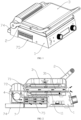
FIG. 1 is a schematic structural diagram of a smokeless frying and baking machine according toEmbodiment 1 of the present disclosure when combining trays. -
FIG. 2 is a first cross-sectional view of a smokeless frying and baking machine according toEmbodiment 1 of the present disclosure when combining trays. -
FIG. 3 is a second cross-sectional view of a smokeless frying and baking machine according toEmbodiment 1 of the present disclosure when combining trays. -
FIG. 4 is a schematic structural diagram of a smokeless frying and baking machine according toEmbodiment 1 of the present disclosure when unfolding the tray. -
FIG. 5 is a schematic structural diagram of a smokeless frying and baking machine according toEmbodiment 1 of the present disclosure when unfolding the tray. -
FIG. 6 is a schematic structural diagram of an exhaust component according toEmbodiment 1 of the present disclosure. -
FIG. 7 is a schematic diagram of mounting an exhaust component according toEmbodiment 1 of the present disclosure. -
FIG. 8 is a schematic diagram of mounting an angle detection component according toEmbodiment 1 of the present disclosure. -
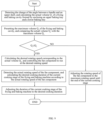
FIG. 9 is a flow chart of a control method of a smokeless frying and baking machine according toEmbodiment 2 of the present disclosure. - The specific meanings of the reference numbers are as follows:
- 1. Lower shell; 11. Lower baking tray; 2. Handle; 3. Upper shell; 31. Upper baking tray; 4. Fan component; 41. Variable-frequency motor; 42. Wind wheel; 5. Angle detection component; 6. Rotating speed detection component; 7. Air channel; 71. First air inlet; 72. Second air inlet; 73. Filter grille; 74. Oil receiving tray; 75. Filtered water box; 8. Oil baffle plate.
- The specific embodiments of the present disclosure will be described in detail in this section. The preferred embodiments of the present disclosure are shown in the attached drawings, which serves to supplement the description in the written part of the specification with figures, so that people can intuitively and vividly understand each technical feature and the overall technical scheme of the present d isclosure.
- In the description of the present disclosure, "a plurality of" means more than two, and "greater than, less than, more than, etc." are understood as excluding this number, and above, below, within, etc. are understood as including this number. If the first and second descriptions are only used for the purpose of distinguishing technical features, the descriptions cannot be understood as indicating or implying relative importance, implicitly indicating the number of indicated technical features, or implicitly indicating the sequence of indicated technical features.
- In the description of the present disclosure, it should be understood that for the orientational description, the orientational or positional relationships indicated by the terms such as "up", "down", "front", "back", "left" and "right" are based on the orientational or positional relationships shown in the drawings only for the convenience of describing the present disclosure and simplifying the description, rather than indicate or imply that the referred devices or elements must have a specific orientation, be constructed and operated in a specific orientation.
- In the present disclosure, unless otherwise defined expressly, the terms such as "provide", "mount" and "connect" should be understood broadly, for example, it can be direct connection or indirect connection through an intermediate medium; fixed connection, detachable connection or integral connection; mechanical connection; or the internal communication of two elements or the interaction between two elements. Those skilled in the art can reasonably determine the specific meaning of the above terms in the present disclosure in combination with the specific content of the technical scheme.
- Referring to
FIGS. 1-8 ,Embodiment 1 of the present disclosure is provided, which discloses a smokeless frying and baking machine, comprising: - a
lower shell 1, which is provided with alower baking tray 11; - a
handle 2, which is rotatably mounted on thelower shell 1; - an
upper shell 3, which is provided with anupper baking tray 31, wherein theupper shell 3 is rotatably mounted on thehandle 2 through a floating component, and thehandle 2 is configured to drive theupper shell 3 to rotate back and forth to be close to thelower shell 1 so that theupper baking tray 31 and thelower baking tray 11 are enclosed to form a frying and baking cavity or rotate away from thelower shell 1 to the position of unfolding the tray; - a
fan component 4, wherein thelower shell 1 is provided with an air channel 7, thefan component 4 is mounted on thelower shell 1 and is configured to generate negative pressure in the air channel 7 to suck oil smoke generated by thelower baking tray 11 and theupper baking tray 31, - an
angle detection component 5, wherein theangle detection component 5 is mounted between thehandle 2 and theupper shell 3 and is configured to detect the change of the angle between thehandle 2 and theupper shell 3; - a rotating speed detection component 6, wherein the rotating speed detection component 6 is mounted on the
fan component 4 and is configured to detect the actual rotating speed of thefan component 4; - a controller, which is mounted on the
lower shell 1 and is electrically connected with thefan component 4, theangle detection component 5 and the rotating speed detection component 6, respectively, wherein the controller is configured to calculate the actual volume of the frying and baking cavity according to the angle change, when the actual volume is less than the maximum volume, control the rotating speed of thefan component 4 according to the desired rotating speed calculated by the actual volume, and then calculate the desired cooking duration of the current cooking stage of the frying and baking machine according to the actual rotating speed. - The controller is configured to receive the change of the angle between the
handle 2 and theupper shell 3, calculate the actual volume of the frying and baking cavity according to the angle change, compare the actual volume with the maximum volume, if the actual volume is less than or equal to the maximum volume, calculate the desired rotating speed corresponding to the actual volume, and control thefan component 4 to run at the desired rotating speed. The controller receives the actual rotating speed detected by the rotating speed detection component 6, calculates the desired cooking duration of the current cooking stage of the frying and baking machine according to the actual rotating speed of the fan component, and adjusts the duration of the current cooking stage of the frying and baking machine as the desired cooking duration; and if the actual volume is greater than the maximum volume, adjusts the rotating speed of the fan component to the maximum rotating speed until the end of the current cooking stage. - The working principle of the smokeless frying and baking machine in this embodiment is as follows.
- When the
upper shell 3 rotates to the position of combining the tray or unfolding the tray close to thelower shell 1, thefan component 4 generates negative pressure in the air channel 7, so that the oil smoke generated on theupper baking tray 31 and thelower baking tray 11 is sucked and discharged from the air channel 7. - After the food is placed on the
lower baking tray 11, after theupper shell 3 is rotated to combine the tray with thelower shell 1, theangle detection component 5 detects the change of the angle between thehandle 2 and theupper shell 3 and sends the change to the controller. According to the change of the angle between thehandle 2 and theupper shell 3, the actual volume of the frying and baking cavity is calculated, and the desired rotating speed of thefan component 4 is calculated. The controller then sends a signal to thefan component 4 to adjust the rotating speed of thefan component 4. Therefore, the rotating speed of thefan component 4 is regulated according to the size of the frying and baking cavity, so as to ensure the kitchen ventilator effect of the frying and baking machine. Meanwhile, the rotating speed detection component 6 detects the actual rotating speed of thefan component 4. The controller compensates for the cooking duration of the current cooking stage according to the desired actual rotating speed of thefan component 4, so as to prevent the fast air flow speed from affecting cooking and ensure the cooking effect of the frying and baking machine. The rotating speed detection component 6 can detect the actual rotating speed of thefan component 4, so as to prevent the calculation error of the desired cooking duration caused by the difference between the actual rotating speed of thefan component 4 and the desired rotating speed, and ensure the cooking effect of the frying and baking machine. - For example, the desired rotating speed of the
fan component 4 is 2000r/min, and the actual rotating speed of thefan component 4 detected by the rotating speed detection component 6 is 1900r/min, so that the calculation of the desired cooking duration can be more accurate by compensating for the cooking duration with the actual rotating speed. - The floating component is used to keep the
upper baking tray 31 horizontal. Thehandle 2 is mounted on theupper shell 3 by a floating component to keep horizontal, which belongs to the conventional technology in the field. The structure of the floating component is not specifically defined in the present disclosure. - Specifically, the
angle detection component 5 is an angle sensor. One end of the rotating shaft is connected with the floating component. The angle sensor is mounted at the other end of the rotating shaft. Moreover, the angle sensor is provided with an inner ring and an outer ring which can rotate relatively. The inner ring is coaxially and fixedly connected with the rotating shaft, and the outer ring is fixedly connected with the handle. The angle sensor is configured to detect the change of the angle between the inner ring and the outer ring and send the corresponding resistance change value ΔR to the controller, so that the controller calculates the volume of the frying and baking cavity according to the resistance change value ΔR. - Preferably, the air channel 7 is provided with two air inlets, and the two air inlets are distributed on one side of the
lower shell 1 close to and far away from the frying and baking cavity. - When the
upper shell 3 is in the position of unfolding the tray, the two air inlets are distributed between theupper tray 31 and thelower tray 11, which is suitable for the kitchen ventilator when the frying and baking machine is in the position of combining the tray and unfolding the tray. - More specifically, the two air inlets comprise a
first air inlet 71 and asecond air inlet 72, respectively, and when thefirst air inlet 71 is located above thelower baking tray 11 and theupper baking tray 31 is distributed in the position of unfolding the tray, thesecond air inlet 72 is located above theupper baking tray 31. - When the
first air inlet 71 is located above thelower baking tray 11, or thesecond air inlet 72 is distributed above theupper baking tray 31 in the position of unfolding the tray, thefirst air inlet 71 or thesecond air inlet 72 has a better suction effect on the oil smoke generated on theupper baking tray 31 and thelower baking tray 11. - On the basis of the above, the frying and baking machine further comprises a
filter grille 73. Thefilter grille 73 is mounted on thelower shell 1 and is located at the entrance of the air channel 7. Thefilter grille 73 is provided with ventilation holes penetrating therethrough, and the ventilation holes form the air inlet. - As shown in the figures, the front side and the rear side of the
filter grille 73 are provided with ventilation holes, respectively, and the ventilation holes on the front side and the rear side form thefirst air inlet 71 and thesecond air inlet 72, respectively. - The
filter grille 73 can preliminarily filter the steam and oil mist in the oil smoke. - Preferably, the smokeless frying and baking machine further comprises a filtered
water box 75, the filteredwater box 75 is provided with an air intake and an air vent communicated with the inside thereof, the filteredwater box 75 is provided at the outlet of the air channel 7 and is communicated with the air channel 7 through the air intake, and the air vent is communicated with the outside. As shown inFIG. 7 , air vents are provided on both side walls of the filtered water box, and the upper end of the filtered water box is provided with a notch to form an air intake. - The oil smoke in the air channel 7 is filtered by the water surface in the filtered
water box 75 and then is discharged from thelower shell 1, so that the oil smoke and water vapor are discharged after double filtration, which greatly reduces the harm of oil smoke and the like to human health, and reduces the secondary pollution caused by circulating air to food materials because the air channel 7 is not designed as a circulating air channel 7. - Preferably, the rotating speed detection component 6 comprises a speed measuring sensor, the speed measuring sensor is a Hall sensor or a photoelectric sensor, the
fan component 4 comprises a variable-frequency motor 41 and awind wheel 42 mounted at the output end of the variable-frequency motor 41, the rotating speed detection component 6 is mounted on thewind wheel 42 and is configured to detect the rotating speed of thewind wheel 42, and the variable-frequency motor 41 and the rotating speed detection component 6 are electrically connected with the controller, respectively. - The rotating speed measuring sensor is configured to detect the rotating speed of the
wind wheel 42 and send the rotating speed to the controller. The controller controls the variable-frequency motor 41 according to the real-time rotating speed of thewind wheel 42, so that the rotating speed of thewind wheel 42 can accurately reach the set rotating speed. - On the basis of the above, the smokeless frying and baking machine further comprises an
oil receiving tray 74, wherein the air channel 7 is provided with an oil leakage hole on a side wall below thefan component 4, and theoil receiving tray 74 is mounted on thelower shell 1 and is located below the oil leakage hole. - The
oil receiving tray 74 is provided below the fan, which is convenient to collect and clean oils and fats. - Preferably, the smokeless frying and baking machine further comprises two oil baffle plates 8, and the two oil baffle plates 8 are detachably provided on both sides of the
lower shell 1. Specifically, the oil baffle plates 8 are in magnetic adsorption connection with thelower shell 1, preventing a large amount of oil from splashing on the table top. It is convenient to disassemble and wash the magnetically attracted oil baffle plate 8. - The
fan component 4, thefilter grille 73, theoil receiving tray 74 and the filteredwater box 75 are detachably mounted on thelower shell 1, which is convenient to clean. - As shown in
FIG. 9 , based on the smokeless frying and baking machine disclosed inEmbodiment 1, a control method thereof is proposed, specifically comprising: -
Step 1, detecting the change of the angle between a handle and an upper shell, and calculating the actual volume Q1 of a frying and baking cavity formed by enclosing an upper baking tray and a lower baking tray; -
Step 2, presetting the maximum volume Q2 of the frying and baking cavity, and comparing the actual volume Q1 with the maximum volume Q2; - if the actual volume Q1 is less than or equal to the maximum volume Q2, calculating the desired rotating speed corresponding to the actual volume, and controlling the fan component to run at the desired rotating speed;
- calculating the desired rotating speed V with the formula: V = V0+Q1 * ΔV, where V0 is the preset rotating speed in the current cooking stage, and ΔV is the preset speed variable that varies with the volume of the frying and baking cavity;
- detecting the actual rotating speed V' of the fan component, and calculating the desired cooking duration of the current cooking stage of the frying and baking machine according to the actual rotating speed V' of the fan component;
- calculating the desired cooking duration T with the formula: T = T0+ V' * ΔT, where T0 is the preset cooking duration of the current cooking stage, and ΔT is the preset time variable that varies with the volume of the frying and baking cavity;
- adjusting the duration of the current cooking stage of the frying and baking machine to the desired cooking duration;
- if the actual volume Q1 is greater than the maximum volume Q2, adjusting the rotating speed of the fan component to the maximum rotating speed until the end of the current cooking stage.
- The actual volume Q1 of the frying and baking cavity enclosed by the
upper baking tray 31 and thelower baking tray 11 is calculated with the formula:

where a is the length of a baking tray, b is the width of a baking tray, ΔR is the resistance change value detected by an angle sensor, and m is a quantitative coefficient. - In this embodiment, the maximum rotating speed Vmax of the fan component is calculated with the formula:

Claims (10)
- A smokeless frying and baking machine, comprising:a lower shell (1), which is provided with a lower baking tray (11);a handle (2), which is rotatably mounted on the lower shell (1);an upper shell (3), which is provided with an upper baking tray (31), wherein the upper shell (3) is rotatably mounted on the handle (2) through a floating component, and the handle (2) is configured to drive the upper shell (3) to rotate back and forth to be close to the lower shell (1) so that the upper baking tray (31) and the lower baking tray (11) are enclosed to form a frying and baking cavity or rotate away from the lower shell (1) to the position of unfolding the tray;a fan component (4), wherein the lower shell (1) is provided with an air channel (7), the fan component (4) is mounted on the lower shell (1) and is configured to generate negative pressure in the air channel (7) to suck oil smoke generated by the lower baking tray (11) and the upper baking tray (31),an angle detection component (5), wherein the angle detection component (5) is mounted between the handle (2) and the upper shell (3) and is configured to detect the change of the angle between the handle (2) and the upper shell (3);, characterised in:a rotating speed detection component (6), wherein the rotating speed detection component (6) is mounted on the fan component (4) and is configured to detect the actual rotating speed of the fan component (4);a controller, which is mounted on the lower shell (1) and is electrically connected with the fan component (4), the angle detection component (5) and the rotating speed detection component (6), respectively, wherein the controller is configured to calculate the actual volume of the frying and baking cavity according to the angle change, when the actual volume is less than the maximum volume, control the rotating speed of the fan component (4) according to the desired rotating speed calculated by the actual volume, and then calculate the desired cooking duration of the current cooking stage of the frying and baking machine according to the actual rotating speed.
- The smokeless frying and baking machine according to claim 1, wherein the air channel (7) is provided with two air inlets, and the two air inlets are both provided at the rear side of the lower shell (1) and are distributed at intervals from front to back.
- The smokeless frying and baking machine according to claim 2, wherein the two air inlets comprise a first air inlet (71) and a second air inlet (72), respectively, and when the first air inlet (71) is located above the lower baking tray (11) and the upper baking tray (31) is distributed in the position of unfolding the tray, the second air inlet (72) is located above the upper baking tray (31).
- The smokeless frying and baking machine according to claim 1, further comprising a filtered water box (75), wherein the filtered water box (75) is provided with an air intake and an air vent communicated with the inside thereof, the filtered water box (75) is provided at the outlet of the air channel (7) and is communicated with the air channel (7) through the air intake, and the air vent is communicated with the outside.
- The smokeless frying and baking machine according to claim 1, wherein the rotating speed detection component (6) comprises a speed measuring sensor, the speed measuring sensor is a Hall sensor or a photoelectric sensor, the fan component (4) comprises a motor (41) and a wind wheel (42) mounted at the output end of the motor (41), the rotating speed detection component (6) is mounted on the wind wheel (42) and is configured to detect the rotating speed of the wind wheel (42), and the motor (41) and the rotating speed detection component (6) are electrically connected with the controller, respectively.
- The smokeless frying and baking machine according to claim 1, further comprising an oil receiving tray (74), wherein the air channel (7) is provided with an oil leakage hole on a side wall below the fan component (4), and the oil receiving tray (74) is mounted on the lower shell (1) and is located below the oil leakage hole.
- The smokeless frying and baking machine according to claim 1, further comprising two oil baffle plates (8), and the two oil baffle plates (8) are detachably provided on both sides of the lower shell (1).
- The smokeless frying and baking machine according to claim 7, wherein the oil baffle plates (8) are in magnetic adsorption connection with the lower shell (1).
- A control method of the smokeless frying and baking machine according to claim 1, comprising the following steps:Step 1, detecting the change of the angle between a handle and an upper shell, and calculating the actual volume Q1 of a frying and baking cavity formed by enclosing an upper baking tray and a lower baking tray;Step 2, presetting the maximum volume Q2 of the frying and baking cavity, and comparing the actual volume Q1 with the maximum volume Q2;if the actual volume Q1 is less than or equal to the maximum volume Q2, calculating the desired rotating speed corresponding to the actual volume, and controlling the fan component to run at the desired rotating speed;calculating the desired rotating speed V with the formula: V = V0+Q1 * ΔV, where V0 is the preset rotating speed in the current cooking stage, and ΔV is the preset speed variable that varies with the volume of the frying and baking cavity;detecting the actual rotating speed V' of the fan component, and calculating the desired cooking duration of the current cooking stage of the frying and baking machine according to the actual rotating speed V' of the fan component;calculating the desired cooking duration T with the formula: T = T0+ V' * ΔT, where T0 is the preset cooking duration of the current cooking stage, and ΔT is the preset time variable that varies with the volume of the frying and baking cavity;adjusting the duration of the current cooking stage of the frying and baking machine to the desired cooking duration;if the actual volume Q1 is greater than the maximum volume Q2, adjusting the rotating speed of the fan component to the maximum rotating speed until the end of the current cooking stage.
- The control method of the smokeless frying and baking machine according to claim 9, comprising the following steps:calculating the actual volume Q1 of the frying and baking cavity enclosed by the upper baking tray and the lower baking tray with the formula:
 where a is the length of a baking tray, b is the width of a baking tray, ΔR is the resistance change value detected by an angle sensor, and m is a quantitative coefficient.
Applications Claiming Priority (2)
| Application Number | Priority Date | Filing Date | Title |
|---|---|---|---|
| CN202210394005.1A CN114831518B (en) | 2022-04-15 | 2022-04-15 | Smokeless frying and baking machine and control method thereof |
| PCT/CN2022/087714 WO2023197343A1 (en) | 2022-04-15 | 2022-04-19 | Smokeless frying and baking machine and control method therefor |
Publications (3)
| Publication Number | Publication Date |
|---|---|
| EP4338645A1 EP4338645A1 (en) | 2024-03-20 |
| EP4338645A4 EP4338645A4 (en) | 2024-07-24 |
| EP4338645B1 true EP4338645B1 (en) | 2025-03-19 |
Family
ID=82565581
Family Applications (1)
| Application Number | Title | Priority Date | Filing Date |
|---|---|---|---|
| EP22936988.9A Active EP4338645B1 (en) | 2022-04-15 | 2022-04-19 | Smokeless frying and baking machine and control method therefor |
Country Status (6)
| Country | Link |
|---|---|
| US (1) | US12564287B2 (en) |
| EP (1) | EP4338645B1 (en) |
| KR (1) | KR20230148321A (en) |
| CN (1) | CN114831518B (en) |
| ES (1) | ES3020008T3 (en) |
| WO (1) | WO2023197343A1 (en) |
Families Citing this family (1)
| Publication number | Priority date | Publication date | Assignee | Title |
|---|---|---|---|---|
| CN116998917A (en) * | 2023-06-29 | 2023-11-07 | 宁波兰花电器制造有限公司 | A kind of grill and grill pan control method |
Family Cites Families (37)
| Publication number | Priority date | Publication date | Assignee | Title |
|---|---|---|---|---|
| JPH0199207A (en) * | 1987-10-13 | 1989-04-18 | Mitsubishi Mining & Cement Co Ltd | Capacitor structure |
| US6369366B1 (en) * | 1999-06-03 | 2002-04-09 | Charles F. Mullen | Portable DC and AC electric cooking apparatus |
| JP2001190425A (en) * | 2000-01-11 | 2001-07-17 | Matsushita Electric Ind Co Ltd | Cooking device |
| US6608292B1 (en) * | 2002-07-26 | 2003-08-19 | Neal Patrick Barnes | Microwave grilling appliance |
| US7946224B2 (en) * | 2003-07-07 | 2011-05-24 | Turbochef Technologies, Inc. | Griddle |
| CN201469035U (en) * | 2009-06-17 | 2010-05-19 | 漳州灿坤实业有限公司 | Two-way start frying and roasting device |
| FR2985650B1 (en) * | 2012-01-16 | 2016-03-11 | Seb Sa | FOOD COOKING INFORMATION METHOD AND ASSOCIATED APPARATUS |
| FR2985649B1 (en) * | 2012-01-16 | 2016-03-11 | Seb Sa | METHOD FOR COOKING FOOD AND APPARATUS USING THE SAME |
| US11219333B2 (en) * | 2013-08-02 | 2022-01-11 | Conair Llc | Wireless temperature sensing system for a cooking appliance |
| US10130205B2 (en) * | 2013-08-02 | 2018-11-20 | Conair Corporation | Temperature sensing system for a cooking appliance |
| US10898029B2 (en) * | 2013-08-02 | 2021-01-26 | Conair Corporation | Smoke reduction system for a cooking appliance |
| US9474412B2 (en) * | 2013-08-05 | 2016-10-25 | Conair Corporation | Smoke filter system for a cooking appliance |
| US9433319B2 (en) * | 2013-08-05 | 2016-09-06 | Conair Corporation | Splash guard for a cooking appliance |
| US9636618B2 (en) * | 2013-08-05 | 2017-05-02 | Conair Corporation | Smoke exhaust system for a cooking appliance |
| CN107072440B (en) * | 2014-03-14 | 2019-10-22 | 斯派克初姆布兰斯有限公司 | Wireless Operable Cooking Appliances |
| CN105310523B (en) * | 2014-06-23 | 2017-09-22 | 漳州灿坤实业有限公司 | The cooked device of food |
| US20160113438A1 (en) * | 2014-10-23 | 2016-04-28 | Value Added Services & Technology, Inc. | System and method for customized control and monitoring of commercial kitchen equipment |
| CN106264192B (en) * | 2015-06-12 | 2018-11-16 | 漳州灿坤实业有限公司 | Vertical draining type grillING device |
| US11229314B2 (en) * | 2016-06-28 | 2022-01-25 | Cook Tek Induction Systems, Llc | Clamshell induction cooking system |
| CN206714645U (en) * | 2016-12-12 | 2017-12-08 | 漳州灿坤实业有限公司 | Low oil smoke grill |
| CN206572597U (en) * | 2017-03-28 | 2017-10-20 | 广东百晟图电器实业有限公司 | A kind of grill that may filter that oil smoke |
| CN207666471U (en) * | 2017-04-12 | 2018-07-31 | 广东百晟图电器实业有限公司 | A kind of grill with food weight and thickness identification function |
| CN208524648U (en) * | 2017-06-19 | 2019-02-22 | 广东百胜图科技有限公司 | A kind of grill of adjustable heated condition |
| CN208510800U (en) * | 2017-08-31 | 2019-02-19 | 浙江苏泊尔家电制造有限公司 | Baking machine |
| CN107752796A (en) * | 2017-11-30 | 2018-03-06 | 贵州齐丰科技有限公司 | A kind of self-service smokeless roaster |
| CN109998388B (en) * | 2018-01-04 | 2024-06-04 | 漳州灿坤实业有限公司 | Grill that can direct oil smoke |
| US11013366B2 (en) * | 2018-01-04 | 2021-05-25 | Tsann Kuen (Zhangzhou) Enterprise Co., Ltd. | Grill device with a fume collecting chamber |
| AU2019355539A1 (en) * | 2018-10-04 | 2021-05-20 | Spectrum Brands, Inc. | Contact grill with passive smoke reduction |
| CN111035268A (en) * | 2018-10-14 | 2020-04-21 | 广东万事泰电器有限公司 | electric grill |
| CN109259617A (en) * | 2018-11-07 | 2019-01-25 | 陆流 | A kind of novel smokeless oven |
| CN210069993U (en) * | 2019-06-24 | 2020-02-14 | 广东新宝电器股份有限公司 | Frying and roasting equipment with oil smoke filtering structure |
| CN213605914U (en) * | 2020-07-24 | 2021-07-06 | 上海达显智能科技有限公司 | Intelligent frying and baking machine |
| CN112220332A (en) * | 2020-10-10 | 2021-01-15 | 广东美的厨房电器制造有限公司 | Cooking equipment, control method and device for cooking equipment |
| US11051651B1 (en) * | 2020-10-29 | 2021-07-06 | Tristar Products, Inc. | Indoor smokeless grill |
| CN216020557U (en) * | 2021-03-31 | 2022-03-15 | 宁波先锋电器制造有限公司 | Smokeless baking equipment with novel air channel |
| CN215077701U (en) * | 2021-04-20 | 2021-12-10 | 广东新宝电器股份有限公司 | Micro-smoke frying and roasting device |
| CN113180494A (en) * | 2021-06-03 | 2021-07-30 | 厦门怡星智能科技有限公司 | Novel smokeless frying and roasting equipment |
-
2022
- 2022-04-15 CN CN202210394005.1A patent/CN114831518B/en active Active
- 2022-04-19 KR KR1020237021021A patent/KR20230148321A/en not_active Ceased
- 2022-04-19 ES ES22936988T patent/ES3020008T3/en active Active
- 2022-04-19 WO PCT/CN2022/087714 patent/WO2023197343A1/en not_active Ceased
- 2022-04-19 EP EP22936988.9A patent/EP4338645B1/en active Active
- 2022-11-15 US US17/987,069 patent/US12564287B2/en active Active
Also Published As
| Publication number | Publication date |
|---|---|
| CN114831518B (en) | 2023-10-20 |
| WO2023197343A1 (en) | 2023-10-19 |
| CN114831518A (en) | 2022-08-02 |
| EP4338645A1 (en) | 2024-03-20 |
| US20230329480A1 (en) | 2023-10-19 |
| ES3020008T3 (en) | 2025-05-21 |
| KR20230148321A (en) | 2023-10-24 |
| US12564287B2 (en) | 2026-03-03 |
| EP4338645A4 (en) | 2024-07-24 |
Similar Documents
| Publication | Publication Date | Title |
|---|---|---|
| CN112050270B (en) | Control method of range hood | |
| CN103807897B (en) | Multiple spot point sucking kitchen ventilator and its control method | |
| WO2021184864A1 (en) | Range hood and control method therefor | |
| CN111322648B (en) | Control method of cooking device | |
| CN111578333B (en) | Control method of cooking device | |
| CN111336557B (en) | Range hood and control method thereof | |
| CN112254188B (en) | Control method of cooking device | |
| EP4338645A1 (en) | Smokeless frying and baking machine and control method therefor | |
| CN113108346A (en) | Speed regulation control method for preventing smoke leakage of range hood | |
| CN209445447U (en) | Air inlet adjustable range hood | |
| CN113719871A (en) | Range hood and control method thereof | |
| CN206959055U (en) | A kind of range hood of adjustable suction effect | |
| CN113237107A (en) | Control method of cooking device | |
| CN210069993U (en) | Frying and roasting equipment with oil smoke filtering structure | |
| CN113639291B (en) | Range hood and control method thereof | |
| CN113685862A (en) | Range hood and control method thereof | |
| CN113108347B (en) | Side-wind prevention control method for range hood | |
| CN113639292B (en) | Range hood and control method thereof | |
| CN210993562U (en) | Cast iron overware oil smoke processing apparatus | |
| CN110715335B (en) | Range hood and control method thereof | |
| CN115568770A (en) | Intelligent heating control method, device, equipment and medium for oven | |
| CN116147035A (en) | Flow distribution device and flow distribution method for range hood | |
| CN113983504A (en) | Range hood and control method thereof | |
| CN114396641A (en) | Integrated cooker and control method thereof | |
| CN113685865A (en) | Range hood and control method thereof |
Legal Events
| Date | Code | Title | Description |
|---|---|---|---|
| STAA | Information on the status of an ep patent application or granted ep patent |
Free format text: STATUS: THE INTERNATIONAL PUBLICATION HAS BEEN MADE |
|
| PUAI | Public reference made under article 153(3) epc to a published international application that has entered the european phase |
Free format text: ORIGINAL CODE: 0009012 |
|
| STAA | Information on the status of an ep patent application or granted ep patent |
Free format text: STATUS: REQUEST FOR EXAMINATION WAS MADE |
|
| 17P | Request for examination filed |
Effective date: 20231214 |
|
| AK | Designated contracting states |
Kind code of ref document: A1 Designated state(s): AL AT BE BG CH CY CZ DE DK EE ES FI FR GB GR HR HU IE IS IT LI LT LU LV MC MK MT NL NO PL PT RO RS SE SI SK SM TR |
|
| A4 | Supplementary search report drawn up and despatched |
Effective date: 20240624 |
|
| RIC1 | Information provided on ipc code assigned before grant |
Ipc: A47J 36/32 20060101ALI20240618BHEP Ipc: A47J 37/10 20060101ALI20240618BHEP Ipc: A47J 37/06 20060101AFI20240618BHEP |
|
| GRAP | Despatch of communication of intention to grant a patent |
Free format text: ORIGINAL CODE: EPIDOSNIGR1 |
|
| STAA | Information on the status of an ep patent application or granted ep patent |
Free format text: STATUS: GRANT OF PATENT IS INTENDED |
|
| DAV | Request for validation of the european patent (deleted) | ||
| DAX | Request for extension of the european patent (deleted) | ||
| INTG | Intention to grant announced |
Effective date: 20241213 |
|
| GRAS | Grant fee paid |
Free format text: ORIGINAL CODE: EPIDOSNIGR3 |
|
| GRAA | (expected) grant |
Free format text: ORIGINAL CODE: 0009210 |
|
| STAA | Information on the status of an ep patent application or granted ep patent |
Free format text: STATUS: THE PATENT HAS BEEN GRANTED |
|
| AK | Designated contracting states |
Kind code of ref document: B1 Designated state(s): AL AT BE BG CH CY CZ DE DK EE ES FI FR GB GR HR HU IE IS IT LI LT LU LV MC MK MT NL NO PL PT RO RS SE SI SK SM TR |
|
| REG | Reference to a national code |
Ref country code: GB Ref legal event code: FG4D |
|
| REG | Reference to a national code |
Ref country code: CH Ref legal event code: EP |
|
| REG | Reference to a national code |
Ref country code: IE Ref legal event code: FG4D |
|
| REG | Reference to a national code |
Ref country code: DE Ref legal event code: R096 Ref document number: 602022012081 Country of ref document: DE |
|
| REG | Reference to a national code |
Ref country code: ES Ref legal event code: FG2A Ref document number: 3020008 Country of ref document: ES Kind code of ref document: T3 Effective date: 20250521 |
|
| PG25 | Lapsed in a contracting state [announced via postgrant information from national office to epo] |
Ref country code: RS Free format text: LAPSE BECAUSE OF FAILURE TO SUBMIT A TRANSLATION OF THE DESCRIPTION OR TO PAY THE FEE WITHIN THE PRESCRIBED TIME-LIMIT Effective date: 20250619 |
|
| PG25 | Lapsed in a contracting state [announced via postgrant information from national office to epo] |
Ref country code: FI Free format text: LAPSE BECAUSE OF FAILURE TO SUBMIT A TRANSLATION OF THE DESCRIPTION OR TO PAY THE FEE WITHIN THE PRESCRIBED TIME-LIMIT Effective date: 20250319 |
|
| REG | Reference to a national code |
Ref country code: LT Ref legal event code: MG9D |
|
| PG25 | Lapsed in a contracting state [announced via postgrant information from national office to epo] |
Ref country code: NO Free format text: LAPSE BECAUSE OF FAILURE TO SUBMIT A TRANSLATION OF THE DESCRIPTION OR TO PAY THE FEE WITHIN THE PRESCRIBED TIME-LIMIT Effective date: 20250619 |
|
| PG25 | Lapsed in a contracting state [announced via postgrant information from national office to epo] |
Ref country code: HR Free format text: LAPSE BECAUSE OF FAILURE TO SUBMIT A TRANSLATION OF THE DESCRIPTION OR TO PAY THE FEE WITHIN THE PRESCRIBED TIME-LIMIT Effective date: 20250319 |
|
| PG25 | Lapsed in a contracting state [announced via postgrant information from national office to epo] |
Ref country code: LV Free format text: LAPSE BECAUSE OF FAILURE TO SUBMIT A TRANSLATION OF THE DESCRIPTION OR TO PAY THE FEE WITHIN THE PRESCRIBED TIME-LIMIT Effective date: 20250319 |
|
| PG25 | Lapsed in a contracting state [announced via postgrant information from national office to epo] |
Ref country code: BG Free format text: LAPSE BECAUSE OF FAILURE TO SUBMIT A TRANSLATION OF THE DESCRIPTION OR TO PAY THE FEE WITHIN THE PRESCRIBED TIME-LIMIT Effective date: 20250319 Ref country code: GR Free format text: LAPSE BECAUSE OF FAILURE TO SUBMIT A TRANSLATION OF THE DESCRIPTION OR TO PAY THE FEE WITHIN THE PRESCRIBED TIME-LIMIT Effective date: 20250620 |
|
| REG | Reference to a national code |
Ref country code: AT Ref legal event code: MK05 Ref document number: 1776212 Country of ref document: AT Kind code of ref document: T Effective date: 20250319 |
|
| PG25 | Lapsed in a contracting state [announced via postgrant information from national office to epo] |
Ref country code: NL Free format text: LAPSE BECAUSE OF FAILURE TO SUBMIT A TRANSLATION OF THE DESCRIPTION OR TO PAY THE FEE WITHIN THE PRESCRIBED TIME-LIMIT Effective date: 20250319 |
|
| PG25 | Lapsed in a contracting state [announced via postgrant information from national office to epo] |
Ref country code: SE Free format text: LAPSE BECAUSE OF FAILURE TO SUBMIT A TRANSLATION OF THE DESCRIPTION OR TO PAY THE FEE WITHIN THE PRESCRIBED TIME-LIMIT Effective date: 20250319 |
|
| PG25 | Lapsed in a contracting state [announced via postgrant information from national office to epo] |
Ref country code: SM Free format text: LAPSE BECAUSE OF FAILURE TO SUBMIT A TRANSLATION OF THE DESCRIPTION OR TO PAY THE FEE WITHIN THE PRESCRIBED TIME-LIMIT Effective date: 20250319 |
|
| PG25 | Lapsed in a contracting state [announced via postgrant information from national office to epo] |
Ref country code: PT Free format text: LAPSE BECAUSE OF FAILURE TO SUBMIT A TRANSLATION OF THE DESCRIPTION OR TO PAY THE FEE WITHIN THE PRESCRIBED TIME-LIMIT Effective date: 20250721 |
|
| PG25 | Lapsed in a contracting state [announced via postgrant information from national office to epo] |
Ref country code: IT Free format text: LAPSE BECAUSE OF FAILURE TO SUBMIT A TRANSLATION OF THE DESCRIPTION OR TO PAY THE FEE WITHIN THE PRESCRIBED TIME-LIMIT Effective date: 20250319 Ref country code: PL Free format text: LAPSE BECAUSE OF FAILURE TO SUBMIT A TRANSLATION OF THE DESCRIPTION OR TO PAY THE FEE WITHIN THE PRESCRIBED TIME-LIMIT Effective date: 20250319 |
|
| PG25 | Lapsed in a contracting state [announced via postgrant information from national office to epo] |
Ref country code: AT Free format text: LAPSE BECAUSE OF FAILURE TO SUBMIT A TRANSLATION OF THE DESCRIPTION OR TO PAY THE FEE WITHIN THE PRESCRIBED TIME-LIMIT Effective date: 20250319 |
|
| PG25 | Lapsed in a contracting state [announced via postgrant information from national office to epo] |
Ref country code: EE Free format text: LAPSE BECAUSE OF FAILURE TO SUBMIT A TRANSLATION OF THE DESCRIPTION OR TO PAY THE FEE WITHIN THE PRESCRIBED TIME-LIMIT Effective date: 20250319 Ref country code: CZ Free format text: LAPSE BECAUSE OF FAILURE TO SUBMIT A TRANSLATION OF THE DESCRIPTION OR TO PAY THE FEE WITHIN THE PRESCRIBED TIME-LIMIT Effective date: 20250319 |
|
| PG25 | Lapsed in a contracting state [announced via postgrant information from national office to epo] |
Ref country code: RO Free format text: LAPSE BECAUSE OF FAILURE TO SUBMIT A TRANSLATION OF THE DESCRIPTION OR TO PAY THE FEE WITHIN THE PRESCRIBED TIME-LIMIT Effective date: 20250319 |
|
| PG25 | Lapsed in a contracting state [announced via postgrant information from national office to epo] |
Ref country code: SK Free format text: LAPSE BECAUSE OF FAILURE TO SUBMIT A TRANSLATION OF THE DESCRIPTION OR TO PAY THE FEE WITHIN THE PRESCRIBED TIME-LIMIT Effective date: 20250319 |
|
| PG25 | Lapsed in a contracting state [announced via postgrant information from national office to epo] |
Ref country code: IS Free format text: LAPSE BECAUSE OF FAILURE TO SUBMIT A TRANSLATION OF THE DESCRIPTION OR TO PAY THE FEE WITHIN THE PRESCRIBED TIME-LIMIT Effective date: 20250719 |
|
| REG | Reference to a national code |
Ref country code: CH Ref legal event code: H13 Free format text: ST27 STATUS EVENT CODE: U-0-0-H10-H13 (AS PROVIDED BY THE NATIONAL OFFICE) Effective date: 20251125 |
|
| PG25 | Lapsed in a contracting state [announced via postgrant information from national office to epo] |
Ref country code: LU Free format text: LAPSE BECAUSE OF NON-PAYMENT OF DUE FEES Effective date: 20250419 |
|
| PG25 | Lapsed in a contracting state [announced via postgrant information from national office to epo] |
Ref country code: MC Free format text: LAPSE BECAUSE OF FAILURE TO SUBMIT A TRANSLATION OF THE DESCRIPTION OR TO PAY THE FEE WITHIN THE PRESCRIBED TIME-LIMIT Effective date: 20250319 |
|
| REG | Reference to a national code |
Ref country code: DE Ref legal event code: R097 Ref document number: 602022012081 Country of ref document: DE |
|
| REG | Reference to a national code |
Ref country code: BE Ref legal event code: MM Effective date: 20250430 |
|
| PG25 | Lapsed in a contracting state [announced via postgrant information from national office to epo] |
Ref country code: DK Free format text: LAPSE BECAUSE OF FAILURE TO SUBMIT A TRANSLATION OF THE DESCRIPTION OR TO PAY THE FEE WITHIN THE PRESCRIBED TIME-LIMIT Effective date: 20250319 |
|
| PG25 | Lapsed in a contracting state [announced via postgrant information from national office to epo] |
Ref country code: BE Free format text: LAPSE BECAUSE OF NON-PAYMENT OF DUE FEES Effective date: 20250430 |
|
| PG25 | Lapsed in a contracting state [announced via postgrant information from national office to epo] |
Ref country code: CH Free format text: LAPSE BECAUSE OF NON-PAYMENT OF DUE FEES Effective date: 20250430 |
|
| PLBE | No opposition filed within time limit |
Free format text: ORIGINAL CODE: 0009261 |
|
| STAA | Information on the status of an ep patent application or granted ep patent |
Free format text: STATUS: NO OPPOSITION FILED WITHIN TIME LIMIT |
|
| REG | Reference to a national code |
Ref country code: CH Ref legal event code: L10 Free format text: ST27 STATUS EVENT CODE: U-0-0-L10-L00 (AS PROVIDED BY THE NATIONAL OFFICE) Effective date: 20260128 |
|
| 26N | No opposition filed |
Effective date: 20251222 |
|
| PG25 | Lapsed in a contracting state [announced via postgrant information from national office to epo] |
Ref country code: IE Free format text: LAPSE BECAUSE OF NON-PAYMENT OF DUE FEES Effective date: 20250419 |
|
| PGFP | Annual fee paid to national office [announced via postgrant information from national office to epo] |
Ref country code: FR Payment date: 20260316 Year of fee payment: 5 |
|
| PGFP | Annual fee paid to national office [announced via postgrant information from national office to epo] |
Ref country code: TR Payment date: 20260327 Year of fee payment: 5 |
|
| PG25 | Lapsed in a contracting state [announced via postgrant information from national office to epo] |
Ref country code: CY Free format text: LAPSE BECAUSE OF FAILURE TO SUBMIT A TRANSLATION OF THE DESCRIPTION OR TO PAY THE FEE WITHIN THE PRESCRIBED TIME-LIMIT Effective date: 20250319 |
|
| PG25 | Lapsed in a contracting state [announced via postgrant information from national office to epo] |
Ref country code: LT Free format text: LAPSE BECAUSE OF FAILURE TO SUBMIT A TRANSLATION OF THE DESCRIPTION OR TO PAY THE FEE WITHIN THE PRESCRIBED TIME-LIMIT Effective date: 20250319 |
|
| PGFP | Annual fee paid to national office [announced via postgrant information from national office to epo] |
Ref country code: ES Payment date: 20260513 Year of fee payment: 5 |
|
| PGFP | Annual fee paid to national office [announced via postgrant information from national office to epo] |
Ref country code: DE Payment date: 20260416 Year of fee payment: 5 |