EP4338568B1 - An einem bodenbearbeitungsmaschinenrahmen anschliessbares pflanzenschneidmodul und bodenbearbeitungsmaschine mit mindestens einem schneidmodul - Google Patents
An einem bodenbearbeitungsmaschinenrahmen anschliessbares pflanzenschneidmodul und bodenbearbeitungsmaschine mit mindestens einem schneidmodul Download PDFInfo
- Publication number
- EP4338568B1 EP4338568B1 EP23195221.9A EP23195221A EP4338568B1 EP 4338568 B1 EP4338568 B1 EP 4338568B1 EP 23195221 A EP23195221 A EP 23195221A EP 4338568 B1 EP4338568 B1 EP 4338568B1
- Authority
- EP
- European Patent Office
- Prior art keywords
- box
- discs
- disc
- cutting module
- chassis
- Prior art date
- Legal status (The legal status is an assumption and is not a legal conclusion. Google has not performed a legal analysis and makes no representation as to the accuracy of the status listed.)
- Active
Links
Images


Classifications
-
- A—HUMAN NECESSITIES
- A01—AGRICULTURE; FORESTRY; ANIMAL HUSBANDRY; HUNTING; TRAPPING; FISHING
- A01D—HARVESTING; MOWING
- A01D34/00—Mowers; Mowing apparatus of harvesters
- A01D34/01—Mowers; Mowing apparatus of harvesters characterised by features relating to the type of cutting apparatus
- A01D34/412—Mowers; Mowing apparatus of harvesters characterised by features relating to the type of cutting apparatus having rotating cutters
- A01D34/63—Mowers; Mowing apparatus of harvesters characterised by features relating to the type of cutting apparatus having rotating cutters having cutters rotating about a vertical axis
-
- A—HUMAN NECESSITIES
- A01—AGRICULTURE; FORESTRY; ANIMAL HUSBANDRY; HUNTING; TRAPPING; FISHING
- A01D—HARVESTING; MOWING
- A01D34/00—Mowers; Mowing apparatus of harvesters
- A01D34/01—Mowers; Mowing apparatus of harvesters characterised by features relating to the type of cutting apparatus
- A01D34/412—Mowers; Mowing apparatus of harvesters characterised by features relating to the type of cutting apparatus having rotating cutters
- A01D34/42—Mowers; Mowing apparatus of harvesters characterised by features relating to the type of cutting apparatus having rotating cutters having cutters rotating about a horizontal axis, e.g. cutting-cylinders
- A01D34/62—Other details
-
- A—HUMAN NECESSITIES
- A01—AGRICULTURE; FORESTRY; ANIMAL HUSBANDRY; HUNTING; TRAPPING; FISHING
- A01D—HARVESTING; MOWING
- A01D34/00—Mowers; Mowing apparatus of harvesters
- A01D34/01—Mowers; Mowing apparatus of harvesters characterised by features relating to the type of cutting apparatus
- A01D34/412—Mowers; Mowing apparatus of harvesters characterised by features relating to the type of cutting apparatus having rotating cutters
- A01D34/63—Mowers; Mowing apparatus of harvesters characterised by features relating to the type of cutting apparatus having rotating cutters having cutters rotating about a vertical axis
- A01D34/64—Mowers; Mowing apparatus of harvesters characterised by features relating to the type of cutting apparatus having rotating cutters having cutters rotating about a vertical axis mounted on a vehicle, e.g. a tractor, or drawn by an animal or a vehicle
- A01D34/66—Mowers; Mowing apparatus of harvesters characterised by features relating to the type of cutting apparatus having rotating cutters having cutters rotating about a vertical axis mounted on a vehicle, e.g. a tractor, or drawn by an animal or a vehicle with two or more cutters
- A01D34/664—Disc cutter bars
- A01D34/665—Disc cutter bars modular
-
- A—HUMAN NECESSITIES
- A01—AGRICULTURE; FORESTRY; ANIMAL HUSBANDRY; HUNTING; TRAPPING; FISHING
- A01D—HARVESTING; MOWING
- A01D34/00—Mowers; Mowing apparatus of harvesters
- A01D34/01—Mowers; Mowing apparatus of harvesters characterised by features relating to the type of cutting apparatus
- A01D34/412—Mowers; Mowing apparatus of harvesters characterised by features relating to the type of cutting apparatus having rotating cutters
- A01D34/63—Mowers; Mowing apparatus of harvesters characterised by features relating to the type of cutting apparatus having rotating cutters having cutters rotating about a vertical axis
- A01D34/73—Cutting apparatus
-
- A—HUMAN NECESSITIES
- A01—AGRICULTURE; FORESTRY; ANIMAL HUSBANDRY; HUNTING; TRAPPING; FISHING
- A01D—HARVESTING; MOWING
- A01D34/00—Mowers; Mowing apparatus of harvesters
- A01D34/01—Mowers; Mowing apparatus of harvesters characterised by features relating to the type of cutting apparatus
- A01D34/412—Mowers; Mowing apparatus of harvesters characterised by features relating to the type of cutting apparatus having rotating cutters
- A01D34/63—Mowers; Mowing apparatus of harvesters characterised by features relating to the type of cutting apparatus having rotating cutters having cutters rotating about a vertical axis
- A01D34/81—Casings; Housings
-
- A—HUMAN NECESSITIES
- A01—AGRICULTURE; FORESTRY; ANIMAL HUSBANDRY; HUNTING; TRAPPING; FISHING
- A01D—HARVESTING; MOWING
- A01D34/00—Mowers; Mowing apparatus of harvesters
- A01D34/835—Mowers; Mowing apparatus of harvesters specially adapted for particular purposes
Definitions
- the present invention relates to a plant cutting module coupleable to a soil working machine chassis and a soil working machine comprising at least one cutting module.
- a module for cutting plants called inter-row which can be coupled to a chassis of a soil working machine
- said cutting module comprising a box that can be positioned in support on the ground, at least one rotating cutting disc with a so-called vertical axis of rotation housed inside the box and a device for driving in rotation the at least one disc equipping said box, said box having, in the ground support use configuration, an open front face, an opposite rear face, side faces, a bottom face facing the soil to be worked and an opposite top face, and the so-called vertical axis of rotation of the at least one disc passing through the bottom and top faces of the box.
- Such a cutting module is known as illustrated in the document GB-1.257.702 .
- inter-row vegetation can be made up of grass intended to form a fertilizer or unwanted vegetation. In all cases, it is necessary to eliminate this vegetation which tends to develop.
- a rotary cutter has been used which forms a cutting device of the type described above.
- the box houses a single disc. The portions of plants resulting from cutting using a rotary cutter are very long so that it is necessary to collect them after cutting.
- such a rotary cutter requires significant power for its operation, requiring require the use of the power take-off of the vehicle towing the rotary mower or require a hydraulic unit when the rotary mower is towed.
- An aim of the invention is to propose a cutting module of the aforementioned type whose design allows fragmentation of plants without the cutting module requiring significant power for its operation.
- the invention relates to a plant cutting module that can be coupled to a soil working machine chassis, said cutting module comprising a box that can be positioned in support on the ground, at least one rotary cutting disc with a so-called vertical axis of rotation housed inside the box and a device for driving in rotation the at least one disc equipping said box, said box having in the ground support usage configuration, an open front face, an opposite rear face, side faces, a bottom face facing the soil to be worked and an opposite top face, and the so-called vertical axis of rotation of the at least one disc passing through the bottom and top faces of the box, characterized in that the number of cutting discs is at least equal to 4, in that the cutting discs mounted integral in rotation form at least two sets of discs arranged, seen from the front face of the box, side by side inside the box, in the configuration of use of the box with each set of discs comprising at least two superimposed parallel coaxial discs, in that the disks of one of the sets and the disks of the other or of another set
- the cutting module is more particularly intended for cutting plants extending between the rows of crops and called inter-row.
- the organization of the discs in the form of at least two sets of discs mounted integrally in rotation with each set comprising at least two discs makes it possible to fragment the plants with a reduced necessary power without harming the simplicity of the construction due to a solid mounting in rotation of the discs.
- the production of the discs in the form of discs with knives offset angularly from one disc to another with a possible retraction of the knives when encountering an obstacle and a deployment of the knives operating under the simple action of the centrifugal force resulting from the rotation of the discs makes it possible to obtain a module whose operation is safe and maintenance easy.
- the knives which are angularly offset from a disk of a set of disks to a coplanar disk of another set of disks are angularly offset by an angle substantially equal to 90° to within plus or minus 30°.
- each disc is a preferably smooth circular, ovoid or triangular disc.
- At least one, preferably each knife is formed of a rectangular blade of which at least two edges are sharp. This results, due to the possible variation in position of the knife, in increased efficiency of the knife.
- the device for driving the disks in rotation equipping said box comprises at least one motor, preferably hydraulic, extending in projection from the face of the top of the box and a mechanical system for transmitting the rotational movement of the motor to the disks.
- This mechanical transmission system may be a mechanical system with gears, chains, belts or other.
- the front face of the box is in the configuration of use of the box surmounted by a deflector.
- This deflector makes it possible to fold down the plants to facilitate the supply of plants to the front face.
- the bottom face and/or the side faces of the box are equipped with at least one ground support member, such as a ground support pad of the box.
- ground support member such as a ground support pad of the box.
- the invention also relates to a soil working machine for row cultivation comprising at least one chassis and at least one plant cutting module which can be coupled to the chassis, characterized in that the or at least one, preferably each of the cutting modules conforms to those described above.
- the chassis comprises at least one beam intended to extend transversely to the crop rows, the number of cutting modules is at least equal to two, and the cutting modules are coupleable in an axially offset manner along the beam.
- the chassis comprises at least one so-called transverse beam extending transversely to the direction of movement of the chassis.
- the cutting modules can be arranged one at one of the ends, the other at the other of the ends of the beam to extend on either side of a crop row with the beam spanning said row.
- the beam is a beam adjustable in length.
- the machine can adapt to any type of row crop.
- each cutting module is, in the coupled state to the chassis, connected to the chassis by a non-rigid connecting device to allow the box of the cutting module to follow the profile of the ground.
- a non-rigid connecting device i.e. allowing freedom of movement of the box, makes it possible to avoid damage to the box when the box encounters an obstacle during the advancement of the box along a row of crops.
- the connecting device comprises a plurality of flexible links, such as chains, each flexible link extends between a side face or the top face of the box and the chassis, and the links arranged closest to the front face are of shorter length than the links arranged closest to the rear face of the box.
- the bottom face The cutting module is inclined downward from the front face to the rear face, which facilitates its advancement.
- the invention relates to a cutting module 3 which can be coupled to a chassis 2 of a soil working machine 1 to enable a soil working machine 1 to be obtained, of the type of that represented at the figure 1 where here two cutting modules 3 have been coupled to the chassis 2 of the soil working machine 1.
- This soil working machine 1 is intended for row crops, as illustrated in the figure 1 where the row is here formed by a tunnel greenhouse.
- the soil working machine 1 has the function of allowing each cutting module 3 equipping the soil working machine 1 to treat more specifically an inter-row zone, that is to say an area between two crop rows, to eliminate by fragmentation the plants that may have developed in a desired or undesirable manner in this zone.
- the soil working machine 1 therefore moves along a crop row.
- the chassis 2 of the machine is a mobile chassis.
- the chassis 2 of the soil working machine 1 may be indifferently a towed, semi-towed, carried or self-propelled chassis, without departing from the scope of the invention.
- the chassis 2 is a chassis towed by a tractor vehicle, such as a straddle vehicle, not shown, this straddle vehicle traveling along the line formed by the row of crops.
- the chassis 2 therefore moves in a direction of advance parallel to the longitudinal axis of a crop row.
- the chassis 2 can take a large number of forms.
- the chassis 2 comprises a beam 18 intended to extend transversely to the crop row 21, that is to say transversely to the direction D of advance of the chassis 2, as illustrated in figure 1 , and the cutting modules 3 are axially offset coupleable along the beam 18.
- one cutting module 3 is arranged at one end of the beam 18 and the other cutting module 3 at the other end of the beam 18.
- the beam 18 extends above the crop row 21 and one of the cutting modules 3 extends on one side of the crop row 21 and the other of the cutting modules 3 extends on the other side of the crop row 21, so that in a single movement of the chassis 2 along a crop row, both longitudinal sides of the crop row are treated.
- the beam 18 is a beam adjustable in length.
- the beam can thus be a telescopic beam formed of beam sections mounted at sliding interlocking.
- the length of the beam 18 is adjusted according to the width of the row of crops to be covered.
- Each cutting module 3 which can be coupled to such a chassis 2 comprises a box 4, rotating cutting discs 5 with a so-called vertical axis of rotation housed inside the box 4, and a device 6 for driving the discs 5 in rotation equipping said box 4.
- the box 4 has at least one usage configuration in which it is at least partially supported on the ground.
- the box in the ground-support usage configuration, has an open front face 7, an opposite rear face 8, side faces 9 and a bottom face 10 facing the ground to be worked and an opposite top face 22 facing the sky, as illustrated in figure 1 .
- this module 3 for cutting plants along the crop row is carried out with the side faces 9 of the box 4 extending substantially parallel to the longitudinal axis of the chassis 2.
- the open front face 7 of the box 4 therefore forms the attack face of the box 4 during the movement of the chassis 2 along a crop row.
- Each disk 5 is a rotating disk mounted to rotate around a so-called vertical axis of rotation, that is to say passing through the faces of the bottom 10 and the top 22 of the box 4.
- a cutting module 3 comprises at least four disks mounted integrally in rotation. These disks 5 are driven in rotation at the same speed. The cutting disks 5 therefore rotate at the same speed.
- These cutting discs 5 mounted integrally in rotation form at least two sets 11 of discs arranged, seen from the front face 7 of the box 4, side by side inside the box 4 in the configuration of use of the box 4 with each set 11 of discs comprising at least two superimposed parallel coaxial discs 5.
- each set 11 of discs forms a cutting line during the advancement of the chassis 2 of the soil working machine 1 along a row of crops.
- the number of sets 11 of disks which is at least equal to two can be any number.
- the number of sets 11 of disks is equal to two to simplify the description.
- the number of disks 5 for a set 11 of disks is at least equal to two, but can be any number. Again, only two disks have been shown per set 11 with an upper disk and a lower disk to simplify the description.
- the disks 5 of one of the sets 11 of disks and the disks 5 of the other set 11 of disks are counter-rotating disks, that is to say rotating in opposite directions of rotation. These disks thus form between them a zone which makes it possible to drive the plants from the front face to the rear face of the box 4.
- Each disk 5 of a set 11 is coplanar with a disk 5 of the other set 11.
- the disk 5 called upper of one of the sets of disks is coplanar with the disk 5 called upper of the other set of disks.
- the lower disk 5 of one of the disk sets is coplanar with the so-called lower disk 5 of the other of the disk sets.
- each disk 5 is a smooth ovoid disk.
- the disk could also have been notched without departing from the scope of the invention.
- the disk could have been circular or triangular or other in shape without departing from the scope of the invention.
- Each disk 5 is equipped with at least one so-called radial knife 12 mounted to rotate freely around an axis parallel to the axis of rotation of the disk 5 which carries it for movement of said knife 12 between a deployed position, in which it extends at least partially in radial projection from the disk 5 and a retracted position.
- Each knife 12 equipping a disk 5, due to its freely rotating coupling to the disk, can pass under the effect of the centrifugal force resulting from the rotational drive of the disk which carries it, from a retracted position to a deployed position in which it extends at least partially in radial projection from the circumferential edge of the disc.
- this knife can rotate around its axis of rotation to disappear at least partially inside the perimeter delimited by the circumferential edge of the disc, as illustrated in figure 8 , by one of the knives of one of the disc sets.
- Each knife here has, for its coupling to the disk 5, a hole crossed by a connecting axis of the knife to the disk.
- Each knife 12 is in the form of a blade which can rotate freely around this connecting axis.
- Each knife 12 is here formed of a rectangular blade of which at least two edges 13 are sharp.
- the sharp edges 13 are here formed by a longitudinal edge of the blade and a transverse edge of the blade.
- This sharp transverse edge of the blade is the one opposite the transverse edge of the blade by which the blade is coupled in rotation to the disk by means of the connecting axis described above, and arranged near said transverse edge.
- the sharp longitudinal edge 13 of the blade is, for its part, the front or front edge of the blade, in the driven state in rotation of the disk carrying the blade and in the deployed position of the knife.
- the knives 12 are positioned relative to each other so as to avoid any collision between two knives, while ensuring a fragmentation effect of the plants by the knives 12.
- the knives 12 are angularly offset from one disk to another of the same set 11 of disks 5 and from a disk 5 of a set 11 of disks 5 to a coplanar disk 5 of another set 11 of disks 5.
- the knives 12 of the same disk 5 are arranged in opposition on the disk, that is to say angularly offset by 180°, and are angularly offset by 90° relative to the knives of the other disk 5 of the same assembly 11, as can be seen in the figure 8 .
- the knives 12 are further angularly offset by a disc of one set of disks with a disk 5 coplanar with another set 11 of disks.
- the knives 12 which are angularly offset from a disk 5 of a set 11 of disks 5 to a coplanar disk 5 of the other set 11 of disks are angularly offset by an angle substantially equal to 90° to within plus or minus 30°.
- the angular offset is perfectly controlled.
- a knife 12 of a disk 5 is inserted into the interval defined by two knives 12 of the other disk during the rotation of the disks 5.
- the rotational drive device 6 of the disks 5 equipping the box 4 comprises a motor 14 which is here a hydraulic motor.
- This motor 14 extends in projection from the face of the top 22 of the box 4.
- the device 6 for driving the disks 5 in rotation also comprises a mechanical system 15 for transmitting the rotational movement of the motor 14 to the disks 5.
- This motor 14 can be connected to the hydraulics of the towing vehicle of the chassis.
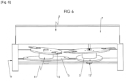
- the mechanical transmission system 15 can be a gear transmission system, as illustrated in figure 9 or chain or belt or other.
- the drive shaft of the hydraulic motor 14 engages, for example, via an elastic coupling with a shaft on which the discs 5 of an assembly 11 are mounted so as to rotate securely with the shaft.
- This rotating shaft carries, at its end opposite that engaged with the drive shaft, a pinion integral in rotation with the shaft.
- This pinion comes into engagement by meshing with a pinion carried by the disc-carrying shaft of the other set of discs.
- the rotation of one of the shafts involves, via the pinions, the rotation of the other shaft.
- the elastic coupling between the drive shaft of the hydraulic motor 14 and the disc carrier shaft of an assembly 11 is represented by the references 23, 24, 25.
- the pinion carried by this shaft is represented at 26.
- This pinion 26 meshes via an intermediate pinion 27 with a pinion mounted integral in rotation with the disc-carrying shaft of a second set 11 of discs of the cutting module.
- the front face 7 of the box 4 is, in the configuration of use of the box 4, in which the box is at least partially resting on the ground, surmounted by a deflector 16.
- This deflector 16 is in the form of an inclined plate extending in the extension of the upper edge of the front face 7 of the box 3 in the configuration of use of the box 3 resting on the ground as shown in figures 1 And 4 , For example.
- This plate constituting the deflector 16 is inclined forward from its low point of connection to the upper edge of the front face 7 of the box in the direction of its high point arranged in front of the front face of the box 3 with a downward slope from the high point in the direction of the low point.
- This deflector 16 tends to push the plants towards the interior of the box 3.
- the bottom face 10 and/or the side faces 9 of the box 4 are equipped with at least one ground support member 17, such as a ground support pad, of the box 4.
- the side faces 9 of the box 4 are provided, at their so-called lower edge in the configuration of use of ground support of the box 3, with a flat iron reinforcing this lower edge.
- This flat iron constitutes, in the manner of a ski, a skate which allows the box 4 to slide better on the ground during its movement and to be able to cross obstacles without damage.
- This flat iron is a wear part removably mounted on the lower edge of said lateral face 9.
- This flat iron can be adjustable in position on the lower edge of the lateral face 9.
- This flat iron extends to also protect one of the so-called lateral edges of the front face 7 of the box 4.
- the underside face 10 of the box 4 can also be provided with such reinforcing elements forming or not pads, depending on whether the underside face is arranged at the same level as the lower edge of the faces sides of the box or at a level higher than the lower edge of these side faces, as in the example shown.
- the cutting module 3 is, in the state coupled to the chassis 2, connected to the chassis 2 by a non-rigid connecting device 19 as illustrated for example in Figures 1 to 4 .
- This connecting device 19 comprises a plurality of flexible links 20, and each flexible link extends between a side face 9 or the top face 22 of the box 4, and the chassis 2.
- These flexible links 20 are here produced in the form of a chain. These flexible links are four in number with two links connecting the front part of the side faces of the box 4 to the chassis 2, and two links connecting the rear part of the side faces of the box 4 to the chassis 2.
- the links 20 arranged closest to the front face of the box are of shorter length than the links 20 arranged closest to the rear face 8 of the box 4.
- the front face of the box 4 is spaced from the ground and the box 4 is inclined with its underside sloping downward from the front to the rear of the box 4 as illustrated in FIG. figure 4 .
- This configuration which corresponds to a configuration of using ground support for box 4, facilitates the advancement of the cutting module.
- the soil working machine 1 is positioned in a cultivated area where crops are grown in rows, with the or each cutting module positioned along a row of crops, as illustrated in figure 1 .
- the tillage machine is driven to move along a line parallel to the crop row to move along said row.
- the discs of the cutting sets all rotate at the same speed.
- the stems of the plants are cut by the knives 12 at different heights to form plant fragments which fall to the ground.
Landscapes
- Life Sciences & Earth Sciences (AREA)
- Environmental Sciences (AREA)
- Soil Working Implements (AREA)
Claims (12)
- Pflanzenschneidemodul (3), das mit einem Rahmen (2) einer Bodenbearbeitungsmaschine (1) koppelbar ist, das Schneidmodul (3) umfassend einen Kasten (4), der auf dem Boden aufliegend positionierbar ist, mindestens eine drehende Schneidscheibe (5) mit sogenannter vertikaler Drehachse, die im Inneren des Kastens (4) untergebracht ist, und eine Vorrichtung (6) zum Drehantrieb der mindestens einen Scheibe (5), mit der der Kasten (4) ausgestattet ist, wobei der Kasten (4) in Gebrauchskonfiguration der Bodenstütze eine offene Vorderseite (7), eine gegenüberliegende Rückseite (8), Seitenflächen (9), eine Unterseite (10), die dem zu bearbeitenden Boden zugewandt ist, und eine gegenüberliegende Oberseite (22) aufweist, und wobei die sogenannte vertikale Drehachse der mindestens einen Scheibe (5) durch die Unterseite (10) und die Oberseite (22) des Kastens (4) verläuft, dadurch gekennzeichnet, dass die Anzahl der Schneidscheiben (5) mindestens gleich 4 ist, dass die drehfest montierten Schneidscheiben (5) mindestens zwei Scheibenanordnungen (11) bilden, die, von der Vorderseite (7) des Kastens aus gesehen in Gebrauchskonfiguration des Kastens (4), Seite an Seite im Inneren des Kastens (4) angeordnet sind, wobei jede Scheibenanordnung (11) mindestens zwei koaxiale, parallele, übereinander liegende Scheiben (5) umfasst, dass die Scheiben (5) einer der Anordnungen (11) und die Scheiben (5) der anderen oder einer weiteren Anordnung (11) gegenläufige Scheiben (5) sind, wobei jede Scheibe (5) einer Anordnung (11) koplanar mit einer Scheibe (5) der jeweils anderen Anordnung (11) ist, dass jede Scheibe (5) mindestens ein sogenanntes radiales Messer (12) trägt, das frei drehbar um eine Achse parallel zu der Drehachse der Scheibe (5) montiert ist, die es für eine Verschiebung des Messers (12) zwischen einer ausgestellten Position, in der es sich zumindest teilweise radial hervorstehend von der Scheibe (5) erstreckt, und einer eingezogenen Position trägt, dass die Messer (12) von einer Scheibe (5) zu einer anderen einer gleichen Anordnung (11) von Scheiben (5) und von einer Scheibe (5) einer Anordnung (11) von Scheiben (5) zu einer koplanaren Scheibe (5) einer anderen Anordnung (11) von Scheiben (5) winkelmäßig versetzt sind.
- Pflanzenschneidemodul (3) nach Anspruch 1, dadurch gekennzeichnet, dass die Messer (12), die von einer Scheibe (5) einer Anordnung (11) von Scheiben (5) zu einer koplanaren Scheibe (5) einer anderen Anordnung (11) von Scheiben (5) winkelmäßig um einen Winkel im Wesentlichen gleich wie 90° bis mehr oder weniger 30° versetzt sind.
- Pflanzenschneidemodul (3) nach einem der Ansprüche 1 oder 2, dadurch gekennzeichnet, dass jede Scheibe (5) eine kreisförmige, eiförmige oder dreieckige, vorzugsweise glatte Scheibe ist.
- Schneidmodul (3) von Pflanzen nach einem der Ansprüche 1 bis 3, dadurch gekennzeichnet, dass mindestens ein, vorzugsweise jedes Messer (12), aus einer rechteckigen Klinge gebildet ist, wovon mindestens zwei Kanten (13) scharf sind.
- Pflanzenschneidemodul (3) nach einem der Ansprüche 1 bis 4, dadurch gekennzeichnet, dass die Vorrichtung (6) zum Drehantrieb der Scheiben (5), mit denen der Kasten (4) ausgestattet ist, mindestens einen Motor (14), vorzugsweise hydraulisch, der sich von der Oberseite (22) des Kastens (4) hervorstehend erstreckt, und ein mechanisches System (15) zum Übertragen der Drehbewegung des Motors (14) auf die Scheiben (5) umfasst.
- Pflanzenschneidemodul (3) nach einem der Ansprüche 1 bis 5, dadurch gekennzeichnet, dass die Vorderseite (7) des Kastens (4) in Gebrauchskonfiguration des Kastens (4) von einem Deflektor (16) überbaut ist.
- Pflanzenschneidemodul (3) nach einem der Ansprüche 1 bis 6, dadurch gekennzeichnet, dass die Unterseite (10) und/oder die Seitenflächen (9) des Kastens (4) mit mindestens einem Bodenabstützelement (17), wie beispielsweise einer Bodenabstützkufe des Kastens (4), ausgestattet sind.
- Bodenbearbeitungsmaschine (1) für Reihenkulturen (21), umfassend mindestens einen Rahmen (2) und mindestens ein mit dem Rahmen koppelbares Pflanzenschneidmodul (3), dadurch gekennzeichnet, dass das oder mindestens eines, vorzugsweise jedes der Schneidmodule (3) einem der Ansprüche 1 bis 7 entspricht.
- Bodenbearbeitungsmaschine (1) nach Anspruch 8, dadurch gekennzeichnet, dass der Rahmen (2) mindestens einen Balken (18) umfasst, der dazu bestimmt ist, sich quer zu den Kulturreihen (21) zu erstrecken, dass die Anzahl der Schneidmodule (3) mindestens gleich zwei ist, und dass die Schneidmodule (3) axial versetzt entlang des Balkens (18) koppelbar sind.
- Bodenbearbeitungsmaschine (1) nach Anspruch 9, dadurch gekennzeichnet, dass der Balken (18) ein in der Länge verstellbarer Balken ist.
- Bodenbearbeitungsmaschine (1) nach einem der Ansprüche 8 bis 10, dadurch gekennzeichnet, dass jedes Schneidmodul (3) in dem mit dem Rahmen (2) gekoppelten Zustand durch eine nicht starre Verbindungsvorrichtung (19) mit dem Rahmen (2) verbunden ist, um es dem Kasten (4) des Schneidmoduls (3) zu ermöglichen, dem Bodenprofil zu folgen.
- Bodenbearbeitungsmaschine (1) nach Anspruch 11, dadurch gekennzeichnet, dass die Verbindungsvorrichtung (19) eine Vielzahl von flexiblen Verbindungen (20), wie beispielsweise Ketten, umfasst, dass sich jede flexible Verbindung (20) zwischen einer Seitenfläche (9) oder der Oberseite (22) des Kastens (4) und dem Rahmen (2) erstreckt und dass die Verbindungen (20), die am nächsten zu der Vorderseite (7) angeordnet sind, eine geringere Länge aufweisen als die Verbindungen (20), die am nächsten zu der Rückseite (8) des Kastens (4) angeordnet sind.
Applications Claiming Priority (1)
| Application Number | Priority Date | Filing Date | Title |
|---|---|---|---|
| FR2209245A FR3139429B1 (fr) | 2022-09-14 | 2022-09-14 | Module de coupe de végétaux dit inter-rang couplable à un châssis de machine de travail du sol et une machine de travail du sol comprenant au moins un module de coupe |
Publications (2)
| Publication Number | Publication Date |
|---|---|
| EP4338568A1 EP4338568A1 (de) | 2024-03-20 |
| EP4338568B1 true EP4338568B1 (de) | 2025-01-15 |
Family
ID=83899352
Family Applications (1)
| Application Number | Title | Priority Date | Filing Date |
|---|---|---|---|
| EP23195221.9A Active EP4338568B1 (de) | 2022-09-14 | 2023-09-04 | An einem bodenbearbeitungsmaschinenrahmen anschliessbares pflanzenschneidmodul und bodenbearbeitungsmaschine mit mindestens einem schneidmodul |
Country Status (2)
| Country | Link |
|---|---|
| EP (1) | EP4338568B1 (de) |
| FR (1) | FR3139429B1 (de) |
Family Cites Families (5)
| Publication number | Priority date | Publication date | Assignee | Title |
|---|---|---|---|---|
| NL6801100A (de) * | 1968-01-25 | 1969-07-29 | ||
| FR2594627B1 (fr) * | 1986-02-27 | 1988-06-17 | Kuhn Sa | Faucheuse rotative |
| JP4551333B2 (ja) * | 2006-01-12 | 2010-09-29 | 株式会社クボタ | 草刈機 |
| KR101242052B1 (ko) * | 2012-10-24 | 2013-03-11 | 천안논산고속도로주식회사 | 차량 장착용 예초장치 |
| CN216163455U (zh) * | 2021-10-14 | 2022-04-05 | 南通理工学院 | 一种用于除草机的粉碎装置 |
-
2022
- 2022-09-14 FR FR2209245A patent/FR3139429B1/fr active Active
-
2023
- 2023-09-04 EP EP23195221.9A patent/EP4338568B1/de active Active
Also Published As
| Publication number | Publication date |
|---|---|
| FR3139429A1 (fr) | 2024-03-15 |
| EP4338568A1 (de) | 2024-03-20 |
| FR3139429B1 (fr) | 2024-08-09 |
Similar Documents
| Publication | Publication Date | Title |
|---|---|---|
| EP1378159B1 (de) | Zerkleinerungsvorrichtung für Stoppel und Mähdrescher mit solcher Vorrichtung | |
| EP0312126B1 (de) | Schneidapparat zur Verwendung in der Landwirtschaft, dem Weinbau und der Baumgärtnerei | |
| EP1690446B1 (de) | Landwirtschaftliches Gerät für das Mähen von Produkten | |
| FR2458981A1 (fr) | Bati de machine agricole | |
| EP0239515A1 (de) | Rotationsmähwerk | |
| CA2327379C (fr) | Faucheuse | |
| EP0206965A1 (de) | Rotationsmäher | |
| EP0641157B1 (de) | Maschine zur abfallvernichtung auf bananenplantagen | |
| CH398163A (fr) | Faucheuse rotative | |
| FR2590441A2 (fr) | Faucheuse perfectionnee | |
| EP1250834A1 (de) | Heuwerbungsmaschine mit Schwadgruppierugsvorrichtung | |
| EP4338568B1 (de) | An einem bodenbearbeitungsmaschinenrahmen anschliessbares pflanzenschneidmodul und bodenbearbeitungsmaschine mit mindestens einem schneidmodul | |
| EP3935934B1 (de) | Landwirtschaftliches gerät mit einem mähbalken und einem abnehmbaren kollektor und landwirtschaftliche maschine mit einem solchen gerät | |
| EP1776856B1 (de) | Vegetations-Mähvorrichtung | |
| EP2923539A1 (de) | Sämaschine mit integrierter walze zum zerstören einer vegetationsdeckschicht | |
| FR2733115A1 (fr) | Dispositif debroussailleur-broyeur de vegetaux | |
| EP0756814B1 (de) | Buschmähergehäuse | |
| FR2685993A1 (fr) | Machine de coupe de vegetaux, notamment broyeur forestier. | |
| EP0053570A1 (de) | Frontal angeordneter Kreiselschwadrechen | |
| FR2644972A1 (fr) | Broyeur de tiges pour cueilleur a mais | |
| FR2908588A1 (fr) | Equipement d'ensileuse comportant un ramasseur repliable recevant une barre de coupe | |
| EP0093683B1 (de) | Landwirtschaftliche Maschinen zum Umsetzen von Viehfutter oder anderen auf dem Boden liegenden Pflanzen | |
| EP1659849A2 (de) | Vorrichtung zum mechanischen vergraben von pflanzenresten | |
| FR3126844A1 (fr) | Dispositif de contrôle de l’enherbement sous un rang de plantes | |
| FR3055510B1 (fr) | Vehicule autoporte de coupe et de broyage de vegetaux |
Legal Events
| Date | Code | Title | Description |
|---|---|---|---|
| PUAI | Public reference made under article 153(3) epc to a published international application that has entered the european phase |
Free format text: ORIGINAL CODE: 0009012 |
|
| STAA | Information on the status of an ep patent application or granted ep patent |
Free format text: STATUS: THE APPLICATION HAS BEEN PUBLISHED |
|
| AK | Designated contracting states |
Kind code of ref document: A1 Designated state(s): AL AT BE BG CH CY CZ DE DK EE ES FI FR GB GR HR HU IE IS IT LI LT LU LV MC ME MK MT NL NO PL PT RO RS SE SI SK SM TR |
|
| STAA | Information on the status of an ep patent application or granted ep patent |
Free format text: STATUS: REQUEST FOR EXAMINATION WAS MADE |
|
| 17P | Request for examination filed |
Effective date: 20240326 |
|
| RBV | Designated contracting states (corrected) |
Designated state(s): AL AT BE BG CH CY CZ DE DK EE ES FI FR GB GR HR HU IE IS IT LI LT LU LV MC ME MK MT NL NO PL PT RO RS SE SI SK SM TR |
|
| GRAP | Despatch of communication of intention to grant a patent |
Free format text: ORIGINAL CODE: EPIDOSNIGR1 |
|
| STAA | Information on the status of an ep patent application or granted ep patent |
Free format text: STATUS: GRANT OF PATENT IS INTENDED |
|
| RIC1 | Information provided on ipc code assigned before grant |
Ipc: A01D 34/835 20060101ALI20240802BHEP Ipc: A01D 34/81 20060101ALI20240802BHEP Ipc: A01D 34/73 20060101ALI20240802BHEP Ipc: A01D 34/66 20060101ALI20240802BHEP Ipc: A01D 34/64 20060101ALI20240802BHEP Ipc: A01D 34/63 20060101ALI20240802BHEP Ipc: A01D 34/62 20060101AFI20240802BHEP |
|
| INTG | Intention to grant announced |
Effective date: 20240821 |
|
| GRAS | Grant fee paid |
Free format text: ORIGINAL CODE: EPIDOSNIGR3 |
|
| GRAA | (expected) grant |
Free format text: ORIGINAL CODE: 0009210 |
|
| STAA | Information on the status of an ep patent application or granted ep patent |
Free format text: STATUS: THE PATENT HAS BEEN GRANTED |
|
| AK | Designated contracting states |
Kind code of ref document: B1 Designated state(s): AL AT BE BG CH CY CZ DE DK EE ES FI FR GB GR HR HU IE IS IT LI LT LU LV MC ME MK MT NL NO PL PT RO RS SE SI SK SM TR |
|
| REG | Reference to a national code |
Ref country code: CH Ref legal event code: EP Ref country code: GB Ref legal event code: FG4D Free format text: NOT ENGLISH |
|
| REG | Reference to a national code |
Ref country code: DE Ref legal event code: R096 Ref document number: 602023001681 Country of ref document: DE |
|
| REG | Reference to a national code |
Ref country code: IE Ref legal event code: FG4D Free format text: LANGUAGE OF EP DOCUMENT: FRENCH |
|
| REG | Reference to a national code |
Ref country code: NL Ref legal event code: MP Effective date: 20250115 |
|
| PG25 | Lapsed in a contracting state [announced via postgrant information from national office to epo] |
Ref country code: NL Free format text: LAPSE BECAUSE OF FAILURE TO SUBMIT A TRANSLATION OF THE DESCRIPTION OR TO PAY THE FEE WITHIN THE PRESCRIBED TIME-LIMIT Effective date: 20250115 |
|
| PG25 | Lapsed in a contracting state [announced via postgrant information from national office to epo] |
Ref country code: RS Free format text: LAPSE BECAUSE OF FAILURE TO SUBMIT A TRANSLATION OF THE DESCRIPTION OR TO PAY THE FEE WITHIN THE PRESCRIBED TIME-LIMIT Effective date: 20250415 |
|
| PG25 | Lapsed in a contracting state [announced via postgrant information from national office to epo] |
Ref country code: FI Free format text: LAPSE BECAUSE OF FAILURE TO SUBMIT A TRANSLATION OF THE DESCRIPTION OR TO PAY THE FEE WITHIN THE PRESCRIBED TIME-LIMIT Effective date: 20250115 |
|
| PG25 | Lapsed in a contracting state [announced via postgrant information from national office to epo] |
Ref country code: PL Free format text: LAPSE BECAUSE OF FAILURE TO SUBMIT A TRANSLATION OF THE DESCRIPTION OR TO PAY THE FEE WITHIN THE PRESCRIBED TIME-LIMIT Effective date: 20250115 |
|
| PG25 | Lapsed in a contracting state [announced via postgrant information from national office to epo] |
Ref country code: ES Free format text: LAPSE BECAUSE OF FAILURE TO SUBMIT A TRANSLATION OF THE DESCRIPTION OR TO PAY THE FEE WITHIN THE PRESCRIBED TIME-LIMIT Effective date: 20250115 |
|
| REG | Reference to a national code |
Ref country code: LT Ref legal event code: MG9D |
|
| PG25 | Lapsed in a contracting state [announced via postgrant information from national office to epo] |
Ref country code: IS Free format text: LAPSE BECAUSE OF FAILURE TO SUBMIT A TRANSLATION OF THE DESCRIPTION OR TO PAY THE FEE WITHIN THE PRESCRIBED TIME-LIMIT Effective date: 20250515 Ref country code: NO Free format text: LAPSE BECAUSE OF FAILURE TO SUBMIT A TRANSLATION OF THE DESCRIPTION OR TO PAY THE FEE WITHIN THE PRESCRIBED TIME-LIMIT Effective date: 20250415 |
|
| REG | Reference to a national code |
Ref country code: AT Ref legal event code: MK05 Ref document number: 1759183 Country of ref document: AT Kind code of ref document: T Effective date: 20250115 |
|
| PG25 | Lapsed in a contracting state [announced via postgrant information from national office to epo] |
Ref country code: HR Free format text: LAPSE BECAUSE OF FAILURE TO SUBMIT A TRANSLATION OF THE DESCRIPTION OR TO PAY THE FEE WITHIN THE PRESCRIBED TIME-LIMIT Effective date: 20250115 |
|
| PG25 | Lapsed in a contracting state [announced via postgrant information from national office to epo] |
Ref country code: PT Free format text: LAPSE BECAUSE OF FAILURE TO SUBMIT A TRANSLATION OF THE DESCRIPTION OR TO PAY THE FEE WITHIN THE PRESCRIBED TIME-LIMIT Effective date: 20250515 Ref country code: LV Free format text: LAPSE BECAUSE OF FAILURE TO SUBMIT A TRANSLATION OF THE DESCRIPTION OR TO PAY THE FEE WITHIN THE PRESCRIBED TIME-LIMIT Effective date: 20250115 |
|
| PG25 | Lapsed in a contracting state [announced via postgrant information from national office to epo] |
Ref country code: GR Free format text: LAPSE BECAUSE OF FAILURE TO SUBMIT A TRANSLATION OF THE DESCRIPTION OR TO PAY THE FEE WITHIN THE PRESCRIBED TIME-LIMIT Effective date: 20250416 Ref country code: BG Free format text: LAPSE BECAUSE OF FAILURE TO SUBMIT A TRANSLATION OF THE DESCRIPTION OR TO PAY THE FEE WITHIN THE PRESCRIBED TIME-LIMIT Effective date: 20250115 |
|
| PG25 | Lapsed in a contracting state [announced via postgrant information from national office to epo] |
Ref country code: AT Free format text: LAPSE BECAUSE OF FAILURE TO SUBMIT A TRANSLATION OF THE DESCRIPTION OR TO PAY THE FEE WITHIN THE PRESCRIBED TIME-LIMIT Effective date: 20250115 |
|
| PG25 | Lapsed in a contracting state [announced via postgrant information from national office to epo] |
Ref country code: SE Free format text: LAPSE BECAUSE OF FAILURE TO SUBMIT A TRANSLATION OF THE DESCRIPTION OR TO PAY THE FEE WITHIN THE PRESCRIBED TIME-LIMIT Effective date: 20250115 |
|
| PG25 | Lapsed in a contracting state [announced via postgrant information from national office to epo] |
Ref country code: SM Free format text: LAPSE BECAUSE OF FAILURE TO SUBMIT A TRANSLATION OF THE DESCRIPTION OR TO PAY THE FEE WITHIN THE PRESCRIBED TIME-LIMIT Effective date: 20250115 |
|
| PG25 | Lapsed in a contracting state [announced via postgrant information from national office to epo] |
Ref country code: DK Free format text: LAPSE BECAUSE OF FAILURE TO SUBMIT A TRANSLATION OF THE DESCRIPTION OR TO PAY THE FEE WITHIN THE PRESCRIBED TIME-LIMIT Effective date: 20250115 |
|
| PG25 | Lapsed in a contracting state [announced via postgrant information from national office to epo] |
Ref country code: IT Free format text: LAPSE BECAUSE OF FAILURE TO SUBMIT A TRANSLATION OF THE DESCRIPTION OR TO PAY THE FEE WITHIN THE PRESCRIBED TIME-LIMIT Effective date: 20250115 |
|
| REG | Reference to a national code |
Ref country code: DE Ref legal event code: R097 Ref document number: 602023001681 Country of ref document: DE |
|
| PG25 | Lapsed in a contracting state [announced via postgrant information from national office to epo] |
Ref country code: EE Free format text: LAPSE BECAUSE OF FAILURE TO SUBMIT A TRANSLATION OF THE DESCRIPTION OR TO PAY THE FEE WITHIN THE PRESCRIBED TIME-LIMIT Effective date: 20250115 Ref country code: CZ Free format text: LAPSE BECAUSE OF FAILURE TO SUBMIT A TRANSLATION OF THE DESCRIPTION OR TO PAY THE FEE WITHIN THE PRESCRIBED TIME-LIMIT Effective date: 20250115 |
|
| PG25 | Lapsed in a contracting state [announced via postgrant information from national office to epo] |
Ref country code: RO Free format text: LAPSE BECAUSE OF FAILURE TO SUBMIT A TRANSLATION OF THE DESCRIPTION OR TO PAY THE FEE WITHIN THE PRESCRIBED TIME-LIMIT Effective date: 20250115 |
|
| PG25 | Lapsed in a contracting state [announced via postgrant information from national office to epo] |
Ref country code: SK Free format text: LAPSE BECAUSE OF FAILURE TO SUBMIT A TRANSLATION OF THE DESCRIPTION OR TO PAY THE FEE WITHIN THE PRESCRIBED TIME-LIMIT Effective date: 20250115 |
|
| PLBE | No opposition filed within time limit |
Free format text: ORIGINAL CODE: 0009261 |
|
| STAA | Information on the status of an ep patent application or granted ep patent |
Free format text: STATUS: NO OPPOSITION FILED WITHIN TIME LIMIT |
|
| 26N | No opposition filed |
Effective date: 20251016 |
|
| PGFP | Annual fee paid to national office [announced via postgrant information from national office to epo] |
Ref country code: FR Payment date: 20251029 Year of fee payment: 3 |