EP4338141B1 - Automatic beverage vending machine - Google Patents
Automatic beverage vending machine Download PDFInfo
- Publication number
- EP4338141B1 EP4338141B1 EP22723807.8A EP22723807A EP4338141B1 EP 4338141 B1 EP4338141 B1 EP 4338141B1 EP 22723807 A EP22723807 A EP 22723807A EP 4338141 B1 EP4338141 B1 EP 4338141B1
- Authority
- EP
- European Patent Office
- Prior art keywords
- retention
- shaped
- dispensing assembly
- vending machine
- guide slot
- Prior art date
- Legal status (The legal status is an assumption and is not a legal conclusion. Google has not performed a legal analysis and makes no representation as to the accuracy of the status listed.)
- Active
Links
Images


Classifications
-
- G—PHYSICS
- G07—CHECKING-DEVICES
- G07F—COIN-FREED OR LIKE APPARATUS
- G07F13/00—Coin-freed apparatus for controlling dispensing or fluids, semiliquids or granular material from reservoirs
- G07F13/10—Coin-freed apparatus for controlling dispensing or fluids, semiliquids or granular material from reservoirs with associated dispensing of containers, e.g. cups or other articles
-
- A—HUMAN NECESSITIES
- A47—FURNITURE; DOMESTIC ARTICLES OR APPLIANCES; COFFEE MILLS; SPICE MILLS; SUCTION CLEANERS IN GENERAL
- A47J—KITCHEN EQUIPMENT; COFFEE MILLS; SPICE MILLS; APPARATUS FOR MAKING BEVERAGES
- A47J31/00—Apparatus for making beverages
- A47J31/44—Parts or details or accessories of beverage-making apparatus
- A47J31/4403—Constructional details
-
- G—PHYSICS
- G07—CHECKING-DEVICES
- G07F—COIN-FREED OR LIKE APPARATUS
- G07F13/00—Coin-freed apparatus for controlling dispensing or fluids, semiliquids or granular material from reservoirs
- G07F13/06—Coin-freed apparatus for controlling dispensing or fluids, semiliquids or granular material from reservoirs with selective dispensing of different fluids or materials or mixtures thereof
- G07F13/065—Coin-freed apparatus for controlling dispensing or fluids, semiliquids or granular material from reservoirs with selective dispensing of different fluids or materials or mixtures thereof for drink preparation
-
- G—PHYSICS
- G07—CHECKING-DEVICES
- G07F—COIN-FREED OR LIKE APPARATUS
- G07F9/00—Details other than those peculiar to special kinds or types of apparatus
- G07F9/10—Casings or parts thereof, e.g. with means for heating or cooling
Definitions
- the present invention relates to an automatic beverage vending machine.
- the automatic beverage vending machines comprise a cabinet or container, which has a front access opening closed by a door and houses a plurality of assemblies for producing beverages.
- Each cabinet also houses one or more different sub-assemblies that can be configured during the assembly of the vending machine according to the purchaser's requirements.
- the above sub-assemblies have support and attachment structures, which are in some cases connected to portions of the cabinet or to attachment frames also housed in the cabinet, or are connected to the door to move together with the door itself.
- connection to the door is generally preferred as the opening of the door makes the sub-assemblies directly and easily accessible.
- Document EP 2 645 343 A2 describes a snap-on quick coupling device having a sliding slot for a retention peg and snap-on locking teeth of the peg within the slot.
- the Applicant has been able to ascertain that, although they guarantee high stability, such connecting elements do not allow, however, to satisfy the ever-increasing need to be able to install sub-assemblies in a short time, but above all to be able to replace sub-assemblies in machines already in operation so as to reconfigure or retro-fit them, that is to say to adapt them easily and quickly to new dispensing requirements, with low efforts on the part of the operator and without the need to use loose fasteners and mechanical tools and mechanical implements for the insertion and extraction of these fasteners.
- Aim of the present invention is to realize an automatic beverage vending machine, which enables the problems set out above to be solved in a simple and economical manner so as to be able to meet the need indicated above.
- an automatic beverage vending machine is realized, as claimed in the appended claims.
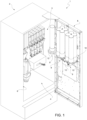
- reference number 1 denotes an automatic beverage vending machine as a whole.
- the automatic beverage vending machine 1 comprises a cabinet 2, in turn, comprising a box-shaped body 3 and a chamber 4 housing an assembly for preparing and dispensing one or more beverages, per se known and not described in detail and indicated by reference number 5.
- the chamber 4 communicates with the outside through an access opening 6 closed by a flap door 8, which forms part of the cabinet 2.
- the automatic beverage vending machine 1 also comprises three turret dispensing assemblies 9, commonly known as “feeding sub-assemblies”, for feeding paper or plastic cups of different sizes and, depending on the applications, also lids for closing the same cups and stir sticks. However, the dispensing assemblies of the closing lid and sticks may be missing.
- the dispensing assemblies 9 are carried by the door 8 and each is connected to the door 8 in a releasable or dismountable manner by a respective quick coupling and locking device 10 ( Figures 2 and 3 to 6 ) independent of the other quick coupling and locking devices 10.
- each dispensing assembly 9 comprises a dispensing base 11, per se known and not described, and its own attachment frame 12 partially or completely housing the relative dispensing base 11.
- Each quick coupling and locking device 10 comprises an upper pair 16 of retention pins 18 and a lower pair 19 of retention pins 18 vertically spaced from one another.
- the pins 18 protrude in a cantilever fashion from a surface 20 of the frame 12 facing the door 8.
- each retention pin 18 comprises a shaft 22, which is stably connected to the frame 12 and ends with an externally threaded segment, onto which a tightening nut 23 is screwed.
- a shaped collar 24, preferably, but not necessarily, made of an anti-friction material, is fitted on the shaft 22 and tightened against the surface 20 of the frame 12 by the relative nut 23.
- Each collar 24 has, in cross-section, a substantially H shape ( Figure 6 ) and comprises a central cylindrical portion 25 and two lateral circular flanges 26 and 27, of which the flange 27 has an outer diameter smaller than the outer diameter of the flange 26 and is positioned abutting against the relative nut 23 in order to define, with the nut 23 itself, an attachment head 28 of the relative retention pin 18.
- the flange 26 is positioned abutting against the surface 20 and delimits, with the cylindrical annular portion 25 and with the flange 27, a circumferential groove 29.
- each retention pin 18 is free of its relative collar 24 and the attachment head 28 is defined only by the nut 23.
- each quick coupling and locking device 10 further comprises a relative shaped attachment plate 30 of the pins 18 and fixed to the door 8.
- the shaped plates 30 constitute consecutive segments of a shaped crosspiece 31 that is common to all the dispensing assemblies 9 and stably connected to the door 8.
- the shaped attachment plates 30 are separated from each other and each stably connected to the door 8.
- each shaped plate 30 is C-shaped ( Figures 2 and 6 ) and comprises a vertical intermediate wall 32 and two horizontal side walls or wings 33 stably connected to the door 8 by means of nuts 34A.
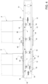
- Each intermediate wall 32 comprises, for each retention pin 18, a relative shaped retention and guide slot of the relative pin 18, indicated by 34 ( Figures 3 to 5 and 7 ).
- Each slot 34 comprises a vertical segment 35, a horizontal segment 36 and an inlet passage 37 arranged above the vertical segment 35 and communicating with the vertical segment 35 itself.
- part of the inlets 37 is obtained on the intermediate wall 32, the remaining part of the inlets 37 is obtained through the upper wing 33.
- the inlets 37 obtained through the wing 33 are inlets which are open upwards so as to allow the relative attachment head 28 to be inserted into the respective slot 34 by simply sliding in a vertical direction.
- all the inlets are obtained on the intermediate wall 32.
- each inlet 37 is configured to be crossed by the attachment head 28 of the relative pin 18, i.e. by the relative nut 23 and by the relative flange 27, but not by the relative flange 26.
- the segments 35 and 36 are shaped so as to have a width approximating by excess the outer diameter of the relative tubular portion 25 so as to allow the tubular portion 25 itself to slide freely within the segments 35 and 36.
- the frame 12 is brought into a position facing the crosspiece 31 by arranging the attachment heads 28 of the pins 18 at the relative inlets 37, after which the frame 12 is pushed against the crosspiece 31 and the attachment heads 28 of the pins advanced through the relative inlets 37 until the flanges 26 are brought against the wall 32.
- the frame 12 is lowered by advancing the tubular portions 25 of the pins 18, firstly, along the vertical segments 35 until they rest on the horizontal segments 36 and, then, it is translated horizontally by moving the tubular portions 25 themselves inside the horizontal segments 36 until they are brought in abutment against the bottom surfaces of the horizontal segments 36 themselves.
- the segments 35 and 36 extend along directions together forming an angle other than zero and 90°.
- each pin 40 is loaded with a spring so as to snap into its retention seat when the pins 18 reach the bottom surfaces of the segments 36.
- the quick coupling and locking devices 10 allow each of the dispensing assemblies 9 to be installed/removed and replaced independently of each other without using any loose fasteners and without the use of any tools and mechanical implements.
- each quick coupling and locking device 10 allows each dispensing assembly 9 to be arranged and locked in a unique and invariant position without the need for references and without attention on the part of the installer.
- the retention pins 18 could be configured in a manner different from that shown, but still in order to form part of a sliding engagement and could be in a number different from that shown.
- the automatic beverage vending machine 1 could comprise only one dispensing assembly 9.
- retention pins 18 could be carried by the shaped retention plates 30 and the slots 35 and 36 and the relative inlets 37 carried by the frame 12 of the dispensing assembly 9.
- pins 40 could be carried by the shaped retention plate 30 and the relative retention seat be carried by the dispensing assembly 9.
Landscapes
- Physics & Mathematics (AREA)
- General Physics & Mathematics (AREA)
- Engineering & Computer Science (AREA)
- Food Science & Technology (AREA)
- Control Of Vending Devices And Auxiliary Devices For Vending Devices (AREA)
- Beverage Vending Machines With Cups, And Gas Or Electricity Vending Machines (AREA)
- Devices For Dispensing Beverages (AREA)
- Vending Machines For Individual Products (AREA)
Priority Applications (4)
| Application Number | Priority Date | Filing Date | Title |
|---|---|---|---|
| HRP20241266TT HRP20241266T1 (hr) | 2021-05-10 | 2022-05-10 | Automatski stroj za prodaju napitaka |
| SM20240428T SMT202400428T1 (it) | 2021-05-10 | 2022-05-10 | Distributore automatico di bevande |
| SI202230054T SI4338141T1 (sl) | 2021-05-10 | 2022-05-10 | Avtomat za prodajo pijač |
| RS20241061A RS65991B1 (sr) | 2021-05-10 | 2022-05-10 | Automatska mašina za prodaju pića |
Applications Claiming Priority (2)
| Application Number | Priority Date | Filing Date | Title |
|---|---|---|---|
| IT102021000011945A IT202100011945A1 (it) | 2021-05-10 | 2021-05-10 | Distributore automatico di bevande |
| PCT/IB2022/054325 WO2022238887A1 (en) | 2021-05-10 | 2022-05-10 | Automatic beverage vending machine |
Publications (2)
| Publication Number | Publication Date |
|---|---|
| EP4338141A1 EP4338141A1 (en) | 2024-03-20 |
| EP4338141B1 true EP4338141B1 (en) | 2024-08-28 |
Family
ID=77519473
Family Applications (1)
| Application Number | Title | Priority Date | Filing Date |
|---|---|---|---|
| EP22723807.8A Active EP4338141B1 (en) | 2021-05-10 | 2022-05-10 | Automatic beverage vending machine |
Country Status (22)
| Country | Link |
|---|---|
| US (1) | US20240355167A1 (pl) |
| EP (1) | EP4338141B1 (pl) |
| JP (1) | JP2024520300A (pl) |
| KR (1) | KR20240033212A (pl) |
| CN (1) | CN117769728B (pl) |
| AU (1) | AU2022273946A1 (pl) |
| BR (1) | BR112023023637A2 (pl) |
| CA (1) | CA3218532A1 (pl) |
| DK (1) | DK4338141T3 (pl) |
| ES (1) | ES2991602T3 (pl) |
| FI (1) | FI4338141T3 (pl) |
| HR (1) | HRP20241266T1 (pl) |
| HU (1) | HUE068259T2 (pl) |
| IT (1) | IT202100011945A1 (pl) |
| LT (1) | LT4338141T (pl) |
| PL (1) | PL4338141T3 (pl) |
| PT (1) | PT4338141T (pl) |
| RS (1) | RS65991B1 (pl) |
| SI (1) | SI4338141T1 (pl) |
| SM (1) | SMT202400428T1 (pl) |
| TW (1) | TW202312109A (pl) |
| WO (1) | WO2022238887A1 (pl) |
Family Cites Families (13)
| Publication number | Priority date | Publication date | Assignee | Title |
|---|---|---|---|---|
| US2426707A (en) * | 1944-05-27 | 1947-09-02 | Blanche H Polsen | Dispensing apparatus |
| US2559063A (en) * | 1949-07-02 | 1951-07-03 | Rainbows Inc | Automatic drinking cup dispensing device |
| US3638448A (en) * | 1970-05-06 | 1972-02-01 | Umc Ind | Cleaning system for the ice maker of a vendor |
| DE3161234D1 (en) * | 1980-05-13 | 1983-11-24 | Ebo Ag | Mounting rack |
| JP3470662B2 (ja) * | 1999-11-26 | 2003-11-25 | 富士電機株式会社 | カップ供給装置 |
| US6209979B1 (en) * | 2000-02-22 | 2001-04-03 | General Devices Co., Ltd. | Telescoping slide with quick-mount system |
| JP3978115B2 (ja) * | 2002-11-12 | 2007-09-19 | サンデン株式会社 | 自動販売機の商品搬送装置及び自動販売機 |
| DE102009043941A1 (de) * | 2009-09-03 | 2011-03-10 | Wincor Nixdorf International Gmbh | Datenverarbeitungsvorrichtung |
| PL2369559T3 (pl) * | 2010-03-11 | 2017-05-31 | Rheavendors Services S.P.A. | Automat towarowy i sposób dozowania napojów |
| JP5559135B2 (ja) * | 2011-12-22 | 2014-07-23 | タキゲン製造株式会社 | 機器収納用ラック |
| KR101169059B1 (ko) * | 2012-03-30 | 2012-07-31 | 주식회사 빅솔론 | 휴대용 단말기를 이용한 포스 단말기 및 그 시스템 |
| WO2016010568A1 (en) * | 2014-07-18 | 2016-01-21 | Ferno-Washington, Inc. | Equipment mounting system |
| IT201800005953A1 (it) * | 2018-06-01 | 2019-12-01 | Distributore automatico di prodotti |
-
2021
- 2021-05-10 IT IT102021000011945A patent/IT202100011945A1/it unknown
-
2022
- 2022-05-09 TW TW111117365A patent/TW202312109A/zh unknown
- 2022-05-10 EP EP22723807.8A patent/EP4338141B1/en active Active
- 2022-05-10 LT LTEPPCT/IB2022/054325T patent/LT4338141T/lt unknown
- 2022-05-10 CN CN202280037418.2A patent/CN117769728B/zh active Active
- 2022-05-10 HR HRP20241266TT patent/HRP20241266T1/hr unknown
- 2022-05-10 ES ES22723807T patent/ES2991602T3/es active Active
- 2022-05-10 FI FIEP22723807.8T patent/FI4338141T3/fi active
- 2022-05-10 AU AU2022273946A patent/AU2022273946A1/en active Pending
- 2022-05-10 PL PL22723807.8T patent/PL4338141T3/pl unknown
- 2022-05-10 SI SI202230054T patent/SI4338141T1/sl unknown
- 2022-05-10 KR KR1020237042870A patent/KR20240033212A/ko active Pending
- 2022-05-10 CA CA3218532A patent/CA3218532A1/en active Pending
- 2022-05-10 PT PT227238078T patent/PT4338141T/pt unknown
- 2022-05-10 SM SM20240428T patent/SMT202400428T1/it unknown
- 2022-05-10 WO PCT/IB2022/054325 patent/WO2022238887A1/en not_active Ceased
- 2022-05-10 RS RS20241061A patent/RS65991B1/sr unknown
- 2022-05-10 DK DK22723807.8T patent/DK4338141T3/da active
- 2022-05-10 US US18/560,201 patent/US20240355167A1/en active Pending
- 2022-05-10 JP JP2023569901A patent/JP2024520300A/ja active Pending
- 2022-05-10 HU HUE22723807A patent/HUE068259T2/hu unknown
- 2022-05-10 BR BR112023023637A patent/BR112023023637A2/pt unknown
Also Published As
| Publication number | Publication date |
|---|---|
| HUE068259T2 (hu) | 2024-12-28 |
| IT202100011945A1 (it) | 2022-11-10 |
| HRP20241266T1 (hr) | 2024-12-06 |
| FI4338141T3 (fi) | 2024-09-24 |
| DK4338141T3 (da) | 2024-09-16 |
| JP2024520300A (ja) | 2024-05-24 |
| WO2022238887A1 (en) | 2022-11-17 |
| US20240355167A1 (en) | 2024-10-24 |
| CN117769728B (zh) | 2026-03-06 |
| PT4338141T (pt) | 2024-10-28 |
| AU2022273946A1 (en) | 2023-11-23 |
| ES2991602T3 (es) | 2024-12-04 |
| CA3218532A1 (en) | 2022-11-17 |
| SI4338141T1 (sl) | 2024-12-31 |
| RS65991B1 (sr) | 2024-10-31 |
| SMT202400428T1 (it) | 2024-11-15 |
| KR20240033212A (ko) | 2024-03-12 |
| TW202312109A (zh) | 2023-03-16 |
| PL4338141T3 (pl) | 2024-10-28 |
| BR112023023637A2 (pt) | 2024-01-23 |
| EP4338141A1 (en) | 2024-03-20 |
| LT4338141T (lt) | 2024-10-10 |
| CN117769728A (zh) | 2024-03-26 |
Similar Documents
| Publication | Publication Date | Title |
|---|---|---|
| US11771625B2 (en) | Storage container for a storage and dispensing station | |
| EP1681971B1 (en) | Universal collar | |
| EP4338141B1 (en) | Automatic beverage vending machine | |
| EP3610468B1 (de) | Vorratsbehälter für eine vorrats- und abgabestation | |
| US12344418B2 (en) | Storage container for a storage and dispensing station | |
| EP2820998A1 (en) | Basket arrangement for a dishwashing machine | |
| EP3576055B1 (en) | Vending machine | |
| DK3048590T3 (en) | DEVICE AND PROCEDURE FOR SUPPLYING COPPER IN A MACHINE FOR MANUFACTURING AND DELIVERY OF BEVERAGES | |
| US20040159623A1 (en) | Adjustable shelf system | |
| WO2000009301A1 (en) | Punch guide assembly | |
| US20180273368A1 (en) | Bottle Retaining Assembly With Quick Release For A Bottle Filler | |
| EP0799657B1 (en) | Mounting arrangement for loop distributor in a reforming chamber | |
| EP4491551A1 (en) | A magazine for at least one bundle of blanks | |
| EP3273824B1 (en) | Device for the movement and the support of support and containment elements of a furniture | |
| CN117730353A (zh) | 饮品自动售卖机 | |
| EP1530172A2 (en) | Distribution column for vending machines | |
| GB2107684A (en) | Apparatus for stoppering containers | |
| HK1226538A1 (en) | Device and method for feeding cups in a machine for preparing and dispensing beverages | |
| CH706770B1 (de) | Spendevorrichtung und Getränkeautomat mit einer Spendevorrichtung. | |
| HK1226538B (en) | Device and method for feeding cups in a machine for preparing and dispensing beverages | |
| MXPA97002419A (en) | Improved mounting provision for bond distributor in a modified chamber |
Legal Events
| Date | Code | Title | Description |
|---|---|---|---|
| REG | Reference to a national code |
Ref country code: HR Ref legal event code: TUEP Ref document number: P20241266T Country of ref document: HR |
|
| STAA | Information on the status of an ep patent application or granted ep patent |
Free format text: STATUS: UNKNOWN |
|
| STAA | Information on the status of an ep patent application or granted ep patent |
Free format text: STATUS: THE INTERNATIONAL PUBLICATION HAS BEEN MADE |
|
| PUAI | Public reference made under article 153(3) epc to a published international application that has entered the european phase |
Free format text: ORIGINAL CODE: 0009012 |
|
| STAA | Information on the status of an ep patent application or granted ep patent |
Free format text: STATUS: REQUEST FOR EXAMINATION WAS MADE |
|
| 17P | Request for examination filed |
Effective date: 20231127 |
|
| AK | Designated contracting states |
Kind code of ref document: A1 Designated state(s): AL AT BE BG CH CY CZ DE DK EE ES FI FR GB GR HR HU IE IS IT LI LT LU LV MC MK MT NL NO PL PT RO RS SE SI SK SM TR |
|
| GRAP | Despatch of communication of intention to grant a patent |
Free format text: ORIGINAL CODE: EPIDOSNIGR1 |
|
| STAA | Information on the status of an ep patent application or granted ep patent |
Free format text: STATUS: GRANT OF PATENT IS INTENDED |
|
| DAV | Request for validation of the european patent (deleted) | ||
| DAX | Request for extension of the european patent (deleted) | ||
| INTG | Intention to grant announced |
Effective date: 20240328 |
|
| GRAS | Grant fee paid |
Free format text: ORIGINAL CODE: EPIDOSNIGR3 |
|
| GRAA | (expected) grant |
Free format text: ORIGINAL CODE: 0009210 |
|
| STAA | Information on the status of an ep patent application or granted ep patent |
Free format text: STATUS: THE PATENT HAS BEEN GRANTED |
|
| P01 | Opt-out of the competence of the unified patent court (upc) registered |
Free format text: CASE NUMBER: APP_40159/2024 Effective date: 20240705 |
|
| AK | Designated contracting states |
Kind code of ref document: B1 Designated state(s): AL AT BE BG CH CY CZ DE DK EE ES FI FR GB GR HR HU IE IS IT LI LT LU LV MC MK MT NL NO PL PT RO RS SE SI SK SM TR |
|
| REG | Reference to a national code |
Ref country code: CH Ref legal event code: EP |
|
| REG | Reference to a national code |
Ref country code: DK Ref legal event code: T3 Effective date: 20240913 |
|
| REG | Reference to a national code |
Ref country code: DE Ref legal event code: R096 Ref document number: 602022005728 Country of ref document: DE |
|
| REG | Reference to a national code |
Ref country code: FI Ref legal event code: FGE |
|
| REG | Reference to a national code |
Ref country code: IE Ref legal event code: FG4D Ref country code: NL Ref legal event code: FP |
|
| REG | Reference to a national code |
Ref country code: SE Ref legal event code: TRGR |
|
| REG | Reference to a national code |
Ref country code: PT Ref legal event code: SC4A Ref document number: 4338141 Country of ref document: PT Date of ref document: 20241028 Kind code of ref document: T Free format text: AVAILABILITY OF NATIONAL TRANSLATION Effective date: 20241021 |
|
| REG | Reference to a national code |
Ref country code: EE Ref legal event code: FG4A Ref document number: E024627 Country of ref document: EE Effective date: 20240917 |
|
| REG | Reference to a national code |
Ref country code: GR Ref legal event code: EP Ref document number: 20240402247 Country of ref document: GR Effective date: 20241111 |
|
| REG | Reference to a national code |
Ref country code: SK Ref legal event code: T3 Ref document number: E 45155 Country of ref document: SK Ref country code: ES Ref legal event code: FG2A Ref document number: 2991602 Country of ref document: ES Kind code of ref document: T3 Effective date: 20241204 |
|
| REG | Reference to a national code |
Ref country code: HR Ref legal event code: T1PR Ref document number: P20241266 Country of ref document: HR |
|
| REG | Reference to a national code |
Ref country code: HU Ref legal event code: AG4A Ref document number: E068259 Country of ref document: HU |
|
| REG | Reference to a national code |
Ref country code: HR Ref legal event code: ODRP Ref document number: P20241266 Country of ref document: HR Payment date: 20250422 Year of fee payment: 4 |
|
| REG | Reference to a national code |
Ref country code: DE Ref legal event code: R097 Ref document number: 602022005728 Country of ref document: DE |
|
| PGFP | Annual fee paid to national office [announced via postgrant information from national office to epo] |
Ref country code: NL Payment date: 20250526 Year of fee payment: 4 |
|
| PGFP | Annual fee paid to national office [announced via postgrant information from national office to epo] |
Ref country code: SM Payment date: 20250523 Year of fee payment: 4 |
|
| PLBE | No opposition filed within time limit |
Free format text: ORIGINAL CODE: 0009261 |
|
| STAA | Information on the status of an ep patent application or granted ep patent |
Free format text: STATUS: NO OPPOSITION FILED WITHIN TIME LIMIT |
|
| PGFP | Annual fee paid to national office [announced via postgrant information from national office to epo] |
Ref country code: MC Payment date: 20250526 Year of fee payment: 4 |
|
| PGFP | Annual fee paid to national office [announced via postgrant information from national office to epo] |
Ref country code: FI Payment date: 20250526 Year of fee payment: 4 |
|
| PGFP | Annual fee paid to national office [announced via postgrant information from national office to epo] |
Ref country code: DE Payment date: 20250528 Year of fee payment: 4 Ref country code: PL Payment date: 20250424 Year of fee payment: 4 |
|
| PGFP | Annual fee paid to national office [announced via postgrant information from national office to epo] |
Ref country code: ES Payment date: 20250611 Year of fee payment: 4 Ref country code: DK Payment date: 20250526 Year of fee payment: 4 |
|
| PGFP | Annual fee paid to national office [announced via postgrant information from national office to epo] |
Ref country code: LT Payment date: 20250424 Year of fee payment: 4 |
|
| PGFP | Annual fee paid to national office [announced via postgrant information from national office to epo] |
Ref country code: RS Payment date: 20250424 Year of fee payment: 4 Ref country code: IS Payment date: 20250523 Year of fee payment: 4 Ref country code: HU Payment date: 20250429 Year of fee payment: 4 Ref country code: NO Payment date: 20250520 Year of fee payment: 4 |
|
| PGFP | Annual fee paid to national office [announced via postgrant information from national office to epo] |
Ref country code: AL Payment date: 20250529 Year of fee payment: 4 Ref country code: LU Payment date: 20250526 Year of fee payment: 4 Ref country code: BE Payment date: 20250526 Year of fee payment: 4 Ref country code: IT Payment date: 20250531 Year of fee payment: 4 |
|
| PGFP | Annual fee paid to national office [announced via postgrant information from national office to epo] |
Ref country code: HR Payment date: 20250422 Year of fee payment: 4 |
|
| PGFP | Annual fee paid to national office [announced via postgrant information from national office to epo] |
Ref country code: PT Payment date: 20250415 Year of fee payment: 4 Ref country code: LV Payment date: 20250526 Year of fee payment: 4 |
|
| PGFP | Annual fee paid to national office [announced via postgrant information from national office to epo] |
Ref country code: EE Payment date: 20250529 Year of fee payment: 4 Ref country code: FR Payment date: 20250526 Year of fee payment: 4 |
|
| PGFP | Annual fee paid to national office [announced via postgrant information from national office to epo] |
Ref country code: MT Payment date: 20250528 Year of fee payment: 4 Ref country code: BG Payment date: 20250527 Year of fee payment: 4 Ref country code: GR Payment date: 20250523 Year of fee payment: 4 |
|
| PGFP | Annual fee paid to national office [announced via postgrant information from national office to epo] |
Ref country code: CH Payment date: 20250601 Year of fee payment: 4 |
|
| PGFP | Annual fee paid to national office [announced via postgrant information from national office to epo] |
Ref country code: RO Payment date: 20250505 Year of fee payment: 4 Ref country code: AT Payment date: 20250721 Year of fee payment: 4 |
|
| PGFP | Annual fee paid to national office [announced via postgrant information from national office to epo] |
Ref country code: TR Payment date: 20250425 Year of fee payment: 4 Ref country code: SK Payment date: 20250422 Year of fee payment: 4 |
|
| PGFP | Annual fee paid to national office [announced via postgrant information from national office to epo] |
Ref country code: CZ Payment date: 20250424 Year of fee payment: 4 |
|
| PGFP | Annual fee paid to national office [announced via postgrant information from national office to epo] |
Ref country code: IE Payment date: 20250520 Year of fee payment: 4 |
|
| PGFP | Annual fee paid to national office [announced via postgrant information from national office to epo] |
Ref country code: SE Payment date: 20250526 Year of fee payment: 4 Ref country code: SI Payment date: 20250422 Year of fee payment: 4 |
|
| 26N | No opposition filed |
Effective date: 20250530 |
|
| PGFP | Annual fee paid to national office [announced via postgrant information from national office to epo] |
Ref country code: MK Payment date: 20250425 Year of fee payment: 4 |
|
| PGFP | Annual fee paid to national office [announced via postgrant information from national office to epo] |
Ref country code: CY Payment date: 20250423 Year of fee payment: 4 |
|
| REG | Reference to a national code |
Ref country code: AT Ref legal event code: UEP Ref document number: 1718839 Country of ref document: AT Kind code of ref document: T Effective date: 20240828 |