EP4337392B1 - Verfahren und vorrichtung zur analyse einer vorrichtung zum sprühen eines pharmazeutischen flüssigprodukts - Google Patents
Verfahren und vorrichtung zur analyse einer vorrichtung zum sprühen eines pharmazeutischen flüssigprodukts Download PDFInfo
- Publication number
- EP4337392B1 EP4337392B1 EP22711578.9A EP22711578A EP4337392B1 EP 4337392 B1 EP4337392 B1 EP 4337392B1 EP 22711578 A EP22711578 A EP 22711578A EP 4337392 B1 EP4337392 B1 EP 4337392B1
- Authority
- EP
- European Patent Office
- Prior art keywords
- flow
- receiving surface
- sensors
- compressed gas
- zone
- Prior art date
- Legal status (The legal status is an assumption and is not a legal conclusion. Google has not performed a legal analysis and makes no representation as to the accuracy of the status listed.)
- Active
Links
Images

Classifications
-
- B—PERFORMING OPERATIONS; TRANSPORTING
- B05—SPRAYING OR ATOMISING IN GENERAL; APPLYING FLUENT MATERIALS TO SURFACES, IN GENERAL
- B05B—SPRAYING APPARATUS; ATOMISING APPARATUS; NOZZLES
- B05B12/00—Arrangements for controlling delivery; Arrangements for controlling the spray area
- B05B12/08—Arrangements for controlling delivery; Arrangements for controlling the spray area responsive to condition of liquid or other fluent material to be discharged, of ambient medium or of target ; responsive to condition of spray devices or of supply means, e.g. pipes, pumps or their drive means
- B05B12/082—Arrangements for controlling delivery; Arrangements for controlling the spray area responsive to condition of liquid or other fluent material to be discharged, of ambient medium or of target ; responsive to condition of spray devices or of supply means, e.g. pipes, pumps or their drive means responsive to a condition of the discharged jet or spray, e.g. to jet shape, spray pattern or droplet size
-
- B—PERFORMING OPERATIONS; TRANSPORTING
- B05—SPRAYING OR ATOMISING IN GENERAL; APPLYING FLUENT MATERIALS TO SURFACES, IN GENERAL
- B05B—SPRAYING APPARATUS; ATOMISING APPARATUS; NOZZLES
- B05B12/00—Arrangements for controlling delivery; Arrangements for controlling the spray area
- B05B12/16—Arrangements for controlling delivery; Arrangements for controlling the spray area for controlling the spray area
- B05B12/18—Arrangements for controlling delivery; Arrangements for controlling the spray area for controlling the spray area using fluids, e.g. gas streams
-
- G—PHYSICS
- G01—MEASURING; TESTING
- G01F—MEASURING VOLUME, VOLUME FLOW, MASS FLOW OR LIQUID LEVEL; METERING BY VOLUME
- G01F1/00—Measuring the volume flow or mass flow of fluid or fluent solid material wherein the fluid passes through a meter in a continuous flow
- G01F1/76—Devices for measuring mass flow of a fluid or a fluent solid material
-
- A—HUMAN NECESSITIES
- A61—MEDICAL OR VETERINARY SCIENCE; HYGIENE
- A61M—DEVICES FOR INTRODUCING MEDIA INTO, OR ONTO, THE BODY; DEVICES FOR TRANSDUCING BODY MEDIA OR FOR TAKING MEDIA FROM THE BODY; DEVICES FOR PRODUCING OR ENDING SLEEP OR STUPOR
- A61M15/00—Inhalators
- A61M15/08—Inhaling devices inserted into the nose
-
- A—HUMAN NECESSITIES
- A61—MEDICAL OR VETERINARY SCIENCE; HYGIENE
- A61M—DEVICES FOR INTRODUCING MEDIA INTO, OR ONTO, THE BODY; DEVICES FOR TRANSDUCING BODY MEDIA OR FOR TAKING MEDIA FROM THE BODY; DEVICES FOR PRODUCING OR ENDING SLEEP OR STUPOR
- A61M2209/00—Ancillary equipment
- A61M2209/02—Equipment for testing the apparatus
-
- G—PHYSICS
- G01—MEASURING; TESTING
- G01F—MEASURING VOLUME, VOLUME FLOW, MASS FLOW OR LIQUID LEVEL; METERING BY VOLUME
- G01F1/00—Measuring the volume flow or mass flow of fluid or fluent solid material wherein the fluid passes through a meter in a continuous flow
- G01F1/68—Measuring the volume flow or mass flow of fluid or fluent solid material wherein the fluid passes through a meter in a continuous flow by using thermal effects
Definitions
- the present invention relates to a device and a method for analyzing spray generated by a pharmaceutical fluid product spraying device.
- Devices for spraying pharmaceutical fluid products are well known. They generally comprise a spray head provided with a spray orifice, assembled on a reservoir containing the fluid product to be dispensed. Particularly in nasal spray applications, the therapeutic efficacy of the sprayed fluid product may depend on the properties of the spray generated when the device is actuated. As is known, at the end of the assembly line, i.e. when the spray device is assembled, and just before being shipped to the manufacturer of the pharmaceutical fluid product for assembly on a corresponding reservoir, a certain number of samples of assembled devices are tested in the laboratory to verify whether the properties of the spray correspond to the predefined specifications.
- a disadvantage of this system is that it concerns assembled devices, and therefore destroys these devices which, after having been tested, can no longer be delivered to the customer.
- the document WO2018130791 proposes the visualization by strioscopy of a flow of hot or cold compressed air sent through a spray head. This method makes it possible to distinguish a spray from a jet, but does not allow the geometry and/or symmetry of the spray to be assessed, and therefore its conformity with given specifications. This method also has the disadvantage of requiring a strioscopic bench, which is relatively complex and expensive.
- the present invention aims to overcome the above-mentioned drawbacks.
- the present invention aims to provide a device and a method for analyzing a pharmaceutical fluid product spraying device which makes it possible to detect devices which do not comply with predetermined specifications.
- the present invention also aims to provide a device and an analysis method which is non-destructive to the devices tested.
- the present invention also aims to provide an analysis device and method which is largely automated.
- said predetermined specifications include a predetermined planar extent of the impact zone of said compressed gas flow on said receiving surface, such that spray heads for which said planar extent is similar to said predetermined planar extent are classified as compliant, and spray heads for which said planar extent is different from said predetermined planar extent are classified as non-compliant.
- said receiving surface comprises a plurality of openings, each being connected to a respective sensor.
- said sensors form a honeycomb network comprising at least two concentric sensor zones.
- each spraying device comprises a spraying head 1 provided with a spraying orifice 2.
- a spraying profile (not shown) may be provided upstream of said spraying orifice 2 to generate a spray at the outlet of the orifice.
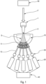
- the present invention provides for passing a flow of compressed gas F through a spray head 1, and directing this flow F, exiting the spray orifice 2 in the form of a conical spray S, towards a receiving surface 10 comprising a plurality of sensors 20.
- the flow of compressed gas F is a flow of compressed air, but it is understood that according to the invention, any suitable gas other than air could be used.
- FIG. 1 shows a test device according to an advantageous embodiment.
- the sensors 20 and/or the openings 11 form a honeycomb network comprising at least two concentric zones.
- the sensor network 20 may comprise a central zone with a single central sensor, and a first concentric zone, arranged radially outside said central zone, with six sensors.
- the sensor network 20 comprises a second concentric zone, arranged radially outside said first concentric zone, with twelve sensors. It is this configuration with nineteen sensors which is used for the analysis shown in the Figure 2 .
- the sensor network 20 may comprise a third concentric zone, arranged radially outside said second concentric zone, with eighteen sensors.
- This heat loss is compensated by supplying more energy to the heating element in order to maintain a constant ⁇ T between the two probes.
- the energy required to maintain this ⁇ T is proportional to the mass flow rate.
- analysis means 40 are advantageously provided to analyze the measurements of each sensor 30 and thus determine whether the impact zone of the compressed gas flow F from said spray head 1 on the receiving surface 10 complies or does not comply with predetermined specifications.
- the duration of the compressed gas pulse F is advantageously adjustable, in particular from 50 to 300 ms.
- the analysis means may comprise means for measuring the geometry of the impact zone of the compressed gas flow F on the receiving zone 10. For example, the barycenter of the impact zone is determined, and the maximum and minimum distances of this barycenter from the edge of the impact zone are measured. Comparison of these distances with predetermined values then makes it possible to evaluate the conformity of the device tested.
- the conformity assessment takes into account not only the surface area of the impact zone, but also its geometry, in particular its symmetry. This makes it possible to establish that a spray emerging from a compliant spray head will have an acceptable conical shape, both from the point of view of the angle of the spray and its symmetry.
- FIG. 2 illustrates a schematic representation obtained with the method and device of the invention, from which it is possible to evaluate in particular the planar extent and the geometry, in particular the symmetry, of the impact zone.
Landscapes
- Physics & Mathematics (AREA)
- Fluid Mechanics (AREA)
- General Physics & Mathematics (AREA)
- Measuring Volume Flow (AREA)
- Nozzles (AREA)
Claims (17)
- Verfahren zur Analyse einer Vorrichtung zum Sprühen eines fluiden pharmazeutischen Produkts, das die folgenden Schritte umfasst:- Bereitstellen eines Sprühkopfs (1) einer Vorrichtung zum Sprühen eines fluiden pharmazeutischen Produkts, wobei der Sprühkopf (1) eine einzige Sprühöffnung (2) aufweist,- Bereitstellen einer Empfangsfläche (10), die eine Vielzahl von Sensoren (20) aufweist,- Durchleiten eines Druckgasstroms (F) durch die Sprühöffnung (2) des Sprühkopfs (1),- Leiten des Druckgasstroms (F) auf die Empfangsfläche (10),- Visualisieren des Auftreffbereichs des Druckgasstroms (F) auf der Empfangsfläche (10) mit Hilfe der Sensoren (20), und- Analysieren der Visualisierung des Auftreffbereichs, um zu bestimmen, ob der Auftreffbereich vorbestimmten Spezifikationen entspricht oder nicht,dadurch gekennzeichnet, dass die Empfangsfläche (10) zumindest im Bereich des Auftreffbereichs des Druckgasstroms (F) kugelförmig ist,wobei der Analyseschritt die Bestimmung der Geometrie, insbesondere der Symmetrie, des Auftreffbereichs des Druckgasstroms (F) auf der Empfangsfläche (10) umfasst.
- Verfahren nach Anspruch 1, wobei der Druckgasstrom (F) ein Druckluftstrom ist.
- Verfahren nach einem der vorhergehenden Ansprüche, wobei die vorbestimmten Spezifikationen eine vorbestimmte planare Ausdehnung des Auftreffbereichs des Druckgasstroms (F) auf der Empfangsfläche (10) derart umfassen, dass die Sprühköpfe (1), für die die planare Ausdehnung der vorbestimmten planaren Ausdehnung ähnelt, als konform eingestuft werden und die Sprühköpfe (1), für die die planare Ausdehnung von der vorbestimmten planaren Ausdehnung abweicht, als nicht konform eingestuft werden.
- Verfahren nach einem der vorhergehenden Ansprüche, wobei die Empfangsfläche (10) von der Innenfläche eines Kugelabschnitts, insbesondere einer Halbkugel, gebildet wird.
- Verfahren nach einem der vorhergehenden Ansprüche, wobei die Empfangsfläche (10) eine Vielzahl von Öffnungen (11) aufweist, die jeweils mit einem entsprechenden Sensor (20) verbunden sind.
- Verfahren nach einem der vorhergehenden Ansprüche, wobei die Sensoren (20) ein Wabenmuster mit mindestens zwei konzentrischen Sensorbereichen bilden.
- Vorrichtung zur Analyse einer Vorrichtung zum Sprühen eines fluiden pharmazeutischen Produkts, umfassend:- einen Sprühkopf (1) einer Vorrichtung zum Sprühen eines fluiden pharmazeutischen Produkts, wobei der Sprühkopf (1) eine einzige Sprühöffnung (2) aufweist,- eine Empfangsfläche (10), die eine Vielzahl von Sensoren (20) aufweist,- Mittel zum Erzeugen (50) eines Druckgasstroms (F) zum Durchleiten eines Druckgasstroms (F) durch die Sprühöffnung (2) des Sprühkopfs (1) auf die Empfangsfläche (10),- Visualisierungsmittel zum Visualisieren des Auftreffbereichs des Druckgasstroms (F) auf der Empfangsfläche (10) mit Hilfe der Sensoren (20), und- Analysemittel (40) zum Analysieren der Visualisierung des Auftreffbereichs, um zu bestimmen, ob der Auftreffbereich vorbestimmten Spezifikationen entspricht oder nicht, dadurch gekennzeichnet, dass die Empfangsfläche (10) zumindest im Bereich des Auftreffbereichs des Druckgasstroms (F) kugelförmig ist,wobei die Sensoren (20) ein Wabenmuster mit mindestens zwei konzentrischen Sensorbereichen bilden.
- Vorrichtung nach Anspruch 7, wobei der Druckgasstrom (F) ein Druckluftstrom ist.
- Vorrichtung nach Anspruch 7 oder 8, wobei die Empfangsfläche (10) von der Innenfläche eines Kugelabschnitts, insbesondere einer Halbkugel, gebildet wird.
- Vorrichtung nach einem der Ansprüche 7 bis 9, wobei die Empfangsfläche (10) eine Vielzahl von Öffnungen (11) aufweist, die jeweils mit einem entsprechenden Sensor (20) verbunden sind.
- Vorrichtung nach einem der Ansprüche 7 bis 10, wobei vor jedem Sensor (20) ein Filter (30) angeordnet ist.
- Vorrichtung nach einem der Ansprüche 7 bis 11, wobei das Netz aus Sensoren (20) einen zentralen Bereich mit einem einzigen zentralen Sensor und einen ersten konzentrischen Bereich mit sechs Sensoren umfasst, der radial außerhalb des zentralen Bereichs angeordnet ist.
- Vorrichtung nach Anspruch 12, wobei das Netz aus Sensoren (20) einen zweiten konzentrischen Bereich mit zwölf Sensoren umfasst, der radial außerhalb des ersten konzentrischen Bereichs angeordnet ist.
- Vorrichtung nach Anspruch 13, wobei das Netz aus Sensoren (20) einen dritten konzentrischen Bereich mit achtzehn Sensoren umfasst, der radial außerhalb des zweiten konzentrischen Bereichs angeordnet ist.
- Vorrichtung nach einem der Ansprüche 7 bis 14, wobei die Sensoren (20) nahe beieinander liegen und so ein regelmäßiges und dichtes Netz aus Sensoren (20) auf der Empfangsfläche (10) bilden.
- Vorrichtung nach einem der Ansprüche 7 bis 15, wobei die Mittel (50) zum Erzeugen des Druckgasstroms (F) geeignet sind, Impulse mit einstellbarer Dauer, insbesondere von 50 bis 300 ms, zu erzeugen.
- Vorrichtung nach einem der Ansprüche 7 bis 16, wobei die Sensoren (20) Massendurchflusssensoren sind.
Applications Claiming Priority (2)
| Application Number | Priority Date | Filing Date | Title |
|---|---|---|---|
| FR2104936A FR3122733B1 (fr) | 2021-05-10 | 2021-05-10 | Procédé et dispositif d'analyse d'un dispositif de pulvérisation de produit fluide pharmaceutique |
| PCT/FR2022/050354 WO2022238628A1 (fr) | 2021-05-10 | 2022-02-28 | Procédé et dispositif d'analyse d'un dispositif de pulvérisation de produit fluide pharmaceutique |
Publications (2)
| Publication Number | Publication Date |
|---|---|
| EP4337392A1 EP4337392A1 (de) | 2024-03-20 |
| EP4337392B1 true EP4337392B1 (de) | 2025-05-14 |
Family
ID=76523148
Family Applications (1)
| Application Number | Title | Priority Date | Filing Date |
|---|---|---|---|
| EP22711578.9A Active EP4337392B1 (de) | 2021-05-10 | 2022-02-28 | Verfahren und vorrichtung zur analyse einer vorrichtung zum sprühen eines pharmazeutischen flüssigprodukts |
Country Status (5)
| Country | Link |
|---|---|
| US (1) | US20240255330A1 (de) |
| EP (1) | EP4337392B1 (de) |
| CN (1) | CN117615858A (de) |
| FR (1) | FR3122733B1 (de) |
| WO (1) | WO2022238628A1 (de) |
Family Cites Families (9)
| Publication number | Priority date | Publication date | Assignee | Title |
|---|---|---|---|---|
| JPS5427347B2 (de) | 1972-08-23 | 1979-09-10 | ||
| JPS54127347A (en) * | 1978-03-27 | 1979-10-03 | Yoshino Kogyosho Co Ltd | Method of and device for inspecting atomizing performance of spray nozzle head |
| JP2700570B2 (ja) * | 1988-11-07 | 1998-01-21 | 株式会社ゼクセル | 噴霧特性の検査方法 |
| US5753806A (en) * | 1996-10-30 | 1998-05-19 | Southwest Research Institute | Apparatus and method for determining the distribution and flow rate characteristics of an injection nozzle |
| KR200152780Y1 (ko) * | 1997-01-18 | 1999-07-15 | 박상록 | 디젤엔진용 분사노즐의 각도 및 할도 측정장치 |
| KR100507175B1 (ko) * | 2002-11-21 | 2005-08-11 | 현대자동차주식회사 | 디젤엔진 인젝터의 분공간 상대 불균율 측정장치 |
| ES2661097T3 (es) * | 2015-01-26 | 2018-03-27 | Inman S.R.L. | Dispositivo y procedimiento para controlar un patrón de pulverización |
| FR3061967B1 (fr) | 2017-01-16 | 2021-04-09 | Aptar France Sas | Procede d'analyse d'un spray genere par un dispositif de distribution de produit fluide |
| DE102017218677B4 (de) * | 2017-10-19 | 2020-04-16 | Ford Global Technologies, Llc | Verfahren zur Ermittlung einer Verteilung eines Impulses eines Einspritzstrahls einer Einspritzvorrichtung |
-
2021
- 2021-05-10 FR FR2104936A patent/FR3122733B1/fr active Active
-
2022
- 2022-02-28 WO PCT/FR2022/050354 patent/WO2022238628A1/fr not_active Ceased
- 2022-02-28 US US18/290,054 patent/US20240255330A1/en active Pending
- 2022-02-28 EP EP22711578.9A patent/EP4337392B1/de active Active
- 2022-02-28 CN CN202280034239.3A patent/CN117615858A/zh active Pending
Also Published As
| Publication number | Publication date |
|---|---|
| US20240255330A1 (en) | 2024-08-01 |
| FR3122733B1 (fr) | 2024-03-08 |
| EP4337392A1 (de) | 2024-03-20 |
| FR3122733A1 (fr) | 2022-11-11 |
| CN117615858A (zh) | 2024-02-27 |
| WO2022238628A1 (fr) | 2022-11-17 |
Similar Documents
| Publication | Publication Date | Title |
|---|---|---|
| EP2936145B1 (de) | Vorrichtung und verfahren zur unterscheidung von gasen in einer probe | |
| US6996478B2 (en) | Multiple sensing system and device | |
| EP3568688B1 (de) | Verfahren zur analyse eines durch eine vorrichtung zur abgabe eines flüssigen pharmazeutischen produkts erzeugten sprays | |
| WO2011148094A1 (fr) | Dispositif d'acquisition/distribution multipoints de fluide, en particulier sonde de prise de pression dans une entrée d'air de turbomachine | |
| Agrawal et al. | Rainbow schlieren deflectometry for scalar measurements in fluid flows | |
| US20140268143A1 (en) | Method and device for determining characteristic properties of a transparent particle | |
| CN105899919A (zh) | 使用开普勒行星运动定律的涂层表面纹理分析 | |
| EP4337392B1 (de) | Verfahren und vorrichtung zur analyse einer vorrichtung zum sprühen eines pharmazeutischen flüssigprodukts | |
| Jordan et al. | Spatially-resolved spray measurements and their implications | |
| EP4175761B1 (de) | Verfahren sowie vorrichtung zur kontrolle einer sprühvorrichtung eines pharmazeutischen flüssigen produkts | |
| Ullom et al. | A simple optical patternator for evaluating spray symmetry | |
| FR3001292A1 (fr) | Procede et dispositif de mesure de la concentration en agent d'extinction dans une zone feu | |
| EP4457035B1 (de) | Verfahren und vorrichtung zur analyse einer vorrichtung zum sprühen eines pharmazeutischen flüssigprodukts | |
| EP4457034B1 (de) | Verfahren und vorrichtung zur analyse einer vorrichtung zum sprühen eines pharmazeutischen flüssigprodukts | |
| BE1026619B1 (fr) | Systeme de mesure pour turbomachine | |
| CA2894855A1 (en) | Method and device for the near-surface, non-destructive inspection by means of ultrasound of a rotationally symmetric workpiece having a diameter that changes from section to section | |
| Sangeorzan et al. | Time-resolved drop size measurements in an intermittent high-pressure fuel spray | |
| Cejpek et al. | Combined drop sizing using phase Doppler anemometry and high-speed imaging | |
| CN113504298A (zh) | 超声透射传感器与多电极电导传感器持气率组合测量方法 | |
| Bade et al. | Generating Planar Statistics from Point Measurements in a Spray | |
| Ginzel | Civa modelling for internal ultrasonic tube testing | |
| Sankar et al. | Characterization of Liquid-Liquid Mixing in Sprays Using Rainbow Refractometry | |
| WO2001013104A1 (en) | Testing and monitoring systems | |
| Brenci et al. | Coherent fiber optic backscattering system for photon correlation spectroscopy | |
| Grzesik et al. | Measurement methods for determining the parameters of injectors in internal combustion engines |
Legal Events
| Date | Code | Title | Description |
|---|---|---|---|
| STAA | Information on the status of an ep patent application or granted ep patent |
Free format text: STATUS: UNKNOWN |
|
| STAA | Information on the status of an ep patent application or granted ep patent |
Free format text: STATUS: THE INTERNATIONAL PUBLICATION HAS BEEN MADE |
|
| PUAI | Public reference made under article 153(3) epc to a published international application that has entered the european phase |
Free format text: ORIGINAL CODE: 0009012 |
|
| STAA | Information on the status of an ep patent application or granted ep patent |
Free format text: STATUS: REQUEST FOR EXAMINATION WAS MADE |
|
| 17P | Request for examination filed |
Effective date: 20231204 |
|
| AK | Designated contracting states |
Kind code of ref document: A1 Designated state(s): AL AT BE BG CH CY CZ DE DK EE ES FI FR GB GR HR HU IE IS IT LI LT LU LV MC MK MT NL NO PL PT RO RS SE SI SK SM TR |
|
| P01 | Opt-out of the competence of the unified patent court (upc) registered |
Free format text: CASE NUMBER: APP_36867/2024 Effective date: 20240620 |
|
| DAV | Request for validation of the european patent (deleted) | ||
| DAX | Request for extension of the european patent (deleted) | ||
| GRAP | Despatch of communication of intention to grant a patent |
Free format text: ORIGINAL CODE: EPIDOSNIGR1 |
|
| STAA | Information on the status of an ep patent application or granted ep patent |
Free format text: STATUS: GRANT OF PATENT IS INTENDED |
|
| RIC1 | Information provided on ipc code assigned before grant |
Ipc: G01F 1/68 20060101ALN20241121BHEP Ipc: A61M 15/08 20060101ALN20241121BHEP Ipc: B05B 12/08 20060101AFI20241121BHEP |
|
| INTG | Intention to grant announced |
Effective date: 20241217 |
|
| GRAS | Grant fee paid |
Free format text: ORIGINAL CODE: EPIDOSNIGR3 |
|
| GRAA | (expected) grant |
Free format text: ORIGINAL CODE: 0009210 |
|
| STAA | Information on the status of an ep patent application or granted ep patent |
Free format text: STATUS: THE PATENT HAS BEEN GRANTED |
|
| AK | Designated contracting states |
Kind code of ref document: B1 Designated state(s): AL AT BE BG CH CY CZ DE DK EE ES FI FR GB GR HR HU IE IS IT LI LT LU LV MC MK MT NL NO PL PT RO RS SE SI SK SM TR |
|
| REG | Reference to a national code |
Ref country code: GB Ref legal event code: FG4D Free format text: NOT ENGLISH |
|
| REG | Reference to a national code |
Ref country code: CH Ref legal event code: EP |
|
| REG | Reference to a national code |
Ref country code: DE Ref legal event code: R096 Ref document number: 602022014652 Country of ref document: DE |
|
| REG | Reference to a national code |
Ref country code: IE Ref legal event code: FG4D Free format text: LANGUAGE OF EP DOCUMENT: FRENCH |
|
| REG | Reference to a national code |
Ref country code: NL Ref legal event code: MP Effective date: 20250514 |
|
| PG25 | Lapsed in a contracting state [announced via postgrant information from national office to epo] |
Ref country code: PT Free format text: LAPSE BECAUSE OF FAILURE TO SUBMIT A TRANSLATION OF THE DESCRIPTION OR TO PAY THE FEE WITHIN THE PRESCRIBED TIME-LIMIT Effective date: 20250915 Ref country code: ES Free format text: LAPSE BECAUSE OF FAILURE TO SUBMIT A TRANSLATION OF THE DESCRIPTION OR TO PAY THE FEE WITHIN THE PRESCRIBED TIME-LIMIT Effective date: 20250514 Ref country code: FI Free format text: LAPSE BECAUSE OF FAILURE TO SUBMIT A TRANSLATION OF THE DESCRIPTION OR TO PAY THE FEE WITHIN THE PRESCRIBED TIME-LIMIT Effective date: 20250514 |
|
| REG | Reference to a national code |
Ref country code: LT Ref legal event code: MG9D |
|
| PG25 | Lapsed in a contracting state [announced via postgrant information from national office to epo] |
Ref country code: GR Free format text: LAPSE BECAUSE OF FAILURE TO SUBMIT A TRANSLATION OF THE DESCRIPTION OR TO PAY THE FEE WITHIN THE PRESCRIBED TIME-LIMIT Effective date: 20250815 Ref country code: NO Free format text: LAPSE BECAUSE OF FAILURE TO SUBMIT A TRANSLATION OF THE DESCRIPTION OR TO PAY THE FEE WITHIN THE PRESCRIBED TIME-LIMIT Effective date: 20250814 |
|
| PG25 | Lapsed in a contracting state [announced via postgrant information from national office to epo] |
Ref country code: NL Free format text: LAPSE BECAUSE OF FAILURE TO SUBMIT A TRANSLATION OF THE DESCRIPTION OR TO PAY THE FEE WITHIN THE PRESCRIBED TIME-LIMIT Effective date: 20250514 Ref country code: PL Free format text: LAPSE BECAUSE OF FAILURE TO SUBMIT A TRANSLATION OF THE DESCRIPTION OR TO PAY THE FEE WITHIN THE PRESCRIBED TIME-LIMIT Effective date: 20250514 |
|
| REG | Reference to a national code |
Ref country code: AT Ref legal event code: MK05 Ref document number: 1794384 Country of ref document: AT Kind code of ref document: T Effective date: 20250514 |
|
| PG25 | Lapsed in a contracting state [announced via postgrant information from national office to epo] |
Ref country code: BG Free format text: LAPSE BECAUSE OF FAILURE TO SUBMIT A TRANSLATION OF THE DESCRIPTION OR TO PAY THE FEE WITHIN THE PRESCRIBED TIME-LIMIT Effective date: 20250514 |
|
| PG25 | Lapsed in a contracting state [announced via postgrant information from national office to epo] |
Ref country code: HR Free format text: LAPSE BECAUSE OF FAILURE TO SUBMIT A TRANSLATION OF THE DESCRIPTION OR TO PAY THE FEE WITHIN THE PRESCRIBED TIME-LIMIT Effective date: 20250514 |
|
| PG25 | Lapsed in a contracting state [announced via postgrant information from national office to epo] |
Ref country code: AT Free format text: LAPSE BECAUSE OF FAILURE TO SUBMIT A TRANSLATION OF THE DESCRIPTION OR TO PAY THE FEE WITHIN THE PRESCRIBED TIME-LIMIT Effective date: 20250514 |
|
| PG25 | Lapsed in a contracting state [announced via postgrant information from national office to epo] |
Ref country code: RS Free format text: LAPSE BECAUSE OF FAILURE TO SUBMIT A TRANSLATION OF THE DESCRIPTION OR TO PAY THE FEE WITHIN THE PRESCRIBED TIME-LIMIT Effective date: 20250814 |
|
| PG25 | Lapsed in a contracting state [announced via postgrant information from national office to epo] |
Ref country code: IS Free format text: LAPSE BECAUSE OF FAILURE TO SUBMIT A TRANSLATION OF THE DESCRIPTION OR TO PAY THE FEE WITHIN THE PRESCRIBED TIME-LIMIT Effective date: 20250914 |
|
| PG25 | Lapsed in a contracting state [announced via postgrant information from national office to epo] |
Ref country code: LV Free format text: LAPSE BECAUSE OF FAILURE TO SUBMIT A TRANSLATION OF THE DESCRIPTION OR TO PAY THE FEE WITHIN THE PRESCRIBED TIME-LIMIT Effective date: 20250514 |
|
| PG25 | Lapsed in a contracting state [announced via postgrant information from national office to epo] |
Ref country code: DK Free format text: LAPSE BECAUSE OF FAILURE TO SUBMIT A TRANSLATION OF THE DESCRIPTION OR TO PAY THE FEE WITHIN THE PRESCRIBED TIME-LIMIT Effective date: 20250514 Ref country code: SM Free format text: LAPSE BECAUSE OF FAILURE TO SUBMIT A TRANSLATION OF THE DESCRIPTION OR TO PAY THE FEE WITHIN THE PRESCRIBED TIME-LIMIT Effective date: 20250514 |
|
| PG25 | Lapsed in a contracting state [announced via postgrant information from national office to epo] |
Ref country code: CZ Free format text: LAPSE BECAUSE OF FAILURE TO SUBMIT A TRANSLATION OF THE DESCRIPTION OR TO PAY THE FEE WITHIN THE PRESCRIBED TIME-LIMIT Effective date: 20250514 |
|
| PG25 | Lapsed in a contracting state [announced via postgrant information from national office to epo] |
Ref country code: EE Free format text: LAPSE BECAUSE OF FAILURE TO SUBMIT A TRANSLATION OF THE DESCRIPTION OR TO PAY THE FEE WITHIN THE PRESCRIBED TIME-LIMIT Effective date: 20250514 |
|
| PG25 | Lapsed in a contracting state [announced via postgrant information from national office to epo] |
Ref country code: SK Free format text: LAPSE BECAUSE OF FAILURE TO SUBMIT A TRANSLATION OF THE DESCRIPTION OR TO PAY THE FEE WITHIN THE PRESCRIBED TIME-LIMIT Effective date: 20250514 |
|
| REG | Reference to a national code |
Ref country code: DE Ref legal event code: R097 Ref document number: 602022014652 Country of ref document: DE |
|
| PLBE | No opposition filed within time limit |
Free format text: ORIGINAL CODE: 0009261 |
|
| STAA | Information on the status of an ep patent application or granted ep patent |
Free format text: STATUS: NO OPPOSITION FILED WITHIN TIME LIMIT |
|
| REG | Reference to a national code |
Ref country code: CH Ref legal event code: L10 Free format text: ST27 STATUS EVENT CODE: U-0-0-L10-L00 (AS PROVIDED BY THE NATIONAL OFFICE) Effective date: 20260325 |
|
| PGFP | Annual fee paid to national office [announced via postgrant information from national office to epo] |
Ref country code: GB Payment date: 20260219 Year of fee payment: 5 |
|
| PGFP | Annual fee paid to national office [announced via postgrant information from national office to epo] |
Ref country code: DE Payment date: 20260206 Year of fee payment: 5 |
|
| PGFP | Annual fee paid to national office [announced via postgrant information from national office to epo] |
Ref country code: IT Payment date: 20260209 Year of fee payment: 5 |
|
| PGFP | Annual fee paid to national office [announced via postgrant information from national office to epo] |
Ref country code: FR Payment date: 20260227 Year of fee payment: 5 |
|
| 26N | No opposition filed |
Effective date: 20260217 |